WO2021199867A1 - 送電装置、受電装置、制御方法、およびプログラム - Google Patents
送電装置、受電装置、制御方法、およびプログラム Download PDFInfo
- Publication number
- WO2021199867A1 WO2021199867A1 PCT/JP2021/008184 JP2021008184W WO2021199867A1 WO 2021199867 A1 WO2021199867 A1 WO 2021199867A1 JP 2021008184 W JP2021008184 W JP 2021008184W WO 2021199867 A1 WO2021199867 A1 WO 2021199867A1
- Authority
- WO
- WIPO (PCT)
- Prior art keywords
- power
- power receiving
- value
- power transmission
- receiving device
- Prior art date
- Legal status (The legal status is an assumption and is not a legal conclusion. Google has not performed a legal analysis and makes no representation as to the accuracy of the status listed.)
- Ceased
Links
Images


Classifications
-
- G—PHYSICS
- G01—MEASURING; TESTING
- G01R—MEASURING ELECTRIC VARIABLES; MEASURING MAGNETIC VARIABLES
- G01R31/00—Arrangements for testing electric properties; Arrangements for locating electric faults; Arrangements for electrical testing characterised by what is being tested not provided for elsewhere
- G01R31/28—Testing of electronic circuits, e.g. by signal tracer
- G01R31/282—Testing of electronic circuits specially adapted for particular applications not provided for elsewhere
- G01R31/2822—Testing of electronic circuits specially adapted for particular applications not provided for elsewhere of microwave or radiofrequency circuits
- G01R31/2824—Testing of electronic circuits specially adapted for particular applications not provided for elsewhere of microwave or radiofrequency circuits testing of oscillators or resonators
-
- H—ELECTRICITY
- H02—GENERATION; CONVERSION OR DISTRIBUTION OF ELECTRIC POWER
- H02J—CIRCUIT ARRANGEMENTS OR SYSTEMS FOR SUPPLYING OR DISTRIBUTING ELECTRIC POWER; SYSTEMS FOR STORING ELECTRIC ENERGY
- H02J50/00—Circuit arrangements or systems for wireless supply or distribution of electric power
- H02J50/60—Circuit arrangements or systems for wireless supply or distribution of electric power responsive to the presence of foreign objects, e.g. detection of living beings
-
- G—PHYSICS
- G01—MEASURING; TESTING
- G01R—MEASURING ELECTRIC VARIABLES; MEASURING MAGNETIC VARIABLES
- G01R19/00—Arrangements for measuring currents or voltages or for indicating presence or sign thereof
- G01R19/12—Measuring rate of change
-
- H—ELECTRICITY
- H02—GENERATION; CONVERSION OR DISTRIBUTION OF ELECTRIC POWER
- H02J—CIRCUIT ARRANGEMENTS OR SYSTEMS FOR SUPPLYING OR DISTRIBUTING ELECTRIC POWER; SYSTEMS FOR STORING ELECTRIC ENERGY
- H02J50/00—Circuit arrangements or systems for wireless supply or distribution of electric power
- H02J50/10—Circuit arrangements or systems for wireless supply or distribution of electric power using inductive coupling
- H02J50/12—Circuit arrangements or systems for wireless supply or distribution of electric power using inductive coupling of the resonant type
-
- H—ELECTRICITY
- H02—GENERATION; CONVERSION OR DISTRIBUTION OF ELECTRIC POWER
- H02J—CIRCUIT ARRANGEMENTS OR SYSTEMS FOR SUPPLYING OR DISTRIBUTING ELECTRIC POWER; SYSTEMS FOR STORING ELECTRIC ENERGY
- H02J50/00—Circuit arrangements or systems for wireless supply or distribution of electric power
- H02J50/80—Circuit arrangements or systems for wireless supply or distribution of electric power involving the exchange of data, concerning supply or distribution of electric power, between transmitting devices and receiving devices
-
- H—ELECTRICITY
- H02—GENERATION; CONVERSION OR DISTRIBUTION OF ELECTRIC POWER
- H02J—CIRCUIT ARRANGEMENTS OR SYSTEMS FOR SUPPLYING OR DISTRIBUTING ELECTRIC POWER; SYSTEMS FOR STORING ELECTRIC ENERGY
- H02J7/00—Circuit arrangements for charging or depolarising batteries or for supplying loads from batteries
- H02J7/00032—Circuit arrangements for charging or depolarising batteries or for supplying loads from batteries characterised by data exchange
- H02J7/00034—Charger exchanging data with an electronic device, i.e. telephone, whose internal battery is under charge
Definitions
- the present invention relates to a power transmission device, a power receiving device, a control method, and a program, and more particularly to a foreign matter detection technique in wireless power transmission.
- Patent Document 1 describes a method of detecting a foreign substance and limiting power transmission / reception when a foreign substance is present in the vicinity of a power transmission / reception device conforming to the WPC standard.
- Patent Document 2 discloses a technique for detecting foreign matter by short-circuiting the coil of a wireless power transmission system.
- Patent Document 3 describes a technique for detecting a foreign substance by changing the Q value (Quality factor) of the coil measured by applying a high frequency signal to the power transmission coil of the wireless power transmission system for a certain period of time.
- the present invention provides a technique for enabling more accurate detection of an object different from the power receiving device in a power transmitting device and a power receiving device conforming to the WPC standard.
- the power transmission device is a power transmission means that wirelessly transmits power to the power reception device via a power transmission coil, a communication means that communicates with the power reception device, and a phase in which power is transmitted from the power transmission device to the power reception device.
- Q of the power transmission coil based on information indicating whether or not the power receiving device can perform a predetermined process related to determination of the presence or absence of an object different from the power receiving device based on the measurement of the Q value of the power transmission coil. It has a control means for controlling whether or not to execute determination of the presence or absence of an object different from the power receiving device based on the measurement of the value.
- the present invention in a power transmitting device and a power receiving device conforming to the WPC standard, it is possible to detect an object different from the power receiving device with higher accuracy.
- FIG. 1 is a diagram showing a configuration example of a wireless power transmission system.
- FIG. 2 is a diagram showing a configuration example of the power receiving device.
- FIG. 3 is a diagram showing a configuration example of a power transmission device.
- FIG. 4 is a diagram showing an example of a functional configuration of a control unit of a power transmission device.
- FIG. 5 is a diagram showing an example of a functional configuration of a control unit of a power receiving device.
- FIG. 6A is a diagram showing an example of a processing flow executed by a conventional power transmitting device and a power receiving device.
- FIG. 1 is a diagram showing a configuration example of a wireless power transmission system.
- FIG. 2 is a diagram showing a configuration example of the power receiving device.
- FIG. 3 is a diagram showing a configuration example of a power transmission device.
- FIG. 4 is a diagram showing an example of a functional configuration of a control unit of a power transmission device.
- FIG. 5 is a diagram
- FIG. 6B is a diagram showing an example of a processing flow executed by the power transmitting device and the power receiving device according to the embodiment.
- FIG. 7 is a diagram showing an example of the flow of the third foreign matter detection process by the power transmission device.
- FIG. 8 is a diagram showing an example of the flow of the third foreign matter detection process by the power receiving device.
- FIG. 9 is a diagram showing an example of a flow of measurement processing of the second Q value by the power transmission device.
- FIG. 10 is a diagram showing an example of a flow of measurement processing of the second Q value by the power receiving device.
- FIG. 11 is a diagram illustrating foreign matter detection by the power loss method.
- FIG. 12A is a diagram illustrating a method of measuring the Q value in the time domain.
- FIG. 12B is a diagram illustrating a method of measuring the Q value in the time domain.
- FIG. 13 is a diagram showing a frame format of the Configuration Packet.
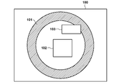
- FIG. 1 shows a configuration example of the wireless power transmission system according to the present embodiment.
- the wireless power transmission system includes a power transmission device 100 and a power reception device 102. It is assumed that the power transmitting device 100 and the power receiving device 102 comply with the WPC (Wireless Power Consortium) standard.
- the power transmission device 100 is, for example, an electronic device that wirelessly transmits power to a power receiving device 102 mounted on its own device.
- the power transmission device 100 wirelessly transmits electric power to the power receiving device 102 via the power transmission coil 101.
- the power receiving device 102 is, for example, an electronic device that receives power from the power transmitting device 100 and charges the built-in battery.
- the power receiving device 102 may be built in other devices (cameras, smartphones, tablet PCs, laptops, automobiles, robots, medical devices, printers) and configured to supply power to those devices.
- the power transmission device 100 may be a smartphone or the like. In this case, for example, the power receiving device 102 may be another smartphone or a wireless earphone. Further, the power receiving device 102 may be a vehicle such as an automobile or a transport aircraft, and the power transmitting device 100 may be a charger installed in a vehicle such as an automobile or a console of a transport aircraft.
- FIG. 1 illustrates a situation in which the conductive foreign matter 103 exists in a range (operating volume) affected by the wireless power output from the power transmission coil 101. If such a foreign substance 103 is present in the operating volume, the efficiency of power transmission / reception deteriorates, and in some cases, problems such as heat generation may occur. Therefore, it is important for the power transmission device 100 and the power reception device 102 to detect such a foreign substance 103 and execute power transmission / reception control. Therefore, in the present embodiment, the power transmission device 100 and the power reception device 102 measure the Q value (Quality factor) from the time change of the voltage inside the power transmission coil within the control range conforming to the WPC standard, and such Foreign matter 103 is detected and power transmission / reception is controlled.
- Q value Quality factor
- the foreign matter 103 is an object different from the power receiving device.
- the foreign matter 103 is, for example, a conductive object such as a metal piece or an IC card.
- FIG. 2 shows a configuration example of the power receiving device 102.
- the power receiving device 102 includes, for example, a control unit 200, a power receiving coil 201, a rectifying unit 202, a voltage control unit 203, a communication unit 204, a charging unit 205, a battery 206, a resonance capacitor 207, and a switch 208.
- the control unit 200 controls the entire power receiving device 102.
- the control unit 200 includes one or more processors such as a CPU (Central Processing Unit) and an MPU (Micro Processing Unit), for example.
- the control unit 200 may include one or more storage devices such as a RAM (Random Access Memory) and a ROM (Read Only Memory), for example.
- the control unit 200 can be configured to execute each of the processes described later by, for example, executing the program stored in the storage device by the processor.
- the power receiving coil 201 is a coil used when receiving electric power from the power transmission coil 101 of the power transmission device 100.
- the rectifying unit 202 converts the AC voltage and AC current received via the power receiving coil 201 into DC voltage and DC current.
- the voltage control unit 203 converts the level of the DC voltage input from the rectifying unit 202 into a level of DC voltage suitable (neither excessive nor too small) for the control unit 200, the charging unit 205, and the like to operate. Further, the voltage control unit 203 supplies the converted level voltage to the charging unit 205.
- the charging unit 205 charges the battery 206 with the voltage supplied from the voltage control unit 203.
- the communication unit 204 performs wireless charging control communication with the power transmission device 100 based on the WPC standard. This control communication is performed by load-modulating the AC voltage and AC current received by the power receiving coil 201.
- the power receiving coil 201 is connected to the resonance capacitor 207 and is configured to resonate at a specific frequency F2.
- the switch 208 is a switch for short-circuiting the power receiving coil 201 and the resonance capacitor 207, and is controlled by the control unit 200.
- the switch 208 is turned on, the power receiving coil 201 and the resonant capacitor 207 form a series resonant circuit.
- the current flows only in the closed circuit of the power receiving coil 201, the resonance capacitor 207, and the switch 208, and the current does not flow in the rectifier unit 202 and the voltage control unit 203.
- the switch 208 is turned off, a current flows through the power receiving coil 201 and the resonance capacitor 207 to the rectifying unit 202 and the voltage control unit 203.
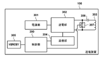
- FIG. 3 shows a configuration example of the power transmission device 100.
- the power transmission device 100 includes, for example, a control unit 300, a power supply unit 301, a power transmission unit 302, a power transmission coil 303, a communication unit 304, a memory 305, a resonance capacitor 306, and a switch 307. Consists of including.
- the control unit 300 controls the entire power transmission device 100.
- the control unit 300 includes one or more processors such as a CPU and an MPU.
- the control unit 300 may be configured to execute each process described later by, for example, executing a program stored in a memory 305 described later or a storage device built in the control unit 300 by a processor.
- the power supply unit 301 supplies power to each functional block.
- the power supply unit 301 is, for example, a commercial power supply or a battery.
- the battery may, for example, store electric power supplied from a commercial power source.
- the power transmission unit 302 converts the DC or AC power input from the power supply unit 301 into AC power in the frequency band used for wireless power transmission, inputs the AC power to the power transmission coil 303, and receives power from the power receiving device 102.
- An electromagnetic wave for causing the electric power is generated from the power transmission coil 303.
- the power transmission unit 302 converts the DC voltage supplied by the power supply unit 301 into an AC voltage by a switching circuit having a half-bridge or full-bridge configuration using a FET (Field Effect Transistor).
- the power transmission unit 302 includes a gate driver that controls ON / OFF of the FET.
- the power transmission unit 302 controls the intensity and frequency of the electromagnetic wave to be output by adjusting at least one of the voltage (transmission voltage) and the current (transmission current) input to the power transmission coil 303, or the frequency.
- the power transmission unit 302 increases the transmission voltage or transmission current to increase the intensity of the electromagnetic wave, and decreases the transmission voltage or transmission current to decrease the intensity of the electromagnetic wave.
- the power transmission unit 302 has an ability to supply electric power sufficient to output 15 watts (W) of electric power to the charging unit 205 of the power receiving device 102 corresponding to the WPC standard.
- the power transmission unit 302 controls the output of AC power so that the output of the electromagnetic wave by the power transmission coil 303 is started or stopped based on the instruction of the control unit 300.
- the communication unit 304 communicates with the power receiving device 102 via the power transmission coil 303 for power transmission control based on the WPC standard.
- the communication unit 304 modulates the AC voltage and AC current output from the transmission unit 302 by using frequency modulation (FSK (Frequency Shift Keying)), and transmits information to the power receiving device 102. Further, the communication unit 304 demodulates the AC voltage and the AC current modulated by the load modulation by the communication unit 204 of the power receiving device 102, and acquires the information transmitted by the power receiving device 102.
- FSK Frequency Shift Keying
- the communication unit 304 superimposes the information to be transmitted to the power receiving device 102 on the electromagnetic wave transmitted from the power transmitting unit 302, and detects the received signal superimposed on the electromagnetic wave by the power receiving device 102 to detect the power receiving device.
- Communicate with 102 the communication unit 304 may use a coil (or antenna) different from the power transmission coil 303 to communicate with the power receiving device 102 according to a standard different from the WPC standard. Further, the communication unit 304 may selectively use a plurality of communication functions to communicate with the power receiving device 102.
- the memory 305 stores, for example, information such as a control program executed by the control unit 300 and the states of the power transmission device 100 and the power reception device 102.
- the state of the power transmission device 100 is acquired by the control unit 300. Further, the state of the power receiving device 102 is acquired by the control unit 200 of the power receiving device 102 and transmitted from the communication unit 205, and the power transmission device 100 acquires information indicating this state via the communication unit 304.
- the power transmission coil 303 is connected to the resonance capacitor 306 and is configured to resonate at a specific frequency F1.
- the switch 307 is a switch for short-circuiting the power transmission coil 303 and the resonance capacitor 306, and is controlled by the control unit 300.
- the switch 307 is turned on, the power transmission coil 303 and the resonant capacitor 306 form a series resonant circuit.
- a current flows only in the closed circuit of the power transmission coil 303, the resonance capacitor 306, and the switch 307.
- the switch 208 is turned off, the power transmission coil 303 and the resonance capacitor 306 are supplied with power from the power transmission unit 302.
- FIG. 4 shows an example of a functional configuration realized by the control unit 300 of the power transmission device 100.
- the control unit 300 includes, for example, a first Q value measurement unit 400, a second Q value measurement unit 401, a calibration processing unit 402, a first foreign matter detection processing unit 403, a second foreign matter detection processing unit 404, and a third foreign matter detection processing unit 405. And can operate as each functional unit of the power transmission processing unit 406.
- the first Q value measuring unit 400 measures the Q value in the frequency domain (first Q value measurement) as described later.
- the second Q value measuring unit 401 measures the Q value in the time domain (second Q value measurement) as described later.
- the Calibration processing unit 402 acquires the Calibration data Point and creates the Calibration curve as described later.
- the first foreign matter detection processing unit 403 executes a foreign matter detection process (first foreign matter detection process) based on the first Q value measured by the first Q value measurement unit 400.
- the second foreign matter detection processing unit 404 executes a foreign matter detection process (second foreign matter detection process) based on the power loss method described later.
- the third foreign matter detection processing unit 405 executes the foreign matter detection process (third foreign matter detection process) based on the second Q value measured by the second Q value measurement unit 401.
- the power transmission processing unit 406 performs processing related to transmission start, transmission stop, and increase / decrease of the transmitted power of the power transmission unit 302.
- Each processing unit shown in FIG. 4 is configured as a plurality of independent programs, and can operate in parallel while synchronizing between the plurality of programs by event processing or the like.
- FIG. 5 shows an example of a functional configuration realized by the control unit 200 of the power receiving device 102.
- the control unit 200 can operate as, for example, each functional unit of the second Q value measuring unit 500 and the power receiving processing unit 501.
- the second Q value measuring unit 500 measures the Q value in the time domain (second Q value measurement) as described later.
- the power receiving processing unit 501 performs processing related to power receiving start, power receiving stop, and power increase / decrease required for the power transmission device 100 of the power receiving device 102.
- Each of the processing units shown in FIG. 5 is configured as an independent program, and can operate in parallel while synchronizing the programs by event processing or the like.
- first foreign matter detection method based on the Q value measured in the frequency domain
- the power transmission device 100 measures the Q value in the frequency domain, which changes due to the influence of the foreign matter (first Q value measurement). This measurement is performed between the transmission of the analog ping by the power transmission device 100 and the transmission of the digital ping (see F601 in FIG. 6A).
- the power transmission unit 302 sweeps the frequency of the radio power output by the power transmission coil 303 in order to measure the Q value
- the first Q value measurement unit 400 is a resonance capacitor connected in series (or in parallel) with the power transmission coil. Measure the voltage value at the end of 306.
- the first Q value measuring unit 400 searches for a resonance frequency at which the voltage value peaks, and obtains a frequency indicating a voltage value that is 3 dB lower than the peak voltage value measured at the resonance frequency and the resonance frequency. Calculate the Q value of the transmission coil 303.
- the Q value may be measured by another method.
- the power transmission unit 302 sweeps the frequency of the radio power output by the power transmission coil 303
- the first Q value measurement unit 400 measures the voltage value at the end of the resonance capacitor 306 connected in series with the power transmission coil 303. , Search for the resonance frequency at which the voltage value peaks. Then, the first Q value measuring unit 400 measures the voltage value across the resonance capacitor 306 at the resonance frequency, and calculates the Q value of the transmission coil 303 from the ratio of the voltage values across the resonance capacitor 306.
- the first foreign matter detection processing unit 403 of the power transmission device 100 After calculating the Q value of the power transmission coil 303, the first foreign matter detection processing unit 403 of the power transmission device 100 acquires the Q value, which is a criterion for determining foreign matter detection, from the power receiving device 102 via the communication unit 304. For example, the first foreign matter detection processing unit 403 receives the Q value (first characteristic value) of the power transmission coil when the power receiving device is placed on the power transmission coil defined by the WPC standard from the power receiving device 102. This Q value is stored in a FOD (Foreign Object Detection) Status packet transmitted by the power receiving device 102, and the power transmission device 100 acquires this Q value by receiving the FOD Status packet.
- FOD Form Object Detection
- the first foreign matter detection processing unit 403 estimates the Q value of the power transmission coil 303 when the power receiving device 102 is placed on the power transmission device 100 from the acquired Q value.
- the estimated Q value is referred to as a first reference Q value.
- the Q value stored in the FOD Status packet can be stored in advance in the non-volatile memory (not shown) of the power receiving device 102. That is, the power receiving device 102 can notify the power transmission device 100 of the Q value stored in advance. This Q value corresponds to Q1 described later.
- the first foreign matter detection processing unit 403 of the power transmission device 100 compares the first reference Q value with the Q value measured by the first Q value measurement unit 400, and determines the presence or absence of foreign matter based on the comparison result. For example, the first foreign matter detection processing unit 403 sets a Q value that is a% (first ratio) lower than the first reference Q value as a threshold value, and when the measured Q value is lower than the threshold value, the foreign matter is found. If not, it is determined that there is a high possibility that there is no foreign matter.
- FIG. 11 is a conceptual diagram of foreign matter detection by the power loss method, in which the horizontal axis shows the power transmitted by the power transmitting device 100 and the vertical axis shows the power received by the power receiving device 102.
- the power transmission by the power transmission unit 302 of the power transmission device 100 can be controlled by the power transmission processing unit 406.
- the power transmission unit 302 of the power transmission device 100 transmits digital pings to the power reception device 102.
- the communication unit 304 of the power transmission device 100 receives the power received power value Pr1 (referred to as Light Load) in the power receiving device 102 by the Received Power Packet (mode 1).
- Pr1 is the received power value when the power receiving device 102 does not supply the received power to the load (charging unit 205, battery 206, etc.).
- the control unit 300 of the power transmission device 100 stores in the memory 305 the relationship between the received Pr1 and the power transmission power value Pt1 when Pr1 is obtained (point 1100 in FIG. 11). Thereby, the power transmission device 100 can recognize that the amount of power loss between the power transmission device 100 and the power receiving device 102 when Pt1 is transmitted as the power transmission power is Pt1-Pr1 (Ploss1).
- the communication unit 304 of the power transmission device 100 receives the value of the power received power value Pr2 (referred to as Connected Load) in the power receiving device 102 from the power receiving device 102 by the Received Power Packet (mode 2).
- the Received Power Packet (mode2) will be referred to as "RP2".
- Pr2 is the received power value when the power receiving device 102 supplies the received power to the load.
- the control unit 300 of the power transmission device 100 stores in the memory 305 the relationship between the received Pr2 and the power transmission power value Pt2 when Pr2 is obtained (point 1101 in FIG. 11). Thereby, the power transmission device 100 can recognize that the amount of power loss between the power transmission device 100 and the power receiving device 102 when Pt2 is transmitted as the power transmission power is Pt2-Pr2 (Ploss2).
- the calibration processing unit 402 of the power transmission device 100 linearly interpolates the points 1100 and 1101 to create a straight line 1102.
- the straight line 1102 corresponds to the relationship between the transmitted power and the received power in a state where no foreign matter is present around the power transmitting device 100 and the power receiving device 102. Therefore, the power transmission device 100 can predict the power received in a state where there is a high possibility that there is no foreign matter from the power transmission value and the straight line 1102. For example, in the case where the transmitted power value is Pt3, the power transmission device 100 can predict that the received power value is Pr3 from the point 1103 on the straight line 1102 corresponding to the case where the transmitted power value is Pt3.
- the communication unit 304 receives a value of the power reception power value Pr3'from the power reception device 102.
- This Plus_FO can be considered as a power loss consumed by the foreign matter when a foreign matter is present between the power transmission device 100 and the power receiving device 102.
- the second foreign matter detection processing unit 404 can determine that the foreign matter is present when the power Plus_FO that would have been consumed by the foreign matter exceeds a predetermined threshold value.
- This threshold value is derived, for example, based on the relationship between the point 1100 and the point 1101.
- the second foreign matter detection processing unit 404 of the power transmission device 100 obtains the power loss amount Pt3-Pr3 (Plus3) between the power transmission device 100 and the power reception device 102 in advance from the power received power value Pr3 in the state where no foreign matter is present. Keep it. Then, the second foreign matter detection processing unit 404 receives power between the power transmission device 100 and the power receiving device 102 in the presence of foreign matter from the received power value Pr3'received from the power receiving device 102 in a state where it is unknown whether or not the foreign matter is present. The amount of loss Pt3-Pr3'(Plus3') is calculated.
- the second foreign matter detection processing unit 404 calculates Pluss3'-Poss3, and when this value exceeds a predetermined threshold value, it can be determined that the foreign matter exists.
- the second foreign matter detection processing unit 404 of the power transmission device 100 After the straight line 1102 is acquired by the calibration processing unit 402, the second foreign matter detection processing unit 404 of the power transmission device 100 periodically transmits the current power received power value (for example, Pr3 described above) from the power receiving device 102 via the communication unit 304. ') Is received.
- the current received power value periodically transmitted by the power receiving device 102 is transmitted to the power transmitting device 100 as a Received Power Packet (mode 0).
- the second foreign matter detection processing unit 404 of the power transmission device 100 detects foreign matter based on the received power value stored in the Received Power Packet (mode 0) and the straight line 1102. In the following, the Received Power Packet (mode0) will be referred to as "RP0".
- the points 1100 and 1101 for acquiring the straight line 1102 which is the relationship between the transmitted power and the received power in a state where no foreign matter exists around the power transmitting device 100 and the power receiving device 102, are referred to as "Calibration data Point”. Called. Further, a line segment (straight line 1102) obtained by interpolating at least two Calibration data points is referred to as a “Calibration curve”. The Calibration data Point and the Calibration curve (second reference) are used for foreign matter detection processing by the second foreign matter detection processing unit 404.
- FIGS. 12A and 12B are conceptual diagrams for explaining a method of measuring a Q value (measurement of a second Q value) in a time domain.
- the foreign matter detecting method based on the second Q value is referred to as a third foreign matter detecting method.
- the second Q value measurement is performed by the second Q value measuring unit 401.
- the power transmission processing unit 406 controls the power transmission by the power transmission unit 302 of the power transmission device 100.
- the power transmission device 100 and the power reception device 102 are switched on during the same period to momentarily interrupt the power transmission and prevent the received power from being delivered to the load. According to this, for example, the voltage applied to the coil gradually decreases. Then, the second Q value is calculated according to the method of this decrease.
- the waveform 1200 in FIG. 12A shows the passage of time of the value of the high frequency voltage (hereinafter, simply referred to as “voltage value of the power transmission coil”) applied to the end of the power transmission coil 303 or the resonance capacitor 306 of the power transmission device 100. ing.
- the horizontal axis represents time and the vertical axis represents voltage value.
- the application of high frequency voltage (power transmission) is stopped.
- Point 1201 is a point on the envelope of the high frequency voltage, which is the high frequency voltage at time T 1.
- T 1 , A 1 ) in FIG. 12A indicates that the voltage value at time T 1 is A 1 .
- point 1202 is a point on the envelope of the high frequency voltage, which is the high frequency voltage at time T 2.
- T 2 , A 2 ) in FIG. 12A indicates that the voltage value at time T 2 is A 2 .
- the Q value measurement is performed based on the time change of the voltage value after the time T 0.
- Waveform 1203 indicates the value of the high frequency voltage applied to the power transmission coil 303, and the frequency is a frequency between 110 kHz and 148.5 kHz used in the Qi standard. Also, points 1204 and 1205 are part of the envelope of the voltage value.
- the power transmission unit 302 of the power transmission device 100 stops power transmission in the section from time T 0 to T 5.
- the 2Q value measuring unit 401 of the power transmission device 100 based on the voltage value A 3 (point 1204) at time T 3, the operating frequency of the voltage value A 4 (point 1205) and the high-frequency voltage at time T 4 (Equation 1) And measure the Q value.
- the power transmission unit 302 of the power transmission apparatus 100 restarts the transmission at time T 5.
- the second Q value measurement is performed by the power transmission device 100 momentarily interrupting the power transmission and measuring the Q value based on the passage of time, the voltage value, and the operating frequency.
- (T 3 , A 3 ) and (T 4 , A 4 ) may be measured, and the second Q value may not be measured.
- T 4 and the value of -T 3 the ratio of A 4 for A 3 (A 4 / A 3 ) or ratio of A 4 of A 3 (A 3 / A 4 )
- the presence or absence of foreign matter may be detected by using an index based on the value. Specifically, the presence or absence of foreign matter may be detected by comparing the index with the threshold value.
- the presence or absence of foreign matter may be detected by measuring the current value instead of the voltage value and using an index based on the ratio of the current values. That is, the current value at T 3 and the current value at time T 4 may be measured. Further, the second Q value may be acquired based on the current value.
- the operation of the conventional power transmission device 100 and the power reception device 102 will be described with reference to FIG. 6A.
- the power transmission device 100 and the power reception device 102 are a power transmission device and a power reception device conforming to the WPC standard v1.2.3, respectively.
- the power transmission device 100 transmits an analog ping to detect an object existing in the vicinity of the power transmission coil 303 (F600).
- Analog Ping is a pulsed electric power, which is an electric power for detecting an object.
- the analog ping is a small amount of electric power that cannot start the control unit 200 even if the electric power receiving device 102 receives the electric power.
- the power transmission device 100 uses Analog Ping to shift the resonance frequency of the voltage value inside the power transmission coil 303 due to an object existing in the vicinity of the power transmission coil 303, and to change the voltage value and current value flowing through the power transmission coil 303. To detect.
- the power transmission device 100 When the power transmission device 100 detects an object by Analog Ping, the power transmission device 100 measures the Q value of the power transmission coil 303 by the above-mentioned first Q value measurement (F601). Then, the power transmission device 100 starts power transmission of Digital Ping following the measurement of the first Q value (F602).
- the Digital Ping is the electric power for activating the control unit 200 of the power receiving device 102, and is a larger electric power than the Analog Ping.
- Digital Ping is continuously transmitted thereafter. That is, the power transmission device 100 continues to transmit power equal to or higher than the Digital Ping from the start of transmission of the Digital Ping (F602) to the reception of the EPT (End Power Transfer) packet described later (F622) from the power receiving device 102.
- the power receiving device 102 When the power receiving device 102 receives power from the Digital Ping and starts up, it stores the voltage value of the received Digital Ping in a Signal Strength packet and transmits it to the power transmission device 100 (F603). Subsequently, the power receiving device 102 transmits an ID packet containing an ID including the version information and device identification information of the WPC standard to which the power receiving device 102 complies to the power transmitting device 100 (F604). Further, the power receiving device 102 transmits a Configuration packet including information such as the maximum value of the electric power supplied to the load (charging unit 205) by the voltage control unit 203 to the power transmission device 100 (F605). The power transmission device 100 receives the ID packet and the Configuration packet. Then, when the power transmission device 100 determines that the power receiving device 102 corresponds to the extended protocol of WPC standard v1.2 or later (including Negotiation described later) by these packets, it responds with ACK (F606).
- ACK ACK
- the power receiving device 102 When the power receiving device 102 receives the ACK, it transitions to the Negotiation phase in which the power to be transmitted and received is negotiated. First, the power receiving device 102 transmits a FOD Status packet to the power transmitting device 100 (F607). In the present embodiment, this FOD Status packet is referred to as "FOD (Q1)".
- the power transmission device 100 uses the first foreign matter detection method based on the Q value (Q value measured in the frequency domain) stored in the received FOD (Q1) and the Q value measured in the first Q value measurement. Perform detection. Then, when it is determined that there is a high possibility that there is no foreign matter, the power transmission device 100 transmits an ACK indicating the determination result to the power receiving device 102 (F608).
- the power receiving device 102 Upon receiving the ACK, the power receiving device 102 negotiates with the Guaranteed Power (GP), which is the maximum value of the power value requested by the power receiving device 102 to receive power.
- the Guaranteed Power indicates the load power (power consumed by the battery 206) of the power receiving device 102 agreed with the power transmitting device 100.
- This negotiation is realized by transmitting a packet containing the requested Guaranteed Power value to the power transmission device 100 from the Special Request specified in the WPC standard (F609). In this embodiment, this packet is referred to as "SRQ (GP)".
- the power transmission device 100 responds to the SRQ (GP) in consideration of the power transmission capacity of the own device and the like.
- the power transmission device 100 determines that the Guaranteed Power is acceptable, it transmits an ACK indicating that the request has been accepted (F610).
- the power receiving device 102 requests 15 watts as a Guaranteed Power by SRQ (GP).
- the power receiving device 102 transmits "SRQ (EN)" requesting the end of the negotiation (End Negotiation) from the Special Request to the power transmission device (F611).
- the power transmission device 100 transmits an ACK to the SRQ (EN) (F612), terminates the negotiation, and transitions to the Power Transfer phase in which the power transmission / reception specified by the Guaranteed Power is performed.
- the power transmission device 100 executes foreign matter detection (second foreign matter detection method) based on the above-mentioned power loss method.
- the power transmission device 100 receives the RP1 from the power reception device 102 (F613).
- the power transmission device 100 receives the power received power value stored in the RP 1 and the power transmission power value of the power transmission device 100 when the received power is obtained as a Calibration data Point (corresponding to the point 1100 in FIG. 11).
- the power transmission device 100 transmits an ACK indicating acceptance of the Calibration data Point to the power reception device 102 (F614).
- the power receiving device 102 After receiving the ACK, the power receiving device 102 transmits to the power transmitting device 100 a Control Error (hereinafter referred to as CE) that requests the power transmitting device 100 to increase or decrease the received voltage (or received current, received power).
- CE Control Error
- a code and a numerical value are stored in the CE. If the code is positive, the power is required to be increased, if the code is negative, the power is required to be decreased, and if the numerical value is zero, the power is requested. Each means demanding maintenance.
- the power receiving device 102 transmits CE (+) indicating that the power is increased to the power transmitting device 100 (F615).
- the power transmission device 100 When the power transmission device 100 receives CE (+), it changes the set value of the power transmission unit 302 to increase the power transmission power (F616). When the received power rises in response to CE (+), the power receiving device 102 supplies the received power to the load (charging unit 205 or battery 206) and transmits RP2 to the power transmitting device 100 (F617). The power transmission device 100 accepts the received power value stored in the RP2 and the power transmission power value of the power transmission device 100 at that time as a Calibration data Point (corresponding to the point 1101 in FIG. 11). Then, the power transmission device 100 transmits an ACK indicating acceptance of the Calibration data Point to the power reception device 102 (F618). At this point, since the power transmission device 100 has acquired two calibration data points (point 1100 and point 1101 in FIG. 11), the calibration curve (straight line 1102 in FIG. 11) can be derived.
- the power transmitting device 100 and the power receiving device 102 have transitioned to the Power Transfer phase at this point, and the power transmitting device 100 is transmitting power capable of receiving a maximum of 15 watts negotiated by the power receiving device 102 in the Negotiation phase.
- the power receiving device 102 periodically transmits the CE requesting the maintenance of the transmitted power and the RP0 storing the current received power value to the power transmitting device 100 (F619, F620).
- the power transmission device 100 detects the foreign matter based on the above-mentioned second foreign matter detection method.
- the power transmission device 100 determines that there is a high possibility that there is no foreign matter as a result of detecting the foreign matter, the power transmission device 100 transmits an ACK to the power receiving device 102 (F621). After that, when the charging of the battery 206 is completed, the power receiving device 102 transmits an EPT (End Power Transfer) packet requesting the power transmission device 100 to stop power transmission (F622).
- EPT End Power Transfer
- wireless power transmission is performed between the power transmitting device 100 and the power receiving device 102 conforming to the WPC standard v1.2.3.
- the Power Transfer phase is a phase in which the TX transmits power, and if there is a foreign substance between the TX and RX during power transmission, heat generation from the foreign substance becomes large.
- the foreign matter detection (first foreign matter detection method) based on the Q value (first Q value) measured in the frequency domain sweeps the frequency in order to search for the resonance frequency at each measurement. If such a sweep is executed while the power transmission device 100 is transmitting a relatively large amount of electric power such as a Digital Ping or a Power Transfer phase, it may cause an increase in switching noise of the power transmission unit 302.
- foreign matter detection (third foreign matter detection method) based on the Q value (second Q value) measured in the time domain can be performed at a single frequency, and there is no need to sweep the frequency. Therefore, it can be executed at the operating frequency at the time of power transmission in the Digital Ping or Power Transfer phase, and the influence on the switching noise is small.
- the switch 208 in the second Q value measurement, when the power transmission device stops power transmission, the switch 208 is turned on to control a closed circuit including the power receiving coil 201 and the resonance capacitor 207. As a result, the second Q value is measured with the influence of the load fluctuation in the power receiving device 102 removed.
- the third foreign matter detection method is applied to the WPC standard, various modes are assumed in the device configuration of the power receiving device 102, so that it is necessary for the power transmission device 100 to appropriately control the processing performed according to the capacity of the power receiving device 102.
- the power transmission device 100 executes the second Q value measurement on the power receiving device 102 that cannot be controlled to form a closed circuit, the measurement is affected by the fluctuation of the load of the power receiving device 102, and the Q value is correctly measured. Can not do it.
- it can be assumed that the measurement of the 2Q value is performed on the power receiving device 102 side, but if the power transmission device 100 does not know the capacity of the power receiving device 102, should the power transmitting device 100 measure the 2Q value in its own device?
- the power receiving device 102 can configure a closed circuit but cannot perform the measurement of the second Q value, the presence or absence of foreign matter cannot be determined unless the power transmission device 100 measures the second Q value. .. Similarly, if the capacity of the power receiving device 102 is not known, the power transmitting device 100 cannot determine whether or not to receive the measurement result of the second Q value from the power receiving device 102. For example, if the power transmitting device 100 tries to receive the measurement result from the power receiving device 102 even though the power receiving device 102 cannot execute the measurement of the second Q value, an unnecessary standby time occurs.
- a control method for appropriately applying the third foreign matter detection method based on the measurement of the second Q value to the WPC standard is used. This control method will be described below.
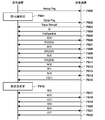
- FIG. 6B shows an example of a processing flow executed by the power transmitting device 100 and the power receiving device 102 according to the present embodiment.
- the same processing as in FIG. 6A is designated by the same reference numerals and the description thereof will be omitted.
- the power receiving device 102 After executing the processes of F600 to F604, the power receiving device 102 transmits the Configuration packet to the power transmission device 100 (F623).
- the capacity information of the power receiving device 102 is notified to the power transmission device 100.
- the Short Ability bit and the Measure Ability bit are defined in the Configuration Packet as the ability information to be notified.
- the Short Availability bit is information indicating whether or not the power receiving device 102 can be controlled to form a closed circuit including the power receiving coil 201 and the resonance capacitor 207 for the second Q value measurement.
- the power receiving device 102 stores, for example, "1" in the Short Availability bit when the own device has the ability to control to form a closed circuit for measuring the second Q value, and "0" otherwise. do.
- the Measure Availability bit is information indicating whether or not the power receiving device 102 can measure the second Q value of the power receiving circuit.
- the power receiving device 102 stores, for example, "1" in the Measurement Availability bit when its own device has the ability to measure the second Q value of the power receiving circuit, and "0" when it does not.
- these pieces of information may be information indicating whether or not the power receiving device 102 can execute a predetermined process associated with the foreign matter determination based on the measurement of the second Q value executed by the power transmission device 100. That is, whether or not the closed circuit can be configured and whether or not the measurement of the second Q value of the power receiving circuit can be performed is only one type of this predetermined process, and the information bits for the other processes are It may be transmitted from the power receiving device 102 to the power transmitting device 100.
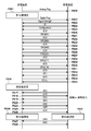
- FIG. 13 shows the configuration of the Configuration Packet of the WPC standard v1.2.3.
- the Configuration Packet of WPC standard v1.2.3 includes a plurality of Reserved regions. That is, the area 1300 from bit0 to bit7 of Bank1, the area 1301 from bit4 to bit6 of Bank2, and the area 1302 from bit0 to bit2 of Bank4 are Reserved regions, respectively.
- the Short Availability bit is arranged in the Bank 4 bit 2
- the Measure Ability bit is arranged in the Bank 4 bit 1.
- these bits may be arranged in another Reserved area.
- the power receiving device 102 may be controlled to form a closed circuit including the power receiving coil 201 and the resonance capacitor 207 for the second Q value measurement, and whether the power receiving device 102 is the power receiving circuit. Whether or not the 2Q value measurement is feasible can be indicated.
- the version-compliant power receiving device 102 it may be specified that the version-compliant power receiving device 102 has these functions.
- the power transmission device 100 can specify whether or not the power receiving device 102 has these functions.
- the bits in the Reserved region described above are all 0. Further, the power transmission device 100 that cannot use the third foreign matter detection method ignores the values stored in these Reserved regions.
- the Short Ability bit and the Measure Ability bit are set in the Configuration Packet and transmitted from the power receiving device 102 to the power transmission device 100 , but the present invention is not limited to this.
- these information may be included in a new packet not specified in the WPC standard and transmitted / received. Further, such information may be included in other packets specified in the WPC standard and transmitted / received.
- the power receiving device 102 can be controlled to form a closed circuit including the power receiving coil 201 and the resonance capacitor 207 for the second Q value measurement, and can execute the measurement of the second Q value of the power receiving circuit.
- the power receiving device 102 transmits a Configuration Packet in which "1" is set in the Short Availability bit and "1" is set in the Measure Availability bit in F623.
- the power transmission device 100 refers to the Short Ability bit and the Measure Ability bit included in the received Configuration Packet, and stores their values in the memory 305.
- the power transmission device 100 responds with an ACK after receiving the Configuration Packet (F606). Then, when the power receiving device 102 receives the ACK for the Configuration Packet, the power receiving device 102 transitions to the Negotiation phase. Then, the power transmission device 100 and the power reception device 102 negotiate on the detection of the third foreign matter in the Negotiation phase. In the second Q value measurement, the power receiving device 102 negotiates the measurement start time, which is the time until the power transmission unit 302 of the power transmission device 100 stops power transmission. This negotiation is performed by the power receiving device 102 transmitting a packet containing the value of the required measurement start time to the power transmission device 100 among the Special Requests specified in the WPC standard (F631).
- the power receiving device 102 determines a required measurement start time value based on its own processing capacity and the like, and transmits a packet containing the measurement start time value to the power transmission device 100.
- this packet is referred to as "SRQ (M1)".
- the power transmission device 100 responds to the SRQ (M1) in consideration of the processing capacity of the own device and the like.
- the power transmission device 100 transmits ACK when it is determined that the measurement start time of the value indicated by SRQ (M1) can be accepted, and NAK when it is determined that the measurement start time cannot be accepted.
- the power transmission device 100 determines that the measurement start time can be accepted and transmits the ACK (F632).
- the power receiving device 102 requests 50 ms as the measurement start time of the Q value in the SRQ (M1).
- the power receiving device 102 negotiates the window length, which is the section length of the section (the section from time T 0 to time T 5 ) in which the power transmission unit 302 of the power transmission device 100 stops power transmission in the second Q value measurement.
- This negotiation is carried out by the power receiving device 102 transmitting a packet containing the required window length value to the power transmission device 100 in the Special Request specified in the WPC standard (F633).
- this packet is referred to as "SRQ (M2)".
- the power receiving device 102 determines a window length value based on the processing capacity of its own device, and transmits a packet containing the determined window length value to the power transmission device 100.
- the power transmission device 100 responds to the SRQ (M2) in consideration of the processing capacity of the own device and the like.
- the power transmission device 100 transmits ACK when it is determined that the window length of the value indicated in SRQ (M2) can be accepted, and NAK when it is determined that the window length cannot be accepted.
- the power transmission device 100 determines that the window length can be accepted and transmits the ACK (F634).
- the power receiving device 102 requests 100 ms as the window length in the SRQ (M2).
- the power receiving device 102 negotiates a timeout length, which is the time for the power transmitting device 100 to receive the Q value measured by the power receiving device 102 in the second Q value measurement from the power receiving device 102.
- This negotiation is performed by the power receiving device 102 transmitting a packet containing the value of the required timeout length from the Special Request specified in the WPC standard to the power transmission device 100 (F635).
- this packet is referred to as "SRQ (M3)".
- the power receiving device 102 determines the value of the timeout length based on the processing capacity of its own device and the like, and transmits a packet containing the value of the time-out length to the power transmission device 100.
- the power transmission device 100 responds to the SRQ (M3) in consideration of the processing capacity of the own device and the like.
- the power transmission device 100 transmits ACK when it is determined that the timeout length can be accepted, and NAK when it is determined that the timeout length cannot be accepted.
- the power transmission device 100 determines that the timeout length can be accepted, and transmits ACK (F636).
- the power receiving device 102 requests a timeout length of 500 ms in the SRQ (M3).
- a type not defined in v1.2.3 of the Specific Request can be assigned to each negotiation of the measurement start time, the window length, and the timeout length.
- the Measurement Delay Req is a packet that requests the power transmission device 100 to change the measurement start time.
- the Window Length Req is a packet that requests the power transmission device 100 to change the window length.
- the Timeout Req is a packet that requests the power transmission device 100 to change the timeout length.
- These three packets are Reserved Packets whose packet types are not specified in WPC standard v1.2.3. In the present embodiment, among these Reserved Packets, a packet having a packet header of 0x40 is defined as a Measure Delay Req packet. Similarly, a packet having a packet header of 0x41 is defined as a Windows Length Req packet, and a packet having a packet header of 0x42 is defined as a Timeout Req packet.
- a packet whose type is not defined, instead of a specific request or a general request may be defined as the above-mentioned three packets.
- a Reserved Packet or Proprietary Packet packet in which a Packet type is undefined, instead of a Specific Request or a General Request can be defined as the above-mentioned three packets.
- the packet in which the Packet type is undefined may be defined as the above-mentioned three packets. That is, a Packet type or a Proprietary Packet whose Packet type is undefined among the General Request and the Special Request can be defined as the above-mentioned three packets.
- the negotiation phase ends and the transition to the Power Transfer phase occurs.
- the above-mentioned processes F613 to F617 are executed.
- the power receiving device 102 transmits the CE requesting the maintenance of the transmitted power and the RP0 storing the current received power value to the power transmitting device 100 to the power transmitting device 100 (F619, F620).
- the power transmission device 100 When the power transmission device 100 receives RP0 from the power receiving device 102, the power transmission device 100 detects foreign matter based on the above-mentioned second foreign matter detection method. As a result of detecting the foreign matter, the power transmission device 100 determines that there is a high possibility that the foreign matter is present, and transmits NAK to the power receiving device 102 (F624). When the power receiving device 102 receives the NAK from the power transmission device 100, the power receiving device 102 transmits Q2R, which is a packet requesting the start of the third foreign substance detection, to the power transmission device 100 in order to measure the presence or absence of foreign matter in more detail (F625).
- Q2R which is a packet requesting the start of the third foreign substance detection
- the Q2R packet is, for example, a packet in which a value indicating that the Q2R packet is set is set in the Reserved bit of the Received Power packet in the WPC standard, but the Q2R packet is not limited to this.
- the power receiving device 102 may request the start of the third foreign matter detection by using the undefined Received Power packet mode, or may request the start of the third foreign matter detection by defining a new packet. good.
- the case where the power receiving device 102 requests the start of the third foreign matter detection by using the Q2R packet is described, but the third foreign matter is triggered by the NAK response to the RP2 without using the Q2R packet. Detection may be initiated.
- the power transmission device 100 When the power transmission device 100 receives the Q2R, it determines whether or not to execute the third foreign matter detection, and if it determines that the third foreign matter detection is executed, it transmits ACK, and if it determines that it does not execute, it transmits NAK to the power receiving device 102. do.
- the power transmission device 100 determines that the third foreign matter is detected. In this case, the power transmission device 100 transmits an ACK to the power reception device 102 (F626).
- the power transmission device 100 and the power receiving device 102 start the third foreign matter detection.
- the power transmission device 100 and the power receiving device 102 measure the second Q value (F629, F630).
- the power receiving device 102 After measuring the second Q value, the power receiving device 102 stores the second Q value measured by the own device in a packet (QRS), and transmits this QRS to the power transmission device 100 (F627).
- the QRS is a packet containing at least the second Q value measured by the power receiving device 102, but may include other information such as the current received power value.
- the power transmission device 100 receives the QRS from the power receiving device 102, the power transmission device 100 determines the presence or absence of foreign matter based on the received 2Q value of the power receiving device 102 and the 2Q value measured by the own device.
- the presence or absence of foreign matter can be determined with higher accuracy.
- the power transmission device 100 determines that there is a foreign substance, it transmits NAK to the power receiving device 102, and when it determines that there is no foreign substance, it transmits ACK to the power receiving device 102.
- the power transmission device 100 determines that there is a foreign substance. In this case, the power transmission device 100 transmits NAK to the power reception device 102 (F628). After that, the power transmission device 100 stops power transmission.
- the power transmission device 100 can execute the control that the power receiving device 102 constitutes a closed circuit including the power receiving coil 201 and the resonance capacitor 207 for the measurement of the second Q value. Is determined (S701).
- the power transmission device 100 refers to, for example, the Short Availability bit saved in the memory in the Configuration phase, and if the value is 1, it is determined that such control is possible (YES in S701), and the process is sent to S702. Proceed.
- the power transmission device 100 determines that such control is not possible (NO in S701), transmits NAK (S708), and ends the process.
- the power transmission device 100 determines in S702 whether or not the power receiving device 102 can measure the second Q value of the power receiving circuit. For example, the power transmission device 100 refers to the Measurement Availability bit saved in the memory in the Configuration phase, and if the value is 0, determines that the measurement of the 2Q value is not possible (NO in S702), and processes the process to S709. Proceed. Then, the power transmission device 100 measures the second Q value in its own device (S709), and proceeds to the process to S706. On the other hand, when the value of the Measurement Ability bit is 1, the power transmission device 100 determines that the measurement of the 2Q value is possible (YES in S702), and proceeds to the process in S703.
- the power transmission device 100 determines in S703 whether or not the own device measures the second Q value of the power transmission circuit. When the power transmission device 100 determines that the own device performs the measurement (YES in S703), the power transmission device 100 executes the measurement of the second Q value (S704), and proceeds to the process in S705. On the other hand, when the power transmission device 100 determines that the own device does not perform the measurement (NO in S703), the power transmission device 100 proceeds to the process in S705 without executing the measurement of the second Q value. In S705, the power transmission device 100 receives the second Q value from the power receiving device and proceeds to process in S706.
- the power transmission device 100 ends the process and stops the power transmission.
- the process can be appropriately advanced or stopped when the second Q value is not sent from the power receiving device 102.
- an appropriate timeout length according to the processing capacity of the power receiving device 102 is determined and set by negotiation as described above, so that even the power receiving device 102 having a low processing capacity can reach the timeout. It becomes possible to complete the transmission of the second Q value.
- the power transmission device 100 determines the presence or absence of foreign matter by using at least one of the 2Q value measured in S704 and the 2Q value received in S705.
- the power transmission device 100 determines that foreign matter is present (YES in S706), it transmits NAK to the power receiving device 102 (S708), while when it is determined that no foreign matter is present (NO in S706), the power receiving device 102 ACK is transmitted to (S707) to end the process.
- the power transmission device 100 confirms that the value of the Short Availability bit is 1 in S701, and determines that the power receiving device 102 can execute the control forming the closed circuit. Then, the process proceeds to S702. Then, the power transmission device 100 confirms that the value of the Measurement Availability bit is 1 in S702, determines that the power receiving device 102 can measure the second Q value, and proceeds to the process in S703. Then, the power transmission device 100 determines in S703 to measure the second Q value also in its own device, and proceeds to the process in S704. The power transmission device 100 measures the second Q value in S704, receives the second Q value measured by the power receiving device 102 in S705, and proceeds to process in S706.
- the power transmission device 100 determines that there is a foreign substance by using the 2Q value received from the power receiving device 102 and the 2Q value measured by the own device in S706, and in S708, the power receiving device 102 NAK is transmitted and the process is terminated.
- the power transmission device 100 determines whether or not the power receiving device 102 can execute the control constituting the closed circuit, so that the power receiving device 102 cannot execute such control. Therefore, it is possible to prevent the measurement of the second Q value. As a result, the power transmission device 100 can prevent erroneous control from being executed by measuring the Q value under inappropriate conditions.
- the power transmission device 100 transmits NAK and ends the process, but this is limited to this. I can't.
- the power transmission device 100 may measure the second Q value in a state where the power receiving device 102 does not form a closed circuit, and determine the presence or absence of foreign matter based on the measured second Q value.
- the 2Q value is measured without forming a closed circuit, it is assumed that the measured value is affected by the fluctuation of the load of the power receiving device.
- the presence or absence of foreign matter is determined by using a standard different from the criterion for determining the presence or absence of foreign matter based on the measurement result of the second Q value when the closed circuit can be configured. Will be done.
- the power transmission device 100 determines whether or not the power reception device 102 has the ability to measure the second Q value of the power transmission circuit. As a result, the power transmission device 100 prevents the foreign matter detection flow from failing because the power receiving device 102 cannot measure the second Q value but the own device does not measure the second Q value. Can be done. Further, the power transmission device 100 prevents the power receiving device 102 from unnecessarily waiting for the measurement result of the second Q value to be sent from the power receiving device 102 even though the power receiving device 102 cannot measure the second Q value. be able to. Further, when the power receiving device 102 can measure the second Q value, the power transmitting device 100 does not receive the second Q value transmitted from the power receiving device 102, and can prevent a state shift from occurring.
- the power transmission device 100 can perform highly accurate foreign matter detection with reduced influence of noise and the like by measuring the second Q value not only in the power receiving device 102 but also in its own device. Further, the power transmission device 100 omits the measurement of the second Q value in the own device by determining in S703 that the own device does not measure the second Q value, and uses the second Q value received from the power receiving device 102. It is possible to judge foreign matter. According to this, it is possible to suppress the occurrence of unnecessary measurement due to the simultaneous measurement of the Q value by the power transmission device 100 and the power reception device 102.
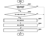
- the power receiving device 102 determines whether or not the power receiving device 102 can be controlled to form a closed circuit including the power receiving coil 201 and the resonance capacitor 207 for the measurement of the second Q value (S801).
- the process proceeds to S802, and when it is determined that the control for forming the closed circuit is not possible (NO in S801). The process proceeds to S805.
- the power receiving device 102 determines whether or not the own device can measure the second Q value of the power receiving circuit. Then, when the power receiving device 102 can measure the second Q value (YES in S802), the process proceeds to S803, and when the measurement of the second Q value is not possible (NO in S802), the process is changed to S805. Proceed.
- the power receiving device 102 measures the second Q value in S803, then transmits the Q value measured in S803 in S804 to the power transmission device 100, and proceeds to the process in S805. Then, in S805, the power receiving device 102 receives the result of foreign matter detection from the power transmission device 100 and ends the process.
- the power receiving device 102 determines in S801 that the power receiving device 102 can control to form a closed circuit including the power receiving coil 201 and the resonance capacitor 207 for the measurement of the second Q value. Further, the power receiving device 102 determines in S802 that the own device can measure the second Q value of the power receiving circuit. Then, the power receiving device 102 executes the processes from S803 to S805, and ends the process of FIG.
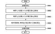
- the power transmission device 100 stops power transmission within 50 ms, which is the value negotiated in the negotiation of the measurement start time, after the transmission of the ACK is completed by, for example, F626 (the transmission of the rear end in the time domain of the ACK is completed). (S901).
- the power transmission device 100 measures the voltage value A 3 of the power transmission coil at time T 3 (S902), also measures the voltage value A 4 of the power transmission coil at time T 4 (S903).
- the power transmission device 100 calculates the Q value from the operating frequency, the measurement time, and the voltage value as described above (S904). Then, the power transmission device 100 resumes power transmission (S905) after a lapse of 100 ms or more, which is a value negotiated in the negotiation of the window length, from the stop of power transmission in S901, and ends the process.
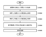
- the power receiving device 102 detects that the power transmission is stopped within 50 ms, which is the value negotiated in the negotiation of the measurement start time, after the reception of the ACK is completed by F626 (the rear end in the time domain of the ACK is received). do. Then, the power receiving device 102 executes control for forming a closed circuit including the power receiving coil 201 and the resonance capacitor 207 (S1001).
- the power receiving device 102 measures the voltage value A 3 of the power receiving coil at time T 3 (S1002), and measures the voltage value A 4 of the power receiving coil at time T 4 (S1003). Then, the power receiving device 102 calculates the Q value from the operating frequency, the measurement time, and the voltage value (S1004). After that, the power receiving device 102 reconnects the load (S1005) before 100 ms, which is the value negotiated in the window length negotiation, elapses from the stop of power transmission detected in S1001, and ends the process. The load is reconnected by turning off the switch 208.
- FIGS. 7 to 10 can be realized, for example, by the control unit 300 of the power transmission device 100 or the control unit 200 of the power receiving device 102 reading and executing a program stored in advance.
- the present invention is not limited to this, and at least a part of these processes may be realized by hardware.
- a dedicated circuit can be automatically generated on the FPGA from the program for realizing each processing step.
- FPGA is an acronym for Field Programmable Gate Array.
- a Gate Array circuit may be formed so that hardware that executes at least a part of the above-mentioned processing can be realized.
- the power receiving device 102 can recognize the timing when the power transmission device 100 stops the power transmission, and can appropriately start the measurement of the second Q value. ..
- the measurement of the second Q value is started at a timing suitable for the power receiving device 102. You will be able to. For example, when it is necessary to transmit another packet near the time when the power receiving device 102 measures the 2Q value, the measurement start time is negotiated so that the 2Q value measurement can be completed before the packet transmission starts. sell.
- the power transmission device 100 can stop the power transmission at the timing when the power receiving device 102 completes the configuration of the closed circuit and the like and can start the measurement process of the second Q value.
- the power receiving device 102 can reconnect the power receiving coil 201 to the load at an appropriate timing. That is, if power transmission is restarted in the power receiving device 102 while the closed circuit is configured, an excessive current may flow through the power receiving coil 201 and the resonance capacitor 207.
- the window length is determined in advance by negotiation, it is possible to prevent such a situation from occurring.
- the time required for measuring the second Q value may differ depending on the performance of the power receiving device 102 and the required measurement accuracy.
- the power receiving device 102 of the present embodiment secures a sufficient measurement period by negotiating the window length according to the performance of the own device and the required measurement accuracy, and causes a measurement failure or measurement. It is possible to prevent a decrease in accuracy.
- the measurement start timing, the measurement period length, and the period (time-out time) until the measurement report of the 2Q value in the power receiving device are all determined by negotiation. At least one of the above may be negotiated. That is, for example, only one of these negotiations may be carried out, or only two of these negotiations may be carried out. That is, these elements may be used independently of each other, and not all of them must always be used.
- the present invention supplies a program that realizes one or more functions of the above-described embodiment to a system or device via a network or storage medium, and one or more processors in the computer of the system or device reads and executes the program. It can also be realized by the processing to be performed. It can also be realized by a circuit (for example, ASIC) that realizes one or more functions.
- a circuit for example, ASIC
Landscapes
- Engineering & Computer Science (AREA)
- Power Engineering (AREA)
- Computer Networks & Wireless Communication (AREA)
- Physics & Mathematics (AREA)
- General Physics & Mathematics (AREA)
- General Engineering & Computer Science (AREA)
- Charge And Discharge Circuits For Batteries Or The Like (AREA)
Priority Applications (7)
| Application Number | Priority Date | Filing Date | Title |
|---|---|---|---|
| CN202180026730.7A CN115428298B (zh) | 2020-03-31 | 2021-03-03 | 送电设备、受电设备、控制方法和计算机可读存储介质 |
| EP21781832.7A EP4131723A4 (en) | 2020-03-31 | 2021-03-03 | POWER TRANSMISSION DEVICE, POWER RECEIVING DEVICE, CONTROL METHOD AND PROGRAM |
| KR1020227036328A KR102805037B1 (ko) | 2020-03-31 | 2021-03-03 | 송전 장치, 수전 장치, 제어 방법, 및 컴퓨터-판독가능 저장 매체 |
| CN202510891992.XA CN120638685A (zh) | 2020-03-31 | 2021-03-03 | 送电设备、送电设备所用的方法、存储介质和计算机程序产品 |
| KR1020257014438A KR20250069967A (ko) | 2020-03-31 | 2021-03-03 | 송전 장치, 송전 장치를 위한 방법, 및 비일시적 컴퓨터-판독가능한 저장 매체 |
| US17/935,417 US12074456B2 (en) | 2020-03-31 | 2022-09-26 | Power transmission apparatus, power reception apparatus, control method, and computer-readable storage medium |
| US18/774,183 US20240372409A1 (en) | 2020-03-31 | 2024-07-16 | Power transmission apparatus, power reception apparatus, control method, and computer-readable storage medium |
Applications Claiming Priority (2)
| Application Number | Priority Date | Filing Date | Title |
|---|---|---|---|
| JP2020-064204 | 2020-03-31 | ||
| JP2020064204A JP7536489B2 (ja) | 2020-03-31 | 2020-03-31 | 送電装置、受電装置、制御方法、およびプログラム |
Related Child Applications (1)
| Application Number | Title | Priority Date | Filing Date |
|---|---|---|---|
| US17/935,417 Continuation US12074456B2 (en) | 2020-03-31 | 2022-09-26 | Power transmission apparatus, power reception apparatus, control method, and computer-readable storage medium |
Publications (1)
| Publication Number | Publication Date |
|---|---|
| WO2021199867A1 true WO2021199867A1 (ja) | 2021-10-07 |
Family
ID=77930297
Family Applications (1)
| Application Number | Title | Priority Date | Filing Date |
|---|---|---|---|
| PCT/JP2021/008184 Ceased WO2021199867A1 (ja) | 2020-03-31 | 2021-03-03 | 送電装置、受電装置、制御方法、およびプログラム |
Country Status (6)
| Country | Link |
|---|---|
| US (2) | US12074456B2 (enExample) |
| EP (1) | EP4131723A4 (enExample) |
| JP (2) | JP7536489B2 (enExample) |
| KR (2) | KR102805037B1 (enExample) |
| CN (2) | CN120638685A (enExample) |
| WO (1) | WO2021199867A1 (enExample) |
Families Citing this family (4)
| Publication number | Priority date | Publication date | Assignee | Title |
|---|---|---|---|---|
| EP4156457A4 (en) * | 2020-05-22 | 2024-06-19 | LG Electronics, Inc. | Wireless power transmission device, wireless power transmission method by wireless power transmission device, wireless power reception device, and wireless power reception method by wireless power reception device |
| US11081911B1 (en) * | 2020-08-21 | 2021-08-03 | Apple Inc. | Enhanced wireless power transfer |
| WO2022211443A1 (ko) * | 2021-03-29 | 2022-10-06 | 엘지전자 주식회사 | 무선 전력 전송 시스템에서 보정 방법 및 장치 |
| US20230163635A1 (en) * | 2021-11-19 | 2023-05-25 | Samsung Electronics Co., Ltd. | Wireless power transmission device and operating method of wireless power transmitter |
Citations (5)
| Publication number | Priority date | Publication date | Assignee | Title |
|---|---|---|---|---|
| JP5071574B1 (ja) * | 2011-07-05 | 2012-11-14 | ソニー株式会社 | 検知装置、受電装置、非接触電力伝送システム及び検知方法 |
| JP2013027255A (ja) * | 2011-07-25 | 2013-02-04 | Sony Corp | 検知装置、受電装置、送電装置、非接触電力伝送システム及び検知方法 |
| JP2018133993A (ja) * | 2013-08-28 | 2018-08-23 | ソニー株式会社 | 給電装置、受電装置、給電システム、および、給電装置の制御方法 |
| JP2019097383A (ja) * | 2019-01-09 | 2019-06-20 | ソニー株式会社 | 受電装置及び電力伝送システム |
| JP2020064204A (ja) | 2018-10-18 | 2020-04-23 | ショーボンド建設株式会社 | 吸音構造体及び吸音構造体の設置方法 |
Family Cites Families (25)
| Publication number | Priority date | Publication date | Assignee | Title |
|---|---|---|---|---|
| JP2010104097A (ja) * | 2008-10-21 | 2010-05-06 | Seiko Epson Corp | 認証処理装置、送電装置、受電装置、及び電子機器 |
| JP2012135127A (ja) | 2010-12-22 | 2012-07-12 | Panasonic Corp | 無線電力伝送システム、それに用いられる送電機器および受電機器、ならびに無線電力伝送方法 |
| TWI570427B (zh) * | 2015-10-28 | 2017-02-11 | 富達通科技股份有限公司 | 感應式電源供應器及其金屬異物檢測方法 |
| JP2013070580A (ja) * | 2011-09-26 | 2013-04-18 | Sony Corp | 受電装置、送電装置、非接触電力伝送システム及び非接触電力伝送方法 |
| JP6029278B2 (ja) | 2011-12-21 | 2016-11-24 | ソニー株式会社 | 受電装置及び非接触電力伝送システム |
| JP6019581B2 (ja) * | 2011-12-26 | 2016-11-02 | ソニー株式会社 | 検知装置、検知システム、送電装置、非接触電力伝送システム及び検知方法 |
| JP6172263B2 (ja) | 2013-03-26 | 2017-08-02 | 富士通株式会社 | 無線電力伝送システムおよび無線電力伝送方法 |
| JP6392550B2 (ja) * | 2014-02-10 | 2018-09-19 | ローム株式会社 | ワイヤレス受電装置およびその制御回路、それを用いた電子機器、異常検出方法 |
| JP6497614B2 (ja) * | 2014-05-26 | 2019-04-10 | パナソニックIpマネジメント株式会社 | 送電装置及び無線電力伝送システム |
| CN105226843B (zh) * | 2014-05-27 | 2017-09-15 | 松下知识产权经营株式会社 | 无线电力传输系统以及无线电力传输系统的送电装置 |
| CN106410991B (zh) | 2015-07-30 | 2021-08-27 | 松下知识产权经营株式会社 | 异物检测装置、无线送电装置以及无线电力传输系统 |
| CN106451815B (zh) * | 2015-08-06 | 2021-06-11 | 松下知识产权经营株式会社 | 送电装置以及无线功率传输系统 |
| JP6632299B2 (ja) | 2015-09-29 | 2020-01-22 | ローム株式会社 | ワイヤレス送電装置、その制御回路、充電器、およびパワーロスメソッドによる異物検出のキャリブレーション方法 |
| CN109314404A (zh) * | 2016-06-06 | 2019-02-05 | 富士通株式会社 | 电力传输系统 |
| US11070095B2 (en) * | 2016-07-01 | 2021-07-20 | Lg Innotek Co., Ltd. | Method for detecting foreign material, and device and system therefor |
| WO2018020876A1 (ja) * | 2016-07-29 | 2018-02-01 | ソニーセミコンダクタソリューションズ株式会社 | 給電装置 |
| WO2018093099A1 (ko) | 2016-11-15 | 2018-05-24 | 엘지전자(주) | 무선 전력 전달 방법 및 이를 위한 장치 |
| KR101897646B1 (ko) | 2017-01-09 | 2018-09-12 | 엘지이노텍 주식회사 | 무선 충전 장치 및 그 방법 |
| JP2018117483A (ja) * | 2017-01-20 | 2018-07-26 | キヤノン株式会社 | 給電装置、制御方法及びプログラム |
| JP7037276B2 (ja) | 2017-02-08 | 2022-03-16 | キヤノン株式会社 | 受電装置、送電装置、方法、及びプログラム |
| US10770921B2 (en) * | 2017-02-10 | 2020-09-08 | Apple Inc. | Wireless charging system with start-up negotiation |
| KR102719208B1 (ko) | 2017-11-02 | 2024-10-21 | 엘지이노텍 주식회사 | 무선 충전 방법 및 그를 위한 장치 |
| JP7121521B2 (ja) * | 2018-04-06 | 2022-08-18 | キヤノン株式会社 | 受電装置、送電装置、無線電力伝送システムおよびそれらの制御方法 |
| WO2019221532A1 (ko) * | 2018-05-16 | 2019-11-21 | 엘지이노텍(주) | 무선 전력 전송 제어 방법 및 장치 |
| KR20200028593A (ko) | 2018-09-07 | 2020-03-17 | 엘지이노텍 주식회사 | 무선 전력 전송 방법 및 장치 |
-
2020
- 2020-03-31 JP JP2020064204A patent/JP7536489B2/ja active Active
-
2021
- 2021-03-03 KR KR1020227036328A patent/KR102805037B1/ko active Active
- 2021-03-03 CN CN202510891992.XA patent/CN120638685A/zh active Pending
- 2021-03-03 CN CN202180026730.7A patent/CN115428298B/zh active Active
- 2021-03-03 EP EP21781832.7A patent/EP4131723A4/en active Pending
- 2021-03-03 WO PCT/JP2021/008184 patent/WO2021199867A1/ja not_active Ceased
- 2021-03-03 KR KR1020257014438A patent/KR20250069967A/ko active Pending
-
2022
- 2022-09-26 US US17/935,417 patent/US12074456B2/en active Active
-
2024
- 2024-07-16 US US18/774,183 patent/US20240372409A1/en active Pending
- 2024-08-05 JP JP2024129115A patent/JP7756766B2/ja active Active
Patent Citations (5)
| Publication number | Priority date | Publication date | Assignee | Title |
|---|---|---|---|---|
| JP5071574B1 (ja) * | 2011-07-05 | 2012-11-14 | ソニー株式会社 | 検知装置、受電装置、非接触電力伝送システム及び検知方法 |
| JP2013027255A (ja) * | 2011-07-25 | 2013-02-04 | Sony Corp | 検知装置、受電装置、送電装置、非接触電力伝送システム及び検知方法 |
| JP2018133993A (ja) * | 2013-08-28 | 2018-08-23 | ソニー株式会社 | 給電装置、受電装置、給電システム、および、給電装置の制御方法 |
| JP2020064204A (ja) | 2018-10-18 | 2020-04-23 | ショーボンド建設株式会社 | 吸音構造体及び吸音構造体の設置方法 |
| JP2019097383A (ja) * | 2019-01-09 | 2019-06-20 | ソニー株式会社 | 受電装置及び電力伝送システム |
Non-Patent Citations (1)
| Title |
|---|
| See also references of EP4131723A4 |
Also Published As
| Publication number | Publication date |
|---|---|
| CN115428298A (zh) | 2022-12-02 |
| JP7756766B2 (ja) | 2025-10-20 |
| US20240372409A1 (en) | 2024-11-07 |
| JP2021164283A (ja) | 2021-10-11 |
| CN120638685A (zh) | 2025-09-12 |
| KR102805037B1 (ko) | 2025-05-12 |
| JP2024149690A (ja) | 2024-10-18 |
| EP4131723A4 (en) | 2024-11-06 |
| US12074456B2 (en) | 2024-08-27 |
| CN115428298B (zh) | 2025-07-18 |
| JP7536489B2 (ja) | 2024-08-20 |
| US20230198315A1 (en) | 2023-06-22 |
| KR20220156885A (ko) | 2022-11-28 |
| EP4131723A1 (en) | 2023-02-08 |
| KR20250069967A (ko) | 2025-05-20 |
Similar Documents
| Publication | Publication Date | Title |
|---|---|---|
| WO2021199867A1 (ja) | 送電装置、受電装置、制御方法、およびプログラム | |
| US12470091B2 (en) | Power transmission apparatus, power receiving apparatus, control methods thereof, and storage medium | |
| US12395013B2 (en) | Power transmission apparatus, power reception apparatus, method, and storage medium | |
| US12142943B2 (en) | Power reception apparatus, control method, and computer-readable storage medium | |
| US20240333041A1 (en) | Power receiving apparatus, method for power receiving apparatus, and storage medium | |
| EP4510423A1 (en) | Power-receiving device and method for controlling same, power-feeding device and method for controlling same, program, and storage medium | |
| JP2021164284A (ja) | 送電装置、受電装置、制御方法、およびプログラム | |
| JP7749402B2 (ja) | 受電装置、送電装置、無線電力伝送方法、及び、プログラム | |
| JP2023156217A (ja) | 受電装置およびその制御方法、送電装置およびその制御方法、プログラム | |
| JP2023016438A (ja) | 受電装置、受電装置の制御方法およびプログラム | |
| JP2022135516A (ja) | 送電装置、送電装置の制御方法、及び、プログラム | |
| JP2023073802A (ja) | 受電装置、無線電力伝送システムおよび受電装置の制御方法 | |
| CN117597853A (zh) | 送电设备、受电设备、无线送电方法和程序 |
Legal Events
| Date | Code | Title | Description |
|---|---|---|---|
| 121 | Ep: the epo has been informed by wipo that ep was designated in this application |
Ref document number: 21781832 Country of ref document: EP Kind code of ref document: A1 |
|
| ENP | Entry into the national phase |
Ref document number: 20227036328 Country of ref document: KR Kind code of ref document: A |
|
| NENP | Non-entry into the national phase |
Ref country code: DE |
|
| ENP | Entry into the national phase |
Ref document number: 2021781832 Country of ref document: EP Effective date: 20221031 |
|
| WWG | Wipo information: grant in national office |
Ref document number: 202180026730.7 Country of ref document: CN |