WO2021199867A1 - 送電装置、受電装置、制御方法、およびプログラム - Google Patents
送電装置、受電装置、制御方法、およびプログラム Download PDFInfo
- Publication number
- WO2021199867A1 WO2021199867A1 PCT/JP2021/008184 JP2021008184W WO2021199867A1 WO 2021199867 A1 WO2021199867 A1 WO 2021199867A1 JP 2021008184 W JP2021008184 W JP 2021008184W WO 2021199867 A1 WO2021199867 A1 WO 2021199867A1
- Authority
- WO
- WIPO (PCT)
- Prior art keywords
- power
- power receiving
- value
- power transmission
- receiving device
- Prior art date
Links
Images


Classifications
-
- G—PHYSICS
- G01—MEASURING; TESTING
- G01R—MEASURING ELECTRIC VARIABLES; MEASURING MAGNETIC VARIABLES
- G01R31/00—Arrangements for testing electric properties; Arrangements for locating electric faults; Arrangements for electrical testing characterised by what is being tested not provided for elsewhere
- G01R31/28—Testing of electronic circuits, e.g. by signal tracer
- G01R31/282—Testing of electronic circuits specially adapted for particular applications not provided for elsewhere
- G01R31/2822—Testing of electronic circuits specially adapted for particular applications not provided for elsewhere of microwave or radiofrequency circuits
- G01R31/2824—Testing of electronic circuits specially adapted for particular applications not provided for elsewhere of microwave or radiofrequency circuits testing of oscillators or resonators
-
- H—ELECTRICITY
- H02—GENERATION; CONVERSION OR DISTRIBUTION OF ELECTRIC POWER
- H02J—CIRCUIT ARRANGEMENTS OR SYSTEMS FOR SUPPLYING OR DISTRIBUTING ELECTRIC POWER; SYSTEMS FOR STORING ELECTRIC ENERGY
- H02J50/00—Circuit arrangements or systems for wireless supply or distribution of electric power
- H02J50/60—Circuit arrangements or systems for wireless supply or distribution of electric power responsive to the presence of foreign objects, e.g. detection of living beings
-
- G—PHYSICS
- G01—MEASURING; TESTING
- G01R—MEASURING ELECTRIC VARIABLES; MEASURING MAGNETIC VARIABLES
- G01R19/00—Arrangements for measuring currents or voltages or for indicating presence or sign thereof
- G01R19/12—Measuring rate of change
-
- H—ELECTRICITY
- H02—GENERATION; CONVERSION OR DISTRIBUTION OF ELECTRIC POWER
- H02J—CIRCUIT ARRANGEMENTS OR SYSTEMS FOR SUPPLYING OR DISTRIBUTING ELECTRIC POWER; SYSTEMS FOR STORING ELECTRIC ENERGY
- H02J50/00—Circuit arrangements or systems for wireless supply or distribution of electric power
- H02J50/10—Circuit arrangements or systems for wireless supply or distribution of electric power using inductive coupling
- H02J50/12—Circuit arrangements or systems for wireless supply or distribution of electric power using inductive coupling of the resonant type
-
- H—ELECTRICITY
- H02—GENERATION; CONVERSION OR DISTRIBUTION OF ELECTRIC POWER
- H02J—CIRCUIT ARRANGEMENTS OR SYSTEMS FOR SUPPLYING OR DISTRIBUTING ELECTRIC POWER; SYSTEMS FOR STORING ELECTRIC ENERGY
- H02J50/00—Circuit arrangements or systems for wireless supply or distribution of electric power
- H02J50/80—Circuit arrangements or systems for wireless supply or distribution of electric power involving the exchange of data, concerning supply or distribution of electric power, between transmitting devices and receiving devices
-
- H—ELECTRICITY
- H02—GENERATION; CONVERSION OR DISTRIBUTION OF ELECTRIC POWER
- H02J—CIRCUIT ARRANGEMENTS OR SYSTEMS FOR SUPPLYING OR DISTRIBUTING ELECTRIC POWER; SYSTEMS FOR STORING ELECTRIC ENERGY
- H02J7/00—Circuit arrangements for charging or depolarising batteries or for supplying loads from batteries
- H02J7/00032—Circuit arrangements for charging or depolarising batteries or for supplying loads from batteries characterised by data exchange
- H02J7/00034—Charger exchanging data with an electronic device, i.e. telephone, whose internal battery is under charge
Definitions
- the present invention relates to a power transmission device, a power receiving device, a control method, and a program, and more particularly to a foreign matter detection technique in wireless power transmission.
- Patent Document 1 describes a method of detecting a foreign substance and limiting power transmission / reception when a foreign substance is present in the vicinity of a power transmission / reception device conforming to the WPC standard.
- Patent Document 2 discloses a technique for detecting foreign matter by short-circuiting the coil of a wireless power transmission system.
- Patent Document 3 describes a technique for detecting a foreign substance by changing the Q value (Quality factor) of the coil measured by applying a high frequency signal to the power transmission coil of the wireless power transmission system for a certain period of time.
- the present invention provides a technique for enabling more accurate detection of an object different from the power receiving device in a power transmitting device and a power receiving device conforming to the WPC standard.
- the power transmission device is a power transmission means that wirelessly transmits power to the power reception device via a power transmission coil, a communication means that communicates with the power reception device, and a phase in which power is transmitted from the power transmission device to the power reception device.
- Q of the power transmission coil based on information indicating whether or not the power receiving device can perform a predetermined process related to determination of the presence or absence of an object different from the power receiving device based on the measurement of the Q value of the power transmission coil. It has a control means for controlling whether or not to execute determination of the presence or absence of an object different from the power receiving device based on the measurement of the value.
- the present invention in a power transmitting device and a power receiving device conforming to the WPC standard, it is possible to detect an object different from the power receiving device with higher accuracy.
- FIG. 1 is a diagram showing a configuration example of a wireless power transmission system.
- FIG. 2 is a diagram showing a configuration example of the power receiving device.
- FIG. 3 is a diagram showing a configuration example of a power transmission device.
- FIG. 4 is a diagram showing an example of a functional configuration of a control unit of a power transmission device.
- FIG. 5 is a diagram showing an example of a functional configuration of a control unit of a power receiving device.
- FIG. 6A is a diagram showing an example of a processing flow executed by a conventional power transmitting device and a power receiving device.
- FIG. 1 is a diagram showing a configuration example of a wireless power transmission system.
- FIG. 2 is a diagram showing a configuration example of the power receiving device.
- FIG. 3 is a diagram showing a configuration example of a power transmission device.
- FIG. 4 is a diagram showing an example of a functional configuration of a control unit of a power transmission device.
- FIG. 5 is a diagram
- FIG. 6B is a diagram showing an example of a processing flow executed by the power transmitting device and the power receiving device according to the embodiment.
- FIG. 7 is a diagram showing an example of the flow of the third foreign matter detection process by the power transmission device.
- FIG. 8 is a diagram showing an example of the flow of the third foreign matter detection process by the power receiving device.
- FIG. 9 is a diagram showing an example of a flow of measurement processing of the second Q value by the power transmission device.
- FIG. 10 is a diagram showing an example of a flow of measurement processing of the second Q value by the power receiving device.
- FIG. 11 is a diagram illustrating foreign matter detection by the power loss method.
- FIG. 12A is a diagram illustrating a method of measuring the Q value in the time domain.
- FIG. 12B is a diagram illustrating a method of measuring the Q value in the time domain.
- FIG. 13 is a diagram showing a frame format of the Configuration Packet.
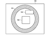
- FIG. 1 shows a configuration example of the wireless power transmission system according to the present embodiment.
- the wireless power transmission system includes a power transmission device 100 and a power reception device 102. It is assumed that the power transmitting device 100 and the power receiving device 102 comply with the WPC (Wireless Power Consortium) standard.
- the power transmission device 100 is, for example, an electronic device that wirelessly transmits power to a power receiving device 102 mounted on its own device.
- the power transmission device 100 wirelessly transmits electric power to the power receiving device 102 via the power transmission coil 101.
- the power receiving device 102 is, for example, an electronic device that receives power from the power transmitting device 100 and charges the built-in battery.
- the power receiving device 102 may be built in other devices (cameras, smartphones, tablet PCs, laptops, automobiles, robots, medical devices, printers) and configured to supply power to those devices.
- the power transmission device 100 may be a smartphone or the like. In this case, for example, the power receiving device 102 may be another smartphone or a wireless earphone. Further, the power receiving device 102 may be a vehicle such as an automobile or a transport aircraft, and the power transmitting device 100 may be a charger installed in a vehicle such as an automobile or a console of a transport aircraft.
- FIG. 1 illustrates a situation in which the conductive foreign matter 103 exists in a range (operating volume) affected by the wireless power output from the power transmission coil 101. If such a foreign substance 103 is present in the operating volume, the efficiency of power transmission / reception deteriorates, and in some cases, problems such as heat generation may occur. Therefore, it is important for the power transmission device 100 and the power reception device 102 to detect such a foreign substance 103 and execute power transmission / reception control. Therefore, in the present embodiment, the power transmission device 100 and the power reception device 102 measure the Q value (Quality factor) from the time change of the voltage inside the power transmission coil within the control range conforming to the WPC standard, and such Foreign matter 103 is detected and power transmission / reception is controlled.
- Q value Quality factor
- the foreign matter 103 is an object different from the power receiving device.
- the foreign matter 103 is, for example, a conductive object such as a metal piece or an IC card.
- FIG. 2 shows a configuration example of the power receiving device 102.
- the power receiving device 102 includes, for example, a control unit 200, a power receiving coil 201, a rectifying unit 202, a voltage control unit 203, a communication unit 204, a charging unit 205, a battery 206, a resonance capacitor 207, and a switch 208.
- the control unit 200 controls the entire power receiving device 102.
- the control unit 200 includes one or more processors such as a CPU (Central Processing Unit) and an MPU (Micro Processing Unit), for example.
- the control unit 200 may include one or more storage devices such as a RAM (Random Access Memory) and a ROM (Read Only Memory), for example.
- the control unit 200 can be configured to execute each of the processes described later by, for example, executing the program stored in the storage device by the processor.
- the power receiving coil 201 is a coil used when receiving electric power from the power transmission coil 101 of the power transmission device 100.
- the rectifying unit 202 converts the AC voltage and AC current received via the power receiving coil 201 into DC voltage and DC current.
- the voltage control unit 203 converts the level of the DC voltage input from the rectifying unit 202 into a level of DC voltage suitable (neither excessive nor too small) for the control unit 200, the charging unit 205, and the like to operate. Further, the voltage control unit 203 supplies the converted level voltage to the charging unit 205.
- the charging unit 205 charges the battery 206 with the voltage supplied from the voltage control unit 203.
- the communication unit 204 performs wireless charging control communication with the power transmission device 100 based on the WPC standard. This control communication is performed by load-modulating the AC voltage and AC current received by the power receiving coil 201.
- the power receiving coil 201 is connected to the resonance capacitor 207 and is configured to resonate at a specific frequency F2.
- the switch 208 is a switch for short-circuiting the power receiving coil 201 and the resonance capacitor 207, and is controlled by the control unit 200.
- the switch 208 is turned on, the power receiving coil 201 and the resonant capacitor 207 form a series resonant circuit.
- the current flows only in the closed circuit of the power receiving coil 201, the resonance capacitor 207, and the switch 208, and the current does not flow in the rectifier unit 202 and the voltage control unit 203.
- the switch 208 is turned off, a current flows through the power receiving coil 201 and the resonance capacitor 207 to the rectifying unit 202 and the voltage control unit 203.
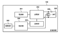
- FIG. 3 shows a configuration example of the power transmission device 100.
- the power transmission device 100 includes, for example, a control unit 300, a power supply unit 301, a power transmission unit 302, a power transmission coil 303, a communication unit 304, a memory 305, a resonance capacitor 306, and a switch 307. Consists of including.
- the control unit 300 controls the entire power transmission device 100.
- the control unit 300 includes one or more processors such as a CPU and an MPU.
- the control unit 300 may be configured to execute each process described later by, for example, executing a program stored in a memory 305 described later or a storage device built in the control unit 300 by a processor.
- the power supply unit 301 supplies power to each functional block.
- the power supply unit 301 is, for example, a commercial power supply or a battery.
- the battery may, for example, store electric power supplied from a commercial power source.
- the power transmission unit 302 converts the DC or AC power input from the power supply unit 301 into AC power in the frequency band used for wireless power transmission, inputs the AC power to the power transmission coil 303, and receives power from the power receiving device 102.
- An electromagnetic wave for causing the electric power is generated from the power transmission coil 303.
- the power transmission unit 302 converts the DC voltage supplied by the power supply unit 301 into an AC voltage by a switching circuit having a half-bridge or full-bridge configuration using a FET (Field Effect Transistor).
- the power transmission unit 302 includes a gate driver that controls ON / OFF of the FET.
- the power transmission unit 302 controls the intensity and frequency of the electromagnetic wave to be output by adjusting at least one of the voltage (transmission voltage) and the current (transmission current) input to the power transmission coil 303, or the frequency.
- the power transmission unit 302 increases the transmission voltage or transmission current to increase the intensity of the electromagnetic wave, and decreases the transmission voltage or transmission current to decrease the intensity of the electromagnetic wave.
- the power transmission unit 302 has an ability to supply electric power sufficient to output 15 watts (W) of electric power to the charging unit 205 of the power receiving device 102 corresponding to the WPC standard.
- the power transmission unit 302 controls the output of AC power so that the output of the electromagnetic wave by the power transmission coil 303 is started or stopped based on the instruction of the control unit 300.
- the communication unit 304 communicates with the power receiving device 102 via the power transmission coil 303 for power transmission control based on the WPC standard.
- the communication unit 304 modulates the AC voltage and AC current output from the transmission unit 302 by using frequency modulation (FSK (Frequency Shift Keying)), and transmits information to the power receiving device 102. Further, the communication unit 304 demodulates the AC voltage and the AC current modulated by the load modulation by the communication unit 204 of the power receiving device 102, and acquires the information transmitted by the power receiving device 102.
- FSK Frequency Shift Keying
- the communication unit 304 superimposes the information to be transmitted to the power receiving device 102 on the electromagnetic wave transmitted from the power transmitting unit 302, and detects the received signal superimposed on the electromagnetic wave by the power receiving device 102 to detect the power receiving device.
- Communicate with 102 the communication unit 304 may use a coil (or antenna) different from the power transmission coil 303 to communicate with the power receiving device 102 according to a standard different from the WPC standard. Further, the communication unit 304 may selectively use a plurality of communication functions to communicate with the power receiving device 102.
- the memory 305 stores, for example, information such as a control program executed by the control unit 300 and the states of the power transmission device 100 and the power reception device 102.
- the state of the power transmission device 100 is acquired by the control unit 300. Further, the state of the power receiving device 102 is acquired by the control unit 200 of the power receiving device 102 and transmitted from the communication unit 205, and the power transmission device 100 acquires information indicating this state via the communication unit 304.
- the power transmission coil 303 is connected to the resonance capacitor 306 and is configured to resonate at a specific frequency F1.
- the switch 307 is a switch for short-circuiting the power transmission coil 303 and the resonance capacitor 306, and is controlled by the control unit 300.
- the switch 307 is turned on, the power transmission coil 303 and the resonant capacitor 306 form a series resonant circuit.
- a current flows only in the closed circuit of the power transmission coil 303, the resonance capacitor 306, and the switch 307.
- the switch 208 is turned off, the power transmission coil 303 and the resonance capacitor 306 are supplied with power from the power transmission unit 302.
- FIG. 4 shows an example of a functional configuration realized by the control unit 300 of the power transmission device 100.
- the control unit 300 includes, for example, a first Q value measurement unit 400, a second Q value measurement unit 401, a calibration processing unit 402, a first foreign matter detection processing unit 403, a second foreign matter detection processing unit 404, and a third foreign matter detection processing unit 405. And can operate as each functional unit of the power transmission processing unit 406.
- the first Q value measuring unit 400 measures the Q value in the frequency domain (first Q value measurement) as described later.
- the second Q value measuring unit 401 measures the Q value in the time domain (second Q value measurement) as described later.
- the Calibration processing unit 402 acquires the Calibration data Point and creates the Calibration curve as described later.
- the first foreign matter detection processing unit 403 executes a foreign matter detection process (first foreign matter detection process) based on the first Q value measured by the first Q value measurement unit 400.
- the second foreign matter detection processing unit 404 executes a foreign matter detection process (second foreign matter detection process) based on the power loss method described later.
- the third foreign matter detection processing unit 405 executes the foreign matter detection process (third foreign matter detection process) based on the second Q value measured by the second Q value measurement unit 401.
- the power transmission processing unit 406 performs processing related to transmission start, transmission stop, and increase / decrease of the transmitted power of the power transmission unit 302.
- Each processing unit shown in FIG. 4 is configured as a plurality of independent programs, and can operate in parallel while synchronizing between the plurality of programs by event processing or the like.
- FIG. 5 shows an example of a functional configuration realized by the control unit 200 of the power receiving device 102.
- the control unit 200 can operate as, for example, each functional unit of the second Q value measuring unit 500 and the power receiving processing unit 501.
- the second Q value measuring unit 500 measures the Q value in the time domain (second Q value measurement) as described later.
- the power receiving processing unit 501 performs processing related to power receiving start, power receiving stop, and power increase / decrease required for the power transmission device 100 of the power receiving device 102.
- Each of the processing units shown in FIG. 5 is configured as an independent program, and can operate in parallel while synchronizing the programs by event processing or the like.
- first foreign matter detection method based on the Q value measured in the frequency domain
- the power transmission device 100 measures the Q value in the frequency domain, which changes due to the influence of the foreign matter (first Q value measurement). This measurement is performed between the transmission of the analog ping by the power transmission device 100 and the transmission of the digital ping (see F601 in FIG. 6A).
- the power transmission unit 302 sweeps the frequency of the radio power output by the power transmission coil 303 in order to measure the Q value
- the first Q value measurement unit 400 is a resonance capacitor connected in series (or in parallel) with the power transmission coil. Measure the voltage value at the end of 306.
- the first Q value measuring unit 400 searches for a resonance frequency at which the voltage value peaks, and obtains a frequency indicating a voltage value that is 3 dB lower than the peak voltage value measured at the resonance frequency and the resonance frequency. Calculate the Q value of the transmission coil 303.
- the Q value may be measured by another method.
- the power transmission unit 302 sweeps the frequency of the radio power output by the power transmission coil 303
- the first Q value measurement unit 400 measures the voltage value at the end of the resonance capacitor 306 connected in series with the power transmission coil 303. , Search for the resonance frequency at which the voltage value peaks. Then, the first Q value measuring unit 400 measures the voltage value across the resonance capacitor 306 at the resonance frequency, and calculates the Q value of the transmission coil 303 from the ratio of the voltage values across the resonance capacitor 306.
- the first foreign matter detection processing unit 403 of the power transmission device 100 After calculating the Q value of the power transmission coil 303, the first foreign matter detection processing unit 403 of the power transmission device 100 acquires the Q value, which is a criterion for determining foreign matter detection, from the power receiving device 102 via the communication unit 304. For example, the first foreign matter detection processing unit 403 receives the Q value (first characteristic value) of the power transmission coil when the power receiving device is placed on the power transmission coil defined by the WPC standard from the power receiving device 102. This Q value is stored in a FOD (Foreign Object Detection) Status packet transmitted by the power receiving device 102, and the power transmission device 100 acquires this Q value by receiving the FOD Status packet.
- FOD Form Object Detection
- the first foreign matter detection processing unit 403 estimates the Q value of the power transmission coil 303 when the power receiving device 102 is placed on the power transmission device 100 from the acquired Q value.
- the estimated Q value is referred to as a first reference Q value.
- the Q value stored in the FOD Status packet can be stored in advance in the non-volatile memory (not shown) of the power receiving device 102. That is, the power receiving device 102 can notify the power transmission device 100 of the Q value stored in advance. This Q value corresponds to Q1 described later.
- the first foreign matter detection processing unit 403 of the power transmission device 100 compares the first reference Q value with the Q value measured by the first Q value measurement unit 400, and determines the presence or absence of foreign matter based on the comparison result. For example, the first foreign matter detection processing unit 403 sets a Q value that is a% (first ratio) lower than the first reference Q value as a threshold value, and when the measured Q value is lower than the threshold value, the foreign matter is found. If not, it is determined that there is a high possibility that there is no foreign matter.
- FIG. 11 is a conceptual diagram of foreign matter detection by the power loss method, in which the horizontal axis shows the power transmitted by the power transmitting device 100 and the vertical axis shows the power received by the power receiving device 102.
- the power transmission by the power transmission unit 302 of the power transmission device 100 can be controlled by the power transmission processing unit 406.
- the power transmission unit 302 of the power transmission device 100 transmits digital pings to the power reception device 102.
- the communication unit 304 of the power transmission device 100 receives the power received power value Pr1 (referred to as Light Load) in the power receiving device 102 by the Received Power Packet (mode 1).
- Pr1 is the received power value when the power receiving device 102 does not supply the received power to the load (charging unit 205, battery 206, etc.).
- the control unit 300 of the power transmission device 100 stores in the memory 305 the relationship between the received Pr1 and the power transmission power value Pt1 when Pr1 is obtained (point 1100 in FIG. 11). Thereby, the power transmission device 100 can recognize that the amount of power loss between the power transmission device 100 and the power receiving device 102 when Pt1 is transmitted as the power transmission power is Pt1-Pr1 (Ploss1).
- the communication unit 304 of the power transmission device 100 receives the value of the power received power value Pr2 (referred to as Connected Load) in the power receiving device 102 from the power receiving device 102 by the Received Power Packet (mode 2).
- the Received Power Packet (mode2) will be referred to as "RP2".
- Pr2 is the received power value when the power receiving device 102 supplies the received power to the load.
- the control unit 300 of the power transmission device 100 stores in the memory 305 the relationship between the received Pr2 and the power transmission power value Pt2 when Pr2 is obtained (point 1101 in FIG. 11). Thereby, the power transmission device 100 can recognize that the amount of power loss between the power transmission device 100 and the power receiving device 102 when Pt2 is transmitted as the power transmission power is Pt2-Pr2 (Ploss2).
- the calibration processing unit 402 of the power transmission device 100 linearly interpolates the points 1100 and 1101 to create a straight line 1102.
- the straight line 1102 corresponds to the relationship between the transmitted power and the received power in a state where no foreign matter is present around the power transmitting device 100 and the power receiving device 102. Therefore, the power transmission device 100 can predict the power received in a state where there is a high possibility that there is no foreign matter from the power transmission value and the straight line 1102. For example, in the case where the transmitted power value is Pt3, the power transmission device 100 can predict that the received power value is Pr3 from the point 1103 on the straight line 1102 corresponding to the case where the transmitted power value is Pt3.
- the communication unit 304 receives a value of the power reception power value Pr3'from the power reception device 102.
- This Plus_FO can be considered as a power loss consumed by the foreign matter when a foreign matter is present between the power transmission device 100 and the power receiving device 102.
- the second foreign matter detection processing unit 404 can determine that the foreign matter is present when the power Plus_FO that would have been consumed by the foreign matter exceeds a predetermined threshold value.
- This threshold value is derived, for example, based on the relationship between the point 1100 and the point 1101.
- the second foreign matter detection processing unit 404 of the power transmission device 100 obtains the power loss amount Pt3-Pr3 (Plus3) between the power transmission device 100 and the power reception device 102 in advance from the power received power value Pr3 in the state where no foreign matter is present. Keep it. Then, the second foreign matter detection processing unit 404 receives power between the power transmission device 100 and the power receiving device 102 in the presence of foreign matter from the received power value Pr3'received from the power receiving device 102 in a state where it is unknown whether or not the foreign matter is present. The amount of loss Pt3-Pr3'(Plus3') is calculated.
- the second foreign matter detection processing unit 404 calculates Pluss3'-Poss3, and when this value exceeds a predetermined threshold value, it can be determined that the foreign matter exists.
- the second foreign matter detection processing unit 404 of the power transmission device 100 After the straight line 1102 is acquired by the calibration processing unit 402, the second foreign matter detection processing unit 404 of the power transmission device 100 periodically transmits the current power received power value (for example, Pr3 described above) from the power receiving device 102 via the communication unit 304. ') Is received.
- the current received power value periodically transmitted by the power receiving device 102 is transmitted to the power transmitting device 100 as a Received Power Packet (mode 0).
- the second foreign matter detection processing unit 404 of the power transmission device 100 detects foreign matter based on the received power value stored in the Received Power Packet (mode 0) and the straight line 1102. In the following, the Received Power Packet (mode0) will be referred to as "RP0".
- the points 1100 and 1101 for acquiring the straight line 1102 which is the relationship between the transmitted power and the received power in a state where no foreign matter exists around the power transmitting device 100 and the power receiving device 102, are referred to as "Calibration data Point”. Called. Further, a line segment (straight line 1102) obtained by interpolating at least two Calibration data points is referred to as a “Calibration curve”. The Calibration data Point and the Calibration curve (second reference) are used for foreign matter detection processing by the second foreign matter detection processing unit 404.
- FIGS. 12A and 12B are conceptual diagrams for explaining a method of measuring a Q value (measurement of a second Q value) in a time domain.
- the foreign matter detecting method based on the second Q value is referred to as a third foreign matter detecting method.
- the second Q value measurement is performed by the second Q value measuring unit 401.
- the power transmission processing unit 406 controls the power transmission by the power transmission unit 302 of the power transmission device 100.
- the power transmission device 100 and the power reception device 102 are switched on during the same period to momentarily interrupt the power transmission and prevent the received power from being delivered to the load. According to this, for example, the voltage applied to the coil gradually decreases. Then, the second Q value is calculated according to the method of this decrease.
- the waveform 1200 in FIG. 12A shows the passage of time of the value of the high frequency voltage (hereinafter, simply referred to as “voltage value of the power transmission coil”) applied to the end of the power transmission coil 303 or the resonance capacitor 306 of the power transmission device 100. ing.
- the horizontal axis represents time and the vertical axis represents voltage value.
- the application of high frequency voltage (power transmission) is stopped.
- Point 1201 is a point on the envelope of the high frequency voltage, which is the high frequency voltage at time T 1.
- T 1 , A 1 ) in FIG. 12A indicates that the voltage value at time T 1 is A 1 .
- point 1202 is a point on the envelope of the high frequency voltage, which is the high frequency voltage at time T 2.
- T 2 , A 2 ) in FIG. 12A indicates that the voltage value at time T 2 is A 2 .
- the Q value measurement is performed based on the time change of the voltage value after the time T 0.
- Waveform 1203 indicates the value of the high frequency voltage applied to the power transmission coil 303, and the frequency is a frequency between 110 kHz and 148.5 kHz used in the Qi standard. Also, points 1204 and 1205 are part of the envelope of the voltage value.
- the power transmission unit 302 of the power transmission device 100 stops power transmission in the section from time T 0 to T 5.
- the 2Q value measuring unit 401 of the power transmission device 100 based on the voltage value A 3 (point 1204) at time T 3, the operating frequency of the voltage value A 4 (point 1205) and the high-frequency voltage at time T 4 (Equation 1) And measure the Q value.
- the power transmission unit 302 of the power transmission apparatus 100 restarts the transmission at time T 5.
- the second Q value measurement is performed by the power transmission device 100 momentarily interrupting the power transmission and measuring the Q value based on the passage of time, the voltage value, and the operating frequency.
- (T 3 , A 3 ) and (T 4 , A 4 ) may be measured, and the second Q value may not be measured.
- T 4 and the value of -T 3 the ratio of A 4 for A 3 (A 4 / A 3 ) or ratio of A 4 of A 3 (A 3 / A 4 )
- the presence or absence of foreign matter may be detected by using an index based on the value. Specifically, the presence or absence of foreign matter may be detected by comparing the index with the threshold value.
- the presence or absence of foreign matter may be detected by measuring the current value instead of the voltage value and using an index based on the ratio of the current values. That is, the current value at T 3 and the current value at time T 4 may be measured. Further, the second Q value may be acquired based on the current value.
- the operation of the conventional power transmission device 100 and the power reception device 102 will be described with reference to FIG. 6A.
- the power transmission device 100 and the power reception device 102 are a power transmission device and a power reception device conforming to the WPC standard v1.2.3, respectively.
- the power transmission device 100 transmits an analog ping to detect an object existing in the vicinity of the power transmission coil 303 (F600).
- Analog Ping is a pulsed electric power, which is an electric power for detecting an object.
- the analog ping is a small amount of electric power that cannot start the control unit 200 even if the electric power receiving device 102 receives the electric power.
- the power transmission device 100 uses Analog Ping to shift the resonance frequency of the voltage value inside the power transmission coil 303 due to an object existing in the vicinity of the power transmission coil 303, and to change the voltage value and current value flowing through the power transmission coil 303. To detect.
- the power transmission device 100 When the power transmission device 100 detects an object by Analog Ping, the power transmission device 100 measures the Q value of the power transmission coil 303 by the above-mentioned first Q value measurement (F601). Then, the power transmission device 100 starts power transmission of Digital Ping following the measurement of the first Q value (F602).
- the Digital Ping is the electric power for activating the control unit 200 of the power receiving device 102, and is a larger electric power than the Analog Ping.
- Digital Ping is continuously transmitted thereafter. That is, the power transmission device 100 continues to transmit power equal to or higher than the Digital Ping from the start of transmission of the Digital Ping (F602) to the reception of the EPT (End Power Transfer) packet described later (F622) from the power receiving device 102.
- the power receiving device 102 When the power receiving device 102 receives power from the Digital Ping and starts up, it stores the voltage value of the received Digital Ping in a Signal Strength packet and transmits it to the power transmission device 100 (F603). Subsequently, the power receiving device 102 transmits an ID packet containing an ID including the version information and device identification information of the WPC standard to which the power receiving device 102 complies to the power transmitting device 100 (F604). Further, the power receiving device 102 transmits a Configuration packet including information such as the maximum value of the electric power supplied to the load (charging unit 205) by the voltage control unit 203 to the power transmission device 100 (F605). The power transmission device 100 receives the ID packet and the Configuration packet. Then, when the power transmission device 100 determines that the power receiving device 102 corresponds to the extended protocol of WPC standard v1.2 or later (including Negotiation described later) by these packets, it responds with ACK (F606).
- ACK ACK
- the power receiving device 102 When the power receiving device 102 receives the ACK, it transitions to the Negotiation phase in which the power to be transmitted and received is negotiated. First, the power receiving device 102 transmits a FOD Status packet to the power transmitting device 100 (F607). In the present embodiment, this FOD Status packet is referred to as "FOD (Q1)".
- the power transmission device 100 uses the first foreign matter detection method based on the Q value (Q value measured in the frequency domain) stored in the received FOD (Q1) and the Q value measured in the first Q value measurement. Perform detection. Then, when it is determined that there is a high possibility that there is no foreign matter, the power transmission device 100 transmits an ACK indicating the determination result to the power receiving device 102 (F608).
- the power receiving device 102 Upon receiving the ACK, the power receiving device 102 negotiates with the Guaranteed Power (GP), which is the maximum value of the power value requested by the power receiving device 102 to receive power.
- the Guaranteed Power indicates the load power (power consumed by the battery 206) of the power receiving device 102 agreed with the power transmitting device 100.
- This negotiation is realized by transmitting a packet containing the requested Guaranteed Power value to the power transmission device 100 from the Special Request specified in the WPC standard (F609). In this embodiment, this packet is referred to as "SRQ (GP)".
- the power transmission device 100 responds to the SRQ (GP) in consideration of the power transmission capacity of the own device and the like.
- the power transmission device 100 determines that the Guaranteed Power is acceptable, it transmits an ACK indicating that the request has been accepted (F610).
- the power receiving device 102 requests 15 watts as a Guaranteed Power by SRQ (GP).
- the power receiving device 102 transmits "SRQ (EN)" requesting the end of the negotiation (End Negotiation) from the Special Request to the power transmission device (F611).
- the power transmission device 100 transmits an ACK to the SRQ (EN) (F612), terminates the negotiation, and transitions to the Power Transfer phase in which the power transmission / reception specified by the Guaranteed Power is performed.
- the power transmission device 100 executes foreign matter detection (second foreign matter detection method) based on the above-mentioned power loss method.
- the power transmission device 100 receives the RP1 from the power reception device 102 (F613).
- the power transmission device 100 receives the power received power value stored in the RP 1 and the power transmission power value of the power transmission device 100 when the received power is obtained as a Calibration data Point (corresponding to the point 1100 in FIG. 11).
- the power transmission device 100 transmits an ACK indicating acceptance of the Calibration data Point to the power reception device 102 (F614).
- the power receiving device 102 After receiving the ACK, the power receiving device 102 transmits to the power transmitting device 100 a Control Error (hereinafter referred to as CE) that requests the power transmitting device 100 to increase or decrease the received voltage (or received current, received power).
- CE Control Error
- a code and a numerical value are stored in the CE. If the code is positive, the power is required to be increased, if the code is negative, the power is required to be decreased, and if the numerical value is zero, the power is requested. Each means demanding maintenance.
- the power receiving device 102 transmits CE (+) indicating that the power is increased to the power transmitting device 100 (F615).
- the power transmission device 100 When the power transmission device 100 receives CE (+), it changes the set value of the power transmission unit 302 to increase the power transmission power (F616). When the received power rises in response to CE (+), the power receiving device 102 supplies the received power to the load (charging unit 205 or battery 206) and transmits RP2 to the power transmitting device 100 (F617). The power transmission device 100 accepts the received power value stored in the RP2 and the power transmission power value of the power transmission device 100 at that time as a Calibration data Point (corresponding to the point 1101 in FIG. 11). Then, the power transmission device 100 transmits an ACK indicating acceptance of the Calibration data Point to the power reception device 102 (F618). At this point, since the power transmission device 100 has acquired two calibration data points (point 1100 and point 1101 in FIG. 11), the calibration curve (straight line 1102 in FIG. 11) can be derived.
- the power transmitting device 100 and the power receiving device 102 have transitioned to the Power Transfer phase at this point, and the power transmitting device 100 is transmitting power capable of receiving a maximum of 15 watts negotiated by the power receiving device 102 in the Negotiation phase.
- the power receiving device 102 periodically transmits the CE requesting the maintenance of the transmitted power and the RP0 storing the current received power value to the power transmitting device 100 (F619, F620).
- the power transmission device 100 detects the foreign matter based on the above-mentioned second foreign matter detection method.
- the power transmission device 100 determines that there is a high possibility that there is no foreign matter as a result of detecting the foreign matter, the power transmission device 100 transmits an ACK to the power receiving device 102 (F621). After that, when the charging of the battery 206 is completed, the power receiving device 102 transmits an EPT (End Power Transfer) packet requesting the power transmission device 100 to stop power transmission (F622).
- EPT End Power Transfer
- wireless power transmission is performed between the power transmitting device 100 and the power receiving device 102 conforming to the WPC standard v1.2.3.
- the Power Transfer phase is a phase in which the TX transmits power, and if there is a foreign substance between the TX and RX during power transmission, heat generation from the foreign substance becomes large.
- the foreign matter detection (first foreign matter detection method) based on the Q value (first Q value) measured in the frequency domain sweeps the frequency in order to search for the resonance frequency at each measurement. If such a sweep is executed while the power transmission device 100 is transmitting a relatively large amount of electric power such as a Digital Ping or a Power Transfer phase, it may cause an increase in switching noise of the power transmission unit 302.
- foreign matter detection (third foreign matter detection method) based on the Q value (second Q value) measured in the time domain can be performed at a single frequency, and there is no need to sweep the frequency. Therefore, it can be executed at the operating frequency at the time of power transmission in the Digital Ping or Power Transfer phase, and the influence on the switching noise is small.
- the switch 208 in the second Q value measurement, when the power transmission device stops power transmission, the switch 208 is turned on to control a closed circuit including the power receiving coil 201 and the resonance capacitor 207. As a result, the second Q value is measured with the influence of the load fluctuation in the power receiving device 102 removed.
- the third foreign matter detection method is applied to the WPC standard, various modes are assumed in the device configuration of the power receiving device 102, so that it is necessary for the power transmission device 100 to appropriately control the processing performed according to the capacity of the power receiving device 102.
- the power transmission device 100 executes the second Q value measurement on the power receiving device 102 that cannot be controlled to form a closed circuit, the measurement is affected by the fluctuation of the load of the power receiving device 102, and the Q value is correctly measured. Can not do it.
- it can be assumed that the measurement of the 2Q value is performed on the power receiving device 102 side, but if the power transmission device 100 does not know the capacity of the power receiving device 102, should the power transmitting device 100 measure the 2Q value in its own device?
- the power receiving device 102 can configure a closed circuit but cannot perform the measurement of the second Q value, the presence or absence of foreign matter cannot be determined unless the power transmission device 100 measures the second Q value. .. Similarly, if the capacity of the power receiving device 102 is not known, the power transmitting device 100 cannot determine whether or not to receive the measurement result of the second Q value from the power receiving device 102. For example, if the power transmitting device 100 tries to receive the measurement result from the power receiving device 102 even though the power receiving device 102 cannot execute the measurement of the second Q value, an unnecessary standby time occurs.
- a control method for appropriately applying the third foreign matter detection method based on the measurement of the second Q value to the WPC standard is used. This control method will be described below.
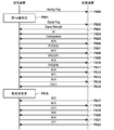
- FIG. 6B shows an example of a processing flow executed by the power transmitting device 100 and the power receiving device 102 according to the present embodiment.
- the same processing as in FIG. 6A is designated by the same reference numerals and the description thereof will be omitted.
- the power receiving device 102 After executing the processes of F600 to F604, the power receiving device 102 transmits the Configuration packet to the power transmission device 100 (F623).
- the capacity information of the power receiving device 102 is notified to the power transmission device 100.
- the Short Ability bit and the Measure Ability bit are defined in the Configuration Packet as the ability information to be notified.
- the Short Availability bit is information indicating whether or not the power receiving device 102 can be controlled to form a closed circuit including the power receiving coil 201 and the resonance capacitor 207 for the second Q value measurement.
- the power receiving device 102 stores, for example, "1" in the Short Availability bit when the own device has the ability to control to form a closed circuit for measuring the second Q value, and "0" otherwise. do.
- the Measure Availability bit is information indicating whether or not the power receiving device 102 can measure the second Q value of the power receiving circuit.
- the power receiving device 102 stores, for example, "1" in the Measurement Availability bit when its own device has the ability to measure the second Q value of the power receiving circuit, and "0" when it does not.
- these pieces of information may be information indicating whether or not the power receiving device 102 can execute a predetermined process associated with the foreign matter determination based on the measurement of the second Q value executed by the power transmission device 100. That is, whether or not the closed circuit can be configured and whether or not the measurement of the second Q value of the power receiving circuit can be performed is only one type of this predetermined process, and the information bits for the other processes are It may be transmitted from the power receiving device 102 to the power transmitting device 100.
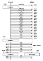
- FIG. 13 shows the configuration of the Configuration Packet of the WPC standard v1.2.3.
- the Configuration Packet of WPC standard v1.2.3 includes a plurality of Reserved regions. That is, the area 1300 from bit0 to bit7 of Bank1, the area 1301 from bit4 to bit6 of Bank2, and the area 1302 from bit0 to bit2 of Bank4 are Reserved regions, respectively.
- the Short Availability bit is arranged in the Bank 4 bit 2
- the Measure Ability bit is arranged in the Bank 4 bit 1.
- these bits may be arranged in another Reserved area.
- the power receiving device 102 may be controlled to form a closed circuit including the power receiving coil 201 and the resonance capacitor 207 for the second Q value measurement, and whether the power receiving device 102 is the power receiving circuit. Whether or not the 2Q value measurement is feasible can be indicated.
- the version-compliant power receiving device 102 it may be specified that the version-compliant power receiving device 102 has these functions.
- the power transmission device 100 can specify whether or not the power receiving device 102 has these functions.
- the bits in the Reserved region described above are all 0. Further, the power transmission device 100 that cannot use the third foreign matter detection method ignores the values stored in these Reserved regions.
- the Short Ability bit and the Measure Ability bit are set in the Configuration Packet and transmitted from the power receiving device 102 to the power transmission device 100 , but the present invention is not limited to this.
- these information may be included in a new packet not specified in the WPC standard and transmitted / received. Further, such information may be included in other packets specified in the WPC standard and transmitted / received.
- the power receiving device 102 can be controlled to form a closed circuit including the power receiving coil 201 and the resonance capacitor 207 for the second Q value measurement, and can execute the measurement of the second Q value of the power receiving circuit.
- the power receiving device 102 transmits a Configuration Packet in which "1" is set in the Short Availability bit and "1" is set in the Measure Availability bit in F623.
- the power transmission device 100 refers to the Short Ability bit and the Measure Ability bit included in the received Configuration Packet, and stores their values in the memory 305.
- the power transmission device 100 responds with an ACK after receiving the Configuration Packet (F606). Then, when the power receiving device 102 receives the ACK for the Configuration Packet, the power receiving device 102 transitions to the Negotiation phase. Then, the power transmission device 100 and the power reception device 102 negotiate on the detection of the third foreign matter in the Negotiation phase. In the second Q value measurement, the power receiving device 102 negotiates the measurement start time, which is the time until the power transmission unit 302 of the power transmission device 100 stops power transmission. This negotiation is performed by the power receiving device 102 transmitting a packet containing the value of the required measurement start time to the power transmission device 100 among the Special Requests specified in the WPC standard (F631).
- the power receiving device 102 determines a required measurement start time value based on its own processing capacity and the like, and transmits a packet containing the measurement start time value to the power transmission device 100.
- this packet is referred to as "SRQ (M1)".
- the power transmission device 100 responds to the SRQ (M1) in consideration of the processing capacity of the own device and the like.
- the power transmission device 100 transmits ACK when it is determined that the measurement start time of the value indicated by SRQ (M1) can be accepted, and NAK when it is determined that the measurement start time cannot be accepted.
- the power transmission device 100 determines that the measurement start time can be accepted and transmits the ACK (F632).
- the power receiving device 102 requests 50 ms as the measurement start time of the Q value in the SRQ (M1).
- the power receiving device 102 negotiates the window length, which is the section length of the section (the section from time T 0 to time T 5 ) in which the power transmission unit 302 of the power transmission device 100 stops power transmission in the second Q value measurement.
- This negotiation is carried out by the power receiving device 102 transmitting a packet containing the required window length value to the power transmission device 100 in the Special Request specified in the WPC standard (F633).
- this packet is referred to as "SRQ (M2)".
- the power receiving device 102 determines a window length value based on the processing capacity of its own device, and transmits a packet containing the determined window length value to the power transmission device 100.
- the power transmission device 100 responds to the SRQ (M2) in consideration of the processing capacity of the own device and the like.
- the power transmission device 100 transmits ACK when it is determined that the window length of the value indicated in SRQ (M2) can be accepted, and NAK when it is determined that the window length cannot be accepted.
- the power transmission device 100 determines that the window length can be accepted and transmits the ACK (F634).
- the power receiving device 102 requests 100 ms as the window length in the SRQ (M2).
- the power receiving device 102 negotiates a timeout length, which is the time for the power transmitting device 100 to receive the Q value measured by the power receiving device 102 in the second Q value measurement from the power receiving device 102.
- This negotiation is performed by the power receiving device 102 transmitting a packet containing the value of the required timeout length from the Special Request specified in the WPC standard to the power transmission device 100 (F635).
- this packet is referred to as "SRQ (M3)".
- the power receiving device 102 determines the value of the timeout length based on the processing capacity of its own device and the like, and transmits a packet containing the value of the time-out length to the power transmission device 100.
- the power transmission device 100 responds to the SRQ (M3) in consideration of the processing capacity of the own device and the like.
- the power transmission device 100 transmits ACK when it is determined that the timeout length can be accepted, and NAK when it is determined that the timeout length cannot be accepted.
- the power transmission device 100 determines that the timeout length can be accepted, and transmits ACK (F636).
- the power receiving device 102 requests a timeout length of 500 ms in the SRQ (M3).
- a type not defined in v1.2.3 of the Specific Request can be assigned to each negotiation of the measurement start time, the window length, and the timeout length.
- the Measurement Delay Req is a packet that requests the power transmission device 100 to change the measurement start time.
- the Window Length Req is a packet that requests the power transmission device 100 to change the window length.
- the Timeout Req is a packet that requests the power transmission device 100 to change the timeout length.
- These three packets are Reserved Packets whose packet types are not specified in WPC standard v1.2.3. In the present embodiment, among these Reserved Packets, a packet having a packet header of 0x40 is defined as a Measure Delay Req packet. Similarly, a packet having a packet header of 0x41 is defined as a Windows Length Req packet, and a packet having a packet header of 0x42 is defined as a Timeout Req packet.
- a packet whose type is not defined, instead of a specific request or a general request may be defined as the above-mentioned three packets.
- a Reserved Packet or Proprietary Packet packet in which a Packet type is undefined, instead of a Specific Request or a General Request can be defined as the above-mentioned three packets.
- the packet in which the Packet type is undefined may be defined as the above-mentioned three packets. That is, a Packet type or a Proprietary Packet whose Packet type is undefined among the General Request and the Special Request can be defined as the above-mentioned three packets.
- the negotiation phase ends and the transition to the Power Transfer phase occurs.
- the above-mentioned processes F613 to F617 are executed.
- the power receiving device 102 transmits the CE requesting the maintenance of the transmitted power and the RP0 storing the current received power value to the power transmitting device 100 to the power transmitting device 100 (F619, F620).
- the power transmission device 100 When the power transmission device 100 receives RP0 from the power receiving device 102, the power transmission device 100 detects foreign matter based on the above-mentioned second foreign matter detection method. As a result of detecting the foreign matter, the power transmission device 100 determines that there is a high possibility that the foreign matter is present, and transmits NAK to the power receiving device 102 (F624). When the power receiving device 102 receives the NAK from the power transmission device 100, the power receiving device 102 transmits Q2R, which is a packet requesting the start of the third foreign substance detection, to the power transmission device 100 in order to measure the presence or absence of foreign matter in more detail (F625).
- Q2R which is a packet requesting the start of the third foreign substance detection
- the Q2R packet is, for example, a packet in which a value indicating that the Q2R packet is set is set in the Reserved bit of the Received Power packet in the WPC standard, but the Q2R packet is not limited to this.
- the power receiving device 102 may request the start of the third foreign matter detection by using the undefined Received Power packet mode, or may request the start of the third foreign matter detection by defining a new packet. good.
- the case where the power receiving device 102 requests the start of the third foreign matter detection by using the Q2R packet is described, but the third foreign matter is triggered by the NAK response to the RP2 without using the Q2R packet. Detection may be initiated.
- the power transmission device 100 When the power transmission device 100 receives the Q2R, it determines whether or not to execute the third foreign matter detection, and if it determines that the third foreign matter detection is executed, it transmits ACK, and if it determines that it does not execute, it transmits NAK to the power receiving device 102. do.
- the power transmission device 100 determines that the third foreign matter is detected. In this case, the power transmission device 100 transmits an ACK to the power reception device 102 (F626).
- the power transmission device 100 and the power receiving device 102 start the third foreign matter detection.
- the power transmission device 100 and the power receiving device 102 measure the second Q value (F629, F630).
- the power receiving device 102 After measuring the second Q value, the power receiving device 102 stores the second Q value measured by the own device in a packet (QRS), and transmits this QRS to the power transmission device 100 (F627).
- the QRS is a packet containing at least the second Q value measured by the power receiving device 102, but may include other information such as the current received power value.
- the power transmission device 100 receives the QRS from the power receiving device 102, the power transmission device 100 determines the presence or absence of foreign matter based on the received 2Q value of the power receiving device 102 and the 2Q value measured by the own device.
- the presence or absence of foreign matter can be determined with higher accuracy.
- the power transmission device 100 determines that there is a foreign substance, it transmits NAK to the power receiving device 102, and when it determines that there is no foreign substance, it transmits ACK to the power receiving device 102.
- the power transmission device 100 determines that there is a foreign substance. In this case, the power transmission device 100 transmits NAK to the power reception device 102 (F628). After that, the power transmission device 100 stops power transmission.
- the power transmission device 100 can execute the control that the power receiving device 102 constitutes a closed circuit including the power receiving coil 201 and the resonance capacitor 207 for the measurement of the second Q value. Is determined (S701).
- the power transmission device 100 refers to, for example, the Short Availability bit saved in the memory in the Configuration phase, and if the value is 1, it is determined that such control is possible (YES in S701), and the process is sent to S702. Proceed.
- the power transmission device 100 determines that such control is not possible (NO in S701), transmits NAK (S708), and ends the process.
- the power transmission device 100 determines in S702 whether or not the power receiving device 102 can measure the second Q value of the power receiving circuit. For example, the power transmission device 100 refers to the Measurement Availability bit saved in the memory in the Configuration phase, and if the value is 0, determines that the measurement of the 2Q value is not possible (NO in S702), and processes the process to S709. Proceed. Then, the power transmission device 100 measures the second Q value in its own device (S709), and proceeds to the process to S706. On the other hand, when the value of the Measurement Ability bit is 1, the power transmission device 100 determines that the measurement of the 2Q value is possible (YES in S702), and proceeds to the process in S703.
- the power transmission device 100 determines in S703 whether or not the own device measures the second Q value of the power transmission circuit. When the power transmission device 100 determines that the own device performs the measurement (YES in S703), the power transmission device 100 executes the measurement of the second Q value (S704), and proceeds to the process in S705. On the other hand, when the power transmission device 100 determines that the own device does not perform the measurement (NO in S703), the power transmission device 100 proceeds to the process in S705 without executing the measurement of the second Q value. In S705, the power transmission device 100 receives the second Q value from the power receiving device and proceeds to process in S706.
- the power transmission device 100 ends the process and stops the power transmission.
- the process can be appropriately advanced or stopped when the second Q value is not sent from the power receiving device 102.
- an appropriate timeout length according to the processing capacity of the power receiving device 102 is determined and set by negotiation as described above, so that even the power receiving device 102 having a low processing capacity can reach the timeout. It becomes possible to complete the transmission of the second Q value.
- the power transmission device 100 determines the presence or absence of foreign matter by using at least one of the 2Q value measured in S704 and the 2Q value received in S705.
- the power transmission device 100 determines that foreign matter is present (YES in S706), it transmits NAK to the power receiving device 102 (S708), while when it is determined that no foreign matter is present (NO in S706), the power receiving device 102 ACK is transmitted to (S707) to end the process.
- the power transmission device 100 confirms that the value of the Short Availability bit is 1 in S701, and determines that the power receiving device 102 can execute the control forming the closed circuit. Then, the process proceeds to S702. Then, the power transmission device 100 confirms that the value of the Measurement Availability bit is 1 in S702, determines that the power receiving device 102 can measure the second Q value, and proceeds to the process in S703. Then, the power transmission device 100 determines in S703 to measure the second Q value also in its own device, and proceeds to the process in S704. The power transmission device 100 measures the second Q value in S704, receives the second Q value measured by the power receiving device 102 in S705, and proceeds to process in S706.
- the power transmission device 100 determines that there is a foreign substance by using the 2Q value received from the power receiving device 102 and the 2Q value measured by the own device in S706, and in S708, the power receiving device 102 NAK is transmitted and the process is terminated.
- the power transmission device 100 determines whether or not the power receiving device 102 can execute the control constituting the closed circuit, so that the power receiving device 102 cannot execute such control. Therefore, it is possible to prevent the measurement of the second Q value. As a result, the power transmission device 100 can prevent erroneous control from being executed by measuring the Q value under inappropriate conditions.
- the power transmission device 100 transmits NAK and ends the process, but this is limited to this. I can't.
- the power transmission device 100 may measure the second Q value in a state where the power receiving device 102 does not form a closed circuit, and determine the presence or absence of foreign matter based on the measured second Q value.
- the 2Q value is measured without forming a closed circuit, it is assumed that the measured value is affected by the fluctuation of the load of the power receiving device.
- the presence or absence of foreign matter is determined by using a standard different from the criterion for determining the presence or absence of foreign matter based on the measurement result of the second Q value when the closed circuit can be configured. Will be done.
- the power transmission device 100 determines whether or not the power reception device 102 has the ability to measure the second Q value of the power transmission circuit. As a result, the power transmission device 100 prevents the foreign matter detection flow from failing because the power receiving device 102 cannot measure the second Q value but the own device does not measure the second Q value. Can be done. Further, the power transmission device 100 prevents the power receiving device 102 from unnecessarily waiting for the measurement result of the second Q value to be sent from the power receiving device 102 even though the power receiving device 102 cannot measure the second Q value. be able to. Further, when the power receiving device 102 can measure the second Q value, the power transmitting device 100 does not receive the second Q value transmitted from the power receiving device 102, and can prevent a state shift from occurring.
- the power transmission device 100 can perform highly accurate foreign matter detection with reduced influence of noise and the like by measuring the second Q value not only in the power receiving device 102 but also in its own device. Further, the power transmission device 100 omits the measurement of the second Q value in the own device by determining in S703 that the own device does not measure the second Q value, and uses the second Q value received from the power receiving device 102. It is possible to judge foreign matter. According to this, it is possible to suppress the occurrence of unnecessary measurement due to the simultaneous measurement of the Q value by the power transmission device 100 and the power reception device 102.
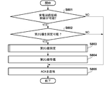
- the power receiving device 102 determines whether or not the power receiving device 102 can be controlled to form a closed circuit including the power receiving coil 201 and the resonance capacitor 207 for the measurement of the second Q value (S801).
- the process proceeds to S802, and when it is determined that the control for forming the closed circuit is not possible (NO in S801). The process proceeds to S805.
- the power receiving device 102 determines whether or not the own device can measure the second Q value of the power receiving circuit. Then, when the power receiving device 102 can measure the second Q value (YES in S802), the process proceeds to S803, and when the measurement of the second Q value is not possible (NO in S802), the process is changed to S805. Proceed.
- the power receiving device 102 measures the second Q value in S803, then transmits the Q value measured in S803 in S804 to the power transmission device 100, and proceeds to the process in S805. Then, in S805, the power receiving device 102 receives the result of foreign matter detection from the power transmission device 100 and ends the process.
- the power receiving device 102 determines in S801 that the power receiving device 102 can control to form a closed circuit including the power receiving coil 201 and the resonance capacitor 207 for the measurement of the second Q value. Further, the power receiving device 102 determines in S802 that the own device can measure the second Q value of the power receiving circuit. Then, the power receiving device 102 executes the processes from S803 to S805, and ends the process of FIG.
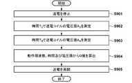
- the power transmission device 100 stops power transmission within 50 ms, which is the value negotiated in the negotiation of the measurement start time, after the transmission of the ACK is completed by, for example, F626 (the transmission of the rear end in the time domain of the ACK is completed). (S901).
- the power transmission device 100 measures the voltage value A 3 of the power transmission coil at time T 3 (S902), also measures the voltage value A 4 of the power transmission coil at time T 4 (S903).
- the power transmission device 100 calculates the Q value from the operating frequency, the measurement time, and the voltage value as described above (S904). Then, the power transmission device 100 resumes power transmission (S905) after a lapse of 100 ms or more, which is a value negotiated in the negotiation of the window length, from the stop of power transmission in S901, and ends the process.
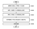
- the power receiving device 102 detects that the power transmission is stopped within 50 ms, which is the value negotiated in the negotiation of the measurement start time, after the reception of the ACK is completed by F626 (the rear end in the time domain of the ACK is received). do. Then, the power receiving device 102 executes control for forming a closed circuit including the power receiving coil 201 and the resonance capacitor 207 (S1001).
- the power receiving device 102 measures the voltage value A 3 of the power receiving coil at time T 3 (S1002), and measures the voltage value A 4 of the power receiving coil at time T 4 (S1003). Then, the power receiving device 102 calculates the Q value from the operating frequency, the measurement time, and the voltage value (S1004). After that, the power receiving device 102 reconnects the load (S1005) before 100 ms, which is the value negotiated in the window length negotiation, elapses from the stop of power transmission detected in S1001, and ends the process. The load is reconnected by turning off the switch 208.
- FIGS. 7 to 10 can be realized, for example, by the control unit 300 of the power transmission device 100 or the control unit 200 of the power receiving device 102 reading and executing a program stored in advance.
- the present invention is not limited to this, and at least a part of these processes may be realized by hardware.
- a dedicated circuit can be automatically generated on the FPGA from the program for realizing each processing step.
- FPGA is an acronym for Field Programmable Gate Array.
- a Gate Array circuit may be formed so that hardware that executes at least a part of the above-mentioned processing can be realized.
- the power receiving device 102 can recognize the timing when the power transmission device 100 stops the power transmission, and can appropriately start the measurement of the second Q value. ..
- the measurement of the second Q value is started at a timing suitable for the power receiving device 102. You will be able to. For example, when it is necessary to transmit another packet near the time when the power receiving device 102 measures the 2Q value, the measurement start time is negotiated so that the 2Q value measurement can be completed before the packet transmission starts. sell.
- the power transmission device 100 can stop the power transmission at the timing when the power receiving device 102 completes the configuration of the closed circuit and the like and can start the measurement process of the second Q value.
- the power receiving device 102 can reconnect the power receiving coil 201 to the load at an appropriate timing. That is, if power transmission is restarted in the power receiving device 102 while the closed circuit is configured, an excessive current may flow through the power receiving coil 201 and the resonance capacitor 207.
- the window length is determined in advance by negotiation, it is possible to prevent such a situation from occurring.
- the time required for measuring the second Q value may differ depending on the performance of the power receiving device 102 and the required measurement accuracy.
- the power receiving device 102 of the present embodiment secures a sufficient measurement period by negotiating the window length according to the performance of the own device and the required measurement accuracy, and causes a measurement failure or measurement. It is possible to prevent a decrease in accuracy.
- the measurement start timing, the measurement period length, and the period (time-out time) until the measurement report of the 2Q value in the power receiving device are all determined by negotiation. At least one of the above may be negotiated. That is, for example, only one of these negotiations may be carried out, or only two of these negotiations may be carried out. That is, these elements may be used independently of each other, and not all of them must always be used.
- the present invention supplies a program that realizes one or more functions of the above-described embodiment to a system or device via a network or storage medium, and one or more processors in the computer of the system or device reads and executes the program. It can also be realized by the processing to be performed. It can also be realized by a circuit (for example, ASIC) that realizes one or more functions.
- a circuit for example, ASIC
Landscapes
- Engineering & Computer Science (AREA)
- Power Engineering (AREA)
- Computer Networks & Wireless Communication (AREA)
- Physics & Mathematics (AREA)
- General Physics & Mathematics (AREA)
- General Engineering & Computer Science (AREA)
- Charge And Discharge Circuits For Batteries Or The Like (AREA)
Abstract
送電コイルを介して受電装置に無線で電力を送ることができると共にその受電装置と通信することができる送電装置は、送電装置から受電装置へ送電を行うフェーズにおいて、測定した送電コイルのQ値に基づいて、受電装置とは異なる物体の有無を判定する。送電装置は、通信によって受電装置から受信した、送電コイルのQ値の測定に基づく受電装置とは異なる物体の有無の判定に関する所定の処理を受電装置が実行可能か否かを示す情報に基づいて、送電コイルのQ値の測定に基づく受電装置とは異なる物体の有無の判定を実行するか否かを制御する。
Description
本発明は、送電装置、受電装置、制御方法、およびプログラムに関し、特に、無線電力伝送における異物検出技術に関するものである。
無線電力伝送システムの技術開発が広く行われており、標準化団体Wireless Power Consortium(WPC)が無線充電規格として策定した規格(WPC規格)が広く知られている。このような無線電力伝送では、送電装置が電力を伝送可能な範囲に異物が存在する場合に、その異物を検出して送受電を制御することが肝要になる。異物とは、受電装置とは異なる物体である。特許文献1では、WPC規格に準拠した送受電装置の近傍に異物が存在する場合に、その異物を検出して送受電を制限する手法が記載されている。特許文献2には、無線電力伝送システムのコイルを短絡させて異物検出を行う技術が開示されている。また、特許文献3には、無線電力伝送システムの送電コイルに一定期間高周波信号を印加して測定したそのコイルのQ値(Quality factor)の変化によって異物を検出する技術が記載されている。
本発明は、WPC規格に準拠した送電装置および受電装置において、受電装置とは異なる物体の検出をより高精度に実行可能とする技術を提供する。
本発明の一態様による送電装置は、送電コイルを介して受電装置に無線で電力を送る送電手段と、前記受電装置と通信する通信手段と、前記送電装置から前記受電装置へ送電を行うフェーズにおいて、前記送電コイルのQ値を測定する測定手段と、前記送電コイルのQ値に基づいて、前記受電装置とは異なる物体の有無を判定する判定手段と、前記通信手段によって前記受電装置から受信した、前記送電コイルのQ値の測定に基づく前記受電装置とは異なる物体の有無の判定に関連する所定の処理を前記受電装置が実行可能か否かを示す情報に基づいて、前記送電コイルのQ値の測定に基づく前記受電装置とは異なる物体の有無の判定を実行するか否かを制御する制御手段と、を有する。
本発明によれば、WPC規格に準拠した送電装置および受電装置において、受電装置とは異なる物体の検出をより高精度に実行することができる。
本発明のその他の特徴及び利点は、添付図面を参照とした以下の説明により明らかになるであろう。なお、添付図面においては、同じ若しくは同様の構成には、同じ参照番号を付す。
添付図面は明細書に含まれ、その一部を構成し、本発明の実施の形態を示し、その記述と共に本発明の原理を説明するために用いられる。
図1は、無線電力伝送システムの構成例を示す図である。
図2は、受電装置の構成例を示す図である。
図3は、送電装置の構成例を示す図である。
図4は、送電装置の制御部の機能構成例を示す図である。
図5は、受電装置の制御部の機能構成例を示す図である。
図6Aは、従来の送電装置と受電装置とが実行する処理の流れの例を示す図である。
図6Bは、実施形態に係る送電装置と受電装置とが実行する処理の流れの例を示す図である。
図7は、送電装置による第3異物検出処理の流れの例を示す図である。
図8は、受電装置による第3異物検出処理の流れの例を示す図である。
図9は、送電装置による第2Q値の測定処理の流れの例を示す図である。
図10は、受電装置による第2Q値の測定処理の流れの例を示す図である。
図11は、パワーロス手法による異物検出を説明する図である。
図12Aは、時間領域におけるQ値測定方法を説明する図である。
図12Bは、時間領域におけるQ値測定方法を説明する図である。
図13は、Configuration Packetのフレームフォーマットを示す図である。
以下、添付図面を参照して実施形態を詳しく説明する。なお、以下の実施形態は特許請求の範囲に係る発明を限定するものではない。実施形態には複数の特徴が記載されているが、これらの複数の特徴の全てが発明に必須のものとは限らず、また、複数の特徴は任意に組み合わせられてもよい。さらに、添付図面においては、同一若しくは同様の構成に同一の参照番号を付し、重複した説明は省略する。
(システム構成)
図1に、本実施形態に係る無線電力伝送システムの構成例を示す。本無線電力伝送システムは、一例において、送電装置100と受電装置102とを含んで構成される。送電装置100と受電装置102は、WPC(Wireless Power Consortium)規格に準拠しているものとする。送電装置100は、例えば自装置上に載置された受電装置102に対して無線で送電する電子機器である。送電装置100は、送電コイル101を介して受電装置102へ無線で電力を送る。受電装置102は、例えば、送電装置100から受電して内蔵バッテリに充電を行う電子機器である。また、受電装置102は、他の装置(カメラ、スマートフォン、タブレットPC、ラップトップ、自動車、ロボット、医療機器、プリンター)に内蔵され、それらの装置に電力を供給するように構成されてもよい。送電装置100がスマートフォンなどであってもよい。この場合、例えば受電装置102は、別のスマートフォンであってもよいし、無線イヤホンであってもよい。また、受電装置102は、自動車等の車両や輸送機であってもよいし、送電装置100は自動車等の車両や輸送機のコンソール等に設置される充電器であってもよい。
図1に、本実施形態に係る無線電力伝送システムの構成例を示す。本無線電力伝送システムは、一例において、送電装置100と受電装置102とを含んで構成される。送電装置100と受電装置102は、WPC(Wireless Power Consortium)規格に準拠しているものとする。送電装置100は、例えば自装置上に載置された受電装置102に対して無線で送電する電子機器である。送電装置100は、送電コイル101を介して受電装置102へ無線で電力を送る。受電装置102は、例えば、送電装置100から受電して内蔵バッテリに充電を行う電子機器である。また、受電装置102は、他の装置(カメラ、スマートフォン、タブレットPC、ラップトップ、自動車、ロボット、医療機器、プリンター)に内蔵され、それらの装置に電力を供給するように構成されてもよい。送電装置100がスマートフォンなどであってもよい。この場合、例えば受電装置102は、別のスマートフォンであってもよいし、無線イヤホンであってもよい。また、受電装置102は、自動車等の車両や輸送機であってもよいし、送電装置100は自動車等の車両や輸送機のコンソール等に設置される充電器であってもよい。
また、図1は、導電性の異物103が、送電コイル101から出力される無線電力が影響を及ぼす範囲(operating volume)に存在している状況を例示している。このような異物103がoperating volume内に存在すると、送受電の効率が劣化し、場合によっては発熱等の問題が生じうる。このため、送電装置100と受電装置102は、このような異物103を検出して、送受電制御を実行することが重要となる。そこで、本実施形態では、送電装置100および受電装置102が、WPC規格に準拠する制御の範囲内で、送電コイル内部の電圧の時間変化からQ値(Quality factor)を測定して、このような異物103を検出して、送受電の制御を行う。以下では、このような手順を実行する装置の構成と処理の流れの例について詳細に説明する。なお、異物103は、受電装置とは異なる物体である。異物103としては、例えば、金属片やICカードのような導電性の物体である。
(装置の構成)
図2に、受電装置102の構成例を示す。受電装置102は、例えば、制御部200、受電コイル201、整流部202、電圧制御部203、通信部204、充電部205、バッテリ206、共振コンデンサ207、および、スイッチ208を含んで構成される。制御部200は、受電装置102の全体を制御する。制御部200は、例えばCPU(Central Processing Unit)やMPU(Micro Processing Unit)等の1つ以上のプロセッサを含んで構成される。なお、制御部200は、例えば、RAM(Random Access Memory)やROM(Read Only Memory)等の1つ以上の記憶装置を含んでもよい。そして、制御部200は、例えば、記憶装置に記憶されたプログラムをプロセッサによって実行することにより、後述の各処理を実行するように構成されうる。受電コイル201は、送電装置100の送電コイル101から電力を受電する際に用いられるコイルである。整流部202は、受電コイル201を介して受電した交流電圧および交流電流を、直流電圧および直流電流に変換する。電圧制御部203は、整流部202から入力された直流電圧のレベルを、制御部200および充電部205などが動作するのに適した(過大でもなく過少でもない)直流電圧のレベルに変換する。また、電圧制御部203は、変換されたレベルの電圧を充電部205へ供給する。充電部205は、電圧制御部203から供給された電圧によりバッテリ206を充電する。通信部204は、送電装置100との間で、WPC規格に基づいた無線充電の制御通信を行う。この制御通信は、受電コイル201で受電した交流電圧および交流電流を負荷変調することにより行われる。
図2に、受電装置102の構成例を示す。受電装置102は、例えば、制御部200、受電コイル201、整流部202、電圧制御部203、通信部204、充電部205、バッテリ206、共振コンデンサ207、および、スイッチ208を含んで構成される。制御部200は、受電装置102の全体を制御する。制御部200は、例えばCPU(Central Processing Unit)やMPU(Micro Processing Unit)等の1つ以上のプロセッサを含んで構成される。なお、制御部200は、例えば、RAM(Random Access Memory)やROM(Read Only Memory)等の1つ以上の記憶装置を含んでもよい。そして、制御部200は、例えば、記憶装置に記憶されたプログラムをプロセッサによって実行することにより、後述の各処理を実行するように構成されうる。受電コイル201は、送電装置100の送電コイル101から電力を受電する際に用いられるコイルである。整流部202は、受電コイル201を介して受電した交流電圧および交流電流を、直流電圧および直流電流に変換する。電圧制御部203は、整流部202から入力された直流電圧のレベルを、制御部200および充電部205などが動作するのに適した(過大でもなく過少でもない)直流電圧のレベルに変換する。また、電圧制御部203は、変換されたレベルの電圧を充電部205へ供給する。充電部205は、電圧制御部203から供給された電圧によりバッテリ206を充電する。通信部204は、送電装置100との間で、WPC規格に基づいた無線充電の制御通信を行う。この制御通信は、受電コイル201で受電した交流電圧および交流電流を負荷変調することにより行われる。
また、受電コイル201は、共振コンデンサ207と接続され、特定の周波数F2で共振するように構成される。スイッチ208は、受電コイル201と共振コンデンサ207を短絡するためのスイッチであり、制御部200によって制御される。スイッチ208がオンとされると、受電コイル201と共振コンデンサ207が直列共振回路を構成する。このとき、受電コイル201と共振コンデンサ207およびスイッチ208の閉回路にのみ電流が流れ、整流部202や電圧制御部203には電流が流れなくなる。これに対して、スイッチ208がオフとされると、受電コイル201および共振コンデンサ207を介して、整流部202および電圧制御部203に電流が流れるようになる。
図3に、送電装置100の構成例を示す、送電装置100は、例えば、制御部300、電源部301、送電部302、送電コイル303、通信部304、メモリ305、共振コンデンサ306、およびスイッチ307を含んで構成される。制御部300は、送電装置100の全体を制御する。制御部300は、例えばCPUやMPU等の1つ以上のプロセッサを含んで構成される。なお、制御部300は、例えば、後述のメモリ305や制御部300に内蔵された記憶装置に記憶されたプログラムをプロセッサによって実行することにより、後述の各処理を実行するように構成されうる。電源部301は、各機能ブロックに電源を供給する。電源部301は、例えば、商用電源又はバッテリである。バッテリには、例えば、商用電源から供給される電力が蓄電されうる。
送電部302は、電源部301から入力された直流又は交流電力を、無線電力伝送に用いる周波数帯の交流電力に変換し、その交流電力を送電コイル303へ入力し、これにより受電装置102に受電させるための電磁波を送電コイル303から発生させる。例えば、送電部302は、電源部301により供給される直流電圧を、FET(Field Effect Transister)を使用したハーフブリッジ又はフルブリッジ構成のスイッチング回路で交流電圧に変換する。この場合、送電部302は、FETのON/OFFを制御するゲ-トドライバを含む。また、送電部302は、送電コイル303に入力する電圧(送電電圧)と電流(送電電流)との少なくともいずれか、または、周波数を調節することにより、出力させる電磁波の強度や周波数を制御する。例えば、送電部302は、送電電圧又は送電電流を大きくすることにより電磁波の強度を強くし、送電電圧又は送電電流を小さくすることにより電磁波の強度を弱くする。ここで、送電部302は、WPC規格に対応した受電装置102の充電部205に対して15ワット(W)の電力を出力するだけの電力を供給する能力があるものとする。また、送電部302は、制御部300の指示に基づいて、送電コイル303による電磁波の出力が開始又は停止されるように、交流電力の出力制御を行う。
通信部304は、送電コイル303を介して、受電装置102との間で、WPC規格に基づく送電制御のための通信を行う。通信部304は、送電部302から出力される交流電圧および交流電流を周波数変調(FSK(Frequency Shift Keying))を用いて変調し、受電装置102へ情報を伝送する。また、通信部304は、受電装置102の通信部204による負荷変調で変調された交流電圧および交流電流を復調して、受電装置102が送信した情報を取得する。すなわち、通信部304は、送電部302から送電される電磁波に受電装置102へ送信すべき情報を重畳し、その電磁波に対して受電装置102によって重畳された受信信号を検出することによって、受電装置102と通信する。また、通信部304は、送電コイル303とは異なるコイル(又はアンテナ)を用いて、WPC規格とは異なる規格に従って受電装置102と通信を行ってもよい。また、通信部304は、複数の通信機能を選択的に用いて受電装置102と通信してもよい。メモリ305は、例えば、制御部300によって実行される制御プログラムや、送電装置100及び受電装置102の状態などの情報を記憶する。例えば、送電装置100の状態は制御部300により取得される。また、受電装置102の状態は、受電装置102の制御部200により取得されて通信部205から送信され、送電装置100は、通信部304を介してこの状態を示す情報を取得する。
また、送電コイル303は、共振コンデンサ306と接続され、特定の周波数F1で共振するように構成される。スイッチ307は、送電コイル303と共振コンデンサ306とを短絡するためのスイッチであり、制御部300によって制御される。スイッチ307がオンとされると、送電コイル303と共振コンデンサ306が直列共振回路を構成する。このとき、送電コイル303と共振コンデンサ306およびスイッチ307の閉回路にのみ電流が流れる。スイッチ208がオフとされると、送電コイル303および共振コンデンサ306には、送電部302から電力が供給される。
図4は、送電装置100の制御部300によって実現される機能構成例を示している。制御部300は、例えば、第1Q値測定部400、第2Q値測定部401、Calibration処理部402、第1異物検出処理部403、第2異物検出処理部404、第3異物検出処理部405、および送電処理部406の各機能部として動作しうる。第1Q値測定部400は、後述のようにして、周波数領域におけるQ値の測定(第1Q値測定)を行う。第2Q値測定部401は、後述のようにして、時間領域におけるQ値の測定(第2Q値測定)を行う。Calibration処理部402は、後述のようにして、Calibration data Pointの取得およびCalibrationカーブの作成処理を行う。第1異物検出処理部403は、第1Q値測定部400により測定された第1Q値に基づく異物検出処理(第1異物検出処理)を実行する。第2異物検出処理部404は、後述するパワーロス手法に基づく異物検出処理(第2異物検出処理)を実行する。第3異物検出処理部405は、第2Q値測定部401により測定された第2Q値に基づく異物検出処理(第3異物検出処理)を実行する。送電処理部406は、送電部302の送電開始、送電停止、送電電力の増減に関する処理を行う。図4に示される各処理部は、例えば、それぞれが独立した複数のプログラムとして構成され、イベント処理等により、これらの複数のプログラム間の同期をとりながら並行して動作しうる。
図5は、受電装置102の制御部200によって実現される機能構成例を示している。制御部200は、例えば、第2Q値測定部500と受電処理部501の各機能部として動作しうる。第2Q値測定部500は、後述のようにして、時間領域におけるQ値の測定(第2Q値測定)を行う。受電処理部501は、受電装置102の受電開始、受電停止、送電装置100に対して要求する電力の増減に関する処理を行う。図5に示す各処理部は、それぞれが独立したプログラムとして構成され、イベント処理等によりプログラム間の同期をとりながら並行して動作しうる。
(WPC規格における異物検出方法)
続いて、WPC(Wireless Power Consortium)規格で規定されている異物検出方法について、送電装置100と受電装置102を例として用いて説明する。ここでは、周波数領域で測定されたQ値に基づく異物検出方法(第1異物検出方法)と、パワーロス手法に基づく異物検出方法(第2異物検出方法)について説明する。
続いて、WPC(Wireless Power Consortium)規格で規定されている異物検出方法について、送電装置100と受電装置102を例として用いて説明する。ここでは、周波数領域で測定されたQ値に基づく異物検出方法(第1異物検出方法)と、パワーロス手法に基づく異物検出方法(第2異物検出方法)について説明する。
(1)周波数領域で測定されたQ値に基づく異物検出方法(第1異物検出方法)
第1異物検出方法では、まず、送電装置100が、異物の影響によって変化するQ値の周波数領域における測定(第1Q値測定)を行う。この測定は、送電装置100がAnalog Pingを送電してから、Digital Pingを送電するまでの間に実行される(図6AのF601を参照)。例えば、送電部302は、Q値を測定するために、送電コイル303が出力する無線電力の周波数を掃引し、第1Q値測定部400は送電コイルと直列(または並列)に接続される共振コンデンサ306の端部の電圧値を測定する。そして、第1Q値測定部400は、その電圧値がピークとなる共振周波数を探索し、共振周波数で測定されるピークの電圧値から3dB下がった電圧値を示す周波数と、その共振周波数とから、送電コイル303のQ値を算出する。
第1異物検出方法では、まず、送電装置100が、異物の影響によって変化するQ値の周波数領域における測定(第1Q値測定)を行う。この測定は、送電装置100がAnalog Pingを送電してから、Digital Pingを送電するまでの間に実行される(図6AのF601を参照)。例えば、送電部302は、Q値を測定するために、送電コイル303が出力する無線電力の周波数を掃引し、第1Q値測定部400は送電コイルと直列(または並列)に接続される共振コンデンサ306の端部の電圧値を測定する。そして、第1Q値測定部400は、その電圧値がピークとなる共振周波数を探索し、共振周波数で測定されるピークの電圧値から3dB下がった電圧値を示す周波数と、その共振周波数とから、送電コイル303のQ値を算出する。
また、別の方法でQ値を測定してもよい。例えば、送電部302は、送電コイル303が出力する無線電力の周波数を掃引し、第1Q値測定部400は送電コイル303と直列に接続される共振コンデンサ306の端部の電圧値を測定して、その電圧値がピークとなる共振周波数を探索する。そして、第1Q値測定部400は、その共振周波数においてその共振コンデンサ306の両端の電圧値を測定し、その両端の電圧値の比から送電コイル303のQ値を算出する。
送電コイル303のQ値を算出した後、送電装置100の第1異物検出処理部403は、通信部304を介して、異物検出の判断基準となるQ値を受電装置102から取得する。例えば、第1異物検出処理部403は、WPC規格で規定された送電コイル上に受電装置が置かれた場合の送電コイルのQ値(第1の特性値)を、受電装置102から受信する。このQ値は、受電装置102が送信するFOD(Foreign Object Detection) Statusパケットに格納されて、送電装置100は、このFOD Statusパケットを受信することによりこのQ値を取得する。第1異物検出処理部403は、取得したQ値から、送電装置100上に受電装置102が置かれた場合の、送電コイル303のQ値を推定する。本実施形態では、推定されたQ値を第1基準Q値と呼ぶ。なお、FOD Statusパケットに格納されるQ値は、あらかじめ受電装置102の不揮発メモリ(不図示)に記憶されうる。すなわち、受電装置102は、事前に記憶していたQ値を送電装置100へ通知しうる。なお、このQ値は、後述するQ1に対応する。
送電装置100の第1異物検出処理部403は、第1基準Q値と、第1Q値測定部400により測定されたQ値とを比較し、比較結果に基づいて異物の有無を判定する。例えば、第1異物検出処理部403は、第1基準Q値に対して、a%(第1の割合)低下したQ値を閾値として、測定されたQ値がその閾値より低い場合に、異物がある可能性が高いと判定し、そうでない場合は異物がない可能性が高いと判定する。
(2)パワーロス手法に基づく異物検出方法(第2異物検出方法)
続いて、WPC規格で規定されているパワーロス手法に基づく異物検出方法について、図11を参照して説明する。図11は、パワーロス手法による異物検出の概念図であり、横軸は送電装置100の送電電力を示し、縦軸は受電装置102の受電電力を示す。なお、送電装置100の送電部302による送電電力の制御は、送電処理部406により行われうる。
続いて、WPC規格で規定されているパワーロス手法に基づく異物検出方法について、図11を参照して説明する。図11は、パワーロス手法による異物検出の概念図であり、横軸は送電装置100の送電電力を示し、縦軸は受電装置102の受電電力を示す。なお、送電装置100の送電部302による送電電力の制御は、送電処理部406により行われうる。
まず、送電装置100の送電部302は、受電装置102に対してDigital Pingを送電する。そして、送電装置100の通信部304は、受電装置102における受電電力値Pr1(Light Loadという)を、Received Power Packet(mode1)により受信する。なお、以下では、Received Power Packet(mode1)を「RP1」と呼ぶ。Pr1は、受電装置102が受電電力を負荷(充電部205とバッテリ206など)に供給していない場合の受電電力値である。送電装置100の制御部300は、受信したPr1と、Pr1が得られたときの送電電力値Pt1との関係(図11の点1100)を、メモリ305に記憶する。これにより、送電装置100は、送電電力としてPt1を送電したときの、送電装置100と受電装置102との間の電力損失量がPt1-Pr1(Ploss1)であることを認識することができる。
次に、送電装置100の通信部304は、受電装置102における受電電力値Pr2(Connected Loadという)の値を、Received Power Packet(mode2)で受電装置102から受信する。なお、以下では、Received Power Packet(mode2)を「RP2」と呼ぶ。Pr2は、受電装置102が受電電力を負荷に供給している場合の受電電力値である。そして送電装置100の制御部300は、受信したPr2と、Pr2が得られたときの送電電力値Pt2との関係(図11の点1101)を、メモリ305に記憶する。これにより、送電装置100は、送電電力としてPt2を送電したときの、送電装置100と受電装置102との間の電力損失量がPt2-Pr2(Ploss2)であることを認識することができる。
そして送電装置100のCalibration処理部402は、点1100と点1101とを直線補間し、直線1102を作成する。直線1102は、送電装置100と受電装置102の周辺に異物が存在しない状態における、送電電力と受電電力の関係に対応する。このため、送電装置100は、送電電力値と直線1102とから、異物がない可能性が高い状態における受電電力を予想することができる。例えば、送電装置100は、送電電力値がPt3の場合について、送電電力値がPt3である場合に対応する直線1102上の点1103から、受電電力値がPr3であると予想することができる。
ここで、送電装置100の送電部302が、Pt3の送電電力で受電装置102に対して送電した場合に、通信部304が受電装置102から受電電力値Pr3’という値を受信したとする。送電装置100の第2異物検出処理部404は、異物が存在しない状態における受電電力値Pr3から、実際に受電装置102から受信した受電電力値Pr3’を引いた値Pr3-Pr3’(=Ploss_FO)を算出する。このPloss_FOは、送電装置100と受電装置102との間に異物が存在する場合に、その異物で消費される電力損失と考えることができる。このため、第2異物検出処理部404は、異物で消費されたであろう電力Ploss_FOがあらかじめ決められた閾値を超えた場合に、異物が存在すると判断することができる。この閾値は、例えば、点1100と点1101との関係に基づいて導出される。
また、送電装置100の第2異物検出処理部404は、事前に、異物が存在しない状態における受電電力値Pr3から、送電装置100と受電装置102間の電力損失量Pt3-Pr3(Ploss3)を求めておく。そして、第2異物検出処理部404は、異物が存在するか不明な状態において受電装置102から受信した受電電力値Pr3’から、異物が存在する状態での送電装置100と受電装置102間の電力損失量Pt3-Pr3’(Ploss3’)を算出する。そして、第2異物検出処理部404は、Ploss3’-Ploss3を算出し、この値があらかじめ決められた閾値を超えた場合に、異物が存在すると判断することができる。なお、Ploss3’-Ploss3=Pt3-Pr3’-Pt3+Pr3=Pr3-Pr3’である。このため、電力損失量の比較により、異物で消費されたと予測される電力Ploss_FOを推定することもできる。
以上のように、異物で消費されたであろう電力Ploss_FOは、受電電力の差Pr3-Pr3’として算出されてもよいし、電力損失の差Ploss3’-Ploss3(=Ploss_FO)として算出されてもよい。
Calibration処理部402により直線1102が取得されたのち、送電装置100の第2異物検出処理部404は、通信部304を介して、受電装置102から定期的に現在の受電電力値(例えば上記のPr3’)を受信する。受電装置102が定期的に送信する現在の受電電力値は、Received Power Packet(mode0)として送電装置100に送信される。送電装置100の第2異物検出処理部404は、Received Power Packet(mode0)に格納されている受電電力値と、直線1102とに基づいて異物検出を行う。なお、以下では、Received Power Packet(mode0)を「RP0」と呼ぶ。
なお、送電装置100と受電装置102の周辺に異物が存在しない状態における送電電力と受電電力の関係である直線1102を取得するための点1100および点1101を、本実施形態では「Calibration data Point」と呼ぶ。また、少なくとも2つのCalibration data Pointを補間して取得される線分(直線1102)を「Calibrationカーブ」と呼ぶ。Calibration data PointおよびCalibrationカーブ(第2の基準)は、第2異物検出処理部404による異物検出処理のために使用される。
(時間領域におけるQ値測定方法)
時間領域におけるQ値の測定方法について、図12A及び図12Bを用いて説明する。図12A及び図12Bは、時間領域におけるQ値の測定(第2Q値測定)の方法を説明するための概念図である。本実施形態では、第2Q値に基づく異物検出方法を第3異物検出方法と呼ぶ。第2Q値測定は、第2Q値測定部401により行われる。また、送電装置100の送電部302による送電電力の制御は、送電処理部406により行われる。第2Q値測定では、送電装置100と受電装置102が、同じ期間にスイッチをオンとして、送電を瞬断させたうえで、受電電力を負荷に届けないようにする。これによれば、例えばコイルに印加される電圧が徐々に減少する。そして、この減少の仕方によって第2Q値が算出される。
時間領域におけるQ値の測定方法について、図12A及び図12Bを用いて説明する。図12A及び図12Bは、時間領域におけるQ値の測定(第2Q値測定)の方法を説明するための概念図である。本実施形態では、第2Q値に基づく異物検出方法を第3異物検出方法と呼ぶ。第2Q値測定は、第2Q値測定部401により行われる。また、送電装置100の送電部302による送電電力の制御は、送電処理部406により行われる。第2Q値測定では、送電装置100と受電装置102が、同じ期間にスイッチをオンとして、送電を瞬断させたうえで、受電電力を負荷に届けないようにする。これによれば、例えばコイルに印加される電圧が徐々に減少する。そして、この減少の仕方によって第2Q値が算出される。
図12Aにおける波形1200は、送電装置100の送電コイル303又は共振コンデンサ306の端部に印加される高周波電圧の値(以下では、単に「送電コイルの電圧値」と呼ぶ。)の時間経過を示している。なお、図12A及び図12Bにおいて、横軸は時間を示しており、縦軸は電圧値を示している。時間T0において高周波電圧の印加(送電)が停止される。点1201は、高周波電圧の包絡線上の一点であり、時間T1における高周波電圧である。図12Aにおける(T1、A1)は、時間T1における電圧値がA1であることを示す。同様に、点1202は、高周波電圧の包絡線上の一点であり、時間T2における高周波電圧である。図12Aにおける(T2、A2)は、時間T2における電圧値がA2であることを示す。
Q値測定は、時間T0以降の電圧値の時間変化に基づいて実行される。例えば、Q値は、電圧値の包絡線である点1201および点1202の時間、電圧値、および、高周波電圧の角速度ω(ω=2πf、fは高周波電圧の動作周波数)に基づいて、(式1)により算出される。
 (式1)
(式1)
次に、本実施形態で送電装置100が時間領域でQ値を測定するための処理について図12Bを参照して説明する。波形1203は、送電コイル303に印加される高周波電圧の値を示しており、その周波数は、Qi規格で使用される110kHzから148.5kHzの間の周波数である。また、点1204および点1205は、電圧値の包絡線の一部である。送電装置100の送電部302は、時間T0からT5の区間、送電を停止する。送電装置100の第2Q値測定部401は、時間T3における電圧値A3(点1204)、時間T4における電圧値A4(点1205)および高周波電圧の動作周波数と(式1)に基づいて、Q値を測定する。なお、送電装置100の送電部302は、時間T5において送電を再開する。このように、第2Q値測定は、送電装置100が送電を瞬断し時間経過と電圧値および動作周波数に基づいてQ値を測定することにより行われる。
なお、第3異物検出方法において、(T3、A3)、(T4、A4)を測定すればよく、第2Q値を測定しなくてもよい。すなわち、(式1)で示すように、T4-T3の値と、A3に対するA4の比率(A4/A3)またはA3のA4に対する比率(A3/A4)の値に基づく指標を用いることで、異物の有無を検出するようにしてもよい。具体的には、その指標と閾値とを比較することにより、異物の有無を検出すればよい。
また、第3異物検出方法において、電圧値の代わりに電流値を測定し、その電流値の比に基づく指標を用いて、異物の有無を検出してもよい。すなわち、T3における電流値、及び、時間T4における電流値を測定すればよい。また、電流値に基づいて第2Q値を取得してもよい。
(従来の送電装置および受電装置の動作)
従来の送電装置100と受電装置102の動作について図6Aを用いて説明する。図6Aの説明では、送電装置100と受電装置102は、それぞれ、WPC規格v1.2.3に準拠した送電装置および受電装置であるとする。
従来の送電装置100と受電装置102の動作について図6Aを用いて説明する。図6Aの説明では、送電装置100と受電装置102は、それぞれ、WPC規格v1.2.3に準拠した送電装置および受電装置であるとする。
送電装置100は、送電コイル303の近傍に存在する物体を検出する為にAnalog Pingを送電する(F600)。Analog Pingは、パルス状の電力で、物体を検出するための電力である。また、Analog Pingは、受電装置102がこれを受電したとしても、制御部200を起動することができない程度の微小な電力である。送電装置100は、Analog Pingにより、送電コイル303の近傍に存在する物体に起因する送電コイル303内部の電圧値の共振周波数のシフトや、送電コイル303を流れる電圧値・電流値の変化によって物体を検出する。送電装置100は、Analog Pingにより物体を検出すると、上述の第1Q値測定により送電コイル303のQ値を測定する(F601)。そして、送電装置100は、第1Q値測定に続いて、Digital Pingの送電を開始する(F602)。Digital Pingは、受電装置102の制御部200を起動させるための電力であり、Analog Pingよりも大きい電力である。また、Digital Pingは、以降、連続的に送電される。すなわち、送電装置100は、Digital Pingの送電を開始してから(F602)、受電装置102から後述のEPT(End Power Transfer)パケットの受信(F622)まで、Digital Ping以上の電力を送電し続ける。
受電装置102は、Digital Pingを受電して起動すると、受電したDigital Pingの電圧値をSignal Strengthパケットに格納して送電装置100へ送信する(F603)。続いて、受電装置102は、受電装置102が準拠しているWPC規格のバージョン情報やデバイス識別情報を含むIDを格納したIDパケットを送電装置100へ送信する(F604)。さらに、受電装置102は、電圧制御部203が負荷(充電部205)へ供給する電力の最大値等の情報を含んだConfigurationパケットを送電装置100へ送信する(F605)。送電装置100は、IDパケットおよびConfigurationパケットを受信する。そして、送電装置100は、これらのパケットによって受電装置102がWPC規格v1.2以降の(後述のNegotiationを含む)拡張プロトコルに対応していると判定すると、ACKで応答する(F606)。
受電装置102は、ACKを受信すると、送受電する電力の交渉などを行うNegotiationフェーズに遷移する。まず、受電装置102は、送電装置100に対してFOD Statusパケットを送信する(F607)。本実施形態では、このFOD Statusパケットを「FOD(Q1)」と呼ぶ。送電装置100は、受信したFOD(Q1)に格納されているQ値(周波数領域で測定されたQ値)と第1Q値測定で測定したQ値とに基づいて、第1異物検出方法により異物検出を行う。そして、送電装置100は、異物がない可能性が高いと判定した場合に、その判定結果を示すACKを受電装置102に送信する(F608)。
受電装置102は、ACKを受信すると、受電装置102が受電を要求する電力値の最大値であるGuaranteed Power(GP)の交渉を行う。Guaranteed Powerは、送電装置100との間で合意された、受電装置102の負荷電力(バッテリ206が消費する電力)を示す。この交渉は、WPC規格で規定されているSpecific Requestのうち、受電装置102が、要求するGuaranteed Powerの値を格納したパケットを送電装置100へ送信することにより実現される(F609)。本実施形態では、このパケットを「SRQ(GP)」と呼ぶ。送電装置100は、自装置の送電能力等を考慮して、SRQ(GP)に応答する。送電装置100は、Guaranteed Powerを受け入れ可能であると判断した場合、その要求を受入れたことを示すACKを送信する(F610)。本実施形態では、受電装置102が、SRQ(GP)により、Guaranteed Powerとして15ワットを要求したものとする。受電装置102は、Guaranteed Powerを含む複数のパラメータの交渉が終了すると、Specific Requestのうち、交渉の終了(End Negotiation)を要求する「SRQ(EN)」を送電装置に送信する(F611)。そして、送電装置100は、SRQ(EN)に対してACKを送信し(F612)、Negotiationを終了して、Guaranteed Powerで定められた電力の送受電を行うPower Transferフェーズに遷移する。
続いて、送電装置100は、上述したパワーロス手法に基づく異物検出(第2異物検出方法)を実行する。まず、送電装置100は、RP1を受電装置102から受信する(F613)。送電装置100は、RP1に格納されている受電電力値と、その受電電力が得られたときの送電装置100の送電電力値を、Calibration data Point(図11の点1100に対応)として受け入れる。そして、送電装置100は、Calibration data Pointの受け入れを示すACKを、受電装置102へ送信する(F614)。
受電装置102は、ACKを受信後、送電装置100に対して受電電圧(または受電電流、受電電力)の増減を要求するControl Error(以後、CEと表現する)を送電装置100に送信する。CEには、符号および数値が格納され、符号がプラスであれば、電力を上げることを要求することを、マイナスであれば電力を下げることを要求することを、数値がゼロであれば電力の維持を要求することを、それぞれ意味する。ここでは、受電装置102は、電力を上げることを示すCE(+)を、送電装置100に送信する(F615)。
送電装置100は、CE(+)を受信すると、送電部302の設定値を変更して、送電電力を上げる(F616)。受電装置102は、CE(+)に応答して受電電力が上昇すると、受電した電力を負荷(充電部205やバッテリ206)に供給し、RP2を送電装置100に送信する(F617)。送電装置100は、RP2に格納されている受電電力値とその時の送電装置100の送電電力値を、Calibration data Point(図11の点1101に対応)として受け入れる。そして、送電装置100は、Calibration data Pointの受け入れを示すACKを、受電装置102へ送信する(F618)。この時点で、送電装置100は、2つのCalibration data Point(図11の点1100と点1101)を取得しているため、Calibrationカーブ(図11の直線1102)を導出することができる。
送電装置100および受電装置102は、この時点でPower Transferフェーズに遷移しており、送電装置100は、受電装置102がNegotiationフェーズで交渉した最大15ワットを受電可能な電力を送電している。受電装置102は、送電装置100に対して、送電電力の維持を要求するCEおよび現在の受電電力値を格納したRP0を送電装置100に定期的に送信する(F619、F620)。送電装置100は、受電装置102からRP0を受信すると、上述の第2異物検出方法に基づいて、異物検出を行う。送電装置100は、異物検出の結果、異物がない可能性が高いと判定した場合、ACKを受電装置102に送信する(F621)。その後、受電装置102は、バッテリ206への充電が終了すると、送電装置100に対して送電を停止することを要求するEPT(End Power Transfer)パケットを送信する(F622)。
以上のようにして、WPC規格v1.2.3に準拠した送電装置100と受電装置102との間で無線電力伝送が行われる。
図6Aの処理例に示すように、Power Transferフェーズの間は、Power Loss法による異物検出が行われる。しかし、1つの異物検出方法のみでは、異物がないにも関わらず異物があると誤検出することや、反対に異物があるにも関わらず異物がないと判定されてしまう可能性が一定程度残ってしまう。これに対して、複数の異物検出方法を組み合わせて実行すれば、異物検出の精度向上が期待できる。特に、Power Transferフェーズは、TXが送電を行うフェーズであり、送電中に、TXとRXの間に異物があると、異物からの発熱等が大きくなる。なお、異物はTXとRXの間になくても、送電可能範囲に存在することで、電力を受けて発熱してしまう。このため、このフェーズにおいて複数の異物検出を実行して、異物検出精度を向上させるメリットは大きい。そこで、本実施形態では、Power Transferフェーズにおいて、Power Loss法とは異なる異物検出方法を導入する。
ここで、周波数領域において測定されたQ値(第1Q値)に基づく異物検出(第1異物検出方法)は、測定のたびに共振周波数を探すために周波数を掃引する。送電装置100がDigital PingやPower Transferフェーズのなど比較的大きな電力を送電中にこのような掃引が実行されると、送電部302のスイッチングノイズの増大の原因となりうる。一方で、時間領域において測定されたQ値(第2Q値)に基づく異物検出(第3異物検出方法)は、単一の周波数で実行可能であり、周波数を掃引する必要がない。このため、Digital PingやPower Transferフェーズの送電時の動作周波数で実行可能であり、スイッチングノイズへの影響が少ない。本実施形態では、第2Q値測定において、送電装置が送電を停止した際に、スイッチ208をオンにし、受電コイル201と共振コンデンサ207を含む閉回路を構成する制御を行う。これにより、受電装置102における負荷の変動の影響を取り除いた状態で、第2Q値の測定を行う。
第3異物検出方法をWPC規格に適用する場合、受電装置102の装置構成は様々な態様が想定されるため、送電装置100が、受電装置102の能力に応じて行う処理を適切に制御する必要がある。例えば、送電装置100が閉回路を構成する制御ができない受電装置102に対して第2Q値測定を実行すると、その測定が、受電装置102の負荷の変動の影響を受けて、Q値を正しく測定することができない。また、第2Q値の測定は、受電装置102側において実行されることも想定されうるが、送電装置100は、受電装置102の能力がわからないと、自装置において第2Q値の測定を行うべきか否かを判定することができない。例えば、受電装置102が閉回路を構成可能であるが第2Q値の測定を実行することができない場合、送電装置100が第2Q値の測定を行わないと、異物の有無を判定することができない。同様に、受電装置102の能力がわからないと、送電装置100は、第2Q値の測定結果を受電装置102から受信する否かを判定することができない。例えば、受電装置102が第2Q値の測定を実行できないにも関わらず送電装置100が受電装置102から測定結果を受信しようとすると、不要な待機時間が発生してしまう。一方で、受電装置102が第2Q値の測定ができるにも関わらず、送電装置100が測定結果を受電装置102から受信しないと、送電装置100と受電装置102の間に状態ずれが発生してしまう。このため、本実施形態では、第2Q値の測定に基づく第3異物検出方法を適切にWPC規格に適用するための制御手法を使用する。以下では、この制御手法について説明する。
(第3異物検出方法をWPC規格に適用した場合の動作説明)
図6Bに本実施形態に係る送電装置100及び受電装置102によって実行される処理の流れの例を示す。なお、図6Aと同じ処理については同じ符号を付して説明を省略する。F600~F604の処理の実行後、受電装置102は、Configurationパケットを送電装置100に送信する(F623)。本実施形態では、このConfiguration Packetにおいて、受電装置102の能力情報が送電装置100へ通知される。通知される能力情報として、本実施形態では、Configuration Packet内に、Short Ability bitとMeasure Ability bitとを定義する。Short Ability bitは、受電装置102が第2Q値測定のために受電コイル201と共振コンデンサ207を含む閉回路を構成する制御が可能であるか否かを示す情報である。受電装置102は、例えば、自装置が第2Q値測定のために閉回路を構成する制御を行う能力を持っている場合はShort Ability bitに「1」を、そうでない場合は「0」を格納する。また、Measure Ability bitは、受電装置102が受電回路の第2Q値の測定を実行可能であるか否かを示す情報である。受電装置102は、例えば、自装置が受電回路の第2Q値の測定する能力を持っている場合はMeasure Ability bitに「1」を、そうでない場合は「0」を格納する。なお、これらの情報は、送電装置100によって実行される第2Q値の測定に基づく異物判定に関連付けられた所定の処理を、受電装置102が実行可能であるかを示す情報でありうる。すなわち、閉回路が構成可能であるか否かや、受電回路の第2Q値の測定を実行可能であるかは、この所定の処理の一類型に過ぎず、これら以外の処理についての情報ビットが受電装置102から送電装置100へ送信されてもよい。
図6Bに本実施形態に係る送電装置100及び受電装置102によって実行される処理の流れの例を示す。なお、図6Aと同じ処理については同じ符号を付して説明を省略する。F600~F604の処理の実行後、受電装置102は、Configurationパケットを送電装置100に送信する(F623)。本実施形態では、このConfiguration Packetにおいて、受電装置102の能力情報が送電装置100へ通知される。通知される能力情報として、本実施形態では、Configuration Packet内に、Short Ability bitとMeasure Ability bitとを定義する。Short Ability bitは、受電装置102が第2Q値測定のために受電コイル201と共振コンデンサ207を含む閉回路を構成する制御が可能であるか否かを示す情報である。受電装置102は、例えば、自装置が第2Q値測定のために閉回路を構成する制御を行う能力を持っている場合はShort Ability bitに「1」を、そうでない場合は「0」を格納する。また、Measure Ability bitは、受電装置102が受電回路の第2Q値の測定を実行可能であるか否かを示す情報である。受電装置102は、例えば、自装置が受電回路の第2Q値の測定する能力を持っている場合はMeasure Ability bitに「1」を、そうでない場合は「0」を格納する。なお、これらの情報は、送電装置100によって実行される第2Q値の測定に基づく異物判定に関連付けられた所定の処理を、受電装置102が実行可能であるかを示す情報でありうる。すなわち、閉回路が構成可能であるか否かや、受電回路の第2Q値の測定を実行可能であるかは、この所定の処理の一類型に過ぎず、これら以外の処理についての情報ビットが受電装置102から送電装置100へ送信されてもよい。
図13に、WPC規格v1.2.3のConfiguration Packetの構成を示す。なお、ここでは、本実施形態と関連しない部分の説明については省略する。WPC規格v1.2.3のConfiguration Packetは、複数のReserved領域を含んでいる。すなわち、Bank1のbit0からbit7の領域1300、Bank2のbit4からbit6の領域1301、Bank4のbit0からbit2の領域1302が、それぞれReserved領域である。本実施形態では、一例として、Short Ability bitをBank4のbit2に配置し、Measure Ability bitをBank4のbit1に配置する。なお、他のReserved領域にこれらのビットが配置されてもよい。また、これらのビットに代えて、WPC規格のバージョンを示す情報などがReserved領域に配置されてもよい。この場合、バージョンによって、受電装置102が第2Q値測定のために受電コイル201と共振コンデンサ207を含む閉回路を構成する制御が可能であるか否か、及び、受電装置102が受電回路の第2Q値の測定を実行可能であるか否か、が示されうる。例えば、将来のWPC規格のバージョンにおいて、そのバージョン準拠の受電装置102がこれらの機能を有することが必須であると規定されうる。この場合、Configuration Packetで、受電装置102のバージョン情報が通知されることによって、送電装置100は、その受電装置102がこれらの機能を有するか否かを特定することができる。なお、WPC規格v1.2.3では、上述のReserved領域のビットはいずれも0である。また、第3異物検出方法を使用できない送電装置100は、これらのReserved領域に格納されている値については無視する。
なお、ここでは、Short Ability bitおよびMeasure Ability bitがConfiguration Packetに設定されて受電装置102から送電装置100に送信される場合について説明するが、これに限られない。例えば、WPC規格に規定されていない新たなパケットにこれらの情報が含められて送受信されてもよい。また、WPC規格に規定されている他のパケットにこれらの情報が含められて送受信されてもよい。
本実施形態では、受電装置102が、第2Q値測定のために受電コイル201と共振コンデンサ207を含む閉回路を構成する制御が可能であり、かつ、受電回路の第2Q値の測定を実行可能であるものとする。このため、受電装置102は、Short Ability bitに「1」を設定すると共に、Measure Ability bitにも「1」を設定したConfiguration Packetを、F623において送信する。送電装置100は、受信したConfiguration Packetに含まれるShort Ability bitおよびMeasure Ability bitを参照し、それらの値をメモリ305に記憶する。
送電装置100は、Configuration Packetの受信後、ACKで応答する(F606)。そして、受電装置102は、Configuration Packetに対するACKを受信すると、Negotiationフェーズに遷移する。そして、送電装置100および受電装置102は、Negotiationフェーズにおいて、第3異物検出に関する交渉を行う。受電装置102は、第2Q値測定において、送電装置100の送電部302が送電を停止までの時間である測定開始時間の交渉を行う。この交渉は、WPC規格で規定されているSpecific Requestのうち、要求する測定開始時間の値が格納されたパケットを受電装置102が送電装置100に送信することにより行われる(F631)。受電装置102は、自身の処理能力等に基づいて、要求する測定開始時間の値を決定して、送電装置100に対してその測定開始時間の値を格納したパケットを送信する。ここでは、このパケットを「SRQ(M1)」と呼ぶ。送電装置100は、自装置の処理能力等を考慮して、SRQ(M1)に応答する。送電装置100は、SRQ(M1)で示された値の測定開始時間を受け入れられると判定した場合はACKを、その測定開始時間を受け入れられないと判定した場合はNAKを、それぞれ送信する。ここでは、送電装置100が測定開始時間を受け入れられると判定してACKを送信したものとする(F632)。なお、ここでは、一例として、受電装置102が、SRQ(M1)においてQ値の測定開始時間として50msを要求したものとする。
受電装置102は、第2Q値測定において送電装置100の送電部302が送電を停止する区間(時間T0から時間T5までの区間)の区間長であるWindow長の交渉を行う。この交渉は、WPC規格で規定されているSpecific Requestのうち、受電装置102が、要求するWindow長の値が格納されたパケットを送電装置100に送信することにより行われる(F633)。ここでは、このパケットを「SRQ(M2)」と呼ぶ。受電装置102は、自装置の処理能力等に基づいてWindow長の値を決定して、送電装置100に対して、決定したWindow長の値を格納したパケットを送信する。送電装置100は、自装置の処理能力等を考慮して、SRQ(M2)に応答する。送電装置100は、SRQ(M2)において示された値のWindow長を受け入れられると判定した場合はACKを、そのWindow長を受け入れられないと判定した場合はNAKを、それぞれ送信する。ここで、送電装置100は、Window長を受け入れられると判定してACKを送信したものとする(F634)。なお、ここでは、一例として、受電装置102が、SRQ(M2)においてWindow長として100msを要求したものとする。
また、受電装置102は、第2Q値測定において受電装置102が計測したQ値を送電装置100が受電装置102から受け付ける時間である、タイムアウト長に関する交渉を行う。この交渉は、WPC規格で規定されているSpecific Requestのうち、要求するタイムアウト長の値が格納されたパケットを受電装置102が送電装置100に送信することにより行われる(F635)。ここでは、このパケットを「SRQ(M3)」と呼ぶ。受電装置102は、自装置の処理能力等に基づいてタイムアウト長の値を決定して、送電装置100に対して、そのタイムアウト長の値を格納したパケットを送信する。送電装置100は、自装置の処理能力等を考慮して、SRQ(M3)に応答する。送電装置100は、タイムアウト長を受け入れられると判定した場合はACKを、タイムアウト長を受け入れられないと判定した場合はNAKを、それぞれ送信する。ここで送電装置100は、タイムアウト長を受け入れられると判断し、ACKを送信する(F636)。本実施形態では、受電装置102がSRQ(M3)でタイムアウト長として500msを要求したとする。
ここで、一例において、Specific Requestのうちのv1.2.3で定義されていないTypeを、測定開始時間、Window長、タイムアウト長のそれぞれのネゴシエーションに割り当てうる。Measure Delay Reqは、測定開始時間の変更を送電装置100に要求するパケットである。Window Length Reqは、Window長の変更を送電装置100に要求するパケットである。Timeout Reqは、タイムアウト長の変更を送電装置100に要求するパケットである。これらの3つのパケットは、WPC規格v1.2.3においてパケットタイプが規定されていないReserved Packetである。本実施形態では、これらのReserved Packetのうち、パケットヘッダが0x40のパケットをMeasure Delay Reqパケットとして定義する。同様に、パケットヘッダが0x41のパケットをWindow Length Reqパケットとして定義し、パケットヘッダが0x42のパケットをTimeout Reqパケットとして定義する。
また、WPC規格v1.2.3で定義されているパケットのうちSpecific RequestやGeneral Requestではなく、タイプが定義されていないパケットを、上述の3つのパケットとして定義してもよい。例えば、Specific RequestやGeneral Requestではなく、Packet typeが未定義のReserved PacketやProprietary Packetパケットが、上述の3つのパケットとして定義されうる。また、WPC規格v1.2.3で定義されているGeneral RequestやSpecific Requestのうち、Packet typeが未定義のパケットを、上述の3つのパケットとして定義してもよい。すなわち、General RequestやSpecific RequestのうちのPacket typeが未定義のReserved PacketやProprietary Packetが、上述の3つのパケットとして定義されうる。
図6Bに戻り、Negotiationフェーズにおいて、F607からF612までの処理が実行されると、Negotiationフェーズが終了し、Power Transferフェーズに遷移する。Power Transferフェーズでは、上述のF613からF617までの処理が実行される。ここで、受電装置102がF618でACKを受信した直後に、Operating Volumeに異物が置かれたものとする。受電装置102は、送電装置100に対して、送電電力の維持を要求するCEおよび現在の受電電力値を格納したRP0を送電装置100に送信する(F619、F620)。
送電装置100は、受電装置102からRP0を受信すると、上述の第2異物検出方法に基づいて異物検出を行う。送電装置100は、異物検出の結果、異物がある可能性が高いと判定し、NAKを受電装置102に送信する(F624)。受電装置102は、送電装置100からNAKを受信すると、異物の有無をより詳細に測定するため、第3異物検出の開始を要求するパケットであるQ2Rを送電装置100に送信する(F625)。Q2Rパケットは、例えば、WPC規格におけるReceived PowerパケットのReservedビットにQ2Rパケットであることを示す値を設定したパケットであるが、これに限られない。例えば、受電装置102は、未定義のReceived Powerパケットのモードを用いて第3異物検出の開始を要求してもよいし、新たなパケットを定義して第3異物検出の開始を要求してもよい。また、本実施形態では、受電装置102がQ2Rパケットを用いて第3異物検出の開始を要求する場合について説明しているが、Q2Rパケットを用いずに、RP2に対するNAK応答を契機に第3異物検出が開始されてもよい。
送電装置100は、Q2Rを受信すると、第3異物検出を実行するか否かを判定し、実行すると判定した場合はACKを、実行しないと判定した場合はNAKを、受電装置102に対して送信する。ここでは、送電装置100は、第3異物検出を行うと判定したものとする。この場合、送電装置100は、受電装置102へACKを送信する(F626)。ACKの送信が完了すると、送電装置100及び受電装置102は、第3異物検出を開始する。第3異物検出において、送電装置100および受電装置102は、第2Q値の測定を行う(F629、F630)。受電装置102は、第2Q値の測定後、自装置において測定した第2Q値をパケット(QRS)に格納し、送電装置100に対してこのQRSを送信する(F627)。なお、QRSは、少なくとも受電装置102が測定した第2Q値を含むパケットであるが、現在の受電電力値など他の情報を含んでもよい。送電装置100は、受電装置102からQRSを受信すると、受信した受電装置102の第2Q値と、自装置において測定した第2Q値とに基づいて、異物の有無を判定する。送電装置100で測定された第2Q値に加え、受電装置102で測定された第2Q値を加えて異物の有無を判定することにより、より高い精度で異物の有無を判断することができる。送電装置100は異物があると判定した場合は受電装置102に対してNAKを送信し、異物がないと判定した場合は受電装置102に対してACKを送信する。ここでは、送電装置100は異物があると判定したものとする。この場合、送電装置100は、受電装置102へ、NAKを送信する(F628)。その後、送電装置100は、送電を停止する。
(送電装置100における第3異物検出処理の流れ)
続いて、送電装置100における第3異物検出処理の流れの例について、図7を用いて説明する。送電装置100は、第3異物検出要求を受信した後、受電装置102が第2Q値測定のために受電コイル201と共振コンデンサ207とを含む閉回路を構成する制御を実行可能であるか否かを判定する(S701)。送電装置100は、例えば、Configurationフェーズにおいてメモリに保存したShort Ability bitを参照し、値が1であった場合、そのような制御が可能であると判定し(S701でYES)、処理をS702へ進める。一方、送電装置100は、Short Ability bitの値が0であった場合、そのような制御が可能でないと判定し(S701でNO)、NAKを送信して(S708)、処理を終了する。
続いて、送電装置100における第3異物検出処理の流れの例について、図7を用いて説明する。送電装置100は、第3異物検出要求を受信した後、受電装置102が第2Q値測定のために受電コイル201と共振コンデンサ207とを含む閉回路を構成する制御を実行可能であるか否かを判定する(S701)。送電装置100は、例えば、Configurationフェーズにおいてメモリに保存したShort Ability bitを参照し、値が1であった場合、そのような制御が可能であると判定し(S701でYES)、処理をS702へ進める。一方、送電装置100は、Short Ability bitの値が0であった場合、そのような制御が可能でないと判定し(S701でNO)、NAKを送信して(S708)、処理を終了する。
送電装置100は、S702において、受電装置102が受電回路の第2Q値の測定を実行可能であるか否かを判定する。送電装置100は、例えば、Configurationフェーズにおいてメモリに保存したMeasure Ability bitを参照し、値が0であった場合、第2Q値の測定が可能でないと判定し(S702でNO)、処理をS709へ進める。そして、送電装置100は、自装置において第2Q値を測定し(S709)、処理をS706へ進める。一方、送電装置100は、Measure Ability bitの値が1であった場合、第2Q値の測定が可能であると判定し(S702でYES)、処理をS703へ進める。
送電装置100は、S703において、自装置が送電回路の第2Q値の測定を行うか否かを判定する。送電装置100は、自装置が測定を行うと判定した場合(S703でYES)、第2Q値の測定を実行し(S704)、処理をS705に進める。一方、送電装置100は、自装置が測定を行わないと判定した場合(S703でNO)、第2Q値の測定を実行せずに、処理をS705に進める。送電装置100は、S705において、受電装置から第2Q値を受信し、処理をS706に進める。この時、送電装置100は、F626においてACKを送信してから、タイムアウト長時間が経過するまでに受電装置から第2Q値を受信できなかった場合、処理を終了し送電を停止する。タイムアウト長を設定することにより、受電装置102から第2Q値が送られてこない場合に適切に処理を進行させ又は停止させることができる。また、このときに、上述のようにして交渉によって受電装置102の処理能力に応じた適切なタイムアウト長が決定されて設定されることにより、処理能力が低い受電装置102であっても、タイムアウトまでに第2Q値の送信を完了することが可能になる。
送電装置100は、S706において、S704で測定した第2Q値とS705で受信した第2Q値との少なくともいずれかを利用して、異物の有無を判定する。送電装置100は、異物が存在すると判定した場合(S706でYES)、受電装置102へNAKを送信し(S708)、一方で、異物が存在しないと判定した場合(S706でNO)、受電装置102へACKを送信して(S707)、処理を終了する。
図6Bで説明した処理例においては、送電装置100は、S701において、Short Ability bitの値が1であることを確認し、受電装置102が閉回路を構成する制御を実行可能であると判定して、処理をS702へ進める。そして、送電装置100は、S702において、Measure Ability bitの値が1であることを確認し、受電装置102が第2Q値を測定可能であると判定して、処理をS703へ進める。そして、送電装置100は、S703において、自装置においても第2Q値を測定することを決定して処理をS704へ進める。送電装置100は、S704において自装置が第2Q値を測定すると共に、S705において受電装置102によって測定された第2Q値を受信して、処理をS706へ進める。続いて、送電装置100は、S706において、受電装置102から受信した第2Q値と自装置が測定した第2Q値とを用いて、異物があると判断して、S708において、受電装置102に対してNAKを送信し、処理を終了する。
図7の処理では、S701において、送電装置100が、閉回路を構成する制御を受電装置102が実行可能であるか否かを判定することによって、そのような制御を実行できない受電装置102に対して第2Q値を測定することを防ぐことができる。この結果、送電装置100は、適切でない条件でQ値を測定してしまうことにより誤った制御を実行してしまうことを防ぐことができる。
なお、本実施形態では、受電装置102が閉回路を構成する制御を実行可能でないとS701において判定された場合に、送電装置100がNAKを送信して処理を終了すると説明したが、これに限られない。例えば、送電装置100は、受電装置102が閉回路を構成していない状態において第2Q値を測定し、測定した第2Q値に基づいて異物の有無を判定するようにしてもよい。ただし、閉回路を構成しない状態で第2Q値を測定した場合、測定された値は受電装置の負荷の変動の影響を受けることが想定される。このため、このような第2Q値の測定が用いられる場合、閉回路が構成可能な場合の第2Q値の測定結果による異物の有無の判定基準とは異なる基準を用いて、異物の有無が判定される。
また、S702において、送電装置100が、送電回路の第2Q値の測定を行う能力を受電装置102が有しているか否かを判定する。これにより、送電装置100は、受電装置102が第2Q値を測定することができないにも関わらず、自装置が第2Q値の測定を行わずに、異物検出のフローが失敗することを防ぐことができる。また、送電装置100は、受電装置102が第2Q値を測定することができないにも関わらず、受電装置102から第2Q値の測定結果が送られてくるのを不必要に待機することを防ぐことができる。また、送電装置100は、受電装置102が第2Q値を測定できる場合に、受電装置102から送信される第2Q値を受信せず、状態ずれが発生することを防ぐことができる。
さらに、S704において、送電装置100は、受電装置102に加え自装置においても第2Q値を測定することにより、ノイズなどの影響を低減した、精度の高い異物検出を行うことができる。また、送電装置100は、S703において、自装置が第2Q値の測定を行わないと決定することにより、自装置における第2Q値の測定を省略し、受電装置102から受信した第2Q値を用いて異物の判定を行いうる。これによれば、送電装置100と受電装置102とで、同時にQ値を測定することによる不要な計測の発生を抑制することができる。
(受電装置102における第3異物検出処理の流れ)
続いて、受電装置102における第3異物検出処理の流れの例について、図8を用いて説明する。受電装置102は、受電装置102が第2Q値の測定のために受電コイル201と共振コンデンサ207を含む閉回路を構成する制御が可能か否かを判定する(S801)。受電装置102は、閉回路を構成する制御が可能であると判定した場合(S801でYES)、処理をS802に進め、閉回路を構成する制御が可能でないと判定した場合(S801でNO)、処理をS805に進める。受電装置102は、S802において、自装置が受電回路の第2Q値の測定が可能であるか否かを判定する。そして、受電装置102は、第2Q値の測定が可能である場合(S802でYES)は、処理をS803に進め、第2Q値の測定が可能でない場合(S802でNO)は、処理をS805に進める。受電装置102は、S803において第2Q値を測定し、その後、S804においてS803で測定したQ値を送電装置100に送信し、処理をS805に進める。そして、受電装置102は、S805において、送電装置100から異物検出の結果を受信し処理を終了する。
続いて、受電装置102における第3異物検出処理の流れの例について、図8を用いて説明する。受電装置102は、受電装置102が第2Q値の測定のために受電コイル201と共振コンデンサ207を含む閉回路を構成する制御が可能か否かを判定する(S801)。受電装置102は、閉回路を構成する制御が可能であると判定した場合(S801でYES)、処理をS802に進め、閉回路を構成する制御が可能でないと判定した場合(S801でNO)、処理をS805に進める。受電装置102は、S802において、自装置が受電回路の第2Q値の測定が可能であるか否かを判定する。そして、受電装置102は、第2Q値の測定が可能である場合(S802でYES)は、処理をS803に進め、第2Q値の測定が可能でない場合(S802でNO)は、処理をS805に進める。受電装置102は、S803において第2Q値を測定し、その後、S804においてS803で測定したQ値を送電装置100に送信し、処理をS805に進める。そして、受電装置102は、S805において、送電装置100から異物検出の結果を受信し処理を終了する。
図6Bで説明した処理例においては、受電装置102は、S801において、第2Q値の測定のために受電コイル201と共振コンデンサ207を含む閉回路を構成する制御が可能であると判定する。また、受電装置102は、S802において、自装置が受電回路の第2Q値を測定可能であると判定する。そして、受電装置102は、S803からS805までの処理を実行して、図8の処理を終了する。
(送電装置100における第2Q値測定処理の流れ)
上述のS704又はS709において実行される、送電装置100の第2Q値の測定処理の流れの例について図9を用いて説明する。送電装置100は、例えばF626でACKを送信完了して(ACKの時間領域における後端の送出を完了して)から、測定開始時間の交渉で交渉された値である50ms以内に送電を停止する(S901)。送電装置100は、時間T3で送電コイルの電圧値A3を測定し(S902)、また、時間T4で送電コイルの電圧値A4を測定する(S903)。送電装置100は、動作周波数、計測を行った時間及び電圧値から、上述のようにしてQ値を算出する(S904)。そして、送電装置100は、S901の送電の停止から、Window長の交渉で交渉された値である100ms以上時間が経過した後に送電を再開し(S905)、処理を終了する。
上述のS704又はS709において実行される、送電装置100の第2Q値の測定処理の流れの例について図9を用いて説明する。送電装置100は、例えばF626でACKを送信完了して(ACKの時間領域における後端の送出を完了して)から、測定開始時間の交渉で交渉された値である50ms以内に送電を停止する(S901)。送電装置100は、時間T3で送電コイルの電圧値A3を測定し(S902)、また、時間T4で送電コイルの電圧値A4を測定する(S903)。送電装置100は、動作周波数、計測を行った時間及び電圧値から、上述のようにしてQ値を算出する(S904)。そして、送電装置100は、S901の送電の停止から、Window長の交渉で交渉された値である100ms以上時間が経過した後に送電を再開し(S905)、処理を終了する。
(受電装置102における第2Q値測定処理の流れ)
S803において実行される、受電装置102の第2Q値の測定処理の流れの例について図10を用いて説明する。受電装置102は、F626でACKを受信完了して(ACKの時間領域における後端を受信して)から、測定開始時間の交渉で交渉された値である50ms以内に送電を停止したことを検出する。そして、受電装置102は、受電コイル201と共振コンデンサ207とを含む閉回路を構成する制御を実行する(S1001)。受電装置102は、時間T3で受電コイルの電圧値A3を測定し(S1002)、また、時間T4で受電コイルの電圧値A4を測定する(S1003)。そして、受電装置102は、動作周波数、計測を行った時間及び電圧値からQ値を算出する(S1004)。その後、受電装置102は、S1001で検出された送電の停止から、Window長の交渉で交渉された値である100msが経過する前に負荷を再接続して(S1005)、処理を終了する。なお、負荷の再接続は、スイッチ208をオフにすることによって行われる。
S803において実行される、受電装置102の第2Q値の測定処理の流れの例について図10を用いて説明する。受電装置102は、F626でACKを受信完了して(ACKの時間領域における後端を受信して)から、測定開始時間の交渉で交渉された値である50ms以内に送電を停止したことを検出する。そして、受電装置102は、受電コイル201と共振コンデンサ207とを含む閉回路を構成する制御を実行する(S1001)。受電装置102は、時間T3で受電コイルの電圧値A3を測定し(S1002)、また、時間T4で受電コイルの電圧値A4を測定する(S1003)。そして、受電装置102は、動作周波数、計測を行った時間及び電圧値からQ値を算出する(S1004)。その後、受電装置102は、S1001で検出された送電の停止から、Window長の交渉で交渉された値である100msが経過する前に負荷を再接続して(S1005)、処理を終了する。なお、負荷の再接続は、スイッチ208をオフにすることによって行われる。
図7~図10の処理は、例えば、送電装置100の制御部300や受電装置102の制御部200が、事前に記憶されたプログラムを読み出して実行することによって実現されうる。ただし、これに限られず、これらの処理の少なくとも一部が、ハードウェアにより実現されてもよい。ハードウェアにより実現する場合、例えば、所定のコンパイラを用いることにより、各処理ステップを実現するためのプログラムからFPGA上に自動的に専用回路が生成されうる。ここで、FPGAとは、Field Programmable Gate Arrayの頭字語である。また、FPGAと同様にして、Gate Array回路を形成し、上述の処理の少なくとも一部を実行するハードウェアが実現されるようにしてもよい。
本実施形態では、あらかじめ測定開始時間の交渉が行われるため、受電装置102は、送電装置100が送電を停止するタイミングを認識することができ、適切に第2Q値の測定を開始することができる。このとき、測定開始時間の交渉によって、受電装置102が実行する処理やその処理能力に応じて適切な測定開始時間が設定されるため、受電装置102に適したタイミングで第2Q値の測定を開始することができるようになる。例えば、受電装置102が第2Q値の測定を行う時間付近で他のパケットを送信する必要がある場合、パケットの送信が始まる前までに第2Q値測定を完了できるように測定開始時間が交渉されうる。これにより、受電装置102が他のパケットを送信中に、第2Q値の測定のための送電の瞬断が行われてしまうことを回避し、送電の効率劣化を防ぐことができる。また、受電装置102のハードウェア構成や処理能力に起因して受電装置102が第2Q値の測定を開始するのに時間がかかる場合は、受電装置102の能力に応じて、測定開始時間が後のタイミングとなるように決定される。これにより、例えば、受電装置102が閉回路の構成等を完了して第2Q値の測定処理を開始できるようになったタイミングにおいて、送電装置100が送電を停止することができる。
また、本実施形態では、あらかじめWindow長の交渉が行われるため、受電装置102は、適切なタイミングで受電コイル201を負荷に再接続できるようになる。すなわち、受電装置102において、閉回路が構成されている間に送電が再開されると、受電コイル201および共振コンデンサ207に過大な電流が流れてしまいうる。これに対して、本実施形態では、Window長が交渉によって事前決定されるため、このような事態が生じることを防ぐことができる。また、第2Q値の測定のために必要な時間は、受電装置102の性能や求められる測定精度によって異なりうる。これに対して、本実施形態の受電装置102は、自装置の性能や求められる測定精度に応じてWindow長の交渉を行うことにより、十分な測定期間を確保して、測定の失敗や、測定精度の低下を防ぐことができる。
なお、上述の説明では、測定の開始タイミングと、測定の期間長と、受電装置における第2Q値の測定報告までの期間(タイムアウト時間)とが全て交渉によって決定されるとしたが、これらのうちの少なくともいずれかが交渉されるようにしてもよい。すなわち、例えばいずれか1つの交渉だけが行われてもよいし、これらのうちの2つの交渉のみが行われてもよい。すなわち、これらの要素は、それぞれ独立して使用されてもよく、常にこれらの全てが使用されなければならないわけではない。
(その他の実施例)
本発明は、上述の実施形態の1以上の機能を実現するプログラムを、ネットワーク又は記憶媒体を介してシステム又は装置に供給し、そのシステム又は装置のコンピュータにおける1つ以上のプロセッサーがプログラムを読出し実行する処理でも実現可能である。また、1以上の機能を実現する回路(例えば、ASIC)によっても実現可能である。
本発明は、上述の実施形態の1以上の機能を実現するプログラムを、ネットワーク又は記憶媒体を介してシステム又は装置に供給し、そのシステム又は装置のコンピュータにおける1つ以上のプロセッサーがプログラムを読出し実行する処理でも実現可能である。また、1以上の機能を実現する回路(例えば、ASIC)によっても実現可能である。
発明は上記実施形態に制限されるものではなく、発明の精神及び範囲から離脱することなく、様々な変更及び変形が可能である。従って、発明の範囲を公にするために請求項を添付する。
本願は、2020年3月31日提出の日本国特許出願特願2020-064204を基礎として優先権を主張するものであり、その記載内容の全てを、ここに援用する。
Claims (29)
- 送電装置であって
送電コイルを介して受電装置に無線で電力を送る送電手段と、
前記受電装置と通信する通信手段と、
前記送電装置から前記受電装置へ送電を行うフェーズにおいて、前記送電コイルのQ値を測定する測定手段と、
前記送電コイルのQ値に基づいて、前記受電装置とは異なる物体の有無を判定する判定手段と、
前記通信手段によって前記受電装置から受信した、前記送電コイルのQ値の測定に基づく前記受電装置とは異なる物体の有無の判定に関連する所定の処理を前記受電装置が実行可能か否かを示す情報に基づいて、前記送電コイルのQ値の測定に基づく前記受電装置とは異なる物体の有無の判定を実行するか否かを制御する制御手段と、
を有する送電装置。 - 前記制御手段は、前記所定の処理を前記受電装置が実行可能でないことを前記情報が示すことに基づいて、前記送電コイルのQ値の測定に基づく前記受電装置とは異なる物体の有無の判定を実行しないように制御を行う、請求項1に記載の送電装置。
- 前記制御手段は、前記所定の処理を前記受電装置が実行可能であることを前記情報が示すことに基づいて、前記送電コイルのQ値の測定に基づく前記受電装置とは異なる物体の有無の判定を実行するように制御を行う、請求項1又は2に記載の送電装置。
- 前記所定の処理は、前記受電装置における受電コイルと共振コンデンサによる閉回路を構成する処理である、請求項1から3のいずれか1項に記載の送電装置。
- 前記情報は、前記受電装置の受電コイルにおけるQ値の測定を行う能力を当該受電装置が有するか否かをさらに示す、請求項1から4のいずれか1項に記載の送電装置。
- 前記制御手段は、前記受電装置の受電コイルにおけるQ値の測定を行う能力を当該受電装置が有しないことを前記情報が示すことに基づいて、前記送電コイルのQ値の測定に基づく前記受電装置とは異なる物体の有無の判定を実行するように制御を行う、請求項5に記載の送電装置。
- 前記通信手段は、前記受電装置の受電コイルにおけるQ値の測定を行う能力を当該受電装置が有することを前記情報が示す場合に、前記受電コイルのQ値の測定結果を受信する、請求項5又は6に記載の送電装置。
- 前記通信手段は、前記受電装置の受電コイルにおけるQ値の測定を行う能力を当該受電装置が有しないことを前記情報が示す場合に、前記受電コイルのQ値の測定結果を受信する処理を実行しない、請求項7に記載の送電装置。
- 前記判定手段は、前記送電コイルのQ値の測定に基づく前記受電装置とは異なる物体の有無の判定と、前記送電コイルのQ値の測定および前記受電装置から受信した前記受電コイルのQ値の測定結果とに基づく前記受電装置とは異なる物体の有無の判定と、前記送電コイルのQ値の測定に基づかず前記受電装置から受信した前記受電コイルのQ値の測定結果に基づく前記受電装置とは異なる物体の有無の判定と、を実行可能に構成される、請求項7又は8に記載の送電装置。
- 前記制御手段は、前記受電装置の受電コイルにおけるQ値の測定を行う能力を当該受電装置が有することを前記情報が示すことに基づいて、前記送電コイルのQ値の測定および前記受電コイルのQ値の測定結果に基づく前記受電装置とは異なる物体の有無の判定を実行するように制御を行う、請求項9に記載の送電装置。
- 前記制御手段は、前記受電装置の受電コイルにおけるQ値の測定を行う能力を当該受電装置が有することを前記情報が示すことに基づいて、前記送電コイルのQ値の測定に基づかず前記受電コイルのQ値の測定結果に基づく前記受電装置とは異なる物体の有無の判定を実行するように制御を行う、請求項9に記載の送電装置。
- 前記情報は、Wireless Power Consortiumの規格におけるバージョンを示す値により示される、請求項1から11のいずれか1項に記載の送電装置。
- 前記情報は、Wireless Power Consortiumの規格におけるConfiguration Packetに含まれて受信される、請求項1から12のいずれか1項に記載の送電装置。
- 前記通信手段は、前記測定手段による測定の開始される時間に関する前記受電装置との交渉の通信を行う、請求項1から13のいずれか1項に記載の送電装置。
- 前記通信手段は、前記測定手段による測定が開始されてから終了するまでの時間の長さに関する前記受電装置との交渉の通信を行う、請求項1から14のいずれか1項に記載の送電装置。
- 前記通信手段は、前記受電装置の受電コイルにおけるQ値の測定結果を受け付ける期間に関する前記受電装置との交渉の通信を行う、請求項7から11のいずれか1項に記載の送電装置。
- 受電装置であって
受電コイルを介して送電装置から無線で電力を受ける受電手段と、
前記送電装置から前記受電装置へ送電を行うフェーズにおいて、所定の処理を前記受電装置が実行可能か否かを示す情報を前記送電装置へ送信する通信手段と、
を有し、
前記所定の処理は、前記送電装置の送電コイルのQ値の測定に基づく前記受電装置とは異なる物体の有無の判定に関連する処理である、
受電装置。 - 共振コンデンサをさらに有し、
前記所定の処理は、前記受電コイルと前記共振コンデンサとによる閉回路を構成する処理である、請求項17に記載の受電装置。 - 前記情報は、さらに、前記受電コイルのQ値を測定可能であるか否かを示す、請求項17又は18に記載の受電装置。
- 前記受電コイルのQ値を測定する測定手段をさらに有し、
前記情報は、前記受電コイルのQ値を測定可能であることを示す、請求項19に記載の受電装置。 - 前記通信手段は、前記測定手段によって測定された前記受電コイルのQ値を前記送電装置へ送信する、請求項20に記載の受電装置。
- 前記情報は、Wireless Power Consortiumの規格におけるバージョンを示す値により示される、請求項17から21のいずれか1項に記載の受電装置。
- 前記情報は、Wireless Power Consortiumの規格におけるConfiguration Packetに含まれて送信される、請求項17から22のいずれか1項に記載の受電装置。
- 前記通信手段は、前記送電装置において送電コイルのQ値の測定が開始される時間に関する前記送電装置との交渉の通信を行う、請求項17から23のいずれか1項に記載の受電装置。
- 前記通信手段は、前記送電装置において送電コイルのQ値の測定が開始されてから終了するまでの時間の長さに関する前記送電装置との交渉の通信を行う、請求項17から24のいずれか1項に記載の受電装置。
- 前記通信手段は、前記受電コイルにおけるQ値の測定結果を受け付ける期間に関する前記送電装置との交渉の通信を行う、請求項20又は21に記載の受電装置。
- 送電コイルを介して受電装置に無線で電力を送ることができると共に前記受電装置と通信することができる送電装置によって実行される制御方法であって、
前記送電装置は、前記送電装置から前記受電装置へ送電を行うフェーズにおいて、前記送電コイルのQ値を測定し、前記送電コイルのQ値に基づいて、前記受電装置とは異なる物体の有無を判定することができるように構成され、
前記制御方法は、
前記送電コイルのQ値の測定に基づく前記受電装置とは異なる物体の有無の判定に関連する所定の処理を前記受電装置が実行可能か否かを示す情報を前記受電装置から受信することと、
前記情報に基づいて、前記送電コイルのQ値の測定に基づく前記受電装置とは異なる物体の有無の判定を実行するか否かを制御することと、
を含む制御方法。 - 受電コイルを介して送電装置から無線で電力を受ける受電装置によって実行される制御方法であって、
前記送電装置から前記受電装置へ送電を行うフェーズにおいて、所定の処理を前記受電装置が実行可能か否かを示す情報を前記送電装置へ送信することを含み、
前記所定の処理は、前記送電装置の送電コイルのQ値の測定に基づく前記受電装置とは異なる物体の有無の判定に関連する処理である、制御方法。 - コンピュータを、請求項1から請求項16のいずれか1項に記載の送電装置または請求項17から請求項26のいずれか1項に記載の受電装置として機能させるためのプログラム。
Priority Applications (4)
| Application Number | Priority Date | Filing Date | Title |
|---|---|---|---|
| KR1020227036328A KR20220156885A (ko) | 2020-03-31 | 2021-03-03 | 송전 장치, 수전 장치, 제어 방법, 및 컴퓨터-판독가능 저장 매체 |
| EP21781832.7A EP4131723A1 (en) | 2020-03-31 | 2021-03-03 | Power transmission device, power reception device, control method, and program |
| CN202180026730.7A CN115428298A (zh) | 2020-03-31 | 2021-03-03 | 送电设备、受电设备、控制方法和程序 |
| US17/935,417 US20230198315A1 (en) | 2020-03-31 | 2022-09-26 | Power transmission apparatus, power reception apparatus, control method, and computer-readable storage medium |
Applications Claiming Priority (2)
| Application Number | Priority Date | Filing Date | Title |
|---|---|---|---|
| JP2020064204A JP2021164283A (ja) | 2020-03-31 | 2020-03-31 | 送電装置、受電装置、制御方法、およびプログラム |
| JP2020-064204 | 2020-03-31 |
Related Child Applications (1)
| Application Number | Title | Priority Date | Filing Date |
|---|---|---|---|
| US17/935,417 Continuation US20230198315A1 (en) | 2020-03-31 | 2022-09-26 | Power transmission apparatus, power reception apparatus, control method, and computer-readable storage medium |
Publications (1)
| Publication Number | Publication Date |
|---|---|
| WO2021199867A1 true WO2021199867A1 (ja) | 2021-10-07 |
Family
ID=77930297
Family Applications (1)
| Application Number | Title | Priority Date | Filing Date |
|---|---|---|---|
| PCT/JP2021/008184 WO2021199867A1 (ja) | 2020-03-31 | 2021-03-03 | 送電装置、受電装置、制御方法、およびプログラム |
Country Status (6)
| Country | Link |
|---|---|
| US (1) | US20230198315A1 (ja) |
| EP (1) | EP4131723A1 (ja) |
| JP (1) | JP2021164283A (ja) |
| KR (1) | KR20220156885A (ja) |
| CN (1) | CN115428298A (ja) |
| WO (1) | WO2021199867A1 (ja) |
Citations (5)
| Publication number | Priority date | Publication date | Assignee | Title |
|---|---|---|---|---|
| JP5071574B1 (ja) * | 2011-07-05 | 2012-11-14 | ソニー株式会社 | 検知装置、受電装置、非接触電力伝送システム及び検知方法 |
| JP2013027255A (ja) * | 2011-07-25 | 2013-02-04 | Sony Corp | 検知装置、受電装置、送電装置、非接触電力伝送システム及び検知方法 |
| JP2018133993A (ja) * | 2013-08-28 | 2018-08-23 | ソニー株式会社 | 給電装置、受電装置、給電システム、および、給電装置の制御方法 |
| JP2019097383A (ja) * | 2019-01-09 | 2019-06-20 | ソニー株式会社 | 受電装置及び電力伝送システム |
| JP2020064204A (ja) | 2018-10-18 | 2020-04-23 | ショーボンド建設株式会社 | 吸音構造体及び吸音構造体の設置方法 |
Family Cites Families (3)
| Publication number | Priority date | Publication date | Assignee | Title |
|---|---|---|---|---|
| JP6029278B2 (ja) | 2011-12-21 | 2016-11-24 | ソニー株式会社 | 受電装置及び非接触電力伝送システム |
| CN106410991B (zh) | 2015-07-30 | 2021-08-27 | 松下知识产权经营株式会社 | 异物检测装置、无线送电装置以及无线电力传输系统 |
| JP6632299B2 (ja) | 2015-09-29 | 2020-01-22 | ローム株式会社 | ワイヤレス送電装置、その制御回路、充電器、およびパワーロスメソッドによる異物検出のキャリブレーション方法 |
-
2020
- 2020-03-31 JP JP2020064204A patent/JP2021164283A/ja active Pending
-
2021
- 2021-03-03 WO PCT/JP2021/008184 patent/WO2021199867A1/ja unknown
- 2021-03-03 EP EP21781832.7A patent/EP4131723A1/en active Pending
- 2021-03-03 CN CN202180026730.7A patent/CN115428298A/zh active Pending
- 2021-03-03 KR KR1020227036328A patent/KR20220156885A/ko unknown
-
2022
- 2022-09-26 US US17/935,417 patent/US20230198315A1/en active Pending
Patent Citations (5)
| Publication number | Priority date | Publication date | Assignee | Title |
|---|---|---|---|---|
| JP5071574B1 (ja) * | 2011-07-05 | 2012-11-14 | ソニー株式会社 | 検知装置、受電装置、非接触電力伝送システム及び検知方法 |
| JP2013027255A (ja) * | 2011-07-25 | 2013-02-04 | Sony Corp | 検知装置、受電装置、送電装置、非接触電力伝送システム及び検知方法 |
| JP2018133993A (ja) * | 2013-08-28 | 2018-08-23 | ソニー株式会社 | 給電装置、受電装置、給電システム、および、給電装置の制御方法 |
| JP2020064204A (ja) | 2018-10-18 | 2020-04-23 | ショーボンド建設株式会社 | 吸音構造体及び吸音構造体の設置方法 |
| JP2019097383A (ja) * | 2019-01-09 | 2019-06-20 | ソニー株式会社 | 受電装置及び電力伝送システム |
Also Published As
| Publication number | Publication date |
|---|---|
| JP2021164283A (ja) | 2021-10-11 |
| EP4131723A1 (en) | 2023-02-08 |
| KR20220156885A (ko) | 2022-11-28 |
| US20230198315A1 (en) | 2023-06-22 |
| CN115428298A (zh) | 2022-12-02 |
Similar Documents
| Publication | Publication Date | Title |
|---|---|---|
| US11750245B2 (en) | Power transmission apparatus, power reception apparatus, method, and recording medium | |
| US9882426B2 (en) | Method and apparatus for detecting efficiency of wireless power transmission | |
| JP2021129422A (ja) | 送電装置、送電装置の制御方法、及び、プログラム | |
| US20230124614A1 (en) | Power transmission apparatus, power receiving apparatus, control methods thereof, and storage medium | |
| US20230068792A1 (en) | Power receiving apparatus, control method of power receiving apparatus, and storage medium | |
| US20230097511A1 (en) | Power receiving apparatus, power transmitting apparatus, control method, and storage medium | |
| US20210185503A1 (en) | Power receiving apparatus, control method of power receiving apparatus, and storage medium | |
| WO2021199867A1 (ja) | 送電装置、受電装置、制御方法、およびプログラム | |
| US20230063867A1 (en) | Power reception apparatus, control method, and computer-readable storage medium | |
| JP7467716B2 (ja) | 送電装置、送電装置の制御方法及びプログラム | |
| JP2021129423A (ja) | 送電装置、受電装置、送電装置が行う制御方法、受電装置が行う制御方法、及びプログラム | |
| WO2023068073A1 (ja) | 受電装置、送電装置、無線電力伝送方法、及び、プログラム | |
| JP2021164284A (ja) | 送電装置、受電装置、制御方法、およびプログラム | |
| JP2022135501A (ja) | 受電装置、受電装置の制御方法、及び、プログラム | |
| WO2023090126A1 (ja) | 受電装置、無線電力伝送システムおよび受電装置の制御方法 | |
| WO2023199593A1 (ja) | 受電装置およびその制御方法、送電装置およびその制御方法、プログラムおよび記憶媒体 | |
| JP2021093844A (ja) | 送電装置、制御方法及びプログラム | |
| WO2023042679A1 (ja) | 送電装置および受電装置 | |
| JP2023156217A (ja) | 受電装置およびその制御方法、送電装置およびその制御方法、プログラム | |
| JP2023016438A (ja) | 受電装置、受電装置の制御方法およびプログラム | |
| JP2022135516A (ja) | 送電装置、送電装置の制御方法、及び、プログラム | |
| WO2023106030A1 (ja) | 受電装置、送電装置、無線電力伝送方法、および、プログラム | |
| WO2023276580A1 (ja) | 送電装置、受電装置、無線電力伝送の方法、及び、プログラム | |
| US20230246491A1 (en) | Power transmission apparatus, control method for power transmission apparatus, and storage medium | |
| JP2023144646A (ja) | 送電装置、受電装置、無線電力伝送の制御方法、およびプログラム |
Legal Events
| Date | Code | Title | Description |
|---|---|---|---|
| 121 | Ep: the epo has been informed by wipo that ep was designated in this application |
Ref document number: 21781832 Country of ref document: EP Kind code of ref document: A1 |
|
| ENP | Entry into the national phase |
Ref document number: 20227036328 Country of ref document: KR Kind code of ref document: A |
|
| NENP | Non-entry into the national phase |
Ref country code: DE |
|
| ENP | Entry into the national phase |
Ref document number: 2021781832 Country of ref document: EP Effective date: 20221031 |