WO2021192582A1 - 水処理方法、水処理装置、および膜用のスライム抑制剤 - Google Patents
水処理方法、水処理装置、および膜用のスライム抑制剤 Download PDFInfo
- Publication number
- WO2021192582A1 WO2021192582A1 PCT/JP2021/002716 JP2021002716W WO2021192582A1 WO 2021192582 A1 WO2021192582 A1 WO 2021192582A1 JP 2021002716 W JP2021002716 W JP 2021002716W WO 2021192582 A1 WO2021192582 A1 WO 2021192582A1
- Authority
- WO
- WIPO (PCT)
- Prior art keywords
- water
- iodine
- treated
- reverse osmosis
- membrane
- Prior art date
- Legal status (The legal status is an assumption and is not a legal conclusion. Google has not performed a legal analysis and makes no representation as to the accuracy of the status listed.)
- Ceased
Links
Images





Classifications
-
- C—CHEMISTRY; METALLURGY
- C02—TREATMENT OF WATER, WASTE WATER, SEWAGE, OR SLUDGE
- C02F—TREATMENT OF WATER, WASTE WATER, SEWAGE, OR SLUDGE
- C02F1/00—Treatment of water, waste water, or sewage
- C02F1/72—Treatment of water, waste water, or sewage by oxidation
- C02F1/76—Treatment of water, waste water, or sewage by oxidation with halogens or compounds of halogens
- C02F1/766—Treatment of water, waste water, or sewage by oxidation with halogens or compounds of halogens by means of halogens other than chlorine or of halogenated compounds containing halogen other than chlorine
-
- B—PERFORMING OPERATIONS; TRANSPORTING
- B01—PHYSICAL OR CHEMICAL PROCESSES OR APPARATUS IN GENERAL
- B01D—SEPARATION
- B01D61/00—Processes of separation using semi-permeable membranes, e.g. dialysis, osmosis or ultrafiltration; Apparatus, accessories or auxiliary operations specially adapted therefor
- B01D61/02—Reverse osmosis; Hyperfiltration ; Nanofiltration
- B01D61/025—Reverse osmosis; Hyperfiltration
-
- B—PERFORMING OPERATIONS; TRANSPORTING
- B01—PHYSICAL OR CHEMICAL PROCESSES OR APPARATUS IN GENERAL
- B01D—SEPARATION
- B01D61/00—Processes of separation using semi-permeable membranes, e.g. dialysis, osmosis or ultrafiltration; Apparatus, accessories or auxiliary operations specially adapted therefor
- B01D61/02—Reverse osmosis; Hyperfiltration ; Nanofiltration
- B01D61/04—Feed pretreatment
-
- B—PERFORMING OPERATIONS; TRANSPORTING
- B01—PHYSICAL OR CHEMICAL PROCESSES OR APPARATUS IN GENERAL
- B01D—SEPARATION
- B01D61/00—Processes of separation using semi-permeable membranes, e.g. dialysis, osmosis or ultrafiltration; Apparatus, accessories or auxiliary operations specially adapted therefor
- B01D61/14—Ultrafiltration; Microfiltration
- B01D61/16—Feed pretreatment
-
- B—PERFORMING OPERATIONS; TRANSPORTING
- B01—PHYSICAL OR CHEMICAL PROCESSES OR APPARATUS IN GENERAL
- B01D—SEPARATION
- B01D61/00—Processes of separation using semi-permeable membranes, e.g. dialysis, osmosis or ultrafiltration; Apparatus, accessories or auxiliary operations specially adapted therefor
- B01D61/58—Multistep processes
-
- B—PERFORMING OPERATIONS; TRANSPORTING
- B01—PHYSICAL OR CHEMICAL PROCESSES OR APPARATUS IN GENERAL
- B01D—SEPARATION
- B01D65/00—Accessories or auxiliary operations, in general, for separation processes or apparatus using semi-permeable membranes
- B01D65/02—Membrane cleaning or sterilisation ; Membrane regeneration
- B01D65/06—Membrane cleaning or sterilisation ; Membrane regeneration with special washing compositions
-
- B—PERFORMING OPERATIONS; TRANSPORTING
- B01—PHYSICAL OR CHEMICAL PROCESSES OR APPARATUS IN GENERAL
- B01D—SEPARATION
- B01D65/00—Accessories or auxiliary operations, in general, for separation processes or apparatus using semi-permeable membranes
- B01D65/08—Prevention of membrane fouling or of concentration polarisation
-
- C—CHEMISTRY; METALLURGY
- C02—TREATMENT OF WATER, WASTE WATER, SEWAGE, OR SLUDGE
- C02F—TREATMENT OF WATER, WASTE WATER, SEWAGE, OR SLUDGE
- C02F1/00—Treatment of water, waste water, or sewage
- C02F1/44—Treatment of water, waste water, or sewage by dialysis, osmosis or reverse osmosis
- C02F1/441—Treatment of water, waste water, or sewage by dialysis, osmosis or reverse osmosis by reverse osmosis
-
- C—CHEMISTRY; METALLURGY
- C02—TREATMENT OF WATER, WASTE WATER, SEWAGE, OR SLUDGE
- C02F—TREATMENT OF WATER, WASTE WATER, SEWAGE, OR SLUDGE
- C02F1/00—Treatment of water, waste water, or sewage
- C02F1/44—Treatment of water, waste water, or sewage by dialysis, osmosis or reverse osmosis
- C02F1/444—Treatment of water, waste water, or sewage by dialysis, osmosis or reverse osmosis by ultrafiltration or microfiltration
-
- C—CHEMISTRY; METALLURGY
- C02—TREATMENT OF WATER, WASTE WATER, SEWAGE, OR SLUDGE
- C02F—TREATMENT OF WATER, WASTE WATER, SEWAGE, OR SLUDGE
- C02F1/00—Treatment of water, waste water, or sewage
- C02F1/68—Treatment of water, waste water, or sewage by addition of specified substances, e.g. trace elements, for ameliorating potable water
- C02F1/685—Devices for dosing the additives
- C02F1/686—Devices for dosing liquid additives
-
- B—PERFORMING OPERATIONS; TRANSPORTING
- B01—PHYSICAL OR CHEMICAL PROCESSES OR APPARATUS IN GENERAL
- B01D—SEPARATION
- B01D2311/00—Details relating to membrane separation process operations and control
- B01D2311/04—Specific process operations in the feed stream; Feed pretreatment
-
- B—PERFORMING OPERATIONS; TRANSPORTING
- B01—PHYSICAL OR CHEMICAL PROCESSES OR APPARATUS IN GENERAL
- B01D—SEPARATION
- B01D2311/00—Details relating to membrane separation process operations and control
- B01D2311/06—Specific process operations in the permeate stream
-
- B—PERFORMING OPERATIONS; TRANSPORTING
- B01—PHYSICAL OR CHEMICAL PROCESSES OR APPARATUS IN GENERAL
- B01D—SEPARATION
- B01D2311/00—Details relating to membrane separation process operations and control
- B01D2311/12—Addition of chemical agents
-
- B—PERFORMING OPERATIONS; TRANSPORTING
- B01—PHYSICAL OR CHEMICAL PROCESSES OR APPARATUS IN GENERAL
- B01D—SEPARATION
- B01D2311/00—Details relating to membrane separation process operations and control
- B01D2311/22—Details relating to membrane separation process operations and control characterised by a specific duration or time
-
- B—PERFORMING OPERATIONS; TRANSPORTING
- B01—PHYSICAL OR CHEMICAL PROCESSES OR APPARATUS IN GENERAL
- B01D—SEPARATION
- B01D2311/00—Details relating to membrane separation process operations and control
- B01D2311/26—Further operations combined with membrane separation processes
- B01D2311/2623—Ion-Exchange
-
- B—PERFORMING OPERATIONS; TRANSPORTING
- B01—PHYSICAL OR CHEMICAL PROCESSES OR APPARATUS IN GENERAL
- B01D—SEPARATION
- B01D2311/00—Details relating to membrane separation process operations and control
- B01D2311/26—Further operations combined with membrane separation processes
- B01D2311/2626—Absorption or adsorption
-
- B—PERFORMING OPERATIONS; TRANSPORTING
- B01—PHYSICAL OR CHEMICAL PROCESSES OR APPARATUS IN GENERAL
- B01D—SEPARATION
- B01D2311/00—Details relating to membrane separation process operations and control
- B01D2311/26—Further operations combined with membrane separation processes
- B01D2311/263—Chemical reaction
- B01D2311/2634—Oxidation
-
- B—PERFORMING OPERATIONS; TRANSPORTING
- B01—PHYSICAL OR CHEMICAL PROCESSES OR APPARATUS IN GENERAL
- B01D—SEPARATION
- B01D2311/00—Details relating to membrane separation process operations and control
- B01D2311/26—Further operations combined with membrane separation processes
- B01D2311/2649—Filtration
-
- B—PERFORMING OPERATIONS; TRANSPORTING
- B01—PHYSICAL OR CHEMICAL PROCESSES OR APPARATUS IN GENERAL
- B01D—SEPARATION
- B01D2317/00—Membrane module arrangements within a plant or an apparatus
- B01D2317/02—Elements in series
- B01D2317/025—Permeate series
-
- B—PERFORMING OPERATIONS; TRANSPORTING
- B01—PHYSICAL OR CHEMICAL PROCESSES OR APPARATUS IN GENERAL
- B01D—SEPARATION
- B01D2317/00—Membrane module arrangements within a plant or an apparatus
- B01D2317/08—Use of membrane modules of different kinds
-
- B—PERFORMING OPERATIONS; TRANSPORTING
- B01—PHYSICAL OR CHEMICAL PROCESSES OR APPARATUS IN GENERAL
- B01D—SEPARATION
- B01D2321/00—Details relating to membrane cleaning, regeneration, sterilization or to the prevention of fouling
- B01D2321/16—Use of chemical agents
- B01D2321/168—Use of other chemical agents
-
- C—CHEMISTRY; METALLURGY
- C02—TREATMENT OF WATER, WASTE WATER, SEWAGE, OR SLUDGE
- C02F—TREATMENT OF WATER, WASTE WATER, SEWAGE, OR SLUDGE
- C02F1/00—Treatment of water, waste water, or sewage
- C02F1/20—Treatment of water, waste water, or sewage by degassing, i.e. liberation of dissolved gases
-
- C—CHEMISTRY; METALLURGY
- C02—TREATMENT OF WATER, WASTE WATER, SEWAGE, OR SLUDGE
- C02F—TREATMENT OF WATER, WASTE WATER, SEWAGE, OR SLUDGE
- C02F1/00—Treatment of water, waste water, or sewage
- C02F1/28—Treatment of water, waste water, or sewage by sorption
- C02F1/283—Treatment of water, waste water, or sewage by sorption using coal, charred products, or inorganic mixtures containing them
-
- C—CHEMISTRY; METALLURGY
- C02—TREATMENT OF WATER, WASTE WATER, SEWAGE, OR SLUDGE
- C02F—TREATMENT OF WATER, WASTE WATER, SEWAGE, OR SLUDGE
- C02F1/00—Treatment of water, waste water, or sewage
- C02F1/42—Treatment of water, waste water, or sewage by ion-exchange
-
- C—CHEMISTRY; METALLURGY
- C02—TREATMENT OF WATER, WASTE WATER, SEWAGE, OR SLUDGE
- C02F—TREATMENT OF WATER, WASTE WATER, SEWAGE, OR SLUDGE
- C02F1/00—Treatment of water, waste water, or sewage
- C02F1/44—Treatment of water, waste water, or sewage by dialysis, osmosis or reverse osmosis
- C02F1/442—Treatment of water, waste water, or sewage by dialysis, osmosis or reverse osmosis by nanofiltration
-
- C—CHEMISTRY; METALLURGY
- C02—TREATMENT OF WATER, WASTE WATER, SEWAGE, OR SLUDGE
- C02F—TREATMENT OF WATER, WASTE WATER, SEWAGE, OR SLUDGE
- C02F1/00—Treatment of water, waste water, or sewage
- C02F1/72—Treatment of water, waste water, or sewage by oxidation
-
- C—CHEMISTRY; METALLURGY
- C02—TREATMENT OF WATER, WASTE WATER, SEWAGE, OR SLUDGE
- C02F—TREATMENT OF WATER, WASTE WATER, SEWAGE, OR SLUDGE
- C02F1/00—Treatment of water, waste water, or sewage
- C02F1/42—Treatment of water, waste water, or sewage by ion-exchange
- C02F2001/422—Treatment of water, waste water, or sewage by ion-exchange using anionic exchangers
-
- C—CHEMISTRY; METALLURGY
- C02—TREATMENT OF WATER, WASTE WATER, SEWAGE, OR SLUDGE
- C02F—TREATMENT OF WATER, WASTE WATER, SEWAGE, OR SLUDGE
- C02F2209/00—Controlling or monitoring parameters in water treatment
- C02F2209/29—Chlorine compounds
-
- C—CHEMISTRY; METALLURGY
- C02—TREATMENT OF WATER, WASTE WATER, SEWAGE, OR SLUDGE
- C02F—TREATMENT OF WATER, WASTE WATER, SEWAGE, OR SLUDGE
- C02F2303/00—Specific treatment goals
- C02F2303/04—Disinfection
-
- C—CHEMISTRY; METALLURGY
- C02—TREATMENT OF WATER, WASTE WATER, SEWAGE, OR SLUDGE
- C02F—TREATMENT OF WATER, WASTE WATER, SEWAGE, OR SLUDGE
- C02F2303/00—Specific treatment goals
- C02F2303/18—Removal of treatment agents after treatment
- C02F2303/185—The treatment agent being halogen or a halogenated compound
-
- C—CHEMISTRY; METALLURGY
- C02—TREATMENT OF WATER, WASTE WATER, SEWAGE, OR SLUDGE
- C02F—TREATMENT OF WATER, WASTE WATER, SEWAGE, OR SLUDGE
- C02F2303/00—Specific treatment goals
- C02F2303/20—Prevention of biofouling
-
- C—CHEMISTRY; METALLURGY
- C02—TREATMENT OF WATER, WASTE WATER, SEWAGE, OR SLUDGE
- C02F—TREATMENT OF WATER, WASTE WATER, SEWAGE, OR SLUDGE
- C02F2305/00—Use of specific compounds during water treatment
- C02F2305/02—Specific form of oxidant
-
- C—CHEMISTRY; METALLURGY
- C02—TREATMENT OF WATER, WASTE WATER, SEWAGE, OR SLUDGE
- C02F—TREATMENT OF WATER, WASTE WATER, SEWAGE, OR SLUDGE
- C02F3/00—Biological treatment of water, waste water, or sewage
-
- Y—GENERAL TAGGING OF NEW TECHNOLOGICAL DEVELOPMENTS; GENERAL TAGGING OF CROSS-SECTIONAL TECHNOLOGIES SPANNING OVER SEVERAL SECTIONS OF THE IPC; TECHNICAL SUBJECTS COVERED BY FORMER USPC CROSS-REFERENCE ART COLLECTIONS [XRACs] AND DIGESTS
- Y02—TECHNOLOGIES OR APPLICATIONS FOR MITIGATION OR ADAPTATION AGAINST CLIMATE CHANGE
- Y02A—TECHNOLOGIES FOR ADAPTATION TO CLIMATE CHANGE
- Y02A20/00—Water conservation; Efficient water supply; Efficient water use
- Y02A20/124—Water desalination
- Y02A20/131—Reverse-osmosis
Definitions
- the present invention relates to a water treatment method using a separation membrane and a reverse osmosis membrane in the subsequent stage, a water treatment device, and a slime inhibitor for the membrane.
- bactericides slime suppressants
- RO membrane reverse osmosis membrane
- Patent Document 1 describes that biological contamination of the reverse osmosis membrane device can be suppressed by introducing iodine, which is a reaction product of sodium hypochlorite and potassium iodide, into the reverse osmosis membrane device.
- Patent Document 2 describes a method of adding an iodine-containing solution to which iodine and / or an iodine compound is added to water to be treated as a method for recovering the performance of a semipermeable membrane.
- a separation membrane (deturbation membrane) composed of a microfiltration membrane or an ultrafiltration membrane may be used. Even if the above is introduced, slime may be generated in the reverse osmosis membrane after the separation membrane, or the amount of the bactericide added may increase. Further, when the separation membrane is pretreated with sodium hypochlorite by the method described in Patent Document 1 and dechlorination is attempted using only potassium iodide in the treated water, the separation membrane cannot be completely dechlorinated and reverse osmosis is performed. Sodium hypochlorite could flow into the membrane and cause deterioration of the membrane.
- An object of the present invention is a water treatment method capable of suppressing the generation of slime in both the separation membrane and the back-penetration membrane by a simple method in the water treatment using the separation membrane and the back-permeation membrane in the subsequent stage. , Water treatment equipment, and slime inhibitors for membranes.
- the present invention comprises an iodine-based oxidant addition step of adding an iodine-based oxidant to the water to be treated, a filtration treatment step of filtering the water to be treated obtained in the iodine-based oxidant addition step with a separation membrane, and the above-mentioned.
- This is a water treatment method including a reverse osmosis membrane treatment step of separating the filtered water obtained in the filtration treatment step into permeated water and concentrated water with a reverse osmosis membrane.
- the iodine-based oxidizing agent preferably contains water, iodine and iodide.
- (Mg / L ⁇ h) is preferably 1.25 (mg / L ⁇ h) or less.
- an intermittent period of adding an iodine-based oxidant to the water to be treated and a non-addition period in which the iodine-based oxidant is not added to the water to be treated are provided intermittently. It is preferable to add it.
- the addition period is continuously 10 seconds or more and 3 hours or less, and the addition-free period is continuously 5 seconds or more and less than 48 hours.
- the membrane pore size of the separation membrane is preferably 0.01 ⁇ m or more.
- the water treatment method further includes an iodine removing step of removing the iodine component in the permeated water.
- the present invention is a slime inhibitor for membranes containing water, iodine and iodide.
- the pH is preferably 3 or more and 9 or less.
- the total iodine is preferably 3% by mass or more.
- the molar ratio of the iodide to the iodine is preferably in the range of 1 to 1.9.
- the present invention comprises an iodine-based oxidant adding means for adding an iodine-based oxidant to the water to be treated, a filtration treatment means for filtering the water to be treated obtained by the iodine-based oxidant adding means with a separation membrane, and the above-mentioned.
- It is a water treatment apparatus including a reverse osmosis membrane treatment means for separating the filtered water obtained by the filtration treatment means into permeated water and concentrated water by a reverse osmosis membrane.
- the iodine-based oxidizing agent preferably contains water, iodine and iodide.
- the iodine-based oxidant addition means is a total iodine CT represented by (total iodine (mg / L) in the water to be treated) ⁇ (addition time (h) of the iodine-based oxidant). It is preferable that the value (mg / L ⁇ h) is 1.25 (mg / L ⁇ h) or less.
- the iodine-based oxidant adding means provides an addition period in which the iodine-based oxidant is added to the water to be treated and a non-addition period in which the iodine-based oxidant is not added to the water to be treated. It is preferable that the addition is performed intermittently.
- the addition period is continuously 10 seconds or more and 3 hours or less, and the addition-free period is continuously 5 seconds or more and less than 48 hours.
- the membrane pore size of the separation membrane is preferably 0.01 ⁇ m or more.
- the water treatment apparatus further includes an iodine removing means for removing the iodine component in the permeated water.
- the iodine removing means is preferably at least one of activated carbon and an anion exchanger.
- the present embodiment is an example of carrying out the present invention, and the present invention is not limited to the present embodiment.
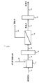
- FIG. 1 An outline of an example of the water treatment apparatus according to the embodiment of the present invention is shown in FIG. 1, and the configuration thereof will be described.
- the water treatment device 1 shown in FIG. 1 has a filtration treatment device 12 as a filtration treatment means for filtering the water to be treated with a separation membrane, and reverse osmosis that separates the filtered water into permeated water and concentrated water with a reverse osmosis membrane.
- a reverse osmosis membrane treatment apparatus 14 is provided as the membrane treatment means.
- the water treatment device 1 may include a water tank 10 to be treated for storing water to be treated.
- a water treatment pipe 16 is connected to the inlet of the water tank 10 to be treated.
- the outlet of the water tank 10 to be treated and the inlet of the filtration treatment device 12 are connected by a water supply pipe 18 to be treated.
- the outlet of the filtration treatment device 12 and the inlet on the primary side of the reverse osmosis membrane treatment device 14 are connected by a filtration treatment water pipe 20.
- a permeated water pipe 22 is connected to the permeated water outlet on the secondary side of the reverse osmosis membrane treatment device 14.
- a concentrated water pipe 24 is connected to the concentrated water outlet on the primary side of the reverse osmosis membrane treatment device 14.
- An iodine-based oxidant-adding pipe 26 is connected to the water tank 10 to be treated as an iodine-based oxidant-adding means for adding an iodine-based oxidant to the water to be treated.
- the water to be treated is sent to the water tank 10 to be treated as needed through the water pipe 16 to be treated and stored.
- the iodine-based oxidant is added to the water to be treated through the iodine-based oxidant addition pipe 26, and the iodine-based oxidant is present (iodine-based oxidant addition step).
- the iodine-based oxidant may be added in the preceding stage of the filtration treatment device 12, may be added in the water treatment pipe 16, or may be added in the water treatment water supply pipe 18.
- the water to be treated to which the iodine-based oxidant is added is sent to the filtration treatment device 12 through the water supply pipe 18 to be treated, and is filtered by the separation membrane in the filtration treatment device 12 to be turbidized (filtration treatment step). ..
- the filtered filtered water is supplied to the reverse osmosis membrane treatment device 14 through the filtration treated water pipe 20, and is separated into permeated water and concentrated water by the reverse osmosis membrane in the reverse osmosis membrane treatment device 14 (reverse). Penetration membrane treatment step).
- the permeated water obtained by the reverse osmosis membrane treatment is discharged through the permeated water pipe 22.
- the concentrated water obtained by the reverse osmosis membrane treatment is discharged through the concentrated water pipe 24.
- the iodine-based oxidant permeates the separation membrane, and the iodine-based oxidant is contained in the water to be treated of the separation membrane as a bactericidal agent, that is, the iodine-based oxidant is used.
- the iodine-based oxidant is used.
- the separation membrane examples include a nanofiltration membrane (NF membrane), a microfiltration membrane (MF membrane), an ultrafiltration membrane (UF membrane), a reverse osmosis membrane (FO membrane), and the like.
- NF membrane nanofiltration membrane
- MF membrane microfiltration membrane
- UF membrane ultrafiltration membrane
- FO membrane reverse osmosis membrane
- the water treatment method and the water treatment apparatus according to the present embodiment can be preferably applied.
- Polyamide-based reverse osmosis membranes and the like have relatively low resistance to oxidizing agents, and continuous contact of free chlorine and the like with polyamide-based reverse osmosis membranes and the like causes a significant decrease in membrane performance.
- an iodine-based oxidizing agent is added to the water to be treated, such a remarkable deterioration in membrane performance is unlikely to occur even in a polyamide reverse osmosis membrane or the like.
- the total iodine CT value (mg / L ⁇ h) represented by (total iodine (mg / L) in the water to be treated) ⁇ (addition time (h) of the iodine-based oxidant) is , 1.25 (mg / L ⁇ h) or less, and more preferably 1.0 (mg / L ⁇ h) or less.
- the total iodine CT value (mg / L ⁇ h) is 1.25 (mg / L ⁇ h) or less, the permeation of the iodine-based oxidant in the reverse osmosis membrane can be further suppressed, so that the permeated water It is possible to suppress the deterioration of water quality.
- the membrane pore size of the separation membrane is preferably 0.01 ⁇ m or more, and more preferably 0.1 ⁇ m or more and 100 ⁇ m or less. If the membrane pore size of the separation membrane is less than 0.01 ⁇ m, the transmittance of total iodine may decrease, and if it exceeds 100 ⁇ m, the fine particles cannot be completely removed, which may adversely affect the reverse osmosis membrane.
- the iodine-based oxidant is an oxidant containing iodine.
- the "iodine" contained in the iodine-based oxidizing agent may be in any form, and can be used as an organic solvent such as molecular iodine, iodide, polyiodine, iodic acid, hypoiodic acid, hydrogen iodide, polyvinylpyrrolidone and cyclodextrin. Any one of the coordinated iodines, or a combination thereof may be used.
- solid iodine is dissolved in a non-polar solvent such as benzene or carbon tetrachloride or alcohols, dissolved with an alkaline agent and water, or A method of dissolving iodide and water may be used, or total iodine may be obtained by adding an acid or an oxidizing agent to a solution containing at least one of iodide and iodide ions.
- a non-polar solvent such as benzene or carbon tetrachloride or alcohols
- alkaline agent and water or A method of dissolving iodide and water may be used, or total iodine may be obtained by adding an acid or an oxidizing agent to a solution containing at least one of iodide and iodide ions.
- polyvinylpyrrolidone or cyclodextrin or cyclodextrin is used.
- Iodine coordinated with an organic solvent such as dextrin may be obtained.
- the iodine-based oxidant is preferably a solid iodine dissolved in iodide salt and water without using an organic substance from the viewpoint of handleability and the influence of water quality on the water to be treated and the treated water.
- Iodine has low solubility in water, and solid iodine dissolved in iodide salt and water provides a stable one-component oxidant with a relatively high concentration and is easy to handle.
- the iodide refers to an iodine compound having an oxidation number of 1, and examples thereof include potassium iodide, sodium iodide, hydrogen iodide, and silver iodide.
- iodides naturally dissociate when dissolved in water and become iodide ions.
- the iodide salt include inorganic iodide salts such as sodium iodide and potassium iodide, and potassium iodide is preferably used.
- An iodine removing means for removing an iodine component in the permeated water may be further provided after the reverse osmosis membrane treatment device 14.
- An example of such a configuration is shown in FIG.
- the water treatment device 2 shown in FIG. 2 has a filtration treatment device 12 as a filtration treatment means for filtering the water to be treated with a separation membrane, and a reverse osmosis device that separates the filtered water into permeated water and concentrated water with a reverse osmosis membrane.
- a reverse osmosis membrane treatment device 14 is provided as the membrane treatment means, and an iodine removal device 28 is provided as an iodine removal means for removing the iodine component in the permeated water of the reverse osmosis membrane.
- the water treatment device 2 may include a water tank 10 to be treated for storing the water to be treated.
- the water treatment pipe 16 is connected to the inlet of the water tank 10 to be treated.
- the outlet of the water tank 10 to be treated and the inlet of the filtration treatment device 12 are connected by a water supply pipe 18 to be treated.
- the outlet of the filtration treatment device 12 and the inlet on the primary side of the reverse osmosis membrane treatment device 14 are connected by a filtration treatment water pipe 20.
- the permeated water outlet on the secondary side of the reverse osmosis membrane treatment device 14 and the inlet of the iodine removing device 28 are connected by a permeated water pipe 22.
- a concentrated water pipe 24 is connected to the concentrated water outlet on the primary side of the reverse osmosis membrane treatment device 14.
- a treated water pipe 30 is connected to the outlet of the iodine removing device 28.
- An iodine-based oxidant-adding pipe 26 is connected to the water tank 10 to be treated as an iodine-based oxidant-adding means for adding an iodine-based oxidant to the water to be treated.
- the water to be treated is sent to the water tank 10 to be treated as needed through the water pipe 16 to be treated and stored.
- the iodine-based oxidant is added to the water to be treated through the iodine-based oxidant addition pipe 26, and the iodine-based oxidant is present (iodine-based oxidant addition step).
- the iodine-based oxidant may be added in the preceding stage of the filtration treatment device 12, may be added in the water treatment pipe 16, or may be added in the water treatment water supply pipe 18.
- the water to be treated to which the iodine-based oxidant is added is sent to the filtration treatment device 12 through the water supply pipe 18 to be treated, and is filtered by the separation membrane in the filtration treatment device 12 to be turbidized (filtration treatment step). ..
- the filtered filtered water is supplied to the reverse osmosis membrane treatment device 14 through the filtration treated water pipe 20, and is separated into permeated water and concentrated water by the reverse osmosis membrane in the reverse osmosis membrane treatment device 14 (reverse). Penetration membrane treatment step).
- the permeated water obtained by the reverse osmosis membrane treatment is sent to the iodine removing device 28 through the permeating water pipe 22, and the iodine component in the permeated water is removed by the iodine removing device 28 (iodine removing step), and then the treated water. It is discharged through the pipe 30.
- the concentrated water obtained by the reverse osmosis membrane treatment is discharged through the concentrated water pipe 24.
- the iodine removing means one or more of the addition of a reducing agent, activated carbon, anion exchanger, scrubber, and degassing membrane may be used, and activated carbon and anion exchanger are preferably used.
- a reducing agent activated carbon
- anion exchanger either an activated carbon filter or an activated carbon filter may be used, and an activated carbon filter is preferable.
- anion exchange body either a weak anion exchange resin or a strong anion exchange resin may be used, and a strong anion exchange resin is preferable.
- iodine is used to evaluate the adsorption performance of activated carbon and that activated carbon is used to remove radioactive iodine. It has never been installed unless it is clear that total iodine permeates the osmosis membrane. In addition, the anion exchanger has never been installed to remove total iodine that has permeated through the permeation water pipe of the reverse osmosis membrane, as with activated carbon.
- continuous addition of the iodine-based oxidant may be performed, or the addition period for adding the iodine-based oxidant to the water to be treated and iodine in the water to be treated.
- Intermittent addition may be provided with an addition-free period in which no system oxidizing agent is added. That is, in the intermittent addition, a step of adding an iodine-based oxidizing agent to the water to be treated and supplying the water to be treated to the filtration treatment device 12, and a step of filtering the water to be treated without adding an iodine-based oxidizing agent to the water to be treated.
- It includes a step of supplying to the processing apparatus 12. Since the bactericidal power of the iodine-based oxidant is extremely high and the bactericidal effect can be obtained in an extremely short time, the slime-suppressing effect of the separation membrane and the reverse osmosis membrane is sufficient by intermittently containing the iodine-based oxidant in the water to be treated. Is obtained.
- the addition period is continuously 10 seconds or more and 3 hours or less, and the additive-free period is continuously 5 seconds or more and less than 1440 minutes.
- the addition period is continuously 10 seconds or more and less than 10 minutes, and the additive-free period is continuously 1 minute or more and less than 1440 minutes. If the addition period is too long, the membrane may be adversely affected, and if the addition period is too long, the slime-causing microorganisms may grow significantly.
- the load on the iodine removing means can be reduced by passing water through the iodine removing means only during the period when total iodine is detected in the permeated water of the reverse osmosis membrane, and the addition can be performed. It is possible to apply a water treatment method for draining the permeated water out of the system while total iodine is detected in the permeated water during the period.
- An example of a water treatment apparatus having such a configuration is shown in FIG.
- a water treatment pipe 16 is connected to the inlet of the water tank 10 to be treated.
- the outlet of the water tank 10 to be treated and the inlet of the filtration treatment device 12 are connected by a water supply pipe 18 to be treated.
- the outlet of the filtration treatment device 12 and the inlet on the primary side of the reverse osmosis membrane treatment device 14 are connected by a filtration treatment water pipe 20.
- a permeated water pipe 22 is connected to the permeated water outlet on the secondary side of the reverse osmosis membrane treatment device 14, and a concentrated water pipe 24 is connected to the concentrated water outlet on the primary side.
- the pipe 27 branched from the permeated water pipe 22 is connected to the inlet of the iodine removing device 28, and the pipe 29 is connected to the outlet of the iodine removing device 28.
- An iodine-based oxidant-adding pipe 26 is connected to the water tank 10 to be treated as an iodine-based oxidant-adding means for adding an iodine-based oxidant to the water to be treated.
- the water to be treated is sent to the water tank 10 to be treated as needed through the water pipe 16 to be treated and stored.
- the water to be treated is sent to the filtration treatment device 12 through the water supply pipe 18 to be treated, and is filtered by the separation membrane in the filtration treatment device 12.
- the filtered filtered water is supplied to the reverse osmosis membrane treatment device 14 through the filtration treated water pipe 20, and is separated into permeated water and concentrated water by the reverse osmosis membrane in the reverse osmosis membrane treatment device 14 (reverse).
- Penetration membrane treatment step The permeated water obtained by the reverse osmosis membrane treatment is discharged through the permeated water pipe 22, and the concentrated water is discharged through the concentrated water pipe 24.
- the iodine-based oxidant is added to the water to be treated through the iodine-based oxidant addition pipe 26 in the water tank 10 to be treated, and the iodine-based oxidant is present.
- the iodine-based oxidant may be added in the water treatment pipe 16 or in the water supply pipe 18 to be treated.
- the water to be treated to which the iodine-based oxidant is added is sent to the filtration treatment device 12 through the water supply pipe 18 to be treated, and is filtered by the separation membrane in the filtration treatment device 12 to be turbidized (filtration treatment step). ).
- the filtered filtered water is supplied to the reverse osmosis membrane treatment device 14 through the filtration treated water pipe 20, and is separated into permeated water and concentrated water by the reverse osmosis membrane in the reverse osmosis membrane treatment device 14 (reverse). Penetration membrane treatment step).
- the permeated water containing total iodine obtained by the reverse osmosis membrane treatment was sent to the iodine removing device 28 through the permeating water pipes 22 and 27, and the iodine component in the permeated water was removed by the iodine removing device 28 (iodine). After the removal step), it is discharged through the pipe 29.
- the concentrated water obtained by the reverse osmosis membrane treatment is discharged through the concentrated water pipe 24.
- total chlorine is a concentration determined by an absorptiometry using N, N-diethyl-p-phenylenediammonium (DPD) sulfate described in "33. Residual chlorine of JIS K 0120: 2013". Point to.
- a 0.2 mol / L potassium dihydrogen phosphate solution is placed in 50 mL of a colorimetric tube, and 1.0 g of DPD diluted powder (1.0 g of N, N-diethyl-p-phenylenediammonium sulfate is crushed therein, and sodium sulfate is added.
- Add 0.5 g (a mixture of 24 g) add 0.5 g of potassium iodide, add an appropriate amount of sample, add water up to the marked line to dissolve, and leave to stand for about 3 minutes.
- the developed pink to magenta is quantified by measuring the absorbance at a wavelength of around 510 nm (or 555 nm).
- DPD is oxidized by any oxidizing agent, and examples of the oxidizing agent include chlorine, bromine, iodine, hydrogen peroxide, ozone, and the like, which can be measured.
- the iodine oxidizing agent in the present embodiment all forms of iodine can have oxidizing power (e.g. I 2, IO 3 -, IO -, HI) together, was measured as “total chlorine”.
- residual total chlorine concentration in concentrated water is "total chlorine concentration detected after the residence time from the point where the iodine-based oxidant is added until it is obtained as concentrated water in the reverse osmosis membrane”. ".
- the concentration detected after starting the addition of the iodine-based oxidant is used in consideration of the residence time from the point where the iodine-based oxidant is added until the concentration water of the reverse osmosis membrane is obtained. This makes it possible to perform more accurate operation management.
- the residual total chlorine concentration in the concentrated water of the reverse osmosis membrane is preferably 0.1 mg / L or more, and more preferably 0.2 mg / L or more.
- the active ingredient in the addition period is greatly consumed due to the growth of microorganisms during the addition period, and the residual total chlorine in the concentrated water of the reverse osmosis membrane is considered. Concentration control becomes even more important.
- the iodine-based oxidizing agent is an oxidizing agent in which iodine is dissolved using an iodide salt such as potassium iodide, that is, an oxidizing agent containing iodine and iodide, iodide with respect to iodine (iodide salt and iodide).
- the molar ratio of (at least one of the ions) (iodide (at least one of the iodide salt and iodide ion) / iodine) is determined from the viewpoint of the cost of added chemicals and the permeation of iodine in the back-penetration membrane. It is preferably 1 to 1.9, and 1.5 to 1.
- total iodide CT value total iodide atom concentration ⁇ addition time
- total iodine yield It is more preferably 9, and further preferably 1.8 to 1.9.
- total iodine atom refers to all iodine existing in all forms regardless of the presence or absence of oxidizing power. As the form for example, I 2, IO 3 -, IO -, HI, I -, I 3 - it is. Total iodine atoms can be measured using ICP-MS.
- Iodine can be dissolved in water or the like by using an iodide salt, but the iodide salt is more expensive than iodine, and the higher the molar ratio of iodide to iodine, the higher the chemical cost. Therefore, iodine
- the molar ratio of iodide to iodide is preferably low. Further, as for the permeation amount with respect to the total iodine CT value added to the separation membrane, the permeation amount is smaller when the molar ratio of iodide to iodine is low, so that the molar ratio of iodide to iodine is preferably low.
- the total iodine yield (total amount of iodine to mixed iodine) will be low, so it is preferable to maintain a molar ratio of a predetermined value or more.
- the pH of the water to be treated is preferably in the range of 2 to 12, more preferably in the range of 4 to 9. If the pH of the water to be treated exceeds 9, the slime suppressing effect is lowered due to the decrease in the active ingredient, and if it exceeds 12, a sufficient slime suppressing effect may not be obtained. If it is less than 2, iodine crystals may be formed. It may precipitate and a sufficient slime suppressing effect may not be obtained.
- the membrane type and operating pressure of the reverse osmosis membrane used in the water treatment apparatus and water treatment method according to the present embodiment may be performed at a pressure at which permeated water can be obtained from the reverse osmosis membrane.
- the reverse osmosis membrane for irrigation (low pressure reverse osmosis membrane) may be operated at 0.2 to 1.2 MPa
- the reverse osmosis membrane for seawater desalination (high pressure reverse osmosis membrane) may be operated at 3 to 5.5 MPa.
- the reverse osmosis membrane for desalination of seawater high pressure reverse osmosis membrane
- the reverse osmosis membrane for desalination of seawater high pressure reverse osmosis membrane
- the chlorine content on the membrane surface of the reverse osmosis membrane is preferably 0.1 atom% or more, and more preferably 0.5 atom% or more. If the chlorine content on the membrane surface of the reverse osmosis membrane is less than 0.1 atom%, the amount of permeated water may decrease.
- the chlorine content of the reverse osmosis membrane surface can be measured by X-ray electron spectroscopy.
- the water to be treated of the water treatment method and the filtration treatment device 12 in the water treatment device according to the present embodiment may be the water to be treated containing an organic substance or the water to be treated containing an organic substance and a nitrogen compound.
- the water to be treated containing organic substances is, for example, treated water obtained from wastewater treatment means.
- wastewater treatment means any of biological treatment, coagulation sedimentation, pressure flotation, sand filtration, biological activated carbon and the like may be used, or may be used in combination.
- the water to be treated may be biologically treated water obtained from a biological treatment means (biological treatment step).
- the water treatment method and the water treatment apparatus according to the present embodiment are particularly applied to wastewater recovery, for example, application to collection of electronic industrial wastewater, food production wastewater, drinking water production wastewater, chemical factory wastewater, plating factory wastewater, and the like. Can be considered.
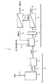
- the recovered water of the electronic industrial wastewater often contains ammonia, and as a flow for recovering the wastewater, for example, in the latter stage of the biological treatment system 50 provided with the biological treatment device 36 as shown in FIG.
- a flow having a water treatment device 1 including a filtration treatment device 12 and a reverse osmosis membrane treatment device 14 to which the water treatment device and the water treatment method are applied can be considered.
- the water treatment system 4 shown in FIG. 4 includes, for example, a biological treatment device 36, a biological treatment water tank 38, and the water treatment device 1 as biological treatment means.
- the water treatment system 4 may include a second reverse osmosis membrane treatment device 31 as the second reverse osmosis membrane treatment means.
- the raw water pipe 40 is connected to the inlet of the biological treatment device 36.
- the outlet of the biological treatment device 36 and the inlet of the biological treatment water tank 38 are connected by a biological treatment water pipe 42.
- the outlet of the biological treatment water tank 38 and the inlet of the water treatment tank 10 are connected by a water treatment water pipe 16.
- the outlet of the water tank 10 to be treated and the inlet of the filtration treatment device 12 are connected by a water supply pipe 18 to be treated.
- the outlet of the filtration treatment device 12 and the inlet on the primary side of the reverse osmosis membrane treatment device 14 are connected by a filtration treatment water pipe 20.
- a permeated water pipe 22 is connected to the permeated water outlet on the secondary side of the reverse osmosis membrane treatment device 14.
- the concentrated water outlet on the primary side of the reverse osmosis membrane treatment device 14 and the inlet on the primary side of the second reverse osmosis membrane treatment device 31 are connected by a concentrated water pipe 24.
- a concentrated water pipe 34 is connected to the concentrated water outlet on the primary side of the second reverse osmosis membrane treatment device 31, and the permeated water outlet on the secondary side of the second reverse osmosis membrane treatment device 31 and the permeation of the water tank 10 to be treated. It is connected to the water inlet by a permeated water pipe 32.
- An iodine-based oxidant addition pipe 54 is connected to the water tank 10 to be treated as an iodine-based oxidant addition means for adding an iodine-based oxidant to the water to be treated.
- the biological treatment device 36 performs biological treatment (biological treatment step).
- the biologically treated biologically treated water is stored in the biologically treated water tank 38 as needed through the biologically treated water pipe 42, and then is required for the treated water tank 10 of the water treatment apparatus 1 through the treated water pipe 16 as the water to be treated.
- the liquid is sent and stored accordingly.
- the iodine-based oxidant is added to the water to be treated through the iodine-based oxidant addition pipe 54 to make the iodine-based oxidant present (iodine-based oxidant addition step).
- the iodine-based oxidant may be added in the biologically treated water pipe 42, in the biologically treated water tank 38, in the treated water pipe 16, or in the treated water supply pipe 18. May be added in.
- the water to be treated to which the iodine-based oxidant is added is sent to the filtration treatment device 12 through the water supply pipe 18 to be treated, and is filtered by the separation membrane in the filtration treatment device 12 to be turbidized (filtration treatment step). ).
- the filtered filtered water is supplied to the reverse osmosis membrane treatment device 14 through the filtration treated water pipe 20, and is separated into permeated water and concentrated water by the reverse osmosis membrane in the reverse osmosis membrane treatment device 14 (reverse). Penetration membrane treatment step).
- the permeated water obtained by the reverse osmosis membrane treatment is discharged through the permeated water pipe 22.
- the concentrated water obtained by the reverse osmosis membrane treatment is discharged through the concentrated water pipe 24.
- the concentrated water obtained by the reverse osmosis membrane treatment may be sent to the second reverse osmosis membrane treatment apparatus 31 as needed, and the second reverse osmosis membrane treatment apparatus 31 may further perform the reverse osmosis membrane treatment ().
- the concentrated water obtained by the second reverse osmosis membrane treatment is discharged to the outside of the system through the concentrated water pipe 34.
- the permeated water obtained by the second reverse osmosis membrane treatment may be discharged to the outside of the system, or may be sent to the water tank 10 to be treated through the permeated water pipe 32 and circulated as needed.
- a biological treatment system 50 having a biological treatment device 36 and a biological treatment water tank 38 individually is illustrated, but a membrane separation activated sludge device (MBR) in which these are integrated into one unit is used. May be good.
- MLR membrane separation activated sludge device
- a second reverse osmosis membrane treatment device 31 (brine reverse osmosis membrane) in order to increase the water recovery rate.
- the second reverse osmosis membrane treatment device 31 uses the concentrated water of the reverse osmosis membrane treatment device 14 as the water to be treated, and for example, returns the permeated water to the water tank 10 to be treated and discharges the concentrated water to the outside of the system.
- biological treatment has been described as an example of pretreatment for reverse osmosis membrane treatment, but in the pretreatment step for reverse osmosis membrane treatment, biological treatment, aggregation treatment, aggregation precipitation treatment, and pressure levitation have been described.
- Biological, physical or chemical pretreatments such as treatments, filtration treatments, membrane separation treatments, activated charcoal treatments, ozone treatments, UV irradiation treatments, and combinations of two or more of these pretreatments as required. May be done.
- a pump in addition to the back-penetrating film, a pump, a safety filter, a flow rate measuring device, a pressure measuring device, a temperature measuring device, an oxidation-reduction potential (ORP) measuring device, a residual chlorine measuring device, and an electric conductivity
- a measuring device a pH measuring device, an energy recovery device and the like may be provided as needed.
- a scale inhibitor other than the iodine-based oxidant and a pH adjuster are added to at least one of the biological treatment water tank 38 and the pipes before and after it, and the water tank 10 to be treated and the pipes before and after it. In one, it may be added to at least one of the biologically treated water and the water to be treated.
- the water treatment apparatus and water treatment method according to this embodiment may be applied to, for example, pure water production.
- a flow in which an iodine removing device 28 as an iodine removing means is provided after the pure water production can be considered.
- the water treatment system 5 shown in FIG. 5 includes, for example, a sand filtration device 60 as a filtration treatment means, a filtration water tank 62, a filtration treatment device 64 as a filtration treatment means, an ion exchange treatment device as an ion removal means, and electric desalting. It includes an ion removing device 78 such as a processing device (EDI) and a membrane filtration device 80 having an ultrafiltration membrane (UF membrane) or the like as a membrane filtration means.
- the water treatment system 5 may include a second reverse osmosis membrane treatment device 31 as the second reverse osmosis membrane treatment means.
- the raw water pipe 66 is connected to the inlet of the sand filtration device 60.
- the outlet of the sand filtration device 60 and the inlet of the filtered water tank 62 are connected by a filtered water pipe 68.
- the outlet of the filtered water tank 62 and the inlet of the filtration processing device 64 are connected by a filtered water supply pipe 70.
- the outlet of the filtration treatment device 64 and the inlet on the primary side of the reverse osmosis membrane treatment device 14 are connected by a filtration treatment water pipe 72.
- the permeated water outlet on the secondary side of the reverse osmosis membrane treatment device 14 and the inlet of the iodine removing device 28 are connected by a permeated water pipe 22.
- the outlet of the iodine removing device 28 and the ion removing device 78 are connected by a treated water pipe 30.
- the outlet of the ion removing device 78 and the inlet of the membrane filtration device 80 are connected by an ion removing treated water pipe 82.
- a treated water pipe 84 is connected to the outlet of the membrane filtration device 80.
- the concentrated water outlet on the primary side of the reverse osmosis membrane treatment device 14 and the inlet on the primary side of the second reverse osmosis membrane treatment device 31 are connected by a concentrated water pipe 24.
- a concentrated water pipe 34 is connected to the concentrated water outlet on the primary side of the second reverse osmosis membrane treatment device 31, and the permeated water outlet on the secondary side of the second reverse osmosis membrane treatment device 31 and the filtered water pipe 72. Are connected by a permeated water pipe 32.
- a reducing agent addition pipe 74 is connected to the filtered water tank 62 as a reducing agent addition means.
- An iodine-based oxidant-adding pipe 76 is connected to the filtered water supply pipe 70 as an iodine-based oxidant-adding means for adding an iodine-based oxidant to the water to be treated.
- raw water is sent to the sand filtration device 60 through the raw water pipe 66, and the sand filtration device 60 performs the filtration treatment (filtration treatment step).
- the filtered filtered water is stored in the filtered water tank 62, the reducing agent is supplied through the reducing agent addition pipe 74 in the filtered water tank 62, and then the liquid is sent to the filtering treatment device 64, and the separation membrane is supplied in the filtering water tank 62. It is filtered and turbidized in (filtration treatment step).
- the filtered filtered water is supplied to the reverse osmosis membrane treatment device 14 through the filtered water pipe 72.
- the iodine-based oxidant is added to the water to be treated through the iodine-based oxidant-adding pipe 76 to allow the iodine-based oxidant to exist (iodine-based oxidant addition step).
- the filtered filtered water is separated into permeated water and concentrated water by the reverse osmosis membrane in the reverse osmosis membrane treatment apparatus 14 (reverse osmosis membrane treatment step).
- the permeated water obtained by the reverse osmosis membrane treatment is sent to the iodine removing device 28 through the permeating water pipe 22, and the iodine component in the permeated water is removed by the iodine removing device 28 (iodine removing step), and then the treated water.
- the liquid is sent to the ion removing device 78 through the pipe 30, and the ion removing process is performed in the ion removing device 78 (ion removing process step).
- the ion-removed treated water that has been subjected to the ion-removing treatment is sent to the membrane filtration device 80 through the ion-removing treated water pipe 82, and the membrane filtration treatment is performed in the membrane filtration device 80 (membrane filtration treatment step).
- the membrane filtration treated water subjected to the membrane filtration treatment is discharged through the treated water pipe 84.
- the concentrated water obtained by the reverse osmosis membrane treatment may be sent to the second reverse osmosis membrane treatment apparatus 31 as needed, and the second reverse osmosis membrane treatment apparatus 31 may further perform the reverse osmosis membrane treatment (). Second reverse osmosis membrane treatment step).
- the concentrated water obtained by the second reverse osmosis membrane treatment is discharged to the outside of the system through the concentrated water pipe 34.
- the permeated water obtained by the second reverse osmosis membrane treatment may be discharged to the outside of the system, or may be sent to the filtered water pipe 72 through the permeated water pipe 32 and circulated as needed.
- the slime inhibitor for a membrane according to the present embodiment contains water, iodine and iodide.
- the slime inhibitor for a membrane according to the present embodiment is, for example, a slime inhibitor used for slime suppression in water treatment using a separation membrane by the above water treatment apparatus and a water treatment method and a reverse osmosis membrane in the subsequent stage. be.
- the slime inhibitor for this membrane contains water, iodine and iodide, and the molar ratio of iodide to iodine is preferably in the range of 1 to 1.9 as described above.
- the slime inhibitor preferably has a pH of 3 or more and 9 or less, more preferably 3 or more and 7 or less, and further preferably 4 or more and 6.5. If the pH is less than 3, iodine crystals may precipitate, and if the pH exceeds 9, the active ingredient may be significantly reduced.
- the slime inhibitor has high stability at a high concentration, and the total iodine concentration is preferably 3% by mass or more, and is in the range of 3% by mass or more and 40% by mass or less. It is more preferable to be in the range of 10% by mass or more and 25% by mass or less.
- Example 1 [Penetration test, bactericidal effect test]
- the microfiltration membrane which is a turbidizing membrane, can be sterilized by allowing the iodine-based oxidant (water + iodine + potassium iodide) to permeate.
- Test water Sagamihara well water (dechlorination treatment, bacterial count 2 ⁇ 10 3 CFU / mL)
- Drug Iodine-based oxidant (3) -Depletion film pore size: 0.01 ⁇ m (polyvinylidene fluoride (PVDF)), 0.02 ⁇ m (PVDF), 0.05 ⁇ m (PVDF), 0.1 ⁇ m (polysulfone), 0.2 ⁇ m (polysulfone), 1. 0 ⁇ m (polypropylene), 10 ⁇ m (polypropylene) -Test water pH: 7.0
- Iodine-based oxidant (3) Iodine, potassium iodide, and water were mixed and prepared according to the compounding composition (mass%) shown in Table 1. The pH, total iodine (% by mass), and total iodine yield of the composition were as shown in Table 1. The total chlorine concentration was measured using a HACH multi-item water quality analyzer DR / 3900 and converted to total iodine.
- iodide was dissolved in water with stirring, iodine was added to a substantially uniform solution, and the mixture was stirred for about 30 minutes to prepare a substantially uniform iodine-based oxidizing agent (3). ..
- Iodine-based oxidant was added to the water to be treated and treated with a turbid film.
- Table 2 shows the transmittance (%) of total iodine 5 minutes after the start of addition.
- the number of bacteria in the test water before the addition of the drug was measured, and after the drug was added to the test water, the number of bacteria in the filtered water was measured to confirm the bactericidal effect.
- the number of bacteria was measured using Sheet Check R2A (manufactured by NIPRO).
- the total iodine transmittance was 88% or more.
- Met The number of bacteria in the permeated water decreased to ⁇ 10 in all cases.
- the total iodine CT value in Examples 1-1 to 1-7 was 0.15 mg / L ⁇ h.
- Test water Sagamihara well water (dechlorination treatment, bacterial count 2 x 10 3 CFU / mL)
- Drug Iodine-based oxidant (3) pH: 7.0
- Reverse osmosis membrane ES20, ESPA2, LFC3, TML10D
- the number of bacteria in the permeated water decreased to ⁇ 10 regardless of the total iodine concentration in the water to be treated. It was possible to suppress the generation of slime on both the separation membrane and the reverse osmosis membrane by a simple method.
- a high total iodine concentration was detected in the permeated water due to the high CT value.
- the total iodine concentration in the permeated water could be suppressed. It is considered that the difference in total iodine transmittance due to the difference in CT value of the reverse osmosis membrane is due to the high adsorptivity of iodine and the polymer membrane.
- iodine has high adsorptivity and is particularly easily adsorbed on polymer substances.It is considered that iodine is adsorbed on the polymer film by the same mechanism and the permeation amount changes according to the adsorption amount.
- the present inventors have clarified that the amount of adsorption is determined by the total iodine concentration in the water to be treated and the addition time. Furthermore, it has been confirmed that uncharged iodine is effectively removed by removal with a strong anion exchange resin, which will be described later, and it is considered that the adsorption mechanism functions more effectively due to the polyamide-based polymer.
- the adsorbed iodine When the adsorbed iodine exceeds a certain CT value, it will be detected on the permeation side, and if it is less than that CT value, the addition of the drug will be stopped, and by having an addition-free period, iodine will move to the concentrated water side during the addition-free period. It is discharged.
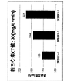
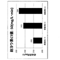
- Acetic acid was added to the water supply to the reverse osmosis membrane to make test water, and a test was conducted to promote slime production.
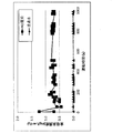
- the start time of addition of acetic acid and slime inhibitor was set to 0 hour, and the increase value of the differential pressure after the addition was obtained. The results are shown in FIG.
- Comparative Experimental Example 1 when the reverse osmosis membrane was operated without adding a slime inhibitor to the test water, the differential pressure increased significantly about 80 hours after the start of acetic acid addition, and biofouling due to slime formation occurred. I understand. In Comparative Experimental Example 2, the differential pressure gradually increased from about 150 hours after the start of addition of the acetic acid and slime inhibitor. In Experimental Example 1, no large increase in differential pressure was confirmed, and it was shown that a sufficient slime suppressing effect could be obtained, and reverse osmosis required as "(1- (permeated water conductivity / supplied water conductivity)) x 100" was obtained. The initial value of the membrane exclusion rate (%) was 98.5%, and after the end of the test, it was 98.5%, and no decrease was observed.
- Test water Sagamihara well water (dechlorinated treated water)
- Test equipment Reverse osmotic membrane element test equipment-Drug: The molar ratio of iodide to iodine (iodine / iodine) was determined by the same method as for the iodine-based oxidant (3) with the compounding composition (mass%) shown in Table 1.
- Total iodine atoms were measured using ICP-MS (PerkinElmer, ELAN DRC-e ICP mass spectrometer). A sufficient amount of sodium thiosulfate was added to the sample water, all iodine was reduced, and the pH was adjusted to 9 to 10 using aqueous ammonia to stabilize the ions before measurement. The calibration curve was prepared using potassium iodate.
- the permeation iodine concentration decreases as the molar ratio of iodide to iodine decreases. .. It can be seen that it is effective to reduce the molar ratio of iodide to iodine in order to suppress the permeation of iodine.
- the total iodine yield was 100% for the iodine-based oxidizing agents (1) to (4), but 94% and 93% for the iodine-based oxidizing agents (5) and (6), and 94% and 93% for the iodine-based oxidizing agents (7). It was 92%. It is easy to imagine that a higher total iodine yield is better, 90% or more is better, and 100% is best. It can be seen that it is most desirable to set the molar ratio of iodide to 1.8 in order to suppress the permeation of iodine and obtain a high total iodine yield.
- the storage stability is very high for all iodine-based oxidants, the active ingredient retention rate after 90 days of storage at room temperature (25 ° C) is 99%, and the active ingredient retention rate after 90 days of storage at 50 ° C is 99%. there were.
- a sufficient slime suppressing effect can be obtained by intermittent addition, the chemical cost is reduced, the permeation amount of total iodine is reduced, and the molar ratio of iodide to iodine is 1.5 to 3. It was possible to suppress the permeation amount of iodine and suppress the influence on the subsequent equipment.
- Test water Sagamihara well water (dechlorinated treated water)
- Reverse osmosis membrane 4-inch reverse osmosis membrane element ESPA2 (manufactured by Nitto Denko)
- -Iodine remover In Experimental Example 7, strong anion exchanger (Amberlite IRA-400HG OH type, styrene / divinylbenzene copolymer / gel type, harmonic mean diameter 0.55 to 0.75 mm, total exchange capacity ⁇ 1.40 eq / L / wet resin) was used.
- -Drug In Experimental Example 7, an iodine-based oxidizing agent (7) was used.
- -Addition method The treated water obtained by adding an iodine-based oxidizing agent to the test water was passed through an iodine removing device under the condition of SV50.
- Test water Pure water Chemicals: Iodine-based oxidizer (3)
- Test water temperature 20 ° C (room temperature control)
- Storage state Stirring with stirrer (Experimental example 7-1: Open system, Experimental example 7-2: Open system, aeration, Comparative experimental example 4: Closed system)
- a cooling tower or scrubber which is a gas-liquid mixing system water treatment system, is considered to be suitable as the iodine removal device.
- Test Water adding bouillon to Sagamihara well water (dechlorination), for about 48 hours at 30 ° C., and the number of bacteria and 10 7 (CFU / mL).
- Water temperature 25 ° C (room temperature control) -PH: 7.0 -Drug:
- the effective chlorine concentration was adjusted to 1.0 mg / L using chlorosulfamic acid (prepared by the method below), and in Comparative Experimental Example 6, a stabilized hypobromous acid compound (prepared by the following method) was used.
- the total chlorine concentration was adjusted to 0.25 mg / L, and in Experimental Example 8, the iodine-based oxidizing agent (3) was used, and the total chlorine content was 0.04 mg / L and 0.05 mg / L, respectively. It was added so as to be L, 0.1 mg / L (0.14 mg / L, 0.18 mg / L, 0.36 mg / L as total iodine).
- a composition was prepared by mixing 12% aqueous sodium hypochlorite solution: 50% by mass, sulfamic acid: 10% by mass, sodium hydroxide: 10% by mass, and water: residue.
- the pH of the composition was 14, and the total chlorine concentration was 6% by mass.
- the pH of the resulting solution was 14 as measured by the glass electrode method.
- the bromine content of the resulting solution was 16.9% as measured by the method of converting bromine to iodine with potassium iodide and then oxidatively reducing titration with sodium thiosulfate, and the theoretical content (16.9%). ) was 100.0%.
- the oxygen concentration in the reaction vessel during the bromine reaction was measured using "Oxygen Monitor JKO-02 LJDII" manufactured by Jiko Co., Ltd.
- the bromic acid concentration was less than 5 mg / kg.
- the pH was measured under the following conditions. Electrode type: Glass electrode type pH meter: HM-42X type manufactured by Toa DKK Co., Ltd.
- Electrode calibration Kanto Kagaku Co., Ltd. phthalate pH (4.01) standard solution (type 2), neutral phosphate pH Measurement temperature performed by two-point calibration of (6.86) standard solution (type 2) and the company's borate pH (9.18) standard solution (type 2): 25 ° C. Measured value: The electrode is immersed in the measuring solution, and the value after stabilization is used as the measured value, which is the average value of three measurements.
- the number of bacteria in the test water before the addition of the drug was measured, the drug was added to the test water, and 10 minutes later, the number of bacteria was measured to test the bactericidal activity.
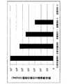
- the number of bacteria was measured using San-Ai Bio Checker TTC (manufactured by San-Ai Oil Co., Ltd.). The results are shown in FIG.
- Comparative Experimental Example 5 a test was conducted using chlorosulfamic acid, and almost no bactericidal effect was obtained.
- Comparative Example 6 were tested using the stabilized hypobromous acid composition, the number of bacteria was reduced to 3 ⁇ 10 6.
- Experimental Examples 8-1, 8-2, and 8-3 when an iodine-based oxidizing agent was added as total chlorine to 0.04 mg / L, 0.05 mg / L, and 0.1 mg / L, respectively, the bacteria were added. The numbers decreased to 3 ⁇ 10 4 , 1 ⁇ 10 3 , and 0, respectively, showing a high bactericidal effect. The strong bactericidal effect was shown even with an extremely short contact time of 10 minutes, indicating that intermittent addition with a shorter drug addition time may be effective.
Landscapes
- Chemical & Material Sciences (AREA)
- Water Supply & Treatment (AREA)
- Engineering & Computer Science (AREA)
- Chemical Kinetics & Catalysis (AREA)
- Environmental & Geological Engineering (AREA)
- Life Sciences & Earth Sciences (AREA)
- Organic Chemistry (AREA)
- Hydrology & Water Resources (AREA)
- Nanotechnology (AREA)
- Health & Medical Sciences (AREA)
- Medicinal Chemistry (AREA)
- Separation Using Semi-Permeable Membranes (AREA)
- Treatment Of Water By Oxidation Or Reduction (AREA)
Abstract
分離膜とその後段の逆浸透膜とを用いる水処理において、簡易な方法で分離膜と逆浸透膜の両方においてスライムが発生することを抑制することができる、水処理方法、水処理装置、および膜用のスライム抑制剤を提供する。被処理水にヨウ素系酸化剤を添加するヨウ素系酸化剤添加工程と、ヨウ素系酸化剤添加工程で得られた被処理水を分離膜でろ過処理するろ過処理工程と、ろ過処理工程で得られたろ過処理水を逆浸透膜で透過水と濃縮水とに分離する逆浸透膜処理工程と、を含む水処理方法である。
Description
本発明は、分離膜とその後段の逆浸透膜とを用いる水処理方法、水処理装置、および膜用のスライム抑制剤に関する。
逆浸透膜(RO膜)等の分離膜を用いる水処理方法において、バイオファウリング抑制(スライム抑制)法として各種殺菌剤(スライム抑制剤)を用いることが知られている。
特許文献1では、次亜塩素酸ナトリウムとヨウ化カリウムの反応生成物であるヨウ素を逆浸透膜装置に導入することによって逆浸透膜装置の生物学的汚染を抑制できることが記載されている。また、特許文献2では、半透膜の性能回復処理方法としてヨウ素および/またはヨウ素化合物が添加されたヨウ素含有溶液を被処理水に添加する方法が記載されている。
逆浸透膜の前処理として、精密ろ過膜や限外ろ過膜などからなる分離膜(除濁膜)を用いる場合があるが、分離膜にスライムが発生することにより、逆浸透膜装置に殺菌剤を導入したとしても分離膜の後段の逆浸透膜にスライムが発生してしまう場合や、殺菌剤の添加量が増加してしまう場合があった。また、特許文献1に記載の方法で次亜塩素酸ナトリウムを用いて分離膜を前処理し、処理水にヨウ化カリウムだけを用いて脱塩素化を図る場合、脱塩素化しきれずに逆浸透膜に次亜塩素酸ナトリウムが流入して膜の劣化を引き起こす可能性があった。
本発明の目的は、分離膜とその後段の逆浸透膜とを用いる水処理において、簡易な方法で分離膜と逆浸透膜の両方においてスライムが発生することを抑制することができる、水処理方法、水処理装置、および膜用のスライム抑制剤を提供することにある。
本発明は、被処理水にヨウ素系酸化剤を添加するヨウ素系酸化剤添加工程と、前記ヨウ素系酸化剤添加工程で得られた被処理水を分離膜でろ過処理するろ過処理工程と、前記ろ過処理工程で得られたろ過処理水を逆浸透膜で透過水と濃縮水とに分離する逆浸透膜処理工程と、を含む、水処理方法である。
前記水処理方法において、前記ヨウ素系酸化剤は、水、ヨウ素およびヨウ化物を含むことが好ましい。
前記水処理方法における前記ヨウ素系酸化剤添加工程において、(前記被処理水中の全ヨウ素(mg/L))×(前記ヨウ素系酸化剤の添加時間(h))で表される全ヨウ素CT値(mg/L・h)が、1.25(mg/L・h)以下であることが好ましい。
前記水処理方法における前記ヨウ素系酸化剤添加工程において、前記被処理水にヨウ素系酸化剤を添加する添加期間と、前記被処理水にヨウ素系酸化剤を添加しない無添加期間と、を設ける間欠添加を行うことが好ましい。
前記水処理方法において、前記添加期間が連続して10秒以上3時間以下であり、前記無添加期間が連続して5秒以上48時間未満であることが好ましい。
前記水処理方法において、前記分離膜の膜孔径が、0.01μm以上であることが好ましい。
前記水処理方法において、前記透過水中のヨウ素成分を除去するヨウ素除去工程をさらに含むことが好ましい。
前記水処理方法において、前記ヨウ素除去工程において、活性炭およびアニオン交換体のうち少なくとも1つを用いることが好ましい。
本発明は、水とヨウ素とヨウ化物とを含む、膜用のスライム抑制剤である。
前記膜用のスライム抑制剤において、pHが、3以上9以下であることが好ましい。
前記膜用のスライム抑制剤において、全ヨウ素が、3質量%以上であることが好ましい。
前記膜用のスライム抑制剤において、前記ヨウ素に対する前記ヨウ化物のモル比は、1~1.9の範囲であることが好ましい。
本発明は、被処理水にヨウ素系酸化剤を添加するヨウ素系酸化剤添加手段と、前記ヨウ素系酸化剤添加手段により得られた被処理水を分離膜でろ過処理するろ過処理手段と、前記ろ過処理手段で得られたろ過処理水を逆浸透膜で透過水と濃縮水とに分離する逆浸透膜処理手段と、を備える水処理装置である。
前記水処理装置において、前記ヨウ素系酸化剤は、水、ヨウ素およびヨウ化物を含むことが好ましい。
前記水処理装置において、前記ヨウ素系酸化剤添加手段は、(前記被処理水中の全ヨウ素(mg/L))×(前記ヨウ素系酸化剤の添加時間(h))で表される全ヨウ素CT値(mg/L・h)が、1.25(mg/L・h)以下となるようにするものであることが好ましい。
前記水処理装置において、前記ヨウ素系酸化剤添加手段は、前記被処理水にヨウ素系酸化剤を添加する添加期間と、前記被処理水にヨウ素系酸化剤を添加しない無添加期間と、を設ける間欠添加を行うものであることが好ましい。
前記水処理装置において、前記添加期間が連続して10秒以上3時間以下であり、前記無添加期間が連続して5秒以上48時間未満であることが好ましい。
前記水処理装置において、前記分離膜の膜孔径が、0.01μm以上であることが好ましい。
前記水処理装置において、前記透過水中のヨウ素成分を除去するヨウ素除去手段をさらに備えることが好ましい。
前記水処理装置において、前記ヨウ素除去手段は、活性炭およびアニオン交換体のうち少なくとも1つであることが好ましい。
本発明により、分離膜とその後段の逆浸透膜とを用いる水処理において、簡易な方法で分離膜と逆浸透膜の両方においてスライムが発生することを抑制することができる、水処理方法、水処理装置、および膜用のスライム抑制剤を提供することができる。
本発明の実施の形態について以下説明する。本実施形態は本発明を実施する一例であって、本発明は本実施形態に限定されるものではない。
<分離膜を用いる水処理装置および水処理方法>
本発明の実施形態に係る水処理装置の一例の概略を図1に示し、その構成について説明する。
本発明の実施形態に係る水処理装置の一例の概略を図1に示し、その構成について説明する。
図1に示す水処理装置1は、被処理水を分離膜でろ過処理するろ過処理手段として、ろ過処理装置12と、ろ過処理水を逆浸透膜で透過水と濃縮水とに分離する逆浸透膜処理手段として、逆浸透膜処理装置14と、を備える。水処理装置1は、被処理水を貯留するための被処理水槽10を備えてもよい。
水処理装置1において、被処理水槽10の入口には、被処理水配管16が接続されている。被処理水槽10の出口と、ろ過処理装置12の入口とは、被処理水供給配管18により接続されている。ろ過処理装置12の出口と、逆浸透膜処理装置14の一次側の入口とは、ろ過処理水配管20により接続されている。逆浸透膜処理装置14の二次側の透過水出口には、透過水配管22が接続されている。逆浸透膜処理装置14の一次側の濃縮水出口には、濃縮水配管24が接続されている。被処理水槽10には、被処理水にヨウ素系酸化剤を添加するヨウ素系酸化剤添加手段として、ヨウ素系酸化剤添加配管26が接続されている。
水処理装置1において、被処理水は、被処理水配管16を通して、必要に応じて被処理水槽10に送液され、貯留される。被処理水槽10において、被処理水中にヨウ素系酸化剤添加配管26を通してヨウ素系酸化剤が添加され、ヨウ素系酸化剤を存在させる(ヨウ素系酸化剤添加工程)。ヨウ素系酸化剤は、ろ過処理装置12の前段において添加されればよく、被処理水配管16において添加されてもよいし、被処理水供給配管18において添加されてもよい。
ヨウ素系酸化剤が添加された被処理水は、被処理水供給配管18を通してろ過処理装置12に送液され、ろ過処理装置12において、分離膜でろ過処理されて除濁される(ろ過処理工程)。ろ過処理されたろ過処理水は、ろ過処理水配管20を通して、逆浸透膜処理装置14に供給され、逆浸透膜処理装置14において、逆浸透膜で透過水と濃縮水とに分離される(逆浸透膜処理工程)。逆浸透膜処理で得られた透過水は、透過水配管22を通して排出される。逆浸透膜処理で得られた濃縮水は、濃縮水配管24を通して排出される。
本発明者らが鋭意検討した結果、ヨウ素系酸化剤が分離膜を透過することを見出し、殺菌剤としてヨウ素系酸化剤を分離膜の被処理水中に含有させることによって、すなわちヨウ素系酸化剤を分離膜の前段において添加することによって、分離膜とその後段の逆浸透膜とを用いる水処理において、簡易な方法で分離膜と逆浸透膜の両方においてスライムが発生することを抑制することができることを明らかにした。したがって、複数の薬注手段を設けなくても、分離膜と逆浸透膜の両方においてスライムが発生することを抑制することができる。
分離膜としては、ナノろ過膜(NF膜)、精密ろ過膜(MF膜)、限外ろ過膜(UF膜)、正浸透膜(FO膜)等が挙げられる。これらのうち、特に分離膜として精密ろ過膜(MF膜)、限外ろ過膜(UF膜)を用いる場合に、本実施形態に係る水処理装置および水処理方法を好適に適用することができる。
また、分離膜、逆浸透膜等として昨今主流であるポリアミド系逆浸透膜等のポリアミド系高分子膜を用いる場合に、本実施形態に係る水処理方法および水処理装置を好適に適用することができる。ポリアミド系逆浸透膜等は、酸化剤に対する耐性が比較的低く、遊離塩素等をポリアミド系逆浸透膜等に連続的に接触させると、膜性能の著しい低下が起こる。しかしながら、被処理水にヨウ素系酸化剤を添加する水処理方法ではポリアミド逆浸透膜等においても、このような著しい膜性能の低下が起こりにくい。
ヨウ素系酸化剤添加工程において、(被処理水中の全ヨウ素(mg/L))×(ヨウ素系酸化剤の添加時間(h))で表される全ヨウ素CT値(mg/L・h)が、1.25(mg/L・h)以下であることが好ましく、1.0(mg/L・h)以下であることがより好ましい。全ヨウ素CT値(mg/L・h)が1.25(mg/L・h)以下であると、逆浸透膜でのヨウ素系酸化剤の透過をより抑制することができるため、透過水の水質低下を抑制することができる。
分離膜の膜孔径は、0.01μm以上であることが好ましく、0.1μm以上100μm以下であることがより好ましい。分離膜の膜孔径が0.01μm未満であると、全ヨウ素の透過率が低下する場合があり、100μmを超えると、微粒子を除去しきれず、逆浸透膜に悪影響を与える場合がある。
ヨウ素系酸化剤は、ヨウ素を含む酸化剤である。ヨウ素系酸化剤に含まれる「ヨウ素」はいずれの形態もよく、分子状ヨウ素、ヨウ化物、多ヨウ化物、ヨウ素酸、次亜ヨウ素酸、ヨウ化水素、ポリビニルピロリドンやシクロデキストリン等の有機溶媒に配位されたヨウ素のうちのいずれか一つ、またはその組み合わせでもよい。また、これらヨウ素のいずれかの形態を得るための方法としては、固体ヨウ素を、ベンゼンや四塩化炭素等の無極性溶媒やアルコール類に溶解する、アルカリ剤と水とを用いて溶解する、またはヨウ化物と水とを用いて溶解する方法を用いてもよく、ヨウ化物およびヨウ化物イオンのうち少なくとも1つを含有する溶液に酸または酸化剤を加えることによって全ヨウ素を得てもよい。また、ポリビニルピロリドンにヨウ素を配位させたポピドンヨード、シクロデキストリンに包接させたヨウ素包接シクロデキストリン、有機ポリマーおよび界面活性剤等にヨウ素を担持させたヨードホール等を用いて、ポリビニルピロリドンやシクロデキストリン等の有機溶媒に配位されたヨウ素を得てもよい。ヨウ素系酸化剤としては、ハンドリング性や、被処理水および処理水への水質影響等の観点から、有機物を用いずに固体ヨウ素をヨウ化物塩と水とを用いて溶解したものが好ましい。ヨウ素は水への溶解度が低く、固体ヨウ素をヨウ化物塩と水とを用いて溶解したものは、比較的高濃度で安定な一液型の酸化剤が得られ、ハンドリングが容易である。なお、ヨウ化物とは、酸化数1のヨウ素化合物のことを指し、例えば、ヨウ化カリウム、ヨウ化ナトリウム、ヨウ化水素、ヨウ化銀等が挙げられる。また、これらのヨウ化物は当然、水に溶解することで解離し、ヨウ化物イオンになる。ヨウ化物塩としてはヨウ化ナトリウム、ヨウ化カリウム等の無機ヨウ化物塩等が挙げられるが、ヨウ化カリウムを用いることが好ましい。
逆浸透膜処理装置14の後段に透過水中のヨウ素成分を除去するヨウ素除去手段をさらに備えてもよい。このような構成の例を図2に示す。
図2に示す水処理装置2は、被処理水を分離膜でろ過処理するろ過処理手段として、ろ過処理装置12と、ろ過処理水を逆浸透膜で透過水と濃縮水とに分離する逆浸透膜処理手段として、逆浸透膜処理装置14と、逆浸透膜の透過水中のヨウ素成分を除去するヨウ素除去手段として、ヨウ素除去装置28と、を備える。水処理装置2は、被処理水を貯留するための被処理水槽10を備えてもよい。
水処理装置2において、被処理水槽10の入口には、被処理水配管16が接続されている。被処理水槽10の出口と、ろ過処理装置12の入口とは、被処理水供給配管18により接続されている。ろ過処理装置12の出口と、逆浸透膜処理装置14の一次側の入口とは、ろ過処理水配管20により接続されている。逆浸透膜処理装置14の二次側の透過水出口と、ヨウ素除去装置28の入口とは、透過水配管22により接続されている。逆浸透膜処理装置14の一次側の濃縮水出口には、濃縮水配管24が接続されている。ヨウ素除去装置28の出口には、処理水配管30が接続されている。被処理水槽10には、被処理水にヨウ素系酸化剤を添加するヨウ素系酸化剤添加手段として、ヨウ素系酸化剤添加配管26が接続されている。
水処理装置1において、被処理水は、被処理水配管16を通して、必要に応じて被処理水槽10に送液され、貯留される。被処理水槽10において、被処理水中にヨウ素系酸化剤添加配管26を通してヨウ素系酸化剤が添加され、ヨウ素系酸化剤を存在させる(ヨウ素系酸化剤添加工程)。ヨウ素系酸化剤は、ろ過処理装置12の前段において添加されればよく、被処理水配管16において添加されてもよいし、被処理水供給配管18において添加されてもよい。
ヨウ素系酸化剤が添加された被処理水は、被処理水供給配管18を通してろ過処理装置12に送液され、ろ過処理装置12において、分離膜でろ過処理されて除濁される(ろ過処理工程)。ろ過処理されたろ過処理水は、ろ過処理水配管20を通して、逆浸透膜処理装置14に供給され、逆浸透膜処理装置14において、逆浸透膜で透過水と濃縮水とに分離される(逆浸透膜処理工程)。逆浸透膜処理で得られた透過水は、透過水配管22を通して、ヨウ素除去装置28に送液され、ヨウ素除去装置28において透過水中のヨウ素成分が除去された(ヨウ素除去工程)後、処理水配管30を通して排出される。逆浸透膜処理で得られた濃縮水は、濃縮水配管24を通して排出される。
本発明者らが鋭意検討した結果、分離膜とその後段の逆浸透膜とを用いる水処理において、ヨウ素系酸化剤を分離膜の被処理水中に含有させることによって分離膜および逆浸透膜であっても完全に除去されずに逆浸透膜の透過水中に検出される全ヨウ素に対して、逆浸透膜の2次側にヨウ素除去手段を備えることにより、逆浸透膜後段に透過する全ヨウ素による影響を低減することができることを明らかにした。水処理装置2の後段にさらなる水利用システムを備えている場合、そのさらなる水利用システムへの影響を抑制することができる。
ヨウ素除去手段としては、還元剤添加、活性炭、アニオン交換体、スクラバー、脱気膜のうちの1つ以上を用いてもよく、活性炭、アニオン交換体を用いることが好ましい。活性炭としては、活性炭ろ過装置または活性炭フィルターのいずれを用いてもよく、活性炭フィルターであることが好ましい。アニオン交換体としては弱アニオン交換樹脂または強アニオン交換樹脂のいずれを用いてもよく、強アニオン交換樹脂であることが好ましい。
分離膜とその後段の逆浸透膜とを用いる水処理において、分離膜の被処理水中にヨウ素系酸化剤を添加する場合、ヨウ素の分子量が大きい(I2分子の分子量は、253.8)ため、ナノろ過膜や逆浸透膜等の塩類の除去性能が高い膜を用いることによってヨウ素を十分に除去可能であると考えられていた。しかし、本発明者らによってナノろ過膜や逆浸透膜等の膜であってもヨウ素は完全に除去されることなく、逆浸透膜の透過水中に全ヨウ素が検出されることが明らかとなり、さらに逆浸透膜の処理水配管にヨウ素除去手段を備えることにより、逆浸透膜後段の処理水に対する全ヨウ素の影響を低減することができることが明らかとなった。
活性炭の吸着性能の評価にヨウ素が使用されることや、放射性ヨウ素の除去として活性炭が使用されることは既に知られているが、逆浸透膜の透過水配管に活性炭は通常設置せず、逆浸透膜を全ヨウ素が透過することが明らかでない限り、設置されることはこれまでになかった。また、アニオン交換体に関しても活性炭と同様に逆浸透膜の透過水配管に透過した全ヨウ素を除去するために設置されたことはこれまでになかった。
ヨウ素系酸化剤の被処理水への添加方法としては、ヨウ素系酸化剤を連続的に添加する連続添加でもよいし、被処理水中にヨウ素系酸化剤を添加する添加期間と被処理水中にヨウ素系酸化剤を添加しない無添加期間とを設ける間欠添加でもよい。すなわち、間欠添加では、被処理水にヨウ素系酸化剤を添加して被処理水をろ過処理装置12に供給する工程と、被処理水にヨウ素系酸化剤を添加せずに被処理水をろ過処理装置12に供給する工程とを含む。ヨウ素系酸化剤による殺菌力は極めて高く、極めて短時間で殺菌効果が得られるため、ヨウ素系酸化剤を間欠的に被処理水中に含有させることによって十分な分離膜および逆浸透膜のスライム抑制効果が得られる。
間欠添加において、例えば、添加期間は連続して10秒以上3時間以下であり、無添加期間が連続して5秒以上1440分未満である。間欠添加において、添加期間は連続して10秒以上10分未満であり、無添加期間が連続して1分以上1440分未満であることが好ましい。添加期間が長すぎる場合、膜に悪影響を与えるおそれがあり、無添加期間が長すぎる場合、スライムの原因となる微生物の著しい増殖を招く可能性がある。
ヨウ素系酸化剤の添加による全ヨウ素および総ヨウ素原子の透過率は分離膜や逆浸透膜にヨウ素系酸化剤が添加された後に徐々に上昇するため、添加期間が短時間の間欠添加を行うことにより、透過される全ヨウ素および総ヨウ素原子の総量を十分に抑制することができる。
添加期間と無添加期間を設けることによって、逆浸透膜の透過水中に全ヨウ素が検出される期間のみ、ヨウ素除去手段に通水することにより、ヨウ素除去手段に対する負荷を低減することができ、添加期間中に透過水中に全ヨウ素が検出される間の透過水を系外に排水する水処理方法を適用することが可能となる。このような構成の水処理装置の例を図3に示す。
図3に示す水処理装置3において、被処理水槽10の入口には、被処理水配管16が接続されている。被処理水槽10の出口と、ろ過処理装置12の入口とは、被処理水供給配管18により接続されている。ろ過処理装置12の出口と、逆浸透膜処理装置14の一次側の入口とは、ろ過処理水配管20により接続されている。逆浸透膜処理装置14の二次側の透過水出口には、透過水配管22が接続され、一次側の濃縮水出口には、濃縮水配管24が接続されている。透過水配管22から分岐した配管27がヨウ素除去装置28の入口に接続され、ヨウ素除去装置28の出口には、配管29が接続されている。被処理水槽10には、被処理水にヨウ素系酸化剤を添加するヨウ素系酸化剤添加手段として、ヨウ素系酸化剤添加配管26が接続されている。
水処理装置3において、被処理水は、被処理水配管16を通して、必要に応じて被処理水槽10に送液され、貯留される。被処理水中にヨウ素系酸化剤を添加しない無添加期間において、被処理水は、被処理水供給配管18を通して、ろ過処理装置12に送液され、ろ過処理装置12において、分離膜でろ過処理されて除濁される(ろ過処理工程)。ろ過処理されたろ過処理水は、ろ過処理水配管20を通して、逆浸透膜処理装置14に供給され、逆浸透膜処理装置14において、逆浸透膜で透過水と濃縮水とに分離される(逆浸透膜処理工程)。逆浸透膜処理で得られた透過水は、透過水配管22を通して排出され、濃縮水は、濃縮水配管24を通して排出される。
一方、被処理水中にヨウ素系酸化剤を添加する添加期間には、被処理水槽10において、被処理水中にヨウ素系酸化剤添加配管26を通してヨウ素系酸化剤が添加され、ヨウ素系酸化剤を存在させる(ヨウ素系酸化剤添加工程)。ヨウ素系酸化剤は、被処理水配管16において添加されてもよいし、被処理水供給配管18において添加されてもよい。
ヨウ素系酸化剤が添加された被処理水は、被処理水供給配管18を通して、ろ過処理装置12に送液され、ろ過処理装置12において、分離膜でろ過処理されて除濁される(ろ過処理工程)。ろ過処理されたろ過処理水は、ろ過処理水配管20を通して、逆浸透膜処理装置14に供給され、逆浸透膜処理装置14において、逆浸透膜で透過水と濃縮水とに分離される(逆浸透膜処理工程)。逆浸透膜処理で得られた全ヨウ素を含む透過水は、透過水配管22、配管27を通して、ヨウ素除去装置28に送液され、ヨウ素除去装置28において透過水中のヨウ素成分が除去された(ヨウ素除去工程)後、配管29を通して排出される。逆浸透膜処理で得られた濃縮水は、濃縮水配管24を通して排出される。
このように非常に短時間で殺菌効果が得られ、全ヨウ素の透過も抑制することができるため、分離膜の被処理水中にヨウ素系酸化剤を添加する場合、間欠添加が十分な性能、コスト低減、水質影響低減効果を得られるヨウ素添加方法であるといえる。
添加期間と無添加期間は、被処理水の流量を測定し、被処理水の流量が予め定めた規定値以上のときにのみカウントすることが好ましい。これにより、トラブル等による急な装置停止のときに薬剤注入を行うといった無効な薬品消費を抑えられる。
本明細書において、酸化剤の全ての酸化力をDPD法による全塩素として表す。本明細書において、「全塩素」とは「JIS K 0120:2013の33.残留塩素」に記載の硫酸N,N-ジエチル-p-フェニレンジアンモニウム(DPD)を用いる吸光光度法によって求めた濃度を指す。例えば、0.2mol/Lリン酸二水素カリウム溶液2.5mLを比色管50mLにとり、これにDPD希釈粉末(硫酸N,N-ジエチル-p-フェニレンジアンモニウム1.0gを粉砕し、硫酸ナトリウム24gを混合したもの)0.5gを加え、ヨウ化カリウム0.5gを加えて試料を適量加え、水を標線まで加えて溶解して約3分間放置する。発色した桃色から桃紅色を波長510nm(または555nm)付近の吸光度を測定して定量する。DPDはあらゆる酸化剤によって酸化され、酸化剤としては、例えば、塩素、臭素、ヨウ素、過酸化水素、オゾン等が挙げられ、測定対象とすることができる。本実施形態におけるヨウ素系酸化剤では、酸化力を持ちうる全てのヨウ素の形態(例えばI2、IO3
-、IO-、HI)をまとめて、「全塩素」として測定した。また、「全塩素」は「全ヨウ素」に換算することが可能である。具体的には「塩素の分子量」と「ヨウ素の分子量」を元に換算する。すなわち、「全塩素」×(126.9/35.45)≒「全塩素」×3.58=「全ヨウ素」となる。
逆浸透膜の濃縮水中の残留全塩素濃度を0.05mg/L以上を維持することによって、効果的なスライム抑制効果を得ることができる。「濃縮水中の残留全塩素濃度」は、「ヨウ素系酸化剤の添加を開始後、ヨウ素系酸化剤の添加箇所から逆浸透膜の濃縮水として得られるまでの滞留時間後に検出される全塩素濃度」のことを指す。濃縮水中の残留全塩素濃度として、ヨウ素系酸化剤の添加を開始後、ヨウ素系酸化剤の添加箇所から逆浸透膜の濃縮水として得られるまでの滞留時間を考慮して検出された濃度を用いることによって、より正確な運転管理を行うことが可能となる。
バイオファウリングの抑制等の観点から、逆浸透膜の濃縮水中の残留全塩素濃度としては、0.1mg/L以上であることが好ましく、0.2mg/L以上であることがより好ましい。特に、添加期間および無添加期間を設ける間欠添加の場合、無添加期間中に微生物等の増殖により添加期間における有効成分が大きく消費されることが考えられ、逆浸透膜の濃縮水中の残留全塩素濃度の管理がさらに重要となる。
ヨウ素系酸化剤がヨウ化カリウム等のヨウ化物塩を用いてヨウ素を溶解させた酸化剤、すなわちヨウ素とヨウ化物とを含有する酸化剤である場合、ヨウ素に対するヨウ化物(ヨウ化物塩およびヨウ化物イオンのうちの少なくとも1つ)のモル比(ヨウ化物(ヨウ化物塩およびヨウ化物イオンのうちの少なくとも1つ)/ヨウ素)は、添加薬品コストおよび逆浸透膜におけるヨウ素の透過等の観点から、1~1.9であることが好ましく、被処理水に添加される総ヨウ素CT値(総ヨウ素原子濃度×添加時間)に対する透過量、および全ヨウ素収率等の観点から1.5~1.9であることがより好ましく、1.8~1.9であることがさらに好ましい。なお、「総ヨウ素原子」とは、酸化力の有無に関わらず、あらゆる形態で存在する全てのヨウ素のことを言う。形態としては例えば、I2、IO3
-、IO-、HI、I-、I3
-がある。総ヨウ素原子は、ICP-MSを用いて測定することができる。
ヨウ素はヨウ化物塩を用いることによって水等に溶解させることが可能であるが、ヨウ化物塩はヨウ素よりも高価であり、ヨウ素に対するヨウ化物のモル比が高いほど薬品コストは増大するため、ヨウ素に対するヨウ化物のモル比は低いことが好ましい。また、分離膜に添加される総ヨウ素CT値に対する透過量はヨウ素に対するヨウ化物のモル比が低いほうが透過量は少ないため、ヨウ素に対するヨウ化物のモル比は低い方が好ましい。一方、ヨウ素に対するヨウ化物のモル比が低すぎる場合、全ヨウ素収率(混合したヨウ素に対する全ヨウ素量)が低くなってしまうため、所定の値以上のモル比を保つことが好ましい。
被処理水のpHは、2~12の範囲であることが好ましく、4~9の範囲であることがより好ましい。被処理水のpHが9を超えると有効成分の低下によってスライム抑制効果が低下し、さらに12を超えると十分なスライム抑制効果が得られない場合があり、2未満であると、ヨウ素の結晶が析出し、十分なスライム抑制効果が得られない場合がある。
本実施形態に係る水処理装置および水処理方法で用いられる逆浸透膜の膜種および操作圧力に特に制限はなく、逆浸透膜から透過水を得られる圧力で運転されていればよい。たとえば、かん水用逆浸透膜(低圧逆浸透膜)を0.2~1.2MPaで運転してもよく、海水淡水化用逆浸透膜(高圧逆浸透膜)を3~5.5MPaで運転してもよく、海水淡水化用逆浸透膜(高圧逆浸透膜)をかん水用途に1.5~3.5MPaで運転してもよい。
逆浸透膜がポリアミド系の逆浸透膜である場合、逆浸透膜の膜面の塩素含有量が0.1atom%以上であることが好ましく、0.5atom%以上であることがより好ましい。逆浸透膜の膜面の塩素含有量が0.1atom%未満であると、透過水量が低下する場合がある。逆浸透膜面の塩素含有量は、X線電子分光法によって測定することができる。
本実施形態に係る水処理方法および水処理装置におけるろ過処理装置12の被処理水は、有機物を含む被処理水であってもよく、有機物および窒素化合物を含む被処理水であってもよい。有機物を含む被処理水は、例えば、排水処理手段から得られた処理水である。排水処理手段は、生物処理、凝集沈殿、加圧浮上、砂ろ過、生物活性炭等のいずれを用いてもよく、組み合わせて用いてもよい。被処理水は、生物処理手段(生物処理工程)から得られた生物処理水であってもよい。
本実施形態に係る水処理方法および水処理装置は、特に、排水回収への適用、例えば、電子産業排水、食品製造排水、飲料水製造排水、化学工場排水、メッキ工場排水等の回収への適用が考えられる。特に電子産業排水の回収水にはアンモニアが含まれることが多く、排水回収するフローとして、例えば、図4に示すような、生物処理装置36を備える生物処理システム50の後段に、本実施形態に係る水処理装置および水処理方法を適用する、ろ過処理装置12および逆浸透膜処理装置14を備える水処理装置1を有するフローが考えられる。
図4に示す水処理システム4は、例えば、生物処理手段として生物処理装置36と、生物処理水槽38と、上記水処理装置1とを備える。水処理システム4は、第2逆浸透膜処理手段として第2逆浸透膜処理装置31を備えてもよい。
水処理システム4において、生物処理装置36の入口には、原水配管40が接続されている。生物処理装置36の出口と、生物処理水槽38の入口とは、生物処理水配管42により接続されている。生物処理水槽38の出口と、被処理水槽10の入口とは、被処理水配管16により接続されている。被処理水槽10の出口と、ろ過処理装置12の入口とは、被処理水供給配管18により接続されている。ろ過処理装置12の出口と、逆浸透膜処理装置14の一次側の入口とは、ろ過処理水配管20により接続されている。逆浸透膜処理装置14の二次側の透過水出口には透過水配管22が接続されている。逆浸透膜処理装置14の一次側の濃縮水出口と、第2逆浸透膜処理装置31の一次側の入口とは、濃縮水配管24により接続されている。第2逆浸透膜処理装置31の一次側の濃縮水出口には、濃縮水配管34が接続され、第2逆浸透膜処理装置31の二次側の透過水出口と、被処理水槽10の透過水入口とは、透過水配管32により接続されている。被処理水槽10には、被処理水にヨウ素系酸化剤を添加するヨウ素系酸化剤添加手段として、ヨウ素系酸化剤添加配管54が接続されている。
水処理システム4において、原水として例えば電子産業排水が原水配管40を通して生物処理装置36に送液され、生物処理装置36において生物処理が行われる(生物処理工程)。生物処理された生物処理水は、生物処理水配管42を通して必要に応じて生物処理水槽38に貯留された後、被処理水として被処理水配管16を通して水処理装置1の被処理水槽10に必要に応じて送液され、貯留される。例えば、被処理水槽10において、被処理水中にヨウ素系酸化剤添加配管54を通してヨウ素系酸化剤が添加され、ヨウ素系酸化剤を存在させる(ヨウ素系酸化剤添加工程)。ヨウ素系酸化剤は、生物処理水配管42において添加されてもよいし、生物処理水槽38において添加されてもよいし、被処理水配管16において添加されてもよいし、被処理水供給配管18において添加されてもよい。
ヨウ素系酸化剤が添加された被処理水は、被処理水供給配管18を通して、ろ過処理装置12に送液され、ろ過処理装置12において、分離膜でろ過処理されて除濁される(ろ過処理工程)。ろ過処理されたろ過処理水は、ろ過処理水配管20を通して、逆浸透膜処理装置14に供給され、逆浸透膜処理装置14において、逆浸透膜で透過水と濃縮水とに分離される(逆浸透膜処理工程)。逆浸透膜処理で得られた透過水は、透過水配管22を通して排出される。逆浸透膜処理で得られた濃縮水は、濃縮水配管24を通して排出される。逆浸透膜処理で得られた濃縮水は、必要に応じて第2逆浸透膜処理装置31に送液され、第2逆浸透膜処理装置31においてさらに逆浸透膜処理が行われてもよい(第2逆浸透膜処理工程)。第2逆浸透膜処理で得られた濃縮水は濃縮水配管34を通して系外に排出される。第2逆浸透膜処理で得られた透過水は系外に排出されてもよいし、必要に応じて透過水配管32を通して被処理水槽10に送液され、循環されてもよい。
図4の水処理システム4では、生物処理装置36、生物処理水槽38を個別に備える生物処理システム50を例示したが、これらを1つのユニットにまとめた膜分離活性汚泥装置(MBR)を用いてもよい。
水処理システム4のような排水回収のフローでは、水回収率を高めるために第2逆浸透膜処理装置31(ブライン逆浸透膜)を設けることが一般的である。第2逆浸透膜処理装置31は、逆浸透膜処理装置14の濃縮水を被処理水とし、例えば、透過水を被処理水槽10に返送し、濃縮水を系外へ排出する。
図4の水処理システム4では、逆浸透膜処理の前処理として生物処理を例として説明したが、逆浸透膜処理の前処理工程においては、生物処理、凝集処理、凝集沈殿処理、加圧浮上処理、ろ過処理、膜分離処理、活性炭処理、オゾン処理、紫外線照射処理等の生物学的、物理的または化学的な前処理、およびこれらの前処理のうちの2つ以上の組み合わせが必要に応じて行われてもよい。
水処理システム4において、システム内に逆浸透膜の他に、ポンプ、安全フィルタ、流量測定装置、圧力測定装置、温度測定装置、酸化還元電位(ORP)測定装置、残留塩素測定装置、電気伝導度測定装置、pH測定装置、エネルギー回収装置等を必要に応じて備えてもよい。
水処理システム4において、必要に応じて、ヨウ素系酸化剤以外のスケール抑制剤や、pH調整剤が、生物処理水槽38およびその前後の配管、被処理水槽10およびその前後の配管のうちの少なくとも1つにおいて、生物処理水、被処理水のうちの少なくとも1つに添加されてもよい。
本実施形態に係る水処理装置および水処理方法は、例えば、純水製造への適用が考えられる。例えば、図5に示すような、純水製造の後段にヨウ素除去手段であるヨウ素除去装置28を備えるフローが考えられる。
図5に示す水処理システム5は、例えば、ろ過処理手段として砂ろ過装置60と、ろ過水槽62と、ろ過処理手段としてろ過処理装置64と、イオン除去手段としてイオン交換処理装置、電気式脱塩処理装置(EDI)等のイオン除去装置78と、膜ろ過手段として限外ろ過膜(UF膜)等を有する膜ろ過装置80とを備える。水処理システム5は、第2逆浸透膜処理手段として第2逆浸透膜処理装置31を備えてもよい。
水処理システム5において、砂ろ過装置60の入口には、原水配管66が接続されている。砂ろ過装置60の出口と、ろ過水槽62の入口とは、ろ過水配管68により接続されている。ろ過水槽62の出口と、ろ過処理装置64の入口とは、ろ過水供給配管70により接続されている。ろ過処理装置64の出口と、逆浸透膜処理装置14の一次側の入口とは、ろ過処理水配管72により接続されている。逆浸透膜処理装置14の二次側の透過水出口と、ヨウ素除去装置28の入口とは、透過水配管22により接続されている。ヨウ素除去装置28の出口と、イオン除去装置78とは、処理水配管30により接続されている。イオン除去装置78の出口と、膜ろ過装置80の入口とは、イオン除去処理水配管82により接続されている。膜ろ過装置80の出口には、処理水配管84が接続されている。逆浸透膜処理装置14の一次側の濃縮水出口と、第2逆浸透膜処理装置31の一次側の入口とは、濃縮水配管24により接続されている。第2逆浸透膜処理装置31の一次側の濃縮水出口には、濃縮水配管34が接続され、第2逆浸透膜処理装置31の二次側の透過水出口と、ろ過処理水配管72とは、透過水配管32により接続されている。ろ過水槽62には、還元剤添加手段として還元剤添加配管74が接続されている。ろ過水供給配管70には、被処理水にヨウ素系酸化剤を添加するヨウ素系酸化剤添加手段として、ヨウ素系酸化剤添加配管76が接続されている。
水処理システム5において、原水が原水配管66を通して砂ろ過装置60に送液され、砂ろ過装置60においてろ過処理が行われる(ろ過処理工程)。ろ過処理されたろ過水は、ろ過水槽62に貯留され、ろ過水槽62において、還元剤が還元剤添加配管74を通して供給された後、ろ過処理装置64に送液され、ろ過処理装置64において分離膜でろ過処理されて除濁される(ろ過処理工程)。ろ過処理されたろ過処理水は、ろ過処理水配管72を通して逆浸透膜処理装置14に供給される。例えば、ろ過水供給配管70において、被処理水中にヨウ素系酸化剤添加配管76を通してヨウ素系酸化剤が添加され、ヨウ素系酸化剤を存在させる(ヨウ素系酸化剤添加工程)。
ろ過処理されたろ過処理水は、逆浸透膜処理装置14において、逆浸透膜で透過水と濃縮水とに分離される(逆浸透膜処理工程)。逆浸透膜処理で得られた透過水は、透過水配管22を通して、ヨウ素除去装置28に送液され、ヨウ素除去装置28において透過水中のヨウ素成分が除去された(ヨウ素除去工程)後、処理水配管30を通してイオン除去装置78に送液され、イオン除去装置78において、イオン除去処理が行われる(イオン除去処理工程)。イオン除去処理が行われたイオン除去処理水は、イオン除去処理水配管82を通して、膜ろ過装置80に送液され、膜ろ過装置80において、膜ろ過処理が行われる(膜ろ過処理工程)。膜ろ過処理が行われた膜ろ過処理水は、処理水配管84を通して排出される。逆浸透膜処理で得られた濃縮水は、必要に応じて第2逆浸透膜処理装置31に送液され、第2逆浸透膜処理装置31においてさらに逆浸透膜処理が行われてもよい(第2逆浸透膜処理工程)。第2逆浸透膜処理で得られた濃縮水は濃縮水配管34を通して系外に排出される。第2逆浸透膜処理で得られた透過水は系外に排出されてもよいし、必要に応じて透過水配管32を通してろ過処理水配管72に送液され、循環されてもよい。
<膜用のスライム抑制剤>
本実施形態に係る膜用のスライム抑制剤は、水とヨウ素とヨウ化物とを含む。本実施形態に係る膜用のスライム抑制剤は、例えば、上記水処理装置および水処理方法による分離膜とその後段の逆浸透膜とを用いる水処理においてスライム抑制のために用いられるスライム抑制剤である。
本実施形態に係る膜用のスライム抑制剤は、水とヨウ素とヨウ化物とを含む。本実施形態に係る膜用のスライム抑制剤は、例えば、上記水処理装置および水処理方法による分離膜とその後段の逆浸透膜とを用いる水処理においてスライム抑制のために用いられるスライム抑制剤である。
この膜用のスライム抑制剤は、水とヨウ素とヨウ化物とを含み、ヨウ素に対するヨウ化物のモル比は、上記の通り、1~1.9の範囲であることが好ましい。このスライム抑制剤は、安定性等の観点からpHは3以上9以下であることが好ましく、3以上7以下であることがより好ましく、pH4以上6.5であることがさらに好ましい。pHが3未満になるとヨウ素の結晶が析出する可能性があり、pH9を超えると有効成分が著しく低下する可能性がある。また、スライム抑制剤の輸送コスト等を考慮した場合、高濃度で安定性が高いことが好ましく、全ヨウ素濃度は3質量%以上であることが好ましく、3質量%以上40質量%以下の範囲であることがより好ましく、10質量%以上25質量%以下の範囲であることがさらに好ましい。
以下、実施例および比較例を挙げ、本発明をより具体的に詳細に説明するが、本発明は、以下の実施例に限定されるものではない。
<実施例1>
[透過試験、殺菌効果試験]
以下の方法で、除濁膜である精密ろ過膜をヨウ素系酸化剤(水+ヨウ素+ヨウ化カリウム)が透過すること、殺菌できることを確認した。
[透過試験、殺菌効果試験]
以下の方法で、除濁膜である精密ろ過膜をヨウ素系酸化剤(水+ヨウ素+ヨウ化カリウム)が透過すること、殺菌できることを確認した。
(試験条件)
・試験水:相模原井水(脱塩素処理、菌数2×10³CFU/mL)
・薬剤:ヨウ素系酸化剤(3)
・除濁膜孔径:0.01μm(ポリフッ化ビニリデン(PVDF))、0.02μm(PVDF)、0.05μm(PVDF)、0.1μm(ポリスルフォン)、0.2μm(ポリスルフォン)、1.0μm(ポリプロピレン)、10μm(ポリプロピレン)
・試験水pH:7.0
・試験水:相模原井水(脱塩素処理、菌数2×10³CFU/mL)
・薬剤:ヨウ素系酸化剤(3)
・除濁膜孔径:0.01μm(ポリフッ化ビニリデン(PVDF))、0.02μm(PVDF)、0.05μm(PVDF)、0.1μm(ポリスルフォン)、0.2μm(ポリスルフォン)、1.0μm(ポリプロピレン)、10μm(ポリプロピレン)
・試験水pH:7.0
(ヨウ素系酸化剤(3))
表1に示す配合組成(質量%)でヨウ素、ヨウ化カリウム、水を混合して調製した。組成物のpH、全ヨウ素(質量%)、全ヨウ素収率は表1に示す通りであった。全塩素濃度を、HACH社の多項目水質分析計DR/3900を用いて測定し、全ヨウ素に換算した。
表1に示す配合組成(質量%)でヨウ素、ヨウ化カリウム、水を混合して調製した。組成物のpH、全ヨウ素(質量%)、全ヨウ素収率は表1に示す通りであった。全塩素濃度を、HACH社の多項目水質分析計DR/3900を用いて測定し、全ヨウ素に換算した。
具体的には、水に、撹拌しながらヨウ化カリウムを溶解し、略均一な溶液となったところにヨウ素を入れ、約30分撹拌して略均一なヨウ素系酸化剤(3)を調製した。

被処理水にヨウ素系酸化剤を添加し、除濁膜で処理した。添加開始から5分後の全ヨウ素の透過率(%)を表2に示す。また、薬剤添加前の試験水の菌数を測定し、試験水に薬剤を添加した後にろ過処理水の菌数を測定して殺菌効果を確認した。菌数は、シートチェックR2A(NIPRO製)を用いて測定した。
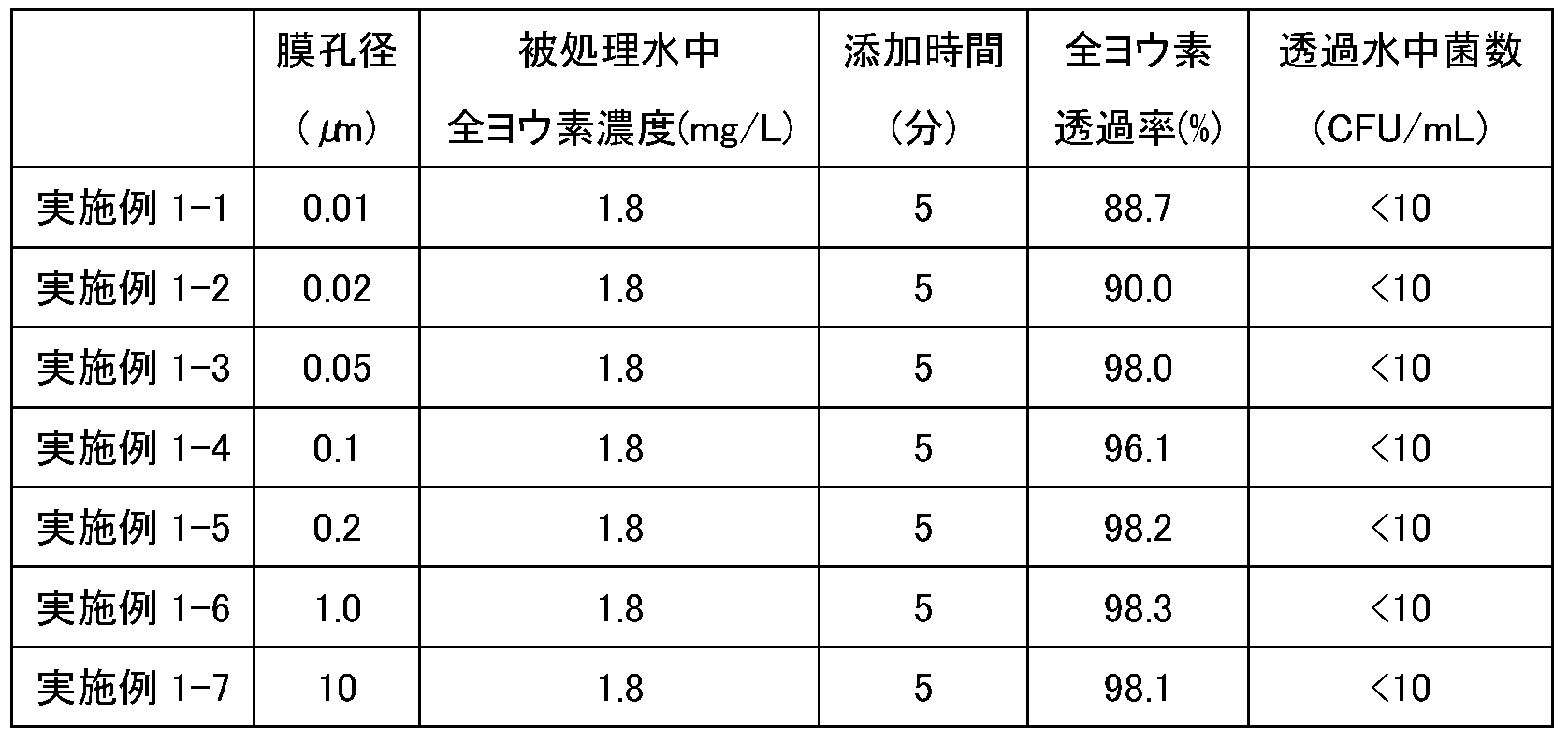
除濁膜の被処理水中の全ヨウ素濃度を1.8mg/Lとしてヨウ素系酸化剤を5分間添加し、透過水の全ヨウ素濃度を測定した結果、全ヨウ素の透過率はいずれも88%以上であった。透過水中の菌数は全てにおいて<10に減少した。実施例1-1~1-7における全ヨウ素CT値は0.15mg/L・hであった。また、さらにヨウ素系酸化剤を5分間添加し続けた結果(計10分間通水であり、全ヨウ素CT値は0.3mg/L・h)、いずれの膜においても全ヨウ素の透過率は96%以上であった。
<実施例2、参考例1>
[全ヨウ素CT値の検討]
図1に示す水処理装置を用いて、(被処理水中の全ヨウ素(mg/L))×(ヨウ素系酸化剤の添加時間(h))で表される全ヨウ素CT値(mg/L・h)を変えて処理を行った。結果を表3に示す。
[全ヨウ素CT値の検討]
図1に示す水処理装置を用いて、(被処理水中の全ヨウ素(mg/L))×(ヨウ素系酸化剤の添加時間(h))で表される全ヨウ素CT値(mg/L・h)を変えて処理を行った。結果を表3に示す。
(試験条件)
試験水:相模原井水(脱塩素処理、菌数2×10³CFU/mL)
薬剤:ヨウ素系酸化剤(3)
pH:7.0
逆浸透膜:ES20、ESPA2、LFC3、TML10D
試験水:相模原井水(脱塩素処理、菌数2×10³CFU/mL)
薬剤:ヨウ素系酸化剤(3)
pH:7.0
逆浸透膜:ES20、ESPA2、LFC3、TML10D
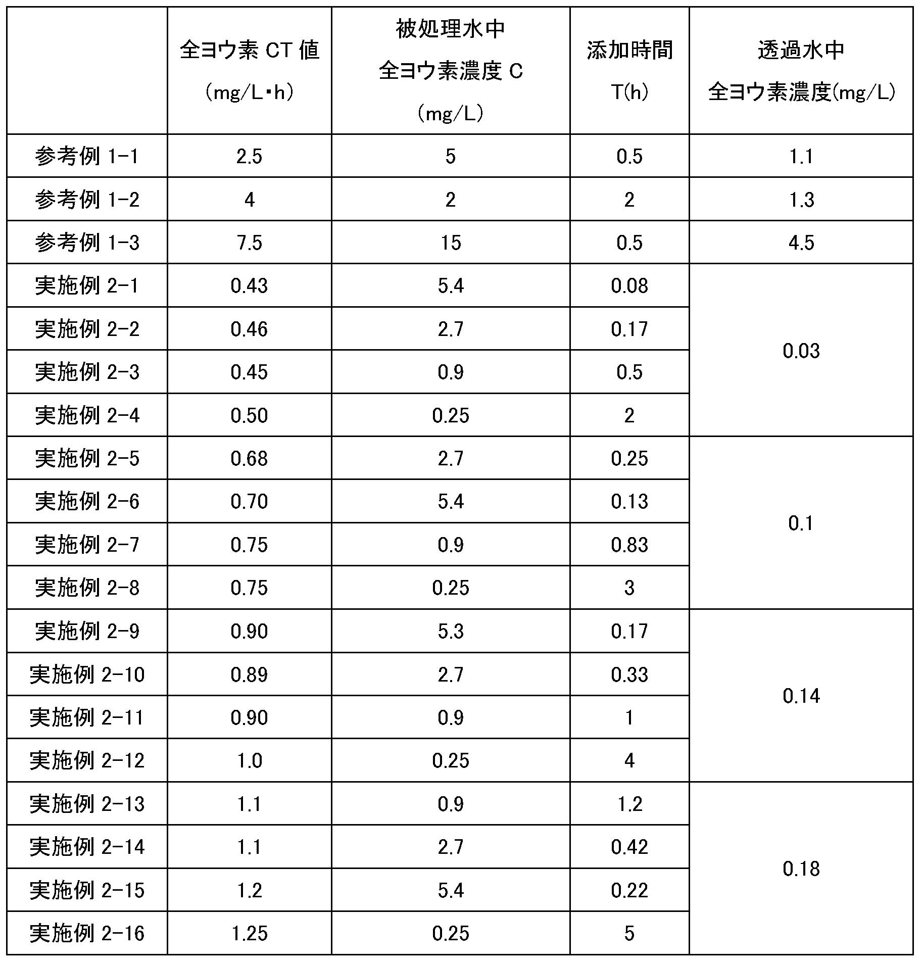
いずれの被処理水中の全ヨウ素濃度であっても透過水の菌数は<10に減少した。簡易な方法で分離膜と逆浸透膜の両方においてスライムが発生することを抑制することができた。なお、参考例1では、高いCT値で通水したことによって透過水中に全ヨウ素濃度が高く検出された。実施例では、透過水中の全ヨウ素濃度を抑制することができた。逆浸透膜のCT値の違いによる全ヨウ素透過率の違いはヨウ素の吸着性の高さと高分子膜であることに由来すると考えられる。ヨウ素は吸着性が高く、特に高分子物質には吸着しやすいことがよく知られており、同様の機構で高分子膜にヨウ素が吸着し、吸着量に応じて透過量が変わると考えられ、吸着量は被処理水中の全ヨウ素濃度と添加時間によって決まることが本発明者らによって明らかにされた。さらに、後述する強アニオン交換樹脂による除去において非荷電のヨウ素が効果的に除去されることを確認しており、ポリアミド系高分子であることによって吸着機構がより効果的に機能すると考えられる。吸着したヨウ素はあるCT値を超えると透過側に検出されるようになり、そのCT値未満で薬剤の添加を停止し、無添加期間を有することによって無添加期間中にヨウ素は濃縮水側に排出される。
[逆浸透膜のスライム抑制試験]
<実験例1、比較実験例1,2>
以下の方法で、逆浸透膜のスライム抑制効果を確認する試験を行った。
<実験例1、比較実験例1,2>
以下の方法で、逆浸透膜のスライム抑制効果を確認する試験を行った。
(試験条件)
・試験水:相模原井水(脱塩素処理、菌数2×10³CFU/mL)に酢酸を1mg/L添加。
・水温:20±2℃
・pH:7.1±1
・逆浸透膜:4インチ逆浸透膜エレメント ESPA2(日東電工製)
・薬剤:比較実験例1では、スライム抑制剤を添加せず、比較実験例2では、下記安定化次亜臭素酸組成物を被処理水中の全塩素濃度が0.9mg/Lとなるように添加し、実験例1では、表1に示す配合組成(質量%)でヨウ素系酸化剤(3)と同様の方法によって調製したヨウ素系酸化剤(7)を被処理水中の全塩素濃度が0.25mg/Lとなるように添加した。
・添加方法:添加期間を180分、無添加期間を1260分に設定し、添加期間と無添加期間を繰り返して運転を実施
・試験水:相模原井水(脱塩素処理、菌数2×10³CFU/mL)に酢酸を1mg/L添加。
・水温:20±2℃
・pH:7.1±1
・逆浸透膜:4インチ逆浸透膜エレメント ESPA2(日東電工製)
・薬剤:比較実験例1では、スライム抑制剤を添加せず、比較実験例2では、下記安定化次亜臭素酸組成物を被処理水中の全塩素濃度が0.9mg/Lとなるように添加し、実験例1では、表1に示す配合組成(質量%)でヨウ素系酸化剤(3)と同様の方法によって調製したヨウ素系酸化剤(7)を被処理水中の全塩素濃度が0.25mg/Lとなるように添加した。
・添加方法:添加期間を180分、無添加期間を1260分に設定し、添加期間と無添加期間を繰り返して運転を実施
逆浸透膜への給水に酢酸を添加して試験水とし、スライムの生成を促進させる試験を実施した。酢酸およびスライム抑制剤添加開始時間を0時間とし、添加以降の差圧の上昇値を得た。結果を図6に示す。
比較実験例1では、試験水にスライム抑制剤を添加せずに逆浸透膜を運転したところ、酢酸添加開始から約80時間後から差圧が大きく上昇し、スライム形成によるバイオファウリングが生じたことがわかった。比較実験例2では、酢酸およびスライム抑制剤添加開始から約150時間後から徐々に差圧が上昇した。実験例1では、大きな差圧上昇は確認されず、十分なスライム抑制効果を得られることを示し、「(1-(透過水導電率/供給水導電率))×100」として求められる逆浸透膜の排除率(%)は初期値が98.5%であり、試験終了後は98.5%であり、低下は見られなかった。
[濃縮水残留全塩素と通水差圧との関係]
<実験例2、比較実験例3>
以下の方法で、濃縮水残留全塩素と通水差圧との関係を確認する試験を行った。結果を表4に示す。
<実験例2、比較実験例3>
以下の方法で、濃縮水残留全塩素と通水差圧との関係を確認する試験を行った。結果を表4に示す。
(試験条件)
・試験水:相模原井水(脱塩素処理、菌数2×10³CFU/mL)に酢酸を1mg/L添加。
・水温:20±2℃
・pH:7.1±1
・逆浸透膜:4インチ逆浸透膜エレメント ESPA2(日東電工製)
・薬剤:比較実験例3では、スライム抑制剤を添加せず、実験例2ではヨウ素系酸化剤(7)を用いた。
・添加方法:添加期間を180分、無添加期間を1260分に設定した運転
・薬剤濃度:添加期間中、浸透膜導入直前の全塩素濃度として0.25mg/L
・濃縮水中残留全塩素濃度の測定:添加開始後約60分経過後の測定値(mg/L as Cl2)
・試験水:相模原井水(脱塩素処理、菌数2×10³CFU/mL)に酢酸を1mg/L添加。
・水温:20±2℃
・pH:7.1±1
・逆浸透膜:4インチ逆浸透膜エレメント ESPA2(日東電工製)
・薬剤:比較実験例3では、スライム抑制剤を添加せず、実験例2ではヨウ素系酸化剤(7)を用いた。
・添加方法:添加期間を180分、無添加期間を1260分に設定した運転
・薬剤濃度:添加期間中、浸透膜導入直前の全塩素濃度として0.25mg/L
・濃縮水中残留全塩素濃度の測定:添加開始後約60分経過後の測定値(mg/L as Cl2)

比較実験例3では、スライム抑制剤を添加せず、濃縮水中残留全塩素濃度を0mg/Lとして運転したところ、通水差圧の初期値からの増加は1kPaであり、スライム形成による差圧上昇が生じたことがわかる。実験例2-1,2-2では、濃縮水中残留全塩素濃度をそれぞれ0.05mg/L、0.1mg/Lとして運転したところ、通水差圧の初期値からの上昇はそれぞれ0.5、0.1kPaであり、スライム形成による差圧上昇を抑制した。実験例2-3では、濃縮水中残留全塩素濃度を0.2mg/Lとして運転したところ、通水差圧の初期値からの増加はほとんど無く、スライム形成による差圧上昇を効果的に抑制した。濃縮水中残留全塩素濃度を0.05mg/L以上を維持し、好ましくは0.1mg/L以上を維持して運転管理を行うことでスライム形成を抑制しつつ、安定的な運転を継続できると考えられる。
<実験例3>
以下の方法で、ヨウ素の透過を確認する試験を行った。
以下の方法で、ヨウ素の透過を確認する試験を行った。
(試験条件)
・試験水:相模原井水(脱塩素処理水)
・試験装置:逆浸透膜エレメント試験装置
・薬剤:表1に示す配合組成(質量%)でヨウ素系酸化剤(3)と同様の方法によってヨウ素に対するヨウ化物のモル比(ヨウ化物/ヨウ素)がそれぞれ1.5,2,3となるようにヨウ素とヨウ化カリウムを混合して調製したヨウ素系酸化剤(7),(2),(1)を用いた。
・試験水:相模原井水(脱塩素処理水)
・試験装置:逆浸透膜エレメント試験装置
・薬剤:表1に示す配合組成(質量%)でヨウ素系酸化剤(3)と同様の方法によってヨウ素に対するヨウ化物のモル比(ヨウ化物/ヨウ素)がそれぞれ1.5,2,3となるようにヨウ素とヨウ化カリウムを混合して調製したヨウ素系酸化剤(7),(2),(1)を用いた。
(総ヨウ素原子の測定)
総ヨウ素原子はICP-MS(PerkinElmer製、ELAN DRC-e ICP質量分析装置)を用いて測定した。サンプル水に十分な量のチオ硫酸ナトリウムを添加し、全てのヨウ素を還元し、アンモニア水を用いてpH9~10とすることによってイオンの安定化を図ったうえで測定を実施した。検量線はヨウ素酸カリウムを用いて作成した。
総ヨウ素原子はICP-MS(PerkinElmer製、ELAN DRC-e ICP質量分析装置)を用いて測定した。サンプル水に十分な量のチオ硫酸ナトリウムを添加し、全てのヨウ素を還元し、アンモニア水を用いてpH9~10とすることによってイオンの安定化を図ったうえで測定を実施した。検量線はヨウ素酸カリウムを用いて作成した。
逆浸透膜の被処理水のサンプルの総ヨウ素原子濃度を測定し、添加時間を乗じることで総ヨウ素CT値とした。
総ヨウ素CT値(mg/L・min)=(被処理水中総ヨウ素原子濃度(mg/L))×(添加時間(min))
総ヨウ素CT値(mg/L・min)=(被処理水中総ヨウ素原子濃度(mg/L))×(添加時間(min))
実験例3-1,3-2,3-3では、ヨウ素系酸化剤(7),(2),(1)をそれぞれ総ヨウ素CT値として20(mg/L・min)となるように連続的に添加したところ、透過量はそれぞれ156μg/L、194μg/L、224μg/Lであった。結果を図7に示す。
実験例3-4,3-5,3-6では、ヨウ素系酸化剤(7),(2),(1)をそれぞれ総ヨウ素CT値として50(mg/L・min)となるように連続的に添加したところ、透過量はそれぞれ252μg/L、310μg/L、336μg/Lであった。結果を図8に示す。
総ヨウ素CT値が20(mg/L・min)および50(mg/L・min)のいずれの場合もヨウ素に対するヨウ化物のモル比が低くなるにつれて透過するヨウ素濃度が低くなっていることがわかる。ヨウ素の透過を抑制するためにはヨウ素に対するヨウ化物のモル比を低くすることが有効であることがわかる。
[全ヨウ素収率、保存安定性]
<実験例4>
表1に示す配合組成(質量%)でヨウ素系酸化剤(3)と同様の方法によって調製した。それぞれ[KI]/[I2]=3、2、1.9、1.8、1.7、1.6、1.5、1.4、1.3、1.2、1.1、1として製剤した。全ヨウ素収率を表1に示す。また、室温(25℃)保管、50℃保管で、30日後、60日後、90日後の有効成分保持率(%)を測定し、保存安定性を評価した。
<実験例4>
表1に示す配合組成(質量%)でヨウ素系酸化剤(3)と同様の方法によって調製した。それぞれ[KI]/[I2]=3、2、1.9、1.8、1.7、1.6、1.5、1.4、1.3、1.2、1.1、1として製剤した。全ヨウ素収率を表1に示す。また、室温(25℃)保管、50℃保管で、30日後、60日後、90日後の有効成分保持率(%)を測定し、保存安定性を評価した。
ヨウ素系酸化剤(1)~(4)では全ヨウ素収率は100%であったが、ヨウ素系酸化剤(5),(6)では94%、93%、ヨウ素系酸化剤(7)では92%となった。全ヨウ素収率が高い方がよいことは想像に容易く、90%以上であるほうがよく、100%であることが最もよい。ヨウ素の透過を抑制し、高い全ヨウ素収率を得るためにはヨウ素に対するヨウ化物のモル比を1.8とすることが最も望ましいことがわかる。また、保存安定性は全てのヨウ素系酸化剤で非常に高く、室温(25℃)保管90日後の有効成分保持率は99%であり、50℃保管90日後の有効成分保持率は99%であった。
[間欠添加運転時の全塩素透過率]
<実験例5>
以下の方法で、間欠添加運転時の全塩素透過率を確認する試験を行った。結果を図9に示す。
<実験例5>
以下の方法で、間欠添加運転時の全塩素透過率を確認する試験を行った。結果を図9に示す。
(試験条件)
・試験水:相模原井水(脱塩素処理、菌数2×10³CFU/mL)に酢酸を1mg/L添加。
・水温:18±2℃
・pH:7.1±1
・逆浸透膜:4インチ逆浸透膜エレメント ESPA2(日東電工製)
・薬剤:実験例5ではヨウ素系酸化剤(3)を用いた。
・添加方法:添加期間を20分、無添加期間を460分に設定し、添加期間と無添加期間を繰り返して運転を実施
・試験水:相模原井水(脱塩素処理、菌数2×10³CFU/mL)に酢酸を1mg/L添加。
・水温:18±2℃
・pH:7.1±1
・逆浸透膜:4インチ逆浸透膜エレメント ESPA2(日東電工製)
・薬剤:実験例5ではヨウ素系酸化剤(3)を用いた。
・添加方法:添加期間を20分、無添加期間を460分に設定し、添加期間と無添加期間を繰り返して運転を実施
実験例の通り、間欠的な添加によって十分なスライム抑制効果が得られ、薬品コストの低減および、全ヨウ素の透過量を削減し、ヨウ素に対するヨウ化物のモル比を1.5~3とすることでヨウ素の透過量を抑制し、後段設備への影響を抑制することができた。
<実験例6>
図2の装置を用い、下記の条件で処理を行った。結果を表5に示す。
図2の装置を用い、下記の条件で処理を行った。結果を表5に示す。
(試験条件)
・試験水:相模原井水(脱塩素処理水)
・逆浸透膜:4インチ逆浸透膜エレメント ESPA2(日東電工製)
・ヨウ素除去装置:実験例7では強アニオン交換体(Amberlite IRA-400HG OH型、スチレン・ジビニルベンゼン共重合体・ゲル型、調和平均径 0.55~0.75mm、総交換容量 ≧1.40 eq/L・湿潤樹脂)を用いた。
・薬剤:実験例7ではヨウ素系酸化剤(7)を用いた。
・添加方法:ヨウ素系酸化剤を試験水に添加して得られた処理水をヨウ素除去装置にSV50の条件で通水した。
・試験水:相模原井水(脱塩素処理水)
・逆浸透膜:4インチ逆浸透膜エレメント ESPA2(日東電工製)
・ヨウ素除去装置:実験例7では強アニオン交換体(Amberlite IRA-400HG OH型、スチレン・ジビニルベンゼン共重合体・ゲル型、調和平均径 0.55~0.75mm、総交換容量 ≧1.40 eq/L・湿潤樹脂)を用いた。
・薬剤:実験例7ではヨウ素系酸化剤(7)を用いた。
・添加方法:ヨウ素系酸化剤を試験水に添加して得られた処理水をヨウ素除去装置にSV50の条件で通水した。

実験例6では、ヨウ素除去装置によって処理後の全塩素は0.01mg/Lとなった。強アニオン交換体を用いることによって、ヨウ素系酸化剤に含有されているマイナス荷電のヨウ化物だけでなく非荷電のヨウ素も除去できることを示した。
<実験例7、比較実験例4>
開放系でスターラ―で撹拌することによるヨウ素除去、さらに曝気を加えたヨウ素除去を検討した。結果を図10に示す。
開放系でスターラ―で撹拌することによるヨウ素除去、さらに曝気を加えたヨウ素除去を検討した。結果を図10に示す。
(試験条件)
試験水:純水
薬剤:ヨウ素系酸化剤(3)
試験水温:20℃(室温管理)
保管状態:スターラ―で撹拌(実験例7-1:解放系、実験例7-2:解放系、曝気、比較実験例4:密閉系)
試験水:純水
薬剤:ヨウ素系酸化剤(3)
試験水温:20℃(室温管理)
保管状態:スターラ―で撹拌(実験例7-1:解放系、実験例7-2:解放系、曝気、比較実験例4:密閉系)
開放系で撹拌を行うことによって、全ヨウ素が消失することを確認した。さらに曝気を行うことによってさらに全ヨウ素が消失することを確認した。ヨウ素除去装置としては気液混合系の水処理システムである、冷却塔やスクラバーが適していると考えられる。
[殺菌効果試験]
<実験例8、比較実験例5,6>
以下の方法で、殺菌効果を確認する試験を行った。
<実験例8、比較実験例5,6>
以下の方法で、殺菌効果を確認する試験を行った。
(試験条件)
・試験水:相模原井水(脱塩素処理)にブイヨンを添加し、30℃で約48時間培養し、菌数を107(CFU/mL)とした。
・水温:25℃(室温管理)
・pH:7.0
・薬剤:比較実験例5では、クロロスルファミン酸(下記の方法で調製)を用いて有効塩素濃度を1.0mg/Lに調整し、比較実験例6では、安定化次亜臭素酸化合物(下記の方法で調製)を用いて、全塩素濃度を0.25mg/Lに調整し、実験例8ではヨウ素系酸化剤(3)を用い、全塩素としてそれぞれ0.04mg/L、0.05mg/L、0.1mg/L(全ヨウ素として0.14mg/L、0.18mg/L、0.36mg/L)となるように添加した。
・試験水:相模原井水(脱塩素処理)にブイヨンを添加し、30℃で約48時間培養し、菌数を107(CFU/mL)とした。
・水温:25℃(室温管理)
・pH:7.0
・薬剤:比較実験例5では、クロロスルファミン酸(下記の方法で調製)を用いて有効塩素濃度を1.0mg/Lに調整し、比較実験例6では、安定化次亜臭素酸化合物(下記の方法で調製)を用いて、全塩素濃度を0.25mg/Lに調整し、実験例8ではヨウ素系酸化剤(3)を用い、全塩素としてそれぞれ0.04mg/L、0.05mg/L、0.1mg/L(全ヨウ素として0.14mg/L、0.18mg/L、0.36mg/L)となるように添加した。
(クロロスルファミン酸の調製)
12%次亜塩素酸ナトリウム水溶液:50質量%、スルファミン酸:10質量%、水酸化ナトリウム:10質量%、水:残分を混合して、組成物を調製した。組成物のpHは14、全塩素濃度は6質量%であった。
12%次亜塩素酸ナトリウム水溶液:50質量%、スルファミン酸:10質量%、水酸化ナトリウム:10質量%、水:残分を混合して、組成物を調製した。組成物のpHは14、全塩素濃度は6質量%であった。
(安定化次亜臭素酸組成物の調製)
窒素雰囲気下で、液体臭素:16.9質量%(wt%)、スルファミン酸:10.7質量%、水酸化ナトリウム:12.9質量%、水酸化カリウム:3.94質量%、水:残分を混合して、安定化次亜臭素酸組成物を調製した。安定化次亜臭素酸組成物のpHは14、全塩素濃度は7.5質量%であった。全塩素濃度は、HACH社の多項目水質分析計DR/3900を用いて、全塩素測定法(DPD(ジエチル-p-フェニレンジアミン)法)により測定した値(mg/L asCl2)である。安定化次亜臭素酸組成物の詳細な調製方法は以下の通りである。
窒素雰囲気下で、液体臭素:16.9質量%(wt%)、スルファミン酸:10.7質量%、水酸化ナトリウム:12.9質量%、水酸化カリウム:3.94質量%、水:残分を混合して、安定化次亜臭素酸組成物を調製した。安定化次亜臭素酸組成物のpHは14、全塩素濃度は7.5質量%であった。全塩素濃度は、HACH社の多項目水質分析計DR/3900を用いて、全塩素測定法(DPD(ジエチル-p-フェニレンジアミン)法)により測定した値(mg/L asCl2)である。安定化次亜臭素酸組成物の詳細な調製方法は以下の通りである。
反応容器内の酸素濃度が1%に維持されるように、窒素ガスの流量をマスフローコントローラでコントロールしながら連続注入で封入した2Lの4つ口フラスコに1436gの水、361gの水酸化ナトリウムを加え混合し、次いで300gのスルファミン酸を加え混合した後、反応液の温度が0~15℃になるように冷却を維持しながら、473gの液体臭素を加え、さらに48%水酸化カリウム溶液230gを加え、組成物全体の量に対する質量比でスルファミン酸10.7%、臭素16.9%、臭素の当量に対するスルファミン酸の当量比が1.04である、目的の安定化次亜臭素酸組成物を得た。生じた溶液のpHは、ガラス電極法にて測定したところ、14であった。生じた溶液の臭素含有率は、臭素をヨウ化カリウムによりヨウ素に転換後、チオ硫酸ナトリウムを用いて酸化還元滴定する方法により測定したところ16.9%であり、理論含有率(16.9%)の100.0%であった。また、臭素反応の際の反応容器内の酸素濃度は、株式会社ジコー製の「酸素モニタJKO-02 LJDII」を用いて測定した。なお、臭素酸濃度は5mg/kg未満であった。
なお、pHの測定は、以下の条件で行った。
電極タイプ:ガラス電極式
pH測定計:東亜ディーケーケー社製、HM-42X型
電極の校正:関東化学社製フタル酸塩pH(4.01)標準液(第2種)、中性リン酸塩pH(6.86)標準液(第2種)、同社製ホウ酸塩pH(9.18)標準液(第2種)の2点校正で行った
測定温度:25℃
測定値:測定液に電極を浸漬し、安定後の値を測定値とし、3回測定の平均値
なお、pHの測定は、以下の条件で行った。
電極タイプ:ガラス電極式
pH測定計:東亜ディーケーケー社製、HM-42X型
電極の校正:関東化学社製フタル酸塩pH(4.01)標準液(第2種)、中性リン酸塩pH(6.86)標準液(第2種)、同社製ホウ酸塩pH(9.18)標準液(第2種)の2点校正で行った
測定温度:25℃
測定値:測定液に電極を浸漬し、安定後の値を測定値とし、3回測定の平均値
薬剤添加前の試験水の菌数を測定し、試験水に薬剤を添加し、10分後に菌数測定を実施して殺菌力を試験した。菌数は、サンアイバイオチェッカーTTC(三愛石油製)を用いて測定した。結果を図11に示す。
比較実験例5では、クロロスルファミン酸を用いて試験を行い、殺菌効果はほとんど得られなかった。比較実験例6では、安定化次亜臭素酸組成物を用いて試験を行い、菌数は3×10⁶に減少した。実験例8-1,8-2,8-3では、ヨウ素系酸化剤を全塩素としてそれぞれ0.04mg/L、0.05mg/L、0.1mg/Lとなるように添加したところ、菌数はそれぞれ3×104、1×103、0に減少し、高い殺菌効果を示した。極めて短い10分間の接触時間であっても強い殺菌効果を示したことで、薬剤の添加時間を短くした間欠添加が有効である可能性が示された。
以上のように、分離膜とその後段の逆浸透膜とを用いる水処理において、実施例のように分離膜にヨウ素系酸化剤を添加する簡易な方法で、分離膜と逆浸透膜の両方においてスライムが発生することを抑制することができた。
1,2,3 水処理装置、4,5 水処理システム、10 被処理水槽、12、64 ろ過処理装置、14 逆浸透膜処理装置、16 被処理水配管、18 被処理水供給配管、20,72 ろ過処理水配管、22,32 透過水配管、24,34 濃縮水配管、26,54,76 ヨウ素系酸化剤添加配管、27,29 配管、28 ヨウ素除去装置、30,84 処理水配管、31 第2逆浸透膜処理装置、36 生物処理装置、38 生物処理水槽、40,66 原水配管、42 生物処理水配管、50 生物処理システム、60 砂ろ過装置、62 ろ過水槽、68 ろ過水配管、70 ろ過水供給配管、74 還元剤添加配管、78 イオン除去装置、80 膜ろ過装置、82 イオン除去処理水配管。
Claims (13)
- 被処理水にヨウ素系酸化剤を添加するヨウ素系酸化剤添加工程と、
前記ヨウ素系酸化剤添加工程で得られた被処理水を分離膜でろ過処理するろ過処理工程と、
前記ろ過処理工程で得られたろ過処理水を逆浸透膜で透過水と濃縮水とに分離する逆浸透膜処理工程と、
を含むことを特徴とする水処理方法。 - 請求項1に記載の水処理方法であって、
前記ヨウ素系酸化剤は、水、ヨウ素およびヨウ化物を含むことを特徴とする水処理方法。 - 請求項1または2に記載の水処理方法であって、
前記ヨウ素系酸化剤添加工程において、(前記被処理水中の全ヨウ素(mg/L))×(前記ヨウ素系酸化剤の添加時間(h))で表される全ヨウ素CT値(mg/L・h)が、1.25(mg/L・h)以下であることを特徴とする水処理方法。 - 請求項1~3のいずれか1項に記載の水処理方法であって、
前記ヨウ素系酸化剤添加工程において、
前記被処理水にヨウ素系酸化剤を添加する添加期間と、
前記被処理水にヨウ素系酸化剤を添加しない無添加期間と、
を設ける間欠添加を行うことを特徴とする水処理方法。 - 請求項4に記載の水処理方法であって、
前記添加期間が連続して10秒以上3時間以下であり、前記無添加期間が連続して5秒以上48時間未満であることを特徴とする水処理方法。 - 請求項1~5のいずれか1項に記載の水処理方法であって、
前記分離膜の膜孔径が、0.01μm以上であることを特徴とする水処理方法。 - 請求項1~6のいずれか1項に記載の水処理方法であって、
前記透過水中のヨウ素成分を除去するヨウ素除去工程をさらに含むことを特徴とする水処理方法。 - 請求項7に記載の水処理方法であって、
前記ヨウ素除去工程において、活性炭およびアニオン交換体のうち少なくとも1つを用いることを特徴とする水処理方法。 - 水とヨウ素とヨウ化物とを含むことを特徴とする膜用のスライム抑制剤。
- 請求項9に記載の膜用のスライム抑制剤であって、
pHが、3以上9以下であることを特徴とする膜用のスライム抑制剤。 - 請求項9または10に記載の膜用のスライム抑制剤であって、
全ヨウ素が、3質量%以上であることを特徴とする膜用のスライム抑制剤。 - 請求項9~11のいずれか1項に記載の膜用のスライム抑制剤であって、
前記ヨウ素に対する前記ヨウ化物のモル比は、1~1.9の範囲であることを特徴とする膜用のスライム抑制剤。 - 被処理水にヨウ素系酸化剤を添加するヨウ素系酸化剤添加手段と、
前記ヨウ素系酸化剤添加手段により得られた被処理水を分離膜でろ過処理するろ過処理手段と、
前記ろ過処理手段で得られたろ過処理水を逆浸透膜で透過水と濃縮水とに分離する逆浸透膜処理手段と、
を備えることを特徴とする水処理装置。
Priority Applications (3)
| Application Number | Priority Date | Filing Date | Title |
|---|---|---|---|
| JP2022509326A JP7333865B2 (ja) | 2020-03-24 | 2021-01-27 | 水処理方法および水処理装置 |
| US17/912,702 US20230174399A1 (en) | 2020-03-24 | 2021-01-27 | Water treatment method, water treatment device and slime inhibitor for membranes |
| CN202180021286.XA CN115315413A (zh) | 2020-03-24 | 2021-01-27 | 水处理方法、水处理装置以及膜用的粘泥抑制剂 |
Applications Claiming Priority (2)
| Application Number | Priority Date | Filing Date | Title |
|---|---|---|---|
| JP2020-053019 | 2020-03-24 | ||
| JP2020053019 | 2020-03-24 |
Publications (1)
| Publication Number | Publication Date |
|---|---|
| WO2021192582A1 true WO2021192582A1 (ja) | 2021-09-30 |
Family
ID=77891222
Family Applications (1)
| Application Number | Title | Priority Date | Filing Date |
|---|---|---|---|
| PCT/JP2021/002716 Ceased WO2021192582A1 (ja) | 2020-03-24 | 2021-01-27 | 水処理方法、水処理装置、および膜用のスライム抑制剤 |
Country Status (5)
| Country | Link |
|---|---|
| US (1) | US20230174399A1 (ja) |
| JP (1) | JP7333865B2 (ja) |
| CN (1) | CN115315413A (ja) |
| TW (1) | TWI864244B (ja) |
| WO (1) | WO2021192582A1 (ja) |
Cited By (2)
| Publication number | Priority date | Publication date | Assignee | Title |
|---|---|---|---|---|
| WO2023243244A1 (ja) * | 2022-06-16 | 2023-12-21 | オルガノ株式会社 | 水処理方法、水処理装置、スライム抑制剤、および洗浄方法 |
| WO2024224911A1 (ja) * | 2023-04-27 | 2024-10-31 | オルガノ株式会社 | 水処理方法および水処理装置 |
Citations (4)
| Publication number | Priority date | Publication date | Assignee | Title |
|---|---|---|---|---|
| JPS61257206A (ja) * | 1985-05-04 | 1986-11-14 | ザ ビ−.エフ.グツドリツチ カンパニ− | 逆浸透水精製系中の生物生育を防止する方法 |
| JPH07124559A (ja) * | 1993-11-08 | 1995-05-16 | Toyobo Co Ltd | 海水淡水化プロセスにおける被処理水の殺菌方法 |
| JP2011161435A (ja) * | 2010-01-14 | 2011-08-25 | Toray Ind Inc | 半透膜の性能回復処理方法 |
| JP2020006332A (ja) * | 2018-07-10 | 2020-01-16 | 王子ホールディングス株式会社 | 水処理装置および水処理方法 |
Family Cites Families (8)
| Publication number | Priority date | Publication date | Assignee | Title |
|---|---|---|---|---|
| US3992301A (en) * | 1973-11-19 | 1976-11-16 | Raypak, Inc. | Automatic flushing system for membrane separation machines such as reverse osmosis machines |
| US4278548A (en) * | 1979-08-20 | 1981-07-14 | E. I. Du Pont De Nemours And Company | Control of biological growth in reverse osmosis permeators |
| US5269919A (en) * | 1992-01-17 | 1993-12-14 | Von Medlin Wallace | Self-contained water treatment system |
| US20070227966A1 (en) * | 2006-03-31 | 2007-10-04 | Koo Ja-Young | Composite polyamide reverse osmosis membrane showing high boron rejection and method of producing the same |
| JP6325658B2 (ja) * | 2014-05-08 | 2018-05-16 | オルガノ株式会社 | ろ過処理方法 |
| WO2018084061A1 (ja) * | 2016-11-07 | 2018-05-11 | オルガノ株式会社 | 逆浸透膜処理方法および逆浸透膜処理システム |
| JP6807219B2 (ja) * | 2016-11-18 | 2021-01-06 | オルガノ株式会社 | 逆浸透膜処理システムおよび逆浸透膜処理方法 |
| US20190344221A1 (en) * | 2018-05-08 | 2019-11-14 | Michael Smith | System and method for preventing membrane fouling in reverse osmosis purification systems utilizing hydrodynamic cavitation |
-
2021
- 2021-01-27 WO PCT/JP2021/002716 patent/WO2021192582A1/ja not_active Ceased
- 2021-01-27 CN CN202180021286.XA patent/CN115315413A/zh active Pending
- 2021-01-27 US US17/912,702 patent/US20230174399A1/en active Pending
- 2021-01-27 JP JP2022509326A patent/JP7333865B2/ja active Active
- 2021-03-05 TW TW110107804A patent/TWI864244B/zh active
Patent Citations (4)
| Publication number | Priority date | Publication date | Assignee | Title |
|---|---|---|---|---|
| JPS61257206A (ja) * | 1985-05-04 | 1986-11-14 | ザ ビ−.エフ.グツドリツチ カンパニ− | 逆浸透水精製系中の生物生育を防止する方法 |
| JPH07124559A (ja) * | 1993-11-08 | 1995-05-16 | Toyobo Co Ltd | 海水淡水化プロセスにおける被処理水の殺菌方法 |
| JP2011161435A (ja) * | 2010-01-14 | 2011-08-25 | Toray Ind Inc | 半透膜の性能回復処理方法 |
| JP2020006332A (ja) * | 2018-07-10 | 2020-01-16 | 王子ホールディングス株式会社 | 水処理装置および水処理方法 |
Non-Patent Citations (2)
| Title |
|---|
| BETTINGER, G. E.: "Controlling biological activity in a surface water reverse osmosis plant.", DESALINATION, vol. 38, no. 1, 1981, pages 419 - 424, XP055863280 * |
| NAAKTGEBOREN A.J., SNIJDERS G.J., GONS J.: "Characterization of a new reverse osmosis composite membrane for industrial application", DESALINATION, vol. 68, no. 2-3, 1 March 1988 (1988-03-01), NL , pages 223 - 242, XP055863275, ISSN: 0011-9164, DOI: 10.1016/0011-9164(88)80057-2 * |
Cited By (6)
| Publication number | Priority date | Publication date | Assignee | Title |
|---|---|---|---|---|
| WO2023243244A1 (ja) * | 2022-06-16 | 2023-12-21 | オルガノ株式会社 | 水処理方法、水処理装置、スライム抑制剤、および洗浄方法 |
| JP2023183453A (ja) * | 2022-06-16 | 2023-12-28 | オルガノ株式会社 | 水処理方法、水処理装置、スライム抑制剤、および洗浄方法 |
| CN119365421A (zh) * | 2022-06-16 | 2025-01-24 | 奥加诺株式会社 | 水处理方法、水处理装置、粘泥抑制剂以及清洗方法 |
| KR20250016292A (ko) | 2022-06-16 | 2025-02-03 | 오르가노 코포레이션 | 수처리방법, 수처리장치, 슬라임 억제제 및 세정 방법 |
| WO2024224911A1 (ja) * | 2023-04-27 | 2024-10-31 | オルガノ株式会社 | 水処理方法および水処理装置 |
| KR20250168474A (ko) | 2023-04-27 | 2025-12-02 | 오르가노 코포레이션 | 수처리방법 및 수처리장치 |
Also Published As
| Publication number | Publication date |
|---|---|
| US20230174399A1 (en) | 2023-06-08 |
| CN115315413A (zh) | 2022-11-08 |
| JPWO2021192582A1 (ja) | 2021-09-30 |
| JP7333865B2 (ja) | 2023-08-25 |
| TW202138307A (zh) | 2021-10-16 |
| TWI864244B (zh) | 2024-12-01 |
Similar Documents
| Publication | Publication Date | Title |
|---|---|---|
| TWI835878B (zh) | 水處理裝置及水處理方法 | |
| JP6970516B2 (ja) | 逆浸透膜を用いる水処理方法 | |
| JP6622424B2 (ja) | 逆浸透膜処理方法および逆浸透膜処理システム | |
| TW201603876A (zh) | 過濾處理系統及過濾處理方法 | |
| JP7367181B2 (ja) | 水回収システムおよび水回収方法 | |
| JP7333865B2 (ja) | 水処理方法および水処理装置 | |
| WO2018078988A1 (ja) | 逆浸透膜を用いる水処理方法および水処理装置 | |
| JP7013141B2 (ja) | 逆浸透膜を用いる水処理方法 | |
| JP3641854B2 (ja) | 逆浸透膜分離方法および逆浸透膜分離装置 | |
| JP2020058972A (ja) | 正浸透膜処理方法、正浸透膜処理システム、水処理方法、および水処理システム | |
| JP7050414B2 (ja) | 逆浸透膜を用いる水処理方法 | |
| JP2022016897A (ja) | 水回収方法および水回収装置 | |
| JP7498580B2 (ja) | 殺菌剤、殺菌剤の製造方法、殺菌方法、分離膜用スライム抑制剤、および分離膜のスライム抑制方法 | |
| JP7141919B2 (ja) | 逆浸透膜処理方法、逆浸透膜処理システム、水処理方法、および水処理システム | |
| JP3312483B2 (ja) | 逆浸透処理方法および造水方法 | |
| JP7492876B2 (ja) | 水処理方法および水処理装置 | |
| JP7052461B2 (ja) | 電気再生式脱イオン装置の運転制御方法および水処理装置 | |
| JPH0957067A (ja) | 逆浸透膜分離方法およびその装置 | |
| TW202448808A (zh) | 水處理方法及水處理裝置 | |
| TW201940225A (zh) | 水系統的氧化還原電位監測及/或控制方法、水處理方法、逆滲透膜處理方法、水系統的氧化還原電位的監測及/或控制裝置以及水處理裝置 | |
| JP2025025902A (ja) | 純水用水の製造方法及び製造装置、純水製造方法及び純水製造システム | |
| CN116322947A (zh) | 超纯水制造系统及超纯水制造方法 |
Legal Events
| Date | Code | Title | Description |
|---|---|---|---|
| 121 | Ep: the epo has been informed by wipo that ep was designated in this application |
Ref document number: 21775076 Country of ref document: EP Kind code of ref document: A1 |
|
| ENP | Entry into the national phase |
Ref document number: 2022509326 Country of ref document: JP Kind code of ref document: A |
|
| NENP | Non-entry into the national phase |
Ref country code: DE |
|
| 122 | Ep: pct application non-entry in european phase |
Ref document number: 21775076 Country of ref document: EP Kind code of ref document: A1 |