WO2021187542A1 - 検出体および検出システム - Google Patents
検出体および検出システム Download PDFInfo
- Publication number
- WO2021187542A1 WO2021187542A1 PCT/JP2021/010929 JP2021010929W WO2021187542A1 WO 2021187542 A1 WO2021187542 A1 WO 2021187542A1 JP 2021010929 W JP2021010929 W JP 2021010929W WO 2021187542 A1 WO2021187542 A1 WO 2021187542A1
- Authority
- WO
- WIPO (PCT)
- Prior art keywords
- strain
- detector
- detection
- detection sensor
- fastening
- Prior art date
- Legal status (The legal status is an assumption and is not a legal conclusion. Google has not performed a legal analysis and makes no representation as to the accuracy of the status listed.)
- Ceased
Links
Images


Classifications
-
- G—PHYSICS
- G01—MEASURING; TESTING
- G01L—MEASURING FORCE, STRESS, TORQUE, WORK, MECHANICAL POWER, MECHANICAL EFFICIENCY, OR FLUID PRESSURE
- G01L5/00—Apparatus for, or methods of, measuring force, work, mechanical power, or torque, specially adapted for specific purposes
- G01L5/24—Apparatus for, or methods of, measuring force, work, mechanical power, or torque, specially adapted for specific purposes for determining value of torque or twisting moment for tightening a nut or other member which is similarly stressed
-
- G—PHYSICS
- G01—MEASURING; TESTING
- G01L—MEASURING FORCE, STRESS, TORQUE, WORK, MECHANICAL POWER, MECHANICAL EFFICIENCY, OR FLUID PRESSURE
- G01L5/00—Apparatus for, or methods of, measuring force, work, mechanical power, or torque, specially adapted for specific purposes
- G01L5/16—Apparatus for, or methods of, measuring force, work, mechanical power, or torque, specially adapted for specific purposes for measuring several components of force
- G01L5/161—Apparatus for, or methods of, measuring force, work, mechanical power, or torque, specially adapted for specific purposes for measuring several components of force using variations in ohmic resistance
- G01L5/1627—Apparatus for, or methods of, measuring force, work, mechanical power, or torque, specially adapted for specific purposes for measuring several components of force using variations in ohmic resistance of strain gauges
-
- G—PHYSICS
- G01—MEASURING; TESTING
- G01L—MEASURING FORCE, STRESS, TORQUE, WORK, MECHANICAL POWER, MECHANICAL EFFICIENCY, OR FLUID PRESSURE
- G01L1/00—Measuring force or stress, in general
- G01L1/20—Measuring force or stress, in general by measuring variations in ohmic resistance of solid materials or of electrically-conductive fluids; by making use of electrokinetic cells, i.e. liquid-containing cells wherein an electrical potential is produced or varied upon the application of stress
- G01L1/22—Measuring force or stress, in general by measuring variations in ohmic resistance of solid materials or of electrically-conductive fluids; by making use of electrokinetic cells, i.e. liquid-containing cells wherein an electrical potential is produced or varied upon the application of stress using resistance strain gauges
- G01L1/2206—Special supports with preselected places to mount the resistance strain gauges; Mounting of supports
- G01L1/2231—Special supports with preselected places to mount the resistance strain gauges; Mounting of supports the supports being disc- or ring-shaped, adapted for measuring a force along a single direction
-
- G—PHYSICS
- G01—MEASURING; TESTING
- G01L—MEASURING FORCE, STRESS, TORQUE, WORK, MECHANICAL POWER, MECHANICAL EFFICIENCY, OR FLUID PRESSURE
- G01L1/00—Measuring force or stress, in general
- G01L1/20—Measuring force or stress, in general by measuring variations in ohmic resistance of solid materials or of electrically-conductive fluids; by making use of electrokinetic cells, i.e. liquid-containing cells wherein an electrical potential is produced or varied upon the application of stress
- G01L1/22—Measuring force or stress, in general by measuring variations in ohmic resistance of solid materials or of electrically-conductive fluids; by making use of electrokinetic cells, i.e. liquid-containing cells wherein an electrical potential is produced or varied upon the application of stress using resistance strain gauges
- G01L1/225—Measuring circuits therefor
-
- G—PHYSICS
- G01—MEASURING; TESTING
- G01L—MEASURING FORCE, STRESS, TORQUE, WORK, MECHANICAL POWER, MECHANICAL EFFICIENCY, OR FLUID PRESSURE
- G01L1/00—Measuring force or stress, in general
- G01L1/20—Measuring force or stress, in general by measuring variations in ohmic resistance of solid materials or of electrically-conductive fluids; by making use of electrokinetic cells, i.e. liquid-containing cells wherein an electrical potential is produced or varied upon the application of stress
- G01L1/22—Measuring force or stress, in general by measuring variations in ohmic resistance of solid materials or of electrically-conductive fluids; by making use of electrokinetic cells, i.e. liquid-containing cells wherein an electrical potential is produced or varied upon the application of stress using resistance strain gauges
- G01L1/2287—Measuring force or stress, in general by measuring variations in ohmic resistance of solid materials or of electrically-conductive fluids; by making use of electrokinetic cells, i.e. liquid-containing cells wherein an electrical potential is produced or varied upon the application of stress using resistance strain gauges constructional details of the strain gauges
-
- G—PHYSICS
- G01—MEASURING; TESTING
- G01L—MEASURING FORCE, STRESS, TORQUE, WORK, MECHANICAL POWER, MECHANICAL EFFICIENCY, OR FLUID PRESSURE
- G01L5/00—Apparatus for, or methods of, measuring force, work, mechanical power, or torque, specially adapted for specific purposes
- G01L5/24—Apparatus for, or methods of, measuring force, work, mechanical power, or torque, specially adapted for specific purposes for determining value of torque or twisting moment for tightening a nut or other member which is similarly stressed
- G01L5/243—Apparatus for, or methods of, measuring force, work, mechanical power, or torque, specially adapted for specific purposes for determining value of torque or twisting moment for tightening a nut or other member which is similarly stressed using washers
Definitions
- the present invention relates to detectors and detection systems.
- the looseness of the fastening member can be detected by detecting the strain of the member (distortion body) fixed to the installation surface by the fastening member (for example, bolt, nut, etc.) by the strain sensor provided on the member.
- the fastening member for example, bolt, nut, etc.
- Patent Document 1 discloses a technique for attaching a strain gauge to the outer peripheral surface of a cylindrical body having a flange shape.
- Patent Document 2 discloses a technique for detecting the occurrence of loosening of a bolt by providing a strain gauge in the vicinity of the bolt in a fixed portion of an electric motor.
- one embodiment aims to improve the detection accuracy of the strain of the strain-causing body by the strain gauge installed on the strain-causing body.
- One detection body is a detection body that detects a fastening axial force applied in the axial direction by the fastening means, and is a strain-causing body having a through hole through which a bolt portion of the fastening means is inserted.
- a strain detection sensor for detecting the distortion of the strain body is provided, the strain generator is formed in a block shape and has a flat surface portion on a side surface along the axial direction, and the strain detection sensor is provided on the flat surface portion. ..
- the other detector according to the embodiment is a detector that detects the fastening axial force applied in the axial direction by the fastening means, and is a strain generating body having a through hole through which the bolt portion of the fastening means is inserted.
- a strain detection sensor for detecting the strain of the strain-causing body is provided, and the strain-causing body has a block-shaped base having a through hole and a thin plate-like shape protruding from the outside of the base in a direction intersecting the axial direction.
- the distortion detection sensor is provided on the protruding portion.
- Perspective view showing the appearance of the upper surface side of the detector according to the first embodiment Perspective view showing the appearance of the upper surface side of the detector according to the first embodiment.
- An exploded perspective view of the detector according to the first embodiment The figure which shows the arrangement position of the strain detection element in the detection body which concerns on 1st Embodiment Circuit diagram of a bridge circuit included in the detector according to the first embodiment
- the figure which shows an example of the dimension of each part of the detector which concerns on 1st Embodiment The figure which shows the use example of the detector which concerns on 1st Embodiment
- Perspective view showing the appearance of the upper surface side of the detector according to the second embodiment Perspective view showing the appearance of the upper surface side of the detector according to the second embodiment.
- FIG. 1 An exploded perspective view of the detector according to the second embodiment
- the figure which shows the arrangement position of the strain detection element in the detection body which concerns on 2nd Embodiment Circuit diagram of a bridge circuit included in the detector according to the second embodiment
- the figure which shows the structure of the control circuit included in the detector which concerns on 3rd Embodiment Flow chart showing the work procedure of the detector according to the third embodiment
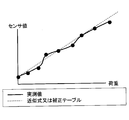
- the figure which shows an example of the input / output characteristic of the detector which concerns on 3rd Embodiment A graph showing a change in resistance value with respect to distortion of the sensor included in the detector according to the third embodiment.
- the figure which shows the 1st modification of the installation position of the sensor in the strain-causing body which concerns on 3rd Embodiment The figure which shows the 2nd modification of the installation position of the sensor in the strain-causing body which concerns on 3rd Embodiment
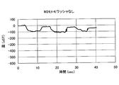
- the figure which shows the evaluation result of the detector which concerns on 3rd Embodiment Exploded view of the fastening structure according to the fourth embodiment The figure which shows the fastening state of the fastening structure which concerns on 4th Embodiment
- the Z-axis direction in the figure (the axial direction of the central axis X described later) is the vertical direction
- the X-axis direction in the figure (the lateral direction of the flat surface portion 16A described later) is the horizontal direction.
- the Y-axis direction (the vertical direction of the flat surface portion 16A described later) is the front-back direction.
- the X-axis direction in the figure and the Y-axis direction in the figure are horizontal directions.
- FIG. 1 is a perspective view showing the appearance of the upper surface side of the detector 10 according to the first embodiment.
- the detector 10 shown in FIG. 1 is a device having a substantially cylindrical shape.
- the detector 10 is installed between the fastening member (bolt or nut) and the fastening member when the fastening member is screwed and fixed to a predetermined mounting surface (for example, a wall surface). It is possible to detect the fastening axial force applied in the axial direction of the central shaft X1 by fastening the fastening member.
- the detector 10 includes a strain generator 12 and a strain detection module 20.
- the strain generating body 12 is a block-shaped member having a substantially cylindrical shape.
- the strain-causing body 12 is formed by preferably using a metal material such as stainless steel.
- a through hole 14 is formed so as to penetrate the strain-causing body 12 in the vertical direction (Z-axis direction) along the central axis X1.
- the through hole 14 is a portion through which the bolt portion of the fastening means 42 (see FIG. 7) is inserted.
- the "bolt part" is a bolt shaft fixed to the mounting surface. That is, when the fastening member is a nut, the fastening means 42 is composed of the nut and a bolt shaft fixed to the mounting surface.
- the fastening member when the fastening member is a bolt, the "bolt part" is the bolt shaft of the bolt. That is, when the fastening member is a bolt, the fastening means 42 is composed of the bolt and a nut fixed to the mounting surface.
- an annular pedestal portion 18 centered on the central axis X1 and surrounding the through hole 14 is formed on the upper surface of the strain generating body 12.
- the pedestal portion 18 is a portion on the upper surface of the strain generating body 12 whose height position is slightly higher than that of the peripheral portion of the pedestal portion 18.
- the upper surface 18A of the pedestal portion 18 functions as a flat receiving portion for receiving the fastening member (bolt or nut).
- a pair of flat surface portions 16A and 16B are formed on the side surface of the strain generating body 12 in the front-rear direction (Y-axis direction) with a through hole 14 sandwiched between them.
- the pair of plane portions 16A and 16B are parallel to each other and both are parallel to the XZ plane.
- the flat surface portion 16A is formed at a position closer to the central axis X1 than the flat surface portion 16B. As a result, the flat surface portion 16A has a larger area than the flat surface portion 16B.
- the pair of flat surface portions 16A and 16B are formed, for example, by cutting out a part of the outer peripheral surface of the strain-causing body 12 before processing having a cylindrical shape in parallel with the XZ plane.
- the strain detection module 20 is provided on the flat surface portion 16A on the side surface of the strain generating body 12.
- the distortion detection module 20 can detect the distortion of the strain generating body 12 and output a distortion detection signal representing the magnitude of the detected distortion by a voltage value to the outside by wireless communication.
- the strain detection module 20 includes a sealing resin 25 that covers the entire strain detection module 20.
- the sealing resin 25 protects the other components and the flat surface portion 16A from rainwater, dirt, etc. by covering the other components of the strain detection module 20 and the entire flat surface portion 16A of the strain generating body 12. do.
- the sealing resin 25 is formed in a shape that follows the outer shape of the strain-causing body 12 so as not to give a sense of discomfort in appearance.
- the present invention is not limited to this, and the outer shape of the sealing resin 25 may be any shape.
- the outer shape of the sealing resin 25 may be a shape naturally formed by potting.
- FIG. 2 is a perspective view showing the appearance of the upper surface side of the detector 10 according to the first embodiment.
- FIG. 3 is an exploded perspective view of the detector 10 according to the first embodiment. However, in FIG. 2, the sealing resin 25 of the strain detection module 20 is shown transparent.
- the strain detection module 20 includes a strain detection sensor 21, a wiring pattern 22, an IC (Integrated Circuit) 23, a communication antenna 24, and a sealing resin 25.
- IC Integrated Circuit
- the strain detection sensor 21 includes a first strain detection element 21A, a second strain detection element 21B, a third strain detection element 21C, and a fourth strain detection element 21D.
- Each of the strain detecting elements 21A to 21D is arranged on the flat surface portion 16A.
- Each of the strain detecting elements 21A to 21D detects the strain of the strain generating body 12.
- a strain resistance element whose resistance value changes according to the amount of strain is used.
- the strain detection elements 21A to 21D constitute a bridge circuit 30 (see FIG. 5). The arrangement positions of the strain detection elements 21A to 21D will be described later with reference to FIG.
- the wiring pattern 22 is a conductive strip-shaped member formed on the flat surface portion 16A, connecting each of the strain detecting elements 21A to 21D and the IC 23, and connecting the communication antenna 24 and the IC 23.
- the wiring pattern 22 is used for transmitting a distortion detection signal between each of the distortion detection elements 21A to 21D and the IC23, and between the communication antenna 24 and the IC23.
- the wiring pattern 22 is formed by using, for example, a thin-film conductor (for example, copper foil).
- the IC23 is an example of a "control circuit".
- the IC 23 is installed on the flat surface portion 16A and controls the operation of the distortion detection module 20.
- the IC 23 acquires a distortion detection signal indicating the magnitude of the distortion of the strain generating body 12 from the bridge circuit 30 composed of the distortion detecting elements 21A to 21D via the wiring pattern 22.
- the IC 23 wirelessly transmits the distortion detection signal acquired from the bridge circuit 30 to an external device using the communication antenna 24.
- the communication antenna 24 is used for transmitting a distortion detection signal.
- the communication antenna 24 includes a radiation surface 24A formed by bending a plurality of thin plate-shaped and strip-shaped conductors in the same plane shape.
- the radial surface 24A is parallel to the flat surface portion 16A and is arranged away from the flat surface portion 16A.
- the communication antenna 24 is provided at each of both ends of the radiating surface 24A and is connected to the wiring pattern 22 formed on the flat surface portion 16A by two legs 24B perpendicular to the radiating surface 24A.
- FIG. 4 is a diagram showing the arrangement positions of the strain detecting elements 21A to 21D in the detection body 10 according to the first embodiment.
- FIG. 4 shows the side surface of the detector 10 when the flat surface portion 16A is viewed in a plan view from the negative side of the Y axis.
- the first strain detecting element 21A and the second strain detecting element 21B sandwich the central axis X1 in the vicinity of the lower end portion (the end portion on the negative side of the Z axis) of the flat surface portion 16A. They are provided side by side in the left-right direction (X-axis direction).
- the first strain detection element 21A is installed on the left side of the central axis X1
- the second strain detection element 21B is installed on the right side of the central axis X1
- the first strain detection element 21A and The second strain detecting element 21B is installed at positions at equal intervals from the central axis X1.
- the first strain detecting element 21A is installed at a position overlapping the left end position of the inner peripheral surface of the through hole 14, and the second strain detecting element 21B is installed at a position overlapping the right end position of the inner peripheral surface of the through hole 14. It is installed in an overlapping position.
- the third strain detecting element 21C and the fourth strain detecting element 21D are located at a position overlapping the central axis X1 in the central portion of the flat surface portion 16A in the vertical direction (Z-axis direction). They are provided side by side in the vertical direction (Z-axis direction).
- the third strain detecting element 21C is arranged on the upper side
- the fourth strain detecting element 21D is arranged on the lower side.
- a third setting position is obtained. This is a position where a larger negative strain (strain in the tensile direction) is generated in each of the strain detection element 21C and the fourth strain detection element 21D.
- strain detection elements 21A to 21D can be installed on the flat surface portion 16A by various installation methods.
- strain detecting elements 21A to 21D may be directly attached to the flat surface portion 16A with an adhesive or the like.
- the strain detection elements 21A to 21D may be formed on the flat surface portion 16A by printing a composite resistor in which the cermet or the binder is a synthetic resin on the flat surface portion 16A. Also in this case, the strain detecting elements 21A to 21D can be easily and surely installed at a predetermined installation position on the flat surface portion 16A. In particular, in this case, in a state where a plurality of strain generating bodies 12 are arranged side by side, printing, drying, and curing of the strain detecting elements 21A to 21D can be collectively performed on the plurality of strain generating bodies 12, so that a plurality of strain detecting elements 12 can be printed, dried, and cured. The strain detecting elements 21A to 21D can be easily and surely installed on the strain generating body 12.
- the strain detection elements 21A to 21D may be attached to the flat surface portion 16A together with the rigid substrate or the flexible substrate in a state of being mounted on the rigid substrate or the flexible substrate. Also in this case, since the installation surface is flat, the strain detection elements 21A to 21D can be easily and surely installed at a predetermined installation position on the flat surface portion 16A.
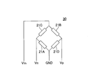
- FIG. 5 is a circuit diagram of a bridge circuit 30 included in the detector 10 according to the first embodiment. As shown in FIG. 5, the bridge circuit 30 includes distortion detecting elements 21A to 21D.
- the resistance values of the strain detecting elements 21C and 21D increase as the fastening axial force of the central axis X1 with respect to the strain generating body 12 in the axial direction increases.
- the resistance values of the strain detecting elements 21A and 21B decrease as the fastening axial force of the central axis X1 with respect to the strain generating body 12 in the axial direction increases.
- the voltage value Vp at the connection point between the strain detecting element 21B and the strain detecting element 21D increases. Further, as the fastening axial force of the central axis X1 with respect to the strain generating body 12 in the axial direction increases, the voltage value Vn at the connection point between the strain detecting element 21A and the strain detecting element 21C becomes smaller.
- the bridge circuit 30 amplifies and outputs the voltage difference between the voltage value Vp and the voltage value Vn by a differential amplifier (not shown). As a result, the bridge circuit 30 can output a distortion detection signal in which the voltage value increases as the fastening axial force of the central axis X1 with respect to the strain generating body 12 in the axial direction increases.
- the tightening torque of the fastening member and the fastening axial force of the central axis X1 with respect to the strain generating body 12 in the axial direction are in a proportional relationship with each other. That is, as the tightening torque of the fastening member increases, the fastening axial force of the central axis X1 with respect to the strain generating body 12 in the axial direction increases. Therefore, the bridge circuit 30 can output a distortion detection signal whose voltage value increases as the tightening torque of the fastening member increases.
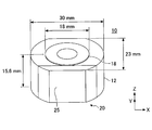
- FIG. 6 is a diagram showing an example of the dimensions of each part of the detector 10 according to the first embodiment.
- FIG. 6 shows an example of the dimensions of each part of the detector 10 when the detector 10 is attached to a bolt shaft having a diameter of 8 mm.
- the lateral width (width in the X-axis direction) of the detector 10 is 30 mm.
- the diameter of the pedestal portion 18 formed on the upper surface of the strain generating body 12 is 18 mm.
- the front-rear width (width in the Y-axis direction) of the detector 10 is 23 mm.
- the vertical width (width in the Z-axis direction) of the detector 10 is 15.6 mm.
- FIG. 7 is a diagram showing a usage example of the detector 10 according to the first embodiment.
- FIG. 7 shows an example in which the flat plate-shaped member to be fastened 43 is screwed and fixed to the mounting surface 41 by the nut 42B.
- the detection body 10 is provided between the nut 42B and the member to be fastened 43.
- a bolt shaft 42A extending upward from the mounting surface 41 penetrates the strained body 12 of the member to be fastened 43 and the detection body 10.
- the end portion (end portion on the negative side of the Z axis) of the bolt shaft 42A is fixed to the mounting surface 41.
- the nut 42B is screwed to the bolt shaft 42A from the tip end portion (the end portion on the positive side of the Z axis) of the bolt shaft 42A.
- the nut 42B, together with the bolt shaft 42A, constitutes the fastening means 42.
- the strain-causing body 12 of the detection body 10 receives the nut 42B on the upper surface 18A of the pedestal portion 18 formed on the upper surface thereof.
- a fastening axial force in the axial direction (Z-axis direction) of the bolt shaft 42A is applied to the strain generating body 12.
- the diameter of the pedestal portion 18 is larger than the maximum dimension (diagonal length) of the nut.
- the strain generating body 12 can more reliably receive the fastening axial force applied from the nut 42B by the upper surface 18A of the pedestal portion 18.
- the strain generating body 12 is distorted according to the tightening torque of the nut 42B.
- the strain generated in the strain generating body 12 is detected by each of the strain detecting elements 21A to 21D (see FIGS. 3 to 5) included in the strain detecting module 20 of the detecting body 10.
- the bridge circuit 30 included in the distortion detection module 20 is based on the distortion detected by each of the distortion detection elements 21A to 21D (that is, the change in the resistance value of each of the distortion detection elements 21A to 21D).
- a distortion detection signal corresponding to the tightening torque of the nut 42B is output to the IC 23 included in the distortion detection module 20.
- the IC 23 outputs the distortion detection signal acquired from the bridge circuit 30 to an external device via wireless communication. For example, an external device can determine the tightened state of the nut 42B based on the voltage value indicated by the strain detection signal acquired from the detection body 10.
- the distortion detection module 20 may generate electric power by the electromotive coil when the tag reader is held over the strain detection module 20, and wirelessly transmit the distortion detection signal to the tag reader using the electric power. good.
- the distortion detection module 20 can be configured not to include a battery and a memory.
- the present invention is not limited to this, and the distortion detection module 20 may be configured to include at least one of a battery and a memory.
- the detection body 10 is the detection body 10 that detects the fastening axial force applied in the direction of the central axis X1 by the fastening means 42, and the bolt portion of the fastening means 42 is inserted through the detector body 10.
- a strain generating body 12 having a through hole 14 and a strain detecting sensor 21 for detecting the strain of the strain generating body 12 are provided, and the strain generating body 12 is formed in a block shape and is formed on a side surface along the central axis X1 direction. It has a flat surface portion 16A, and the strain detection sensor 21 is provided on the flat surface portion 16A.
- the detector 10 according to the first embodiment can install the strain detection sensor 21 on the flat surface portion 16A on the side surface of the strain generating body 12, so that it is easy and reliable with respect to a predetermined installation position on the flat surface portion 16A.
- the strain detection sensor 21 can be installed in the space. Therefore, according to the detector 10 according to the first embodiment, the distortion detection accuracy of the strain detector 12 installed on the strain detector 12 can be improved.
- the strain detection sensor 21 is arranged side by side in the horizontal direction (first direction) orthogonal to the central axis X1 direction on the flat surface portion 16A, and the strain detection element 21A is arranged. And a second strain detecting element 21B.
- the detection body 10 according to the first embodiment can detect two strains in the horizontal direction (first direction) on the flat surface portion 16A of the strain generating body 12, so that the detecting body 10 in the horizontal direction of the strain generating body 12 can be detected. Distortion can be detected with high accuracy. Therefore, according to the detector 10 according to the first embodiment, the distortion detection accuracy of the strain detector 12 installed on the strain detector 12 can be further improved.
- the first strain detection element 21A and the second strain detection element 21B are arranged on the bottom surface side of the strain generating body 12 and the central axis of the through hole 14. They are arranged side by side on the central axis X1 with X1 in between.
- the detection body 10 according to the first embodiment can detect the distortion in two places where the amount of distortion in the horizontal direction is large in the flat surface portion 16A of the strain generating body 12, so that the strain in the horizontal direction of the strain generating body 12 can be detected. It can be detected with higher accuracy. Therefore, according to the detector 10 according to the first embodiment, the distortion detection accuracy of the strain detector 12 installed on the strain detector 12 can be further improved.
- the strain detection sensor 21 is arranged in the vertical direction (second direction) along the central axis X1 direction on the flat surface portion 16A, and the strain detection sensor 21 is arranged in a third strain detection element 21C. And further includes a fourth strain detecting element 21D.
- the detector 10 according to the first embodiment can detect the strain at two points in the plane portion 16A of the strain generator 12 in the central axis X1 direction, so that the strain in the strain generator 12 in the central axis X1 direction can be detected. It can be detected with high accuracy. Therefore, according to the detector 10 according to the first embodiment, the distortion detection accuracy of the strain detector 12 installed on the strain detector 12 can be further improved.
- the third strain detection element 21C and the fourth strain detection element 21D are positioned so as to overlap the central axis X1 of the through hole 14. Is located in.
- the detector 10 according to the first embodiment can detect strain at two locations where the amount of strain in the central axis X1 direction on the flat surface portion 16A of the strain generator 12 is large, so that the central axis X1 of the strain generator 12 Directional distortion can be detected with higher accuracy. Therefore, according to the detector 10 according to the first embodiment, the distortion detection accuracy of the strain detector 12 installed on the strain detector 12 can be further improved.
- the strain detection sensor 21 includes a first strain detection element 21A, a second strain detection element 21B, a third strain detection element 21C, and a fourth strain detection element. It includes a bridge circuit 30 configured with 21D.
- the detector 10 according to the first embodiment outputs a voltage value based on the resistance value of each of the four strain detection elements 21A to 21D as a voltage value representing the strain of the strain generator 12 by the bridge circuit 30. can do.
- the detector 10 according to the first embodiment has two strain detection elements arranged in each of the two directions (first direction and second direction) orthogonal to each other in the strain generating body 12. Therefore, the difference can be detected more. Therefore, according to the detector 10 according to the first embodiment, the distortion detection accuracy of the strain detector 12 installed on the strain detector 12 can be further improved.
- the strain generating body 12 has a flat receiving portion for receiving the fastening member of the fastening means 42 on the upper surface and around the through hole 14.
- the detection body 10 according to the first embodiment can more reliably receive the fastening axial force applied from the fastening member by the receiving portion. That is, the fastened state of the fastening member can be more reliably converted into the strain of the strain generating body 12. Therefore, according to the detector 10 according to the first embodiment, the distortion detection accuracy of the strain detector 12 installed on the strain detector 12 can be further improved.
- the detector 10 according to the first embodiment further includes an IC 23 and a communication antenna 24.
- the detector 10 according to the first embodiment can output high-precision detection data representing the strain of the strain generator 12 detected by the strain detection sensor 21 to the outside by wireless communication. Therefore, according to the detector 10 according to the first embodiment, it is possible to improve the external detection accuracy of the strain of the strain detector 12 by the strain detection sensor 21 installed in the strain detector 12.
- the IC 23 and the communication antenna 24 are provided on the flat surface portion 16A.
- the detector 10 according to the first embodiment can arrange the strain detection sensor 21, the IC 23, and the communication antenna 24 in one place on the flat surface portion 16A of the strain generator 12. Therefore, according to the detector 10 according to the first embodiment, the detector 10 can be miniaturized.
- the detector 10 according to the first embodiment further includes a sealing resin 25 for sealing the flat surface portion 16A.
- the detector 10 according to the first embodiment can collectively protect the strain detection sensor 21, the IC 23, and the communication antenna 24 with the sealing resin 25. Therefore, according to the detector 10 according to the first embodiment, it is possible to extend the life of these plurality of constituent members.
- FIG. 8 is a perspective view showing the appearance of the upper surface side of the detector 50 according to the second embodiment.
- the detector 50 shown in FIG. 8 is a device having a substantially cylindrical shape.
- the detector 50 is installed between the fastening member (bolt or nut) and the fastening member when the fastening member is screwed and fixed to a predetermined mounting surface (for example, a wall surface). It is possible to detect the fastening axial force applied in the axial direction of the central shaft X2 by fastening the fastening member.
- the detector 50 includes a strain generator 52 and a strain detection module 60.
- the strain-causing body 52 is a thin plate-shaped projecting portion provided so as to project from the outside (outer peripheral surface) at the lower end portion of the cylindrical base portion 52A and the lower end portion of the base portion 52A in the horizontal direction (direction intersecting the axial direction of the central axis X2). It has 52B (see FIG. 10). That is, the protruding portion 52B has an annular shape surrounding the base portion 52A in a plan view from above (in the positive direction of the Z axis) (see FIG. 11).
- the strain-causing body 52 is formed by preferably using a metal material such as stainless steel.
- the base portion 52A and the protruding portion 52B are integrally formed. Further, at the center of the strain-causing body 52, a through hole 54 is formed so as to penetrate the strain-causing body 52 in the vertical direction (Z-axis direction) along the central axis X2.
- the through hole 54 is a portion through which the bolt portion of the fastening means 42 (see FIG. 14) is inserted.
- the upper surface 52A1 of the base portion 52A is annular and flat, and functions as a flat receiving portion for receiving the fastening member (bolt or nut).
- the strain detection module 60 is provided on the upper surface 52B1 (see FIG. 9) of the protrusion 52B of the strain generating body 52.
- the distortion detection module 60 can detect the distortion of the strain generating body 52 and output a distortion detection signal representing the magnitude of the detected distortion by a voltage value to the outside by wireless communication.
- the strain detection module 60 includes a sealing resin 65.
- the sealing resin 65 covers the other components of the strain detection module 60 and the entire upper surface of the protrusion 52B of the strain generating body 52, so that the other components and the upper surface of the protrusion 52B are covered with rainwater or rainwater. Protect from dirt, etc.
- the sealing resin 65 is formed in a shape that conforms to the outer shape of the strain-causing body 52 so as not to give a sense of discomfort in appearance.
- the sealing resin 65 is formed in a cylindrical shape having an outer diameter substantially the same size as the diameter of the protruding portion 52B and an inner diameter substantially the same size as the diameter of the base portion 52A.
- the present invention is not limited to this, and the outer shape of the sealing resin 65 may be any shape.
- the outer shape of the sealing resin 65 may be a shape naturally formed by potting.
- FIG. 9 is a perspective view showing the appearance of the upper surface side of the detector 50 according to the second embodiment.
- FIG. 10 is an exploded perspective view of the detector 50 according to the second embodiment. However, in FIG. 9, the sealing resin 65 of the strain detection module 60 is shown transparent.
- the strain detection module 60 includes a strain detection sensor 61, a second strain detection element 61B, a wiring pattern 62, an IC 63, a communication antenna 64, and a sealing resin 65.
- the strain detection sensor 61 has a first strain detection element 61A and a second strain detection element 61B.
- Each of the strain detecting elements 61A and 61B is arranged on the upper surface 52B1 of the protruding portion 52B of the strain generating body 52.
- the strain detecting elements 61A and 61B are arranged on the upper surface 52B1 at positions facing each other with the central axis X2 interposed therebetween.
- Each of the strain detecting elements 61A and 61B detects the strain of the strain generating body 52.
- a strain resistance element whose resistance value changes according to the amount of strain is used.
- the strain detection elements 61A and 61B form a bridge circuit 70 (see FIG. 12). The arrangement positions of the strain detection elements 61A and 61B will be described later with reference to FIG.
- the wiring pattern 62 is a conductive strip-shaped member formed on the upper surface 52B1 of the protruding portion 52B, connecting each of the strain detecting elements 61A and 61B to the IC 63, and connecting the communication antenna 64 and the IC 63. be.
- the wiring pattern 62 is used for transmitting a distortion detection signal between each of the distortion detection elements 61A and 61B and the IC 63, and between the communication antenna 64 and the IC 63.
- the wiring pattern 62 is formed by using, for example, a thin-film conductor (for example, copper foil).
- the IC63 is an example of a "control circuit".
- the IC 63 is installed on the upper surface 52B1 of the protrusion 52B and controls the operation of the strain detection module 60.
- the IC 63 acquires a distortion detection signal indicating the magnitude of the distortion of the strain generating body 52 from the bridge circuit 70 composed of the distortion detecting elements 61A and 61B via the wiring pattern 62.
- the IC 63 wirelessly transmits the distortion detection signal acquired from the bridge circuit 70 to an external device using the communication antenna 64.
- the communication antenna 64 is used for transmitting a distortion detection signal.
- the communication antenna 64 includes an annular radiating surface 64A made of a thin plate-shaped and strip-shaped conductor.
- the radial surface 64A is arranged parallel to the upper surface 52B1 of the protrusion 52B and separated from the upper surface 52B1.
- the communication antenna 64 is provided on each of the outer peripheral edge portion and the inner peripheral edge portion of the radiation surface 64A, and is formed on the upper surface 52B1 of the protrusion 52B by a plurality of leg portions 64B perpendicular to the radiation surface 64A. It is connected to the pattern 62.
- FIG. 11 is a diagram showing the arrangement positions of the strain detection elements 61A and 61B in the detection body 50 according to the second embodiment.
- FIG. 11A shows a state in which the upper surface 52B1 of the strain generating body 52 is viewed in a plan view.
- FIG. 11B shows a state in which the bottom surface 52B2 of the strain generating body 52 is viewed in a plan view.
- the first strain detecting element 61A and the second strain detecting element 61B are located on the upper surface 52B1 of the protruding portion 52B of the strain generating body 52 so as to face each other with the central axis X2 in between. It is arranged at (rotationally symmetric position).
- the first strain detection element 61A is installed on the rear side (Y-axis negative side) of the central axis X2, and the second strain detection element 61B is on the front side (Y-axis positive side) of the central axis X2. is set up.
- the bottom surface 52B2 of the strain generating body 52 has an annular first groove portion 56A centered on the central axis X2 and a plurality of annular portions 56A extending linearly in the radial direction from the central axis X2.
- the second groove 56B (8 pieces at 45 ° intervals) is formed.
- the groove portions (first groove portion 56A and second groove portion 56B) have a groove shape that is recessed on the upper surface 521B side of the protrusion 52B in the protrusion 52B.
- each of the first strain detecting element 61A and the second strain detecting element 61B is an intersection of the first groove portion 56A and the second groove portion 56B on the upper surface 52B1 of the protruding portion 52B. It is arranged at a position opposite to.
- strain detection elements 61A and 61B can be installed on the upper surface 52B1 of the protrusion 52B by various installation methods.
- the strain detecting elements 61A and 61B may be directly attached to the upper surface 52B1 of the protruding portion 52B by an adhesive or the like. Also in this case, since the installation surface is flat, the strain detection elements 61A and 61B can be easily and surely installed at a predetermined installation position on the upper surface 52B1.
- the strain detecting elements 61A and 61B may be formed on the upper surface 52B1 by printing a composite resistor in which the cermet or the binder is a synthetic resin on the upper surface 52B1 of the protruding portion 52B.
- the strain detection elements 61A and 61B can be easily and surely installed at a predetermined installation position on the upper surface 52B1.
- the strain detecting elements 61A and 61B can be collectively printed, dried, and cured on the plurality of strain detecting bodies 52 in a state where the plurality of strain generating bodies 52 are arranged side by side.
- the strain detecting elements 61A and 61B can be easily and surely installed on the plurality of strain generating bodies 52.
- the strain detection elements 61A and 61B may be attached to the upper surface 52B1 of the protrusion 52B together with the rigid substrate or the flexible substrate in a state of being mounted on the rigid substrate or the flexible substrate. Also in this case, since the installation surface is flat, the strain detection elements 61A and 61B can be easily and surely installed at a predetermined installation position on the upper surface 52B1.
- FIG. 12 is a circuit diagram of a bridge circuit 70 included in the detector 50 according to the second embodiment. As shown in FIG. 12, the bridge circuit 70 includes distortion detecting elements 61A and 61B and resistors R1 and R2.
- the resistance values of the strain detecting elements 61A and 61B decrease as the fastening axial force of the central axis X2 with respect to the strain generating body 52 in the axial direction increases.
- the bridge circuit 70 As the fastening axial force of the central axis X2 with respect to the strain generating body 52 in the axial direction increases, the voltage value Vp at the connection point between the strain detecting element 61B and the resistor R2 increases. Further, as the fastening axial force of the central axis X2 with respect to the strain generating body 52 in the axial direction increases, the voltage value Vn at the connection point between the strain detecting element 61A and the resistor R1 decreases.
- the bridge circuit 70 amplifies and outputs the voltage difference between the voltage value Vp and the voltage value Vn by a differential amplifier (not shown). As a result, the bridge circuit 70 can output a distortion detection signal in which the voltage value increases as the fastening axial force of the central axis X2 with respect to the strain generating body 52 in the axial direction increases.
- the tightening torque of the fastening member and the fastening axial force of the central axis X2 with respect to the strain generating body 52 in the axial direction are in a proportional relationship with each other. That is, as the tightening torque of the fastening member increases, the fastening axial force of the central axis X2 with respect to the strain generating body 52 in the axial direction increases. Therefore, the bridge circuit 70 can output a distortion detection signal whose voltage value increases as the tightening torque of the fastening member increases.
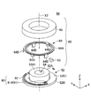
- FIG. 13 is a diagram showing an example of the dimensions of each part of the detector 50 according to the second embodiment.
- FIG. 13 shows an example of the dimensions of each part of the detector 50 when the detector 50 is attached to a bolt shaft having a diameter of 8 mm.
- the lateral width (width in the X-axis direction) of the detector 50 is 30 mm.
- the diameter of the base portion 52A of the strain generating body 52 is 18 mm.
- the vertical width (width in the Z-axis direction) of the detector 50 is 7 mm.
- FIG. 14 is a diagram showing a usage example of the detector 50 according to the second embodiment.
- FIG. 14 shows an example in which the flat plate-shaped member to be fastened 43 is screwed and fixed to the mounting surface 41 by the nut 42B.
- the detector 50 is provided between the nut 42B and the member to be fastened 43.
- a bolt shaft 42A extending upward from the mounting surface 41 penetrates the base portion 52A of the strain-causing body 52 of the member to be fastened 43 and the detection body 50.
- the end portion (end portion on the negative side of the Z axis) of the bolt shaft 42A is fixed to the mounting surface 41.
- the nut 42B is screwed to the bolt shaft 42A from the tip end portion (the end portion on the positive side of the Z axis) of the bolt shaft 42A.
- the nut 42B, together with the bolt shaft 42A constitutes the fastening means 42.
- the strain-causing body 52 of the detection body 50 receives the nut 42B on the upper surface 52A1 of the base portion 52A thereof.
- a fastening axial force in the axial direction (Z-axis direction) of the bolt shaft 42A is applied to the strain generating body 52.
- the diameter of the upper surface 52A1 is larger than the maximum dimension (diagonal length) of the nut.
- the strain-causing body 52 can more reliably receive the fastening axial force applied from the nut 42B by the upper surface 52A1 of the base portion 52A.
- the strain generating body 52 is distorted according to the tightening torque of the nut 42B.
- the strain generated in the strain generating body 52 is detected by each of the strain detecting elements 61A and 61B (see FIGS. 10 to 12) included in the strain detecting module 60 of the detecting body 50.
- the bridge circuit 70 included in the distortion detection module 60 is based on the distortion detected by each of the distortion detection elements 61A and 61B (that is, the change in the resistance value of each of the distortion detection elements 61A and 61B).
- a distortion detection signal corresponding to the tightening torque of the nut 42B is output to the IC 63 included in the distortion detection module 60.
- the IC 63 outputs the distortion detection signal acquired from the bridge circuit 70 to an external device via wireless communication. For example, an external device can determine the tightened state of the nut 42B based on the voltage value indicated by the strain detection signal acquired from the detector 50.
- the distortion detection module 60 may generate electric power by the electromotive coil when the tag reader is held over the strain detection module 60, and wirelessly transmit the distortion detection signal to the tag reader using the electric power. good.
- the distortion detection module 60 can be configured not to include a battery and a memory.
- the present invention is not limited to this, and the distortion detection module 60 may be configured to include at least one of a battery and a memory.
- the detector 50 is the detector 50 that detects the fastening axial force applied in the direction of the central axis X2 by the fastening means 42, and the bolt portion of the fastening means 42 is inserted through the detector 50.
- a strain generating body 52 having a through hole 54 and a strain detecting sensor 61 for detecting the strain of the strain generating body 52 are provided, and the strain generating body 52 has a block-shaped base portion 52A having a through hole 54 and a base portion 52A.
- a thin plate-shaped projecting portion 52B is provided so as to project from the outside in a direction (horizontal direction) intersecting the central axis X2 direction, and the strain detection sensor 61 is provided on the projecting portion 52B.
- the detector 50 according to the second embodiment can install the strain detection sensor 61 on the thin plate-shaped protrusion 52B where the strain-causing body 52 is likely to be distorted, so that even a slight looseness of the fastening member can be detected. can. Therefore, according to the detector 50 according to the second embodiment, it is possible to improve the distortion detection accuracy of the strain detector 52 by the strain detection sensor 61 installed on the protrusion 52B of the strain generator 52.
- the protruding portion 52B is provided at the end portion on the bottom surface side of the base portion 52A, and has a brim shape in a direction (horizontal direction) orthogonal to the central axis X2 direction from the outer circumference of the end portion. Is formed in.
- the detector 50 can be directly affected by the bottom surface side where the distortion of the base portion 52A is large.
- the protruding portion 52B is formed in a brim shape so as to surround the outer periphery of the base portion 52A, the distortion of the base portion 52A can be received by the entire protruding portion 52B.
- the detector 50 according to the second embodiment can reliably transmit the strain of the base 52A of the strain generating body 52 to the protruding portion 52B, and the strain detection sensor installed in the protruding portion 52B of the strain generating body 52.
- the accuracy of detecting the distortion of the strain generating body 52 by 61 can be further improved.
- the bottom surface of the protrusion 52B has grooves 56A and 56B recessed on the upper surface side of the protrusion 52B, and the strain detection sensor 61 has the upper surface 52B1 of the protrusion 52B. And is arranged at a position facing the grooves 56A and 56B.
- the detector 50 according to the second embodiment arranges the strain detection sensor 61 at a position on the protrusion 52B where distortion is more likely to occur, so that the strain of the strain generating body 52 can be detected more reliably. can. Therefore, according to the detector 50 according to the second embodiment, the distortion detection accuracy of the strain detector 52 installed on the strain detector 52 can be further improved.
- the strain detection sensor 61 is the first strain detection element 61A and the first strain detection element 61A and the first strain detection sensor 61 arranged at positions facing each other with the central axis X2 of the through hole 54 in the protruding portion 52B. It has 2 strain detection elements 61B.
- the detector 50 according to the second embodiment can detect the strain at two positions in the horizontal direction on the protruding portion 52B of the strain generating body 52, so that the strain of the strain generating body 52 can be detected with high accuracy. can. Therefore, according to the detector 50 according to the second embodiment, the distortion detection accuracy of the strain detector 52 installed on the strain detector 52 can be further improved.
- the strain generating body 52 has a flat receiving portion for receiving the fastening member of the fastening means 42 around the upper surface 52A1 and the through hole 54.
- the detector 50 according to the second embodiment can more reliably receive the fastening axial force applied from the fastening member by the receiving portion. That is, the fastened state of the fastening member can be more reliably converted into the strain of the strain generating body 52. Therefore, according to the detector 50 according to the second embodiment, the distortion detection accuracy of the strain detector 12 installed in the strain detector 52 can be further improved.
- the detector 50 according to the second embodiment further includes an IC 63 and a communication antenna 64.
- the detector 50 according to the second embodiment can output high-precision detection data representing the strain of the strain-causing body 52 detected by the strain detection sensor 61 to the outside by wireless communication. Therefore, according to the detector 50 according to the second embodiment, it is possible to improve the external detection accuracy of the strain of the strain detector 52 by the strain detection sensor 61 installed in the strain detector 52.
- the IC 63 and the communication antenna 64 are provided on the protrusion 52B.
- the detector 50 according to the second embodiment can arrange the strain detection sensor 61, the IC 63, and the communication antenna 64 in one place on the protrusion 52B. Therefore, according to the detector 50 according to the second embodiment, the detector 50 can be miniaturized.
- the detector 50 according to the second embodiment further includes a sealing resin 65 for sealing the protrusion 52B.
- the detector 50 according to the second embodiment can collectively protect the strain detection sensor 61, the IC 63, and the communication antenna 64 with the sealing resin 65. Therefore, according to the detector 50 according to the second embodiment, it is possible to extend the life of these plurality of constituent members.
- FIG. 15 is a diagram showing a system configuration of the detection system 100 according to the third embodiment. As shown in FIG. 15, the detection system 100 includes a detector 120 and a reading device 140.
- the detector 120 is a device that detects the fastening axial force applied in the axial direction by the fastening means. As shown in FIG. 15, the detector 120 includes a first strain detection sensor 122, a second strain detection sensor 123, and a control circuit 124.
- the first strain detection sensor 122 is installed on the planar side surface of the strain generating body 121, and detects the strain of the strain generating body 121 in the direction of the central axis X3.
- the first strain detection sensor 122 outputs a first detection value representing the axial strain of the detected strain-causing body 121.
- the second strain detection sensor 123 is installed on the planar side surface of the strain generating body 121, and detects the strain in the radial direction (direction orthogonal to the central axis X3 direction) of the strain generating body 121.
- the second strain detection sensor 123 outputs a second detection value representing the radial strain of the detected strain generating body 121.
- the first strain detection sensor 122 and the second strain detection sensor 123 have the same temperature characteristics as each other.
- the control circuit 124 has an antenna 124A.
- the control circuit 124 transmits the difference value between the first detected value detected by the first strain detection sensor 122 and the second detected value detected by the second strain detection sensor 123 via the antenna 124A. , Wirelessly transmit to the reading device 140. Further, the control circuit 124 wirelessly transmits the wireless ID of the detector 120 to the reading device 140 via the antenna 124A.
- the reading device 140 is a device that acquires various information from the detector 120. As shown in FIG. 15, the reading device 140 includes a main body 140A and a cover 140B.
- the cover 140B is a container-shaped member having an open bottom surface, which is arranged so as to cover the upper part of the detector 120 when various information is acquired from the detector 120 (see FIG. 16).
- the cover 140B has an antenna 141A and a radiation thermometer 144.
- the antenna 141A receives various information (difference value between the first detection value and the second detection value and the radio ID) wirelessly transmitted from the detector 120.
- the radiation thermometer 144 measures the temperature of the detector 120 in a non-contact manner. Then, the radiation thermometer 144 outputs a temperature measurement value representing the measured temperature of the detector 120.
- the main body 140A is provided separately from the cover 140B.
- the main body 140A has a communication unit 141 and a control unit 143.
- As the main body for example, a PC (Personal Computer) is used, but the present invention is not limited to this.
- the communication unit 141 is connected to the antenna 141A provided on the cover 140B.
- the communication unit 141 receives various information (difference value between the first detection value and the second detection value and the radio ID) wirelessly transmitted from the detector 120 via the antenna 141A.
- the communication unit 141 transmits a radio wave conforming to the radio ID protocol to the detector 120 via the antenna 141A.
- the control circuit 124 of the detector 120 receives the signal transmitted from the communication unit 141 to generate electric power for driving the sensor and the IC.
- the control circuit 124 of the detector 120 transmits various information (difference value between the first detected value and the second detected value and the radio ID) to the reader 140 by the reflected wave for the radio wave from the reader 140. ..
- the communication unit 141 of the reading device 140 receives various information (difference value between the first detected value and the second detected value and the wireless ID) transmitted from the detector 120 via the antenna 141A. ..
- the 920 MHz band is used as the radio communication frequency between the reader 140 and the detector 120, but other frequency bands may be used.
- the control unit 143 performs various controls on the reading device 140. For example, the control unit 143 acquires various information (difference value between the first detected value and the second detected value, wireless ID, temperature measured value), corrects the temperature of the data acquired from the detector 120, and detects the detector. Looseness determination of the fastening member based on the data acquired from 120, notification of the looseness determination result to the operator, recording of the looseness determination result, transmission / reception of various information to an external device (for example, a server, etc.), and the like are performed.
- various information difference value between the first detected value and the second detected value, wireless ID, temperature measured value
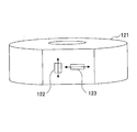
- FIG. 16 is a perspective view showing the appearance of the upper surface side of the detector 120 according to the third embodiment.
- the detector 120 shown in FIG. 16 is a device having a strain-causing body 121 having a substantially cylindrical shape.
- the detector 120 is installed between the fastening member (bolt or nut) and the fastening member when the fastening member is screwed and fixed to a predetermined mounting surface (for example, a wall surface). It is possible to detect the fastening axial force applied in the axial direction of the central shaft X3 by fastening the fastening member.
- the detector 120 includes a strain generator 121, a first strain detection sensor 122, a second strain detection sensor 123, a control circuit 124, and a case 126.
- the strain generating body 121 is a block-shaped member having a substantially cylindrical shape.
- the strain-causing body 121 is formed by preferably using a metal material such as stainless steel.
- a through hole 121A is formed so as to penetrate the strain-causing body 121 in the vertical direction (Z-axis direction) along the central axis X3.
- the through hole 121A is a portion through which the bolt portion of the fastening means is inserted.
- the upper surface 121B of the strain generating body 121 is flat.
- the upper surface 121B of the strain generating body 121 functions as a flat receiving portion for receiving the fastening member (bolt or nut).
- four planar flat portions 121C are formed on the outer peripheral surface of the strain generating body 121 at 90 ° intervals.
- the pair of flat surface portions 121C are parallel to each other with the through hole 121A interposed therebetween, and are both parallel to the YZ plane.
- the other pair of flat surface portions 121C are parallel to each other with the through hole 121A interposed therebetween, and are both parallel to the XZ plane.
- the four flat surface portions 121C are formed, for example, by cutting out a part of the outer peripheral surface of the strain-causing body 121 before processing having a cylindrical shape in parallel with the XZ or YZ plane.
- the first strain detection sensor 122 is provided on the flat surface portion 121C of one of the four flat surface portions 121C of the strain generating body 121.
- the first strain detection sensor 122 detects the strain of the strain generating body 121 in the central axis X3 direction as the first detected value, and outputs the first detected value to the control circuit 124.
- the first strain detection sensor 122 is arranged with respect to the flat surface portion 121C so that the strain detection element is subjected to positive distortion (distortion in the compression direction).
- the second strain detection sensor 123 is provided on the other flat surface portion 121C of the four flat surface portions 121C of the strain generating body 121.
- the second strain detection sensor 123 detects the strain in the radial direction of the strain generating body 121 as the second detection value, and outputs the second detection value to the control circuit 124.
- the second strain detection sensor 123 is arranged so that a negative strain (distortion in the tensile direction) is generated in the strain detection element with respect to the flat surface portion 121C.
- the second strain detection sensor 123 may be a non-flexible sensor with a fixed resistance. Further, in the example shown in FIG.
- four flat surface portions 121C are formed on the outer peripheral surface of the strain generating body 121, but the present invention is not limited to this.
- one flat surface portion 121C is formed on the outer peripheral surface of the strain generating body 121, and two strain detection sensors 122 and 123 are arranged on the one flat surface portion 121C. You may do so.
- the control circuit 124 is provided outside the outer peripheral surface of the strain generating body 121 and in the first cavity portion 126B of the case 126.
- the control circuit 124 includes an antenna 124A (see FIG. 15), an IC 124B, and the like.
- the control circuit 124 sets a difference value between the first detected value output from the first strain detection sensor 122 and the second detected value output from the second strain detection sensor 123 via the antenna 124A. Wireless transmission to the reading device 140. Further, the control circuit 124 wirelessly transmits the radio ID of the detector 120 stored in the memory included in the control circuit 124 to the reading device 140 via the antenna 124A.
- the first detected value includes an error component due to temperature in the first strain detection sensor 122
- the second detected value includes an error component due to temperature in the second strain detection sensor 123. Since the first strain detection sensor 122 and the second strain detection sensor 123 have the same temperature characteristics, the error component of the first detection value and the error component of the second detection value are the same as each other.
- the control circuit 124 wirelessly transmits the difference value between the first detected value and the second detected value to the reading device 140, and wirelessly transmits the detected value from which the error components of both signals are removed to the reading device 140. Can be sent.
- the present invention is not limited to this, and the control circuit 124 may wirelessly transmit the first detected value and the second detected value to the reading device 140. In this case, the control unit 143 of the reading device 140 may calculate the difference value between the first detected value and the second detected value.
- the case 126 is an annular member that is expanded outward in the radial direction from the outer peripheral surface of the strain generating body 121 and surrounds the outer peripheral surface of the strain generating body 121. Note that FIG. 16 shows a state in which the lid portion of the case 126 is removed.
- the case 126 has an inner cylinder portion 126A that penetrates the case 126 in the vertical direction.
- the case 126 is integrated with the strain generating body 121 by fitting the strain generating body 121 into the inner cylinder portion 126A.
- the case 126 is formed, for example, by injection molding a resin material.
- the case 126 has a first cavity 126B and a second cavity 126C.
- a control circuit 124 is arranged in the first cavity portion 126B.
- control circuits can be additionally arranged in the second cavity portion 126C.
- the detector 120 wirelessly transmits both the difference value and the wireless ID by the control circuit 124.
- the detector 120 may be configured to wirelessly transmit either the difference value or the wireless ID by another control circuit arranged in the second cavity portion 126C.
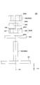
- FIG. 17 is a diagram showing a configuration of a cover 140B included in the reading device 140 according to the third embodiment.
- the cover 140B is arranged so as to cover the upper side and the side surface of the detector body 120 when acquiring various information from the detector body 120 (that is, when inspecting the fastening state of the fastening member). It is a container-shaped member with an open bottom.
- An antenna 141A and a radiation thermometer 144 are provided on the ceiling surface 140Bb of the cover 140B.
- the antenna 141A is provided at a position facing the control circuit 124 of the detector 120, and various information wirelessly transmitted from the control circuit 124 (difference value between the first detection value and the second detection value and the radio ID).
- the radiation thermometer 144 is provided at a position facing the upper surface of the detection body 120, and measures the temperature of the detection body 120 by irradiating the upper surface of the detection body 120 with infrared rays or visible light. Then, the radiation thermometer 144 outputs a temperature measurement value representing the measured temperature to the main body 140A.
- the reading device 140 according to the third embodiment is located closer to the sensors 122 and 123 as compared with the case where the temperature of the bolt is measured by directly measuring the temperature of the detector 120 with the radiation thermometer 144. The temperature can be measured. Further, the reading device 140 according to the third embodiment controls the antenna 141A as compared with the case where the temperature of the bolt is measured by directly measuring the temperature of the detector 120 with the radiation thermometer 144. Since it can be brought closer to 124, the communication accuracy between the antenna 141A and the control circuit 124 can be further improved. However, the present invention is not limited to this, and the temperature of the bolt may be measured by the radiation thermometer 144.
- the cover 140B is formed by using a metal material (for example, aluminum, iron, etc.) that does not easily transmit radio waves so that the radio waves do not leak to the outside. Further, the cover 140B has a sheet-shaped radio wave absorber 145 attached to the entire surface of the ceiling surface 140Bb and the inner wall surface 140Bc exposed to the internal space 140Ba so that the radio waves do not leak to the outside. As the radio wave absorber 145, a conductive radio wave absorbing material, a dielectric radio wave absorbing material, a magnetic radio wave absorbing material, or the like is used. In this way, the cover 140B is configured so that radio waves do not leak to the outside, so that even when a plurality of detectors 120 are installed close to each other, they are transmitted from the other detectors 120. It is possible to prevent false detection of radio waves.
- a metal material for example, aluminum, iron, etc.
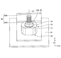
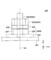
- FIG. 18 is a diagram showing a configuration of a control circuit 124 included in the detector 120 according to the third embodiment.
- a first strain detection sensor 122 and a second strain detection sensor 123 are provided on the outer peripheral surface of the strain generating body 121.
- the strain generating body 121 having a washer shape contracts in the central axis X3 direction and expands in the radial direction by being fastened by a fastening member (bolt or nut).
- the ratio of contraction to expansion in the strain-causing body 121 is determined by the Poisson's ratio of the material used for the strain-causing body 121 and the shape of the strain-causing body 121.
- the first strain detection sensor 122 detects the strain of the strain generating body 121 in the central axis X3 direction by contracting together with the strain generating body 121 to lower the resistance value. Further, at this time, the second strain detection sensor 123 expands together with the strain generating body 121 to increase the resistance value, so that the strain detecting sensor 123 is in the radial direction of the strain generating body 121 (the direction orthogonal to the central axis X3 direction). Detect distortion.
- the second strain detection sensor 123 may be a non-flexible sensor with a fixed resistance.
- first strain detection sensor 122 and the second strain detection sensor 123 have the same temperature characteristics. Therefore, the first detected value output from the first strain detection sensor 122 and the second detected value output from the second strain detection sensor 123 have an error component due to the influence of the same temperature. include.
- the control circuit 124 has a first detection circuit 1801 that outputs a first detection value by driving the first distortion detection sensor 122, and a second distortion detection sensor 123. It has a second detection circuit 1802 and a differential circuit 1803 that output a second detection value by driving the differential circuit 1803, and is output from the first detection circuit 1801 by the differential circuit 1803. It is possible to output the difference value between the detection value of 1 and the second detection value output from the second detection circuit 1802.
- control circuit 124 has an ID generation circuit 1804, and the ID generation circuit 1804 outputs the radio ID of the detector 120 stored in the control circuit 124. Can be done.
- control circuit 124 includes a rectifier circuit 1805, a transmission circuit 1806, and an antenna 124A, and the difference value between the first detection value and the second detection value and the detector via the antenna 124A.
- the wireless ID of 120 can be wirelessly transmitted to the reading device 140.
- the control circuit 124 removes common components (error due to the influence of temperature, noise, etc.) of the two sensors 122 and 123, and changes the distortion component and the distortion in the direction of the central axis X3 of the strain generating body 121.
- the detected value which is the sum of the change components of the radial strain of the body 121, can be wirelessly transmitted to the reading device 140.
- control circuit 124 an IC having an interface for a sensor is used as the control circuit 124.
- the control circuit 124 can not only transmit the radio ID but also transmit the difference value between the first detected value and the second detected value.
- control circuit 124 can generate electric power by receiving the radio wave transmitted from the reading device 140, and the sensors 122 and 123 and the control circuit 124 can be driven by the electric power. That is, the control circuit 124 can operate even if the battery is not mounted, and maintenance related to the battery such as battery replacement and charging is not required.
- FIG. 19 is a flowchart showing a work procedure of the detector 120 according to the third embodiment.
- the correction data (inclination of the sensor output with respect to the applied load, the sensor output with respect to the temperature environment) is measured. Then, these measured values are associated with the radio ID of the detector 120 (step S1901).
- correction data and a correction table are created from the measured values (temperature, strain sensor value), the radio ID of the detector 120, and the data at the time of the process in which the detector 120 was created, and stored in the reading device 140. (Step S1902).
- the reading device 140 is brought close to the detector 120, and data measurement (temperature, strain sensor value) and ID identification immediately after the work are performed.
- data measurement temperature, strain sensor value
- ID identification ID identification immediately after the work are performed.
- the initial looseness determination is performed (step S1903).
- the reading device 140 is brought close to the detector 120 to read the temperature, the sensor value, and the wireless ID (step S1904).
- step S1905 the measured values (temperature, strain sensor value), wireless ID, correction data, and correction table are compared with the bolt loosening threshold value (step S1905). Then, it is determined whether or not the determination result is "OK" (step S1906).
- step S1906 If it is determined in step S1906 that the determination result is not "OK" (step S1906: No), corrective action such as retightening is carried out (step S1907). Then, the work is returned to step S1904.
- step S1906 If it is determined in step S1906 that the determination result is "OK" (step S1906: Yes), the measurement result is saved (step S1908). Then, the series of operations shown in FIG. 19 is completed.
- the resistance change type strain sensor examples include a metal thin film method (CuNi, NiCr, etc.), a piezo method in which silicon is doped with impurities, and the like. In each case, strain detection is performed by changing the resistance value of the strain detecting element due to a minute change (strain) in the length of the strain detecting element.
- the resistance value change ⁇ R of the resistance change type strain sensor is affected by temperature, and is generally given by the following mathematical formula (1).
- ⁇ R resistance value change due to strain + resistance value change of gauge material due to temperature + resistance value change of gauge rate due to temperature ... (1)
- the change in the resistance value of the gauge material due to temperature and the change in the resistance value of the gauge ratio due to temperature are non-linear characteristics with respect to temperature, and when the temperature difference is large, the resistance change due to the original strain. May have a significant effect on the value. Therefore, in order to measure the strain accurately, it is necessary to correct the temperature.
- the gauge ratio K is "2.1”
- the coefficient of resistance change coefficient TCR of the gauge material with temperature is "14 ppm / ° C”
- the temperature of the gauge ratio is "-300 ppm / ° C.”
- ⁇ R Amount of change in resistance value of strain sensor
- R Resistance value of strain sensor
- ⁇ Strain TCR: Coefficient of resistance change of gauge material due to temperature
- ⁇ t Temperature change (° C.)
- K Gauge rate of strain sensor
- TCGF Temperature coefficient of gauge rate of strain sensor
- the detection system 100 can detect the strain of the strain generating body 121 with high accuracy by performing temperature correction on the first detected value and the second detected value. Specifically, the detection system 100 outputs a difference value between the first detection value and the second detection value from the detector 120 to obtain a common component of the first detection value and the second detection value. By removing it, temperature correction is performed for the first detected value and the second detected value. Further, in the detection system 100, the control unit 143 of the reading device 140 sets the first detection value based on the temperature of the detector 120 measured by the radiation thermometer 144 and the correction data created in advance. By correcting the difference value (or the first detected value and the second detected value) from the second detected value, the temperature of the first detected value and the second detected value is corrected.
- FIG. 20 is a graph showing an example of correction data for offset correction and inclination correction of the sensor value used by the reading device 140 according to the third embodiment.
- FIG. 21 is a graph showing an example of correction data for temperature correction of the sensor value used by the reading device 140 according to the third embodiment.
- the control unit 143 of the reading device 140 according to the third embodiment can perform offset correction and tilt correction of the sensor value by using the correction data shown in FIG. Further, the control unit 143 of the reading device 140 according to the third embodiment can correct the temperature of the sensor value by using the correction data shown in FIG.
- the load applied to the sensor is changed from the state where the load is not applied to the sensor under a constant temperature, and the sensor value (measured value) of each of the plurality of loads is obtained.
- the sensor value measured value
- it is created as a correction value (approximate formula or correction table) for performing offset correction and tilt correction of the sensor value.
- the temperature of the sensor atmosphere is changed under the condition that a constant load is applied to the sensor, and the sensor values (measured values) of the plurality of atmosphere temperatures are obtained. Is created as a correction value (approximate formula or correction table) for performing temperature correction of the sensor value.
- FIG. 22 is a diagram showing an example of input / output characteristics of the detector 120 according to the third embodiment.
- the input load F, the strain ⁇ , the resistance value R of the strain sensor, and the gauge factor K of the strain sensor are shown.
- FIG. 23 is a graph showing changes in resistance values with respect to distortion of sensors 122 and 123 included in the detector 120 according to the third embodiment. As shown in FIG. 23, the resistance values of the sensors 122 and 123 linearly decrease as the amount of strain increases. However, FIG. 23 shows the resistance value when the sensors 122 and 123 are distorted in the contraction direction. When distortion occurs in the direction in which the sensors 122 and 123 extend, the resistance values of the sensors 122 and 123 linearly increase as the amount of distortion increases, contrary to the graph shown in FIG. 23.
- FIG. 24 is a diagram showing a first modification of the installation positions of the sensors 122 and 123 in the strain generating body 121 according to the third embodiment.
- FIG. 25 is a diagram showing a second modification of the installation positions of the sensors 122 and 123 in the strain generating body 121 according to the third embodiment.
- the sensors 122 and 123 are provided side by side in the vertical direction (central axis X3 direction) on the same flat surface portion 121C of the strain generating body 121.
- the sensors 122 and 123 are provided side by side in the left-right direction (direction orthogonal to the central axis X3 direction) on the same flat surface portion 121C of the strain generating body 121.
- FIG. 26 is a diagram showing the evaluation results of the detector 120 according to the third embodiment.
- the configuration A detects a case where the sensors 122 and 123 are provided side by side in the vertical direction (central axis X3 direction) on the same flat surface portion 121C of the strain generating body 121 as shown in FIG. 24.
- the evaluation result of the body 120 is shown.
- the sensors 122 and 123 are provided side by side in the left-right direction (direction orthogonal to the central axis X3 direction) on the same flat surface portion 121C of the strain generating body 121.
- the evaluation result of the detector 120 in the case of being present is shown.
- configuration C shows the evaluation result of the detector 120 when the sensors 122 and 123 are separately provided on each of the two plane portions 121C of the strain generating body 121, as shown in FIG. show.
- the sensors 122 and 123 can be installed at the same height position on the side surface of the strain generating body 121, so that the strain generating body 121 can be installed. It is possible to realize thinning.
- the sensors 122 and 123 can be installed close to each other on the same flat surface portion 121C of the strain generating body 121, so that the sensors 122 and 123 can be installed close to each other.
- the temperature difference between them can be suppressed, and the temperature correction between the two can be performed with high accuracy.
- the sensors 122 and 123 can be installed close to each other on the same flat surface portion 121C of the strain generating body 121, so that the sensors 122 and 123 are combined with the sensors 122 and 123.
- the connection distance with the control circuit 124 can be shortened.
- one sensor can be installed for each of the two flat surface portions 121C of the strain generating body 121, so that a large sensor is installed. It is possible to suppress the adhesion failure of the sensor.
- the detector 120 is the detector 120 that detects the fastening axial force applied in the axial direction by the fastening means 150, and the bolt portion 151A of the fastening means 150 is inserted through the detector 120.
- a strain generating body 121 having a through hole 121A, a first strain detecting sensor 122 installed on a flat surface portion 121C which is a planar side surface of the strain generating body 121, and detecting the strain of the strain generating body 121, and a strain generating body. It is installed on the flat surface portion 121C which is a flat side surface of the 121, and includes a second strain detection sensor 123 for detecting the distortion of the strain generating body 121.
- the detector 120 according to the third embodiment uses the first detection value by the first strain detection sensor 122 and the second detection value by the second strain detection sensor 123, and uses the first detection value. It is possible to remove common components (error due to the influence of temperature, noise, etc.) included in the detected value and the second detected value. Therefore, according to the detector 120 according to the third embodiment, it is possible to improve the accuracy of detecting the strain of the strain generator 121 by the strain gauge installed in the strain generator 121.
- the first strain detection sensor 122 and the second strain detection sensor 123 have the same temperature characteristics as each other.
- the common components (error due to the influence of temperature, noise, etc.) included in the first detected value and the second detected value are substantially the same as each other.
- the components can be removed with higher accuracy.
- the first strain detection sensor 122 detects the distortion in the axial direction of the strain generator 121
- the second strain detection sensor 123 detects the axial strain of the strain generator 121. Detects distortion in the direction orthogonal to the direction.
- the detector 120 obtains the difference value between the first detected value and the second detected value, so that the common component included in the first detected value and the second detected value is included in the first detected value and the second detected value. It is possible to obtain the amount of strain of the strain generating body 121 after the removal of the strained body 121 as a strain detection value representing with high accuracy.
- the detector 120 according to the third embodiment further includes a control circuit 124 that wirelessly transmits the difference value between the first detected value and the second detected value to the reading device 140.
- the detector 120 is a strain that accurately represents the strain amount of the strain generator 121 after the common components included in the first detection value and the second detection value are removed.
- the detected value can be wirelessly transmitted to the reading device 140.
- control circuit 124 further wirelessly transmits the wireless ID of the detector 120 to the reader 140.
- the detector 120 according to the third embodiment can easily associate the strain detection value acquired from the detector 120 with the identification information of the detector 120 in the reading device 140.
- the detection system 100 includes a detector 120 and a reading device 140.
- the reading device 140 can acquire a distortion detection value that accurately represents the amount of distortion of the strain generating body 121 from the detecting body 120. Therefore, according to the detection system 100 according to the third embodiment, the reading device 140 can grasp the fastening state by the fastening means 150 with higher accuracy.
- the reading device 140 has a cover 140B arranged so as to cover the detecting body 120 when reading data from the detecting body 120.
- the detection system 100 according to the third embodiment can prevent erroneous detection of the data wirelessly transmitted from the other detector 120 when reading the data wirelessly transmitted from the detector 120.
- the shape of the cover 140B can be made to match the shape of the detection body 120, whereby the position of the cover 140B with respect to the detection body 120 can be easily performed. It will be possible.
- the reading device 140 receives the difference value and the radio ID at a position facing the control circuit 124 in the cover 140B arranged so as to cover the detection body 120. Has.
- the detection system 100 can improve the communication accuracy between the control circuit 124 and the antenna 141A.
- the reading device 140 measures the temperature of the detection body 120 at a position facing the detection body 120 on the cover 140B arranged so as to cover the detection body 120. It has a total of 144.
- the detection system 100 can measure the temperature closer to the sensor temperatures 122 and 123.
- the reading device 140 includes a control unit 143 that corrects a difference value based on the temperature of the detector 120 measured by the radiation thermometer 144.
- the detection system 100 can calculate a strain detection value that accurately represents the strain amount of the strain generating body 121.
- the detection system 100 has a failure determination function of the sensors 122 and 123.
- the ratio of the contraction strain in the central axis X3 direction of the strain-causing body 121 to the extension strain in the radial direction of the strain-causing body 121 is the origin. It is determined by the Poisson's ratio of the material used for the strain 121 (for example, about 0.3 for stainless steel). This Poisson's ratio is constant unless a large deformation such as plastic deformation occurs in the strain generating body 121.
- the ratio of the first detection value output from the first strain detection sensor 122 to the second detection value output from the second strain detection sensor 123 is determined by the failure determination function. If the ratio deviates significantly from the predetermined ratio (ie, Poisson's ratio) (for example, the normal value is 0.3, but is outside the range of 0.2 to 0.4), "1st It can be determined that at least one of the strain detection sensor 122 and the second strain detection sensor 123 is out of order (for example, deformation, disconnection, peeling of adhesive, etc.).
- the failure determination function may be provided in the control circuit 124 of the detector 120, or may be provided in the control unit of the reading device 140.
- a nut is used as a fastening member, but the present invention is not limited to this, and a bolt may be used as a fastening member.
- the flat surface portion 16A is provided with four strain detecting elements 21A to 21D, but the present invention is not limited to this, and for example, the flat surface portion 16A is provided with three or less or five or more strains.
- a detection element may be provided.
- the strain detecting elements 21A and 21B may be provided on the flat surface portion 16A, and the strain detecting elements 21C and 21D may not be provided.
- the strain detecting elements 21C and 21D may be provided on the flat surface portion 16A so that the strain detecting elements 21A and 21B are not provided.
- a distortion element may be provided on both the flat surface portions 16A and 16B.
- the configuration is preferably provided with a pair of flat surfaces 16A and 16B, but the present invention is not limited to this, and for example, a configuration in which a flat surface portion on only one side on which a distortion element is provided is provided is also possible. good.
- the flat surface portion 16A is formed at a position closer to the central axis X1 than the flat surface portion 16B, but the present invention is not limited to this, and for example, the flat surface portion 16A and the flat surface portion 16B are equidistant from the central axis X1. It may be configured to be arranged.
- strain detection elements 61A and 61B are provided on the upper surface 52B1 of the protrusion 52B, but the present invention is not limited to this, and for example, three or more strain detection elements are provided on the upper surface 52B1. You may.
- the strain-causing body 12 has a substantially cylindrical shape, but the present invention is not limited to this.
- the strain-causing body 12 may have a prismatic shape or the like having a flat surface portion on the side surface.
- the base portion 52A of the strain generating body 52 has a substantially cylindrical shape, but the present invention is not limited to this.
- the base portion 52A may have a prismatic shape or the like in which a protruding portion is provided on the outside.
- the protruding portion 52B is preferably formed in a horizontal flange shape from the outer periphery of the end portion on the bottom surface side of the base portion 52A, but the present invention is not limited to this.
- the 52B may be provided so as to project horizontally from the outside (outer peripheral surface) of the base portion 52A.
- thermometer 144 As a method of temperature compensation of the sensor detection value, a method of outputting the difference value between the first detection value and the second detection value to the reading device 140 and a method of emitting radiation in the reading device 140.
- Two methods of temperature correction based on the measured value of the thermometer 144 have been described, but by using these techniques, the temperature of the sensor detection value is compensated as in the following modifications 1 to 3. May be good.
- the detector 120 outputs the difference value between the first detected value and the second detected value to the reading device 140, and the reading device 140 emits the difference value between the first detected value and the second detected value.
- the temperature may be corrected based on the measured value of the thermometer 144 (that is, the temperature of the detector 120).
- both the first detected value and the second detected value are output from the detector 120 to the reading device 140, and both the first detected value and the second detected value are radiated by the reading device 140.
- the temperature may be corrected based on the measured value of the thermometer 144.
- the detector 120 is provided with any one of the first strain detection sensor 122 and the second strain detection sensor 123, and the detection value of the one sensor is output to the reading device 140 to be output to the reading device.
- the detected value of the one sensor may be temperature-corrected based on the measured value of the radiation thermometer 144.
- FIG. 27 is an exploded view of the fastening structure 200 according to the fourth embodiment.
- FIG. 28 is a diagram showing a fastening state of the fastening structure 200 according to the fourth embodiment.
- the fastening member 203 is screwed to the mounting surface 201 by using the fastening means 200A including the nut 206 and the bolt shaft 202. It is fixed and fixed.
- the fastening structure 200 has a mounting surface 201, a bolt shaft 202, a fastened member 203, a strain generating body 205, and a washer 204 in this order from the mounting surface 201 side (Z-axis negative side). And a nut 206.
- the mounting surface 201 is a flat surface on which the member to be fastened 203 is mounted.
- the member to be fastened 203 is a metal and flat plate-shaped member that is attached to the attachment surface 201.
- the fastened member 203 is formed with a through hole 203A that penetrates the fastened member 203 in the vertical direction.
- a bolt shaft 202 can be inserted into the through hole 203A.
- the bolt shaft 202 is a metal and rod-shaped member that stands perpendicular to the mounting surface 201 and extends along the central shaft X4.
- a screw thread (not shown) into which the nut 206 can be screwed is formed on the outer peripheral surface of the bolt shaft 202.
- the lower end of the bolt shaft 202 is fixed to the member to be fastened 203.
- the bolt shaft 202 may penetrate the mounting surface 201.
- the strain generating body 205 is a block-shaped member having a substantially thin cylindrical shape.
- the strain-causing body 205 is formed by preferably using a metal material such as stainless steel.
- As the strain-causing body 205 the strain-causing body 12 described in the first embodiment, the same strain-generating body 52 as described in the second embodiment, or a modified version thereof can be used.
- a through hole 205A that penetrates the strain-causing body 205 in the vertical direction is formed.
- a bolt shaft 202 can be inserted into the through hole 205A.
- the strain-causing body 205 constitutes the detector body 200B together with the strain detection module 207 integrated with the strain-causing body 205.
- the strain detection module 207 the strain detection module 20 described in the first embodiment, the same strain detection module 60 as described in the second embodiment, or a modified version thereof can be used. ..
- the upper surface of the strain generating body 205 is a surface that comes into contact with the lower surface of the washer 204, and the lubricant 208 (grease, oil, etc.) is applied to the upper surface of the strain generating body 205.
- the washer 204 is a metal and disk-shaped member.
- the washer 204 is provided between the strain generating body 205 and the nut 206.
- a through hole 204A that penetrates the washer 204 in the vertical direction is formed.
- a bolt shaft 202 can be inserted into the through hole 204A.
- the diameter of the washer 204 is preferably larger than either the diameter of the nut 206 or the diameter of the strain generating body 205.
- the nut 206 is a metal member that can be screwed onto the bolt shaft 202.
- the outer peripheral surface of the nut 206 is formed in a hexagonal shape.
- a screw hole 206A that penetrates the nut 206 in the vertical direction is formed.
- a screw thread (not shown) that can be screwed into the bolt shaft 202 is formed on the inner peripheral surface of the screw hole 206A.
- the fastening structure 200 configured in this way has the fastened member 203, the strain generating body 205, and the washer 204 between the mounting surface 201 and the nut 206 in this order from the mounting surface 201 side.
- the mounting surface 201 is formed by screwing the nut 206 to the bolt shaft 202 in a state where the bolt shaft 202 is inserted into each of the member to be fastened 203, the strain generating body 205, and the washer 204.
- the member to be fastened 203, the strain-causing body 205, and the washer 204 are fixed.
- the strain-causing body 205 is distorted according to the tightening torque of the nut 206 by applying the fastening axial force in the axial direction (Z-axis direction) of the bolt shaft 202.
- the strain generated in the strain-causing body 205 is detected by the strain detection module 207.
- the distortion detection module 207 outputs a distortion detection signal representing a voltage value corresponding to the detected distortion to an external device via wireless communication. For example, an external device can determine the tightened state of the nut 206 based on the voltage value indicated by the strain detection signal acquired from the strain detection module 207.
- the fastening structure 200 according to the fourth embodiment is provided with the washer 204 between the strain generating body 205 and the nut 206, so that the strain generating body 205 is compared with a configuration in which the washer 204 is not provided.
- the strain generated in the nut 206 can be more accurately reflected in the tightening torque of the nut 206.
- the fastening structure 200 according to the fourth embodiment can determine the tightening torque of the nut 206 with higher accuracy based on the strain detection signal.
- Bolt shaft 202 size M24 Material of bolt shaft 202: SUS304 Material of nut 206: SUS304 Material of washer 204: SUS304 Washer 204 thickness: 4 mm Tightening torque of nut 206: 400 Nm (1st time), 200 Nm (2nd time)
- FIG. 29 and 30 are graphs showing the measurement results of the strain amount of the strain-causing body 205 in the fastening structure 200 (when the washer 204 is not provided) according to the fourth embodiment.
- FIG. 29 shows the result of the first measurement.
- FIG. 30 shows the result of the second measurement.
- the amount of strain of the strain generating body 205 when the nut 206 is tightened is relatively small.
- the lower surface of the nut 206 directly abuts on the upper surface of the strain generating body 205, so that galling occurs between the lower surface of the nut 206 and the upper surface of the strain generating body 205. This is because the fastening axial force applied to the strain generating body 205 is reduced.
- FIG. 31 and 32 are graphs showing the measurement results of the strain amount of the strain-causing body 205 in the fastening structure 200 (when the washer 204 is provided) according to the fourth embodiment.
- FIG. 31 shows the result of the first measurement.
- FIG. 32 shows the result of the second measurement.
- the washer 204 when the washer 204 is provided in the fastening structure 200, the amount of strain of the strain generating body 205 when the nut 206 is tightened is relatively large.
- the washer 204 is interposed between the lower surface of the nut 206 and the upper surface of the strain generating body 205, so that the lower surface of the nut 206 and the upper surface of the strain generating body 205 are separated from each other. This is because galling is less likely to occur, and the fastening axial force applied to the strain generating body 205 is less likely to decrease.
- the fastening structure 200 Since the fastening structure 200 according to the fourth embodiment has the following configuration, galling between the lower surface of the nut 206 and the upper surface of the strain generating body 205 is less likely to occur.
- the hardness of the washer 204 is equal to or higher than the hardness of the nut 206.
- the upper and lower surfaces of the washer 204 are smooth.
- the fastening structure 200 according to the fourth embodiment may have the following configuration, and in this case as well, galling between the lower surface of the nut 206 and the upper surface of the strain generating body 205 is less likely to occur. It becomes.
- the fastening structure 200 according to the fourth embodiment may have a configuration in which the head of the bolt is tightened instead of the configuration in which the nut 206 is tightened. In this case, between the head of the bolt and the strain generating body 205.
- the washer 204 may be provided.
Landscapes
- Physics & Mathematics (AREA)
- General Physics & Mathematics (AREA)
- Force Measurement Appropriate To Specific Purposes (AREA)
- Measurement Of Length, Angles, Or The Like Using Electric Or Magnetic Means (AREA)
Priority Applications (4)
| Application Number | Priority Date | Filing Date | Title |
|---|---|---|---|
| DE112021001705.5T DE112021001705T5 (de) | 2020-03-19 | 2021-03-17 | Detektor und detektionssystem |
| JP2022508420A JP7352724B2 (ja) | 2020-03-19 | 2021-03-17 | 検出体 |
| CN202180018375.9A CN115244373B (zh) | 2020-03-19 | 2021-03-17 | 检测体以及检测系统 |
| US17/895,675 US12467809B2 (en) | 2020-03-19 | 2022-08-25 | Detector and detecting system |
Applications Claiming Priority (4)
| Application Number | Priority Date | Filing Date | Title |
|---|---|---|---|
| JP2020049851 | 2020-03-19 | ||
| JP2020-049851 | 2020-03-19 | ||
| JP2020058466 | 2020-03-27 | ||
| JP2020-058466 | 2020-03-27 |
Related Child Applications (1)
| Application Number | Title | Priority Date | Filing Date |
|---|---|---|---|
| US17/895,675 Continuation US12467809B2 (en) | 2020-03-19 | 2022-08-25 | Detector and detecting system |
Publications (1)
| Publication Number | Publication Date |
|---|---|
| WO2021187542A1 true WO2021187542A1 (ja) | 2021-09-23 |
Family
ID=77768425
Family Applications (1)
| Application Number | Title | Priority Date | Filing Date |
|---|---|---|---|
| PCT/JP2021/010929 Ceased WO2021187542A1 (ja) | 2020-03-19 | 2021-03-17 | 検出体および検出システム |
Country Status (5)
| Country | Link |
|---|---|
| US (1) | US12467809B2 (https=) |
| JP (1) | JP7352724B2 (https=) |
| CN (1) | CN115244373B (https=) |
| DE (1) | DE112021001705T5 (https=) |
| WO (1) | WO2021187542A1 (https=) |
Cited By (2)
| Publication number | Priority date | Publication date | Assignee | Title |
|---|---|---|---|---|
| GB2601330B (en) * | 2020-11-26 | 2023-05-03 | Tenscon Ltd | A load-indicating device |
| JP2024111783A (ja) * | 2023-02-06 | 2024-08-19 | 広州市市政工程試験検測有限公司 | 超薄型力覚センサ、モニタリングシステム、モニタリング方法及び適用 |
Families Citing this family (3)
| Publication number | Priority date | Publication date | Assignee | Title |
|---|---|---|---|---|
| WO2021142569A1 (zh) * | 2020-01-13 | 2021-07-22 | 舍弗勒技术股份两合公司 | 传感装置和轴承组件 |
| EP4174465A1 (en) * | 2021-10-27 | 2023-05-03 | Canon Kabushiki Kaisha | Sensor, device, system, and manufacturing method for product |
| DE102023109222A1 (de) * | 2023-04-12 | 2024-10-17 | Fischerwerke Gmbh & Co. Kg | Axialkraftmesseinrichtung |
Citations (7)
| Publication number | Priority date | Publication date | Assignee | Title |
|---|---|---|---|---|
| JPS4717392B1 (https=) * | 1966-05-20 | 1972-05-22 | ||
| JPH02193031A (ja) * | 1989-01-20 | 1990-07-30 | Kubota Ltd | ロードセル |
| US6250863B1 (en) * | 2000-04-17 | 2001-06-26 | Boris Kamentser | Washer having stressed and unstressed strain gauges |
| JP2010053927A (ja) * | 2008-08-27 | 2010-03-11 | Asahi Electric Works Ltd | 締め付け装置およびその軸力検出システム |
| JP2013518320A (ja) * | 2010-01-22 | 2013-05-20 | ザ・ボーイング・カンパニー | ファスナーデータの無線収集 |
| US20190195263A1 (en) * | 2016-05-26 | 2019-06-27 | Centre Technique des Industries Mécaniques | Sensor for measuring a tightening force applied on a screw-assembly member |
| JP2019132841A (ja) * | 2018-01-30 | 2019-08-08 | 国立大学法人豊橋技術科学大学 | 締着力検出装置 |
Family Cites Families (12)
| Publication number | Priority date | Publication date | Assignee | Title |
|---|---|---|---|---|
| JPS58165634A (ja) | 1982-03-25 | 1983-09-30 | 富士電機株式会社 | 太陽光発電システムにおける蓄電池の過充電防止回路 |
| JPH06347349A (ja) * | 1993-06-08 | 1994-12-22 | Giichi Terasawa | ボルトの軸力測定器 |
| JPH09139367A (ja) * | 1995-11-10 | 1997-05-27 | Nippon Steel Corp | 半導体装置の平坦化方法及び装置 |
| TWI248574B (en) * | 2000-05-22 | 2006-02-01 | Alps Electric Co Ltd | Input device having deflection detection elements |
| JP4585900B2 (ja) * | 2005-03-28 | 2010-11-24 | ファナック株式会社 | 六軸力センサ |
| CN103162900B (zh) * | 2013-02-28 | 2015-03-11 | 国电联合动力技术有限公司 | 一种预埋式螺栓轴力传感器标定系统及其使用方法 |
| JPWO2015155956A1 (ja) * | 2014-04-08 | 2017-04-13 | パナソニックIpマネジメント株式会社 | 歪センサおよびそれを用いた荷重検出装置 |
| CN104568279B (zh) * | 2014-12-30 | 2017-12-05 | 南宁宇立仪器有限公司 | 一种多轴力传感器 |
| JP6677693B2 (ja) | 2017-10-20 | 2020-04-08 | ファナック株式会社 | 電動機装置 |
| JP6544473B1 (ja) | 2018-09-27 | 2019-07-17 | 住友ベークライト株式会社 | 樹脂組成物、光学性層、カバー部材および移動体 |
| JP7237511B2 (ja) | 2018-10-05 | 2023-03-13 | キヤノンメディカルシステムズ株式会社 | 放射線治療支援装置及び干渉チェックプログラム |
| CN109612626A (zh) * | 2019-01-03 | 2019-04-12 | 武汉科技大学 | 一种螺栓轴向力传感器 |
-
2021
- 2021-03-17 DE DE112021001705.5T patent/DE112021001705T5/de active Pending
- 2021-03-17 JP JP2022508420A patent/JP7352724B2/ja active Active
- 2021-03-17 WO PCT/JP2021/010929 patent/WO2021187542A1/ja not_active Ceased
- 2021-03-17 CN CN202180018375.9A patent/CN115244373B/zh active Active
-
2022
- 2022-08-25 US US17/895,675 patent/US12467809B2/en active Active
Patent Citations (7)
| Publication number | Priority date | Publication date | Assignee | Title |
|---|---|---|---|---|
| JPS4717392B1 (https=) * | 1966-05-20 | 1972-05-22 | ||
| JPH02193031A (ja) * | 1989-01-20 | 1990-07-30 | Kubota Ltd | ロードセル |
| US6250863B1 (en) * | 2000-04-17 | 2001-06-26 | Boris Kamentser | Washer having stressed and unstressed strain gauges |
| JP2010053927A (ja) * | 2008-08-27 | 2010-03-11 | Asahi Electric Works Ltd | 締め付け装置およびその軸力検出システム |
| JP2013518320A (ja) * | 2010-01-22 | 2013-05-20 | ザ・ボーイング・カンパニー | ファスナーデータの無線収集 |
| US20190195263A1 (en) * | 2016-05-26 | 2019-06-27 | Centre Technique des Industries Mécaniques | Sensor for measuring a tightening force applied on a screw-assembly member |
| JP2019132841A (ja) * | 2018-01-30 | 2019-08-08 | 国立大学法人豊橋技術科学大学 | 締着力検出装置 |
Cited By (2)
| Publication number | Priority date | Publication date | Assignee | Title |
|---|---|---|---|---|
| GB2601330B (en) * | 2020-11-26 | 2023-05-03 | Tenscon Ltd | A load-indicating device |
| JP2024111783A (ja) * | 2023-02-06 | 2024-08-19 | 広州市市政工程試験検測有限公司 | 超薄型力覚センサ、モニタリングシステム、モニタリング方法及び適用 |
Also Published As
| Publication number | Publication date |
|---|---|
| CN115244373B (zh) | 2025-11-07 |
| US20220404222A1 (en) | 2022-12-22 |
| US12467809B2 (en) | 2025-11-11 |
| DE112021001705T5 (de) | 2022-12-29 |
| JPWO2021187542A1 (https=) | 2021-09-23 |
| JP7352724B2 (ja) | 2023-09-28 |
| CN115244373A (zh) | 2022-10-25 |
Similar Documents
| Publication | Publication Date | Title |
|---|---|---|
| WO2021187542A1 (ja) | 検出体および検出システム | |
| KR102419334B1 (ko) | 센서를 포함하는 파이프 피팅 | |
| US9483674B1 (en) | RFID torque sensing tag system for fasteners | |
| US7721610B2 (en) | Rotating body dynamic quantity measuring device and system | |
| CN102879131B (zh) | 力传感器组件和用于装配力传感器组件的方法 | |
| US20120266694A1 (en) | Multiaxial force-torque sensors | |
| JP6090742B2 (ja) | 圧力検出装置 | |
| US20150328942A1 (en) | Circumferential orientation of piezoelectric device in tire to improve signal quality | |
| CN1353808A (zh) | 构件载荷的测量系统、测量装置和测量传感器 | |
| US20220099507A1 (en) | Arrangement and method for measuring a mechanical load on a test object, with the detection of changes in the magnetic field | |
| JP5717972B2 (ja) | ひずみ計測装置及びひずみ計測システム | |
| US20220412387A1 (en) | Instrumented, load-sensing washer | |
| JP2020186950A (ja) | ボルト、及び、検出システム | |
| US8922199B2 (en) | Magnetic sensing device for fasteners | |
| KR20190035829A (ko) | 역각 센서 | |
| US20060219028A1 (en) | Strain sensor that compensates for thermal strain | |
| US9885622B2 (en) | Saw sensor arrangements | |
| JP7260095B2 (ja) | 荷重変換器 | |
| US20210387352A1 (en) | Robotic Force/Torque Sensor with Controlled Thermal Conduction | |
| US7000461B2 (en) | Patch wireless test fixture | |
| RU2786759C1 (ru) | Датчик деформации | |
| JP3240034U (ja) | トルク値を検出する螺合部材 | |
| Zhang et al. | An RFID Tag Sensor for Bolt Preload Monitoring | |
| WO2007043499A9 (ja) | 構造材の内部応力測定方法と装置 |
Legal Events
| Date | Code | Title | Description |
|---|---|---|---|
| 121 | Ep: the epo has been informed by wipo that ep was designated in this application |
Ref document number: 21771726 Country of ref document: EP Kind code of ref document: A1 |
|
| ENP | Entry into the national phase |
Ref document number: 2022508420 Country of ref document: JP Kind code of ref document: A |
|
| 122 | Ep: pct application non-entry in european phase |
Ref document number: 21771726 Country of ref document: EP Kind code of ref document: A1 |
|
| WWG | Wipo information: grant in national office |
Ref document number: 202180018375.9 Country of ref document: CN |