WO2021187031A1 - グロメットおよびワイヤハーネス - Google Patents
グロメットおよびワイヤハーネス Download PDFInfo
- Publication number
- WO2021187031A1 WO2021187031A1 PCT/JP2021/006964 JP2021006964W WO2021187031A1 WO 2021187031 A1 WO2021187031 A1 WO 2021187031A1 JP 2021006964 W JP2021006964 W JP 2021006964W WO 2021187031 A1 WO2021187031 A1 WO 2021187031A1
- Authority
- WO
- WIPO (PCT)
- Prior art keywords
- grommet
- guide portion
- inner member
- main body
- guide
- Prior art date
- Legal status (The legal status is an assumption and is not a legal conclusion. Google has not performed a legal analysis and makes no representation as to the accuracy of the status listed.)
- Ceased
Links
Images


Classifications
-
- B—PERFORMING OPERATIONS; TRANSPORTING
- B60—VEHICLES IN GENERAL
- B60R—VEHICLES, VEHICLE FITTINGS, OR VEHICLE PARTS, NOT OTHERWISE PROVIDED FOR
- B60R16/00—Electric or fluid circuits specially adapted for vehicles and not otherwise provided for; Arrangement of elements of electric or fluid circuits specially adapted for vehicles and not otherwise provided for
- B60R16/02—Electric or fluid circuits specially adapted for vehicles and not otherwise provided for; Arrangement of elements of electric or fluid circuits specially adapted for vehicles and not otherwise provided for electric constitutive elements
-
- F—MECHANICAL ENGINEERING; LIGHTING; HEATING; WEAPONS; BLASTING
- F16—ENGINEERING ELEMENTS AND UNITS; GENERAL MEASURES FOR PRODUCING AND MAINTAINING EFFECTIVE FUNCTIONING OF MACHINES OR INSTALLATIONS; THERMAL INSULATION IN GENERAL
- F16L—PIPES; JOINTS OR FITTINGS FOR PIPES; SUPPORTS FOR PIPES, CABLES OR PROTECTIVE TUBING; MEANS FOR THERMAL INSULATION IN GENERAL
- F16L5/00—Devices for use where pipes, cables or protective tubing pass through walls or partitions
- F16L5/02—Sealing
-
- H—ELECTRICITY
- H01—ELECTRIC ELEMENTS
- H01B—CABLES; CONDUCTORS; INSULATORS; SELECTION OF MATERIALS FOR THEIR CONDUCTIVE, INSULATING OR DIELECTRIC PROPERTIES
- H01B17/00—Insulators or insulating bodies characterised by their form
- H01B17/56—Insulating bodies
- H01B17/58—Tubes, sleeves, beads, or bobbins through which the conductor passes
-
- H—ELECTRICITY
- H01—ELECTRIC ELEMENTS
- H01B—CABLES; CONDUCTORS; INSULATORS; SELECTION OF MATERIALS FOR THEIR CONDUCTIVE, INSULATING OR DIELECTRIC PROPERTIES
- H01B7/00—Insulated conductors or cables characterised by their form
-
- H—ELECTRICITY
- H02—GENERATION; CONVERSION OR DISTRIBUTION OF ELECTRIC POWER
- H02G—INSTALLATION OF ELECTRIC CABLES OR LINES, OR OF COMBINED OPTICAL AND ELECTRIC CABLES OR LINES
- H02G3/00—Installations of electric cables or lines or protective tubing therefor in or on buildings, equivalent structures or vehicles
- H02G3/22—Installations of cables or lines through walls, floors or ceilings, e.g. into buildings
Definitions
- This disclosure relates to grommets and wire harnesses.
- the grommet when the grommet is mounted in the through hole, the grommet may be tilted with respect to the vehicle body panel, resulting in an incomplete mounting state. As a result, a gap may be formed between the waterproof lip of the grommet member and the vehicle body panel, and the sealing property of the grommet may be deteriorated.
- the grommet of the present disclosure is a grommet attached to a vehicle body panel having a through hole through which an electric wire penetrates, and includes an inner member that can be locked to the vehicle body panel, a tubular grommet member that is held by the inner member, and the like.
- the grommet member is provided with a first cylinder portion, a second cylinder portion arranged on the opposite side of the first cylinder portion, and an annular stop provided on the first cylinder portion and capable of contacting the vehicle body panel.
- the inner member has a water lip, and the inner member has an annular main body portion assembled inside the first tubular portion of the grommet member, and protrudes from the main body portion and slides with respect to the inner wall of the through hole. It has a possible guide portion, and the guide portion protrudes from the waterproof lip in a direction opposite to that of the second cylinder portion in a state where the inner member is assembled to the first cylinder portion. Is.
- the wire harness of the present disclosure includes a grommet according to the present disclosure and an electric wire penetrating the grommet.
- a grommet and a wire harness having a novel structure that can be stably mounted in a through hole of a vehicle body panel and can suppress deterioration of sealing property.
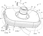
- FIG. 1 is a perspective view showing a main part of a wire harness provided with a grommet according to the first embodiment.
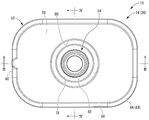
- FIG. 2 is a plan view of the grommet shown in FIG.
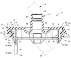
- FIG. 3 is a cross-sectional view taken along the line III-III in FIG.
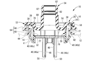
- FIG. 4 is a sectional view taken along line IV-IV in FIG.
- FIG. 5 is an exploded perspective view of the grommet shown in FIG.
- FIG. 6 is a perspective view from the bottom surface side of the grommet member constituting the grommet shown in FIG.
- FIG. 7 is a view showing a state in which the guide portion slides with respect to the inner wall of the through hole of the vehicle body panel when the grommet shown in FIG.
- FIG. 8 is a view showing a state in which the locking portion abuts on the inner wall of the through hole of the vehicle body panel and is deformed when the grommet shown in FIG. 2 is attached to the vehicle body panel, and corresponds to FIG. It is a vertical sectional view.
- FIG. 9 is a vertical cross-sectional view showing another aspect of the grommet of the present disclosure, and is an enlarged view of a main part of the figure corresponding to FIG.
- the grommet of this disclosure is (1) A grommet that is attached to a vehicle body panel having a through hole through which an electric wire penetrates, and includes an inner member that can be locked to the vehicle body panel and a tubular grommet member that is held by the inner member.
- the grommet member includes a first tubular portion, a second tubular portion arranged on the opposite side of the first tubular portion, and an annular waterproof lip provided on the first tubular portion and capable of contacting the vehicle body panel.
- the inner member has an annular main body portion assembled inside the first tubular portion of the grommet member, and is slidable with respect to the inner wall of the through hole while projecting from the main body portion.
- the guide portion has a guide portion, and the guide portion projects from the water-stopping lip in a direction opposite to that of the second cylinder portion in a state where the inner member is assembled to the first cylinder portion.
- the inner member has a guide portion that protrudes in the direction opposite to the second cylinder portion of the grommet member from the main body portion of the inner member and the waterproof lip of the grommet member. Therefore, the work of attaching the grommet to the vehicle body panel can be performed while sliding the guide portion of the inner member on the inner wall of the through hole of the vehicle body panel.
- the grommet can be attached to the through hole of the vehicle body panel while the entire grommet is held in the correct direction with respect to the vehicle body panel including the through hole, and the grommet may be attached at an angle with respect to the vehicle body panel. Can be reduced. As a result, it is possible to reduce or suppress the occurrence of a problem that a gap is generated between the waterproof lip of the grommet member and the vehicle body panel, and it is possible to advantageously improve the sealing property of the grommet.
- the inner member further has a plurality of locking portions that can be locked to the vehicle body panel, the plurality of locking portions include a first locking portion, and the guide portion is a first guide. It is preferable that the first guide portion and the second guide portion are provided on both sides of the first locking portion in the circumferential direction of the main body portion, including the portion and the second guide portion. Two guide portions including a first guide portion and a second guide portion are provided on both sides in the circumferential direction of the first locking portion, and are provided so as to sandwich the first locking portion. Therefore, the sliding of the two-point contact by the two guide portions makes it possible to hold the grommet in the correct direction with respect to the vehicle body panel more stably, and the sealing property of the grommet can be further improved.
- the first tubular portion of the grommet member further has a positioning concave portion
- the main body portion of the inner member further has a positioning convex portion that fits into the positioning concave portion
- the guide portion protrudes. It is preferable that the positioning convex portion is arranged on the same side as the guide portion in the main body portion when viewed from the first direction along the direction of the grommet.
- a positioning convex portion and a positioning concave portion are provided between the facing surfaces of the grommet member and the inner member, so that the risk of erroneous assembly in which the inner member is assembled in a direction different from the normal position with respect to the grommet member can be reduced. Because it can be done.
- the operator when assembling the inner member to the grommet member, the operator will assemble the inner member to the grommet member while holding the portion opposite to the positioning convex portion. Therefore, since the positioning convex portion is provided on the same side as the guide portion, it is possible to prevent the guide member from interfering with the inner member when the operator holds the inner member, and to improve workability. ..
- the positioning convex portion is provided on the same side as the guide portion in the main body portion
- the positioning convex portion is provided in the half-circumferential portion in which the guide portion is arranged in the center in the circumferential direction of the main body portion.
- the operator when assembling the inner member to the grommet member, the operator will assemble the inner member to the grommet member while holding the portion opposite to the positioning recess. Therefore, since the positioning recess is provided on the same side as the guide portion, it is possible to prevent the guide member from interfering with the inner member when the operator holds the inner member, and to improve workability.
- the positioning recess is provided on the same side as the guide portion in the main body portion.
- the positioning recess is provided in the half-circumferential portion in which the guide portion is arranged in the center in the circumferential direction of the main body portion.
- the guide portion is provided at the same position as or outside the inner peripheral surface of the main body portion. This is because the guide portion does not protrude inward in the radial direction of the inner member from the inner peripheral surface of the main body portion, which is the penetrating region of the electric wire, so that the possibility of interference between the electric wire and the guide portion is advantageously reduced.
- the wire harness of the present disclosure is (6) A wire harness including the grommet according to any one of (1) to (5) above and an electric wire penetrating the grommet.
- the wire harness of the present disclosure it is possible to provide a wire harness having the grommet according to any one of the above (1) to (5), and any one of the above (1) to (5). It is possible to obtain the same action and effect as the grommet described in 1.
- the electric wire is wired in a direction different from the direction in which the guide portion is provided. This is because the guide portion is not provided in the wiring direction of the electric wire, so that the interference between the guide portion and the electric wire can be suppressed or reduced.
- the wire harness 10 includes a grommet 16 attached to the through hole 14 of the vehicle body panel 12 and an electric wire 18 penetrating the grommet 16.
- the vertical direction means the vertical direction in FIG.
- the left-right direction means the left-right direction in FIG.
- the front-back direction means the up-down direction in FIG.
- these directions do not always coincide with the directions of the wire harness 10 and the grommet 16 when the vehicle is mounted.
- the electric wires 18 are arranged through the through holes 14 of the vehicle body panel 12 that separates the interior of the vehicle from the outside of the vehicle.
- the electric wire 18 constituting the wire harness 10 is provided so as to straddle the inside of the vehicle and the outside of the vehicle.
- the grommet 16 is attached to the electric wire 18 in an extrapolated state. By attaching the grommet 16 to the vehicle body panel 12, the electric wire 18 extends across the interior and exterior of the vehicle while being inserted through the grommet 16.
- the vehicle body panel 12 has a substantially flat plate shape.
- the vehicle body panel 12 is formed with a through hole 14 having a substantially oval shape or a substantially rounded rectangular shape, which is larger in the left-right direction than in the front-rear direction.
- the peripheral edge of the opening of the through hole 14 gradually rises from the inside of the vehicle toward the outside of the vehicle. That is, the inner diameter of the through hole 14 gradually decreases from the inside of the vehicle to the outside of the vehicle.
- the electric wire 18 is a coated electric wire in which the core wire 20 is covered with an insulating layer 22 made of a material having an insulating property such as synthetic resin.
- the upper part is the inside of the vehicle and the lower part is the outside of the vehicle with the vehicle body panel 12 in between.
- the grommet 16 liquidally covers the through hole 14 of the vehicle body panel 12.
- the grommet 16 prevents water and noise from entering the vehicle interior from the outside of the vehicle interior, for example.
- the grommet 16 includes an inner member 24 that can be locked to the vehicle body panel 12, and a substantially cylindrical grommet member 26 that is held by the inner member 24.
- the inner member 24 is a substantially annular member as a whole. That is, the inner member 24 includes a main body portion 28 having a substantially annular peripheral wall 27. Further, the inner member 24 can be preferably formed of, for example, a hard synthetic resin.
- the outer shape of the main body 28 is a substantially rounded rectangular shape in a plan view. That is, the main body 28 has a smaller front-rear dimension (that is, a left-right dimension in FIG. 4) than a left-right dimension (that is, a left-right dimension in FIG. 3).
- the main body 28 is formed in a size smaller than that of the through hole 14. As a result, the entire main body 28 can be inserted through the through hole 14.
- the main body 28 has a predetermined vertical dimension.
- a substantially annular outer peripheral flange portion 30 that extends outward is provided at the upper end of the main body portion 28.
- a substantially annular inner peripheral flange portion 32 extending inward is provided at the lower end of the main body portion 28.
- a lightening hole 34 that opens upward and extends in the circumferential direction is provided on the upper surface of the outer peripheral flange portion 30.
- four lightening holes 34 are formed.
- the outer diameter of the outer peripheral flange portion 30 is formed to be larger than the inner diameter of the through hole 14 in the vehicle body panel 12.
- the outer peripheral flange portion 30 is formed with a positioning convex portion 36 projecting outward in a part in the circumferential direction.
- the substantially polygonal positioning convex portion 36 projects to the left from the outer peripheral surface of the outer peripheral flange portion 30.
- the positioning convex portion 36 gradually becomes narrower toward the left, which is the protruding direction.
- the outer peripheral flange portion 30 is formed with a through window 38 that penetrates in the vertical direction.
- the inner peripheral surface of the peripheral wall 27 protrudes inward from the other portions.
- the through window 38 is formed not only on the outer peripheral flange portion 30 but also on the peripheral wall 27.
- the through window 38 is formed with a predetermined width dimension.
- the outer peripheral surface of the peripheral wall 27 (that is, the radial inward surface on the inner surface of the through window 38) is located inside the other portion.
- a total of four through windows 38 having a substantially rectangular shape in a plan view are provided on both sides in the left-right direction and both sides in the front-rear direction.
- the lower end of the peripheral wall 27 is located below the other parts.
- a locking portion 40 is provided so as to be folded outward and project diagonally upward. That is, the peripheral wall 27 and the protruding tip of the locking portion 40 are separated from each other at a predetermined distance in the horizontal direction (directions orthogonal to the vertical direction, for example, the horizontal direction and the front-rear direction). As a result, the locking portion 40 can be elastically deformed in the direction of approaching or separating from the peripheral wall 27.
- the locking portion 40 is provided at a position corresponding to the formation position of each through window 38.
- first locking portion 40a and the second locking portion 40b are provided so as to face each other in the left-right direction. Further, a third locking portion 40c and a fourth locking portion 40d are provided so as to face each other in the front-rear direction.
- the outer surface of the locking portion 40 is an inclined surface 41 that inclines outward as it goes upward. Further, in the initial state before the grommet 16 is attached to the through hole 14 of the vehicle body panel 12, a contact surface 42 inclined in the horizontal direction is provided at the protruding tip of the locking portion 40 from the upper end of the inclined surface 41. It is provided continuously. Further, inside the contact surface 42, a protruding portion 44 projecting substantially upward is provided.
- the inner member 24 is provided with a guide portion 46 projecting downward from the main body portion 28.
- the guide portion 46 has a substantially rectangular plate shape having a thickness dimension substantially equal to that of the peripheral wall 27. Further, the guide portion 46 continuously extends downward from the lower end of the peripheral wall 27.
- the guide portion 46 is provided in a part of the peripheral wall 27 in the circumferential direction. That is, the guide portion 46 is provided at a position corresponding to the through window 38 formed in the outer peripheral flange portion 30.
- the guide portion 46 is provided on the left side. Therefore, when viewed from the first direction (direction from upward to downward) along the direction in which the guide portion 46 protrudes, the positioning convex portion 36 and the guide portion 46 are at substantially the same position (left) in the circumferential direction. ..
- the outer surface of the guide portion 46 is a flat surface that extends in the vertical direction.
- the outer surface of the guide portion 46 is continuous with the outer peripheral surface of the peripheral wall 27 without any step.
- a rib 48 projecting inward is provided on the inner surface of the guide portion 46.
- the inwardly protruding tip surface of the rib 48 is located at a horizontal position substantially equal to the inwardly protruding tip surface of the inner peripheral flange portion 32 provided at the lower end of the peripheral wall 27. That is, the inner surface of the rib 48 is continuous with the inner surface of the inner peripheral flange portion 32 without a substantially step.
- the inclined curved surface 50 is provided on the lower end surface of the rib 48.
- the inner surface of the guide portion 46 is located at a position substantially equal to the inner surface of the peripheral wall 27 or outside the inner surface of the peripheral wall 27 at the formation position of the through window 38 when considering without including the rib 48. .. Further, even when the rib 48 is included, the inner surface of the guide portion 46 (protruding tip surface of the rib 48) is at a position substantially equal to the inner surface (protruding tip surface) of the inner peripheral flange portion 32.
- the inner surface of the guide portion 46 is provided at the same position as or outside the inner peripheral surface of the main body portion 28 in the radial direction (horizontal direction, for example, the left-right direction) of the inner member 24. Has been done. In other words, the inner surface of the guide portion 46 is provided so as not to protrude inward in the radial direction from the inner peripheral surface of the main body portion 28.
- a plurality of guide portions 46 are provided. That is, on the left side, the first guide portion 46a and the second guide portion 46b are provided so as to face each other in the circumferential direction of the inner member 24 (main body portion 28).
- the above-mentioned first locking portion 40a is provided between the first guide portion 46a and the second guide portion 46b facing each other.
- the first guide portion 46a and the second guide portion 46b are provided on both sides of the first locking portion 40a in the circumferential direction of the main body portion 28. Therefore, in the first embodiment, the first and second guide portions 46a and 46b and the first locking portion 40a are provided at substantially equal positions in the circumferential direction of the main body portion 28.
- first and second guide portions 46a and 46b and the second locking portion 40b are provided at positions facing each other in the radial direction (left-right direction). Further, the first and second guide portions 46a and 46b and the third and fourth locking portions 40c and 40d have a central angle of approximately 90 degrees in the circumferential direction of the main body portion 28 (approximately 1/4 circumferential circumferential direction). Separated (by length).
- the grommet member 26 has a substantially stepped tubular shape as a whole, and can be preferably formed by an elastic body such as rubber or an elastomer. That is, the grommet member 26 includes a first tubular portion 52 having a relatively large diameter and located downward, and a second tubular portion 54 having a substantially cylindrical shape having a smaller diameter and projecting upward from the first tubular portion 52. ing. Therefore, in the grommet member 26, the first cylinder portion 52 and the second cylinder portion 54 are provided on opposite sides of each other in the vertical direction.
- the first tubular portion 52 has a substantially oval shape or a substantially rounded rectangular shape in a plan view.
- the upper opening of the first tubular portion 52 is partially covered with an annular upper bottom wall portion 56 having a substantially oval shape or a substantially rounded rectangular shape in a plan view and extending in the horizontal direction.
- a tubular wall portion 58 projecting downward is provided on the outer peripheral edge portion of the upper bottom wall portion 56.
- the first tubular portion 52 is configured including the upper bottom wall portion 56 and the tubular wall portion 58.
- a part of the tubular wall portion 58 in the circumferential direction is provided with an outward protruding portion 60 projecting outward.
- the outward protrusion 60 is provided on the left side.
- a positioning recess 62 that opens inward is formed inside the outward protrusion 60.
- the outward protrusion 60 and the positioning recess 62 have the same shape as the positioning protrusion 36 in the inner member 24. That is, it is a polygonal shape in which the plan view or the projection view from above of the outward protrusion 60 and the positioning recess 62 gradually narrows toward the left.
- a substantially annular annular wall portion 64 extending continuously over the entire circumference in the circumferential direction is connected to the lower end of the tubular wall portion 58.
- the annular wall portion 64 has the same shape as the first tubular portion 52. That is, the outer shape of the annular wall portion 64 has a substantially oval shape or a substantially rounded rectangular shape in a plan view.
- the outer diameter of the annular wall portion 64 is larger than the outer diameter of the tubular wall portion 58.
- the inner diameter dimension of the annular wall portion 64 is smaller than the inner diameter dimension of the cylinder wall portion 58.
- the annular wall portion 64 has a certain radial width dimension.
- the annular wall portion 64 extends in a substantially horizontal direction.
- the lower end of the tubular wall portion 58 is connected to the radial intermediate portion of the annular wall portion 64.
- the outer peripheral side of the annular wall portion 64 with respect to the connecting portion with the tubular wall portion 58 is the annular outer wall portion 66 protruding outward from the tubular wall portion 58.
- the inner peripheral side of the annular wall portion 64 with respect to the connecting portion with the tubular wall portion 58 is the annular inner side wall portion 68 protruding inward from the tubular wall portion 58.
- the outer peripheral portion of the upper bottom wall portion 56 and the inner side wall portion 68 face each other in the vertical direction.
- the outer peripheral edges of the upper bottom wall portion 56 and the inner side wall portion 68 are connected to each other by the tubular wall portion 58.
- the locking portion is formed between the water blocking lip 72 and the peripheral wall 27 in the horizontal direction at the forming position of the locking portion 40.
- the protruding portion 44 protruding upward is inserted.
- the waterproof lip 72 protrudes in the vertical direction so as not to reach the contact surface 42 of the locking portion 40. It protrudes downward with dimensions.
- the waterproof lip 72 does not reach the lower end of the main body 28. That is, the water stop lip 72 is located above the lower end of the guide portion 46. In other words, in the state where the inner member 24 and the grommet member 26 are assembled, the guide portion 46 projects below the water stop lip 72.
- annular first lip 74a and a second lip 74b that are separated from each other in the radial direction are provided.
- annular recess 76 that opens downward is provided between the first lip 74a and the second lip 74b in the radial direction.
- the annular recess 76 allows the first lip 74a and the second lip 74b to be deformed when the grommet 16 is attached to the vehicle body panel 12.
- the first and second lips 74a and 74b and the peripheral edge portion of the through hole 14 in the vehicle body panel 12 are easily brought into close contact with each other, and the water stopping effect of the water stopping lip 72 can be improved.
- the second cylinder portion 54 is located substantially in the center of the first cylinder portion 52 in a plan view. That is, the inner peripheral edge portion of the upper bottom wall portion 56 and the lower end portion of the second cylinder portion 54 are connected by an annular connecting portion 78.
- the connecting portion 78 has a substantially semicircular shape that opens upward in the vertical cross section shown in FIG. 3 and the like. Then, the inner peripheral edge portion of the upper bottom wall portion 56 and the lower end portion of the second cylinder portion 54 are connected by the connecting portion 78, so that an annular recess 80 that opens upward is formed around the second cylinder portion 54. It is formed.
- the protruding direction of the second tubular portion 54 can be adjusted with the deformation of the connecting portion 78, and the degree of freedom in the wiring direction of the electric wire 18 inserted through the second tubular portion 54 can be improved.
- the inner peripheral surface of the second tubular portion 54 is provided with a small diameter portion 82 that protrudes toward the inner peripheral side and has a reduced inner diameter.
- a plurality of small diameter portions 82 are provided so as to be separated from each other in the vertical direction. That is, the risk of the electric wire 18 being pulled out from the second tubular portion 54 can be reduced by contacting the electric wire 18 inserted through the second tubular portion 54 so that the small diameter portion 82 bites into the electric wire 18.
- the second cylinder portion 54 may be replaced with the electric wire 18 by the small diameter portion 82 as described above, for example, by wrapping an adhesive tape or the like from the outer peripheral surface of the electric wire 18 to the outer peripheral surface of the second cylinder portion 54, the second cylinder portion 54 The extraction of the electric wire 18 from the wire 18 may be suppressed.
- the inner member 24 and the grommet member 26 are assembled to each other. Specifically, for example, while holding the grommet member 26 with one hand and looking into the positioning recess 62 from the bottom surface side, the positioning protrusion 36 of the inner member 24 is inserted into the positioning recess 62 and fitted. Then, it is inserted into the accommodating area 70 of the grommet member 26 so as to cover the outer peripheral flange portion 30 of the inner member 24. As a result, the main body 28 of the inner member 24 is assembled inside the first cylinder 52 of the grommet member 26.
- the electric wire 18 is inserted through the second cylinder portion 54 of the grommet member 26 to which the inner member 24 is assembled. As a result, the wire harness 10 is completed.
- An adhesive tape or the like may be wound from the outer peripheral surface of the electric wire 18 to the outer peripheral surface of the second cylinder portion 54.
- the portion of the electric wire 18 projecting downward from the second tubular portion 54 is wired in a direction different from the direction in which the guide portion 46 is provided (for example, to the right). Further, the portion of the electric wire 18 that protrudes upward from the second cylinder portion 54 can be wired in any direction by adjusting the protruding direction of the second cylinder portion 54 as described above.
- the grommet 16 is tilted with or without inward deformation of the locking portion 40 (for example, the first locking portion 40a).
- the central axis L1 of the grommet 16 and the central axis L2 of the through hole 14 are aligned with each other.
- all of the first to fourth locking portions 40a to 40d are in contact with the inner wall (inner peripheral edge portion) of the through hole 14.
- the first to fourth locking portions 40a to 40d all come into contact with the inner wall of the through hole 14, and the first to fourth locking portions 40a to 40d come into contact with each other.
- the first to fourth locking portions 40a to 40d are elastically deformed inward.
- the locking portion 40 is elastically restored and deformed, and as shown in FIG.
- the contact surfaces 42 of the locking portions 40 come into contact with each other.
- the locking portions 40 (first to fourth locking portions 40a to 40d) in the inner member 24 are locked to the inner wall (inner peripheral edge portion) of the through hole 14.
- the inner peripheral surface of the through hole 14 and the contact surface 42 are in contact with each other in a surface contact state.
- the possibility that the locking portions 40 (first to fourth locking portions 40a to 40d) are unintentionally released from the inner wall (inner peripheral edge portion) of the through hole 14 can be reduced.
- the deformation of the locking portions 40 (first to fourth locking portions 40a to 40d) in the restoration direction is restricted by the inner wall (inner peripheral edge portion) of the through hole 14 and the protruding portion 44 coming into contact with each other. Will be done. This completes the attachment of the wire harness 10 to the through hole 14 of the vehicle body panel 12.
- the water stop lip 72 abuts on the peripheral edge of the through hole 14 in the vehicle body panel 12 and is pressed upward.
- the first and second lips 74a and 74b are in close contact with the peripheral edge of the through hole 14.
- the inside and outside of the vehicle interior are liquid-tightly blocked by the waterproof lip 72, and the intrusion of water, noise, etc. from the outside of the vehicle interior into the vehicle interior is suppressed.
- the locking portions 40 are elastically restored and deformed, and the sound and feel of the inner wall (inner peripheral edge portion) of the through hole 14 and the protruding portion 44 hitting each other. The operator may be able to grasp the completion of the installation.
- the wire harness 10 when removing the wire harness 10 from the through hole 14 of the vehicle body panel 12, after pushing the wire harness 10 toward the outside of the vehicle interior (downward in FIG. 3 and the like), the wire harness 10 is pushed through the water stop lip 72 or the water stop lip. By directly pressing the protruding portion 44 in the locking portion 40 (first to fourth locking portions 40a to 40d) inward without going through the 72, the locking portion 40 (first to fourth locking portions) The lock on the vehicle body panel 12 of 40a to 40d) is released. By pulling out the wire harness 10 toward the vehicle interior (upward) in this state, the wire harness 10 can be removed from the through hole 14 of the vehicle body panel 12.
- the guide portion 46 (first guide portion 46a and second guide portion 46b) protruding downward from the grommet 16
- the grommet 16 By sliding the inner wall (inner peripheral edge) of the through hole 14, the grommet 16 is straightened with respect to the through hole 14 (in a state where the central axis L1 of the grommet 16 and the central axis L2 of the through hole 14 are parallel).
- the annular waterproof lip 72 can be stably brought into close contact with the peripheral edge of the through hole 14 over the entire circumference, and the sealing property can be improved.
- first guide portion 46a and second guide portion 46b are provided, and the contact area between the outer surface of the guide portion 46 and the inner wall (inner peripheral wall portion) of the through hole 14 is provided. Can be increased, so that the guide effect of the guide portion 46 can be more stably exhibited.
- first locking portion 40a is provided between the first guide portion 46a and the second guide portion 46b, the inclined surface 41 of the first locking portion 40a and the inner wall (inner peripheral wall) of the through hole 14 are provided.
- the central axis L1 of the grommet 16 and the central axis L2 of the through hole 14 are aligned with each other by the inclined surface 41 of the first locking portion 40a. ) Can also be exhibited stably.
- the inner member 24 and the grommet member 26 are provided with the positioning convex portion 36 and the positioning concave portion 62, respectively, the inner member 24 and the grommet member 26 are assembled in a desired circumferential direction. It can be easy to attach. Since both the inner member 24 and the grommet member 26 have a substantially oval shape or a substantially rounded rectangular shape, a certain degree of circumferential alignment effect is exhibited, but as in the first embodiment, they are mutually aligned. By providing the positioning convex portion 36 and the positioning concave portion 62 to be fitted, a higher alignment effect can be exhibited.
- the positioning convex portion 36 and the guide portion 46 are provided at substantially the same positions in the circumferential direction (left side in FIG. 3), for example, the grommet When inserting the positioning convex portion 36 while visually recognizing the positioning concave portion 62 of the member 26, the possibility that the visibility of the positioning convex portion 36 and the positioning concave portion 62 is deteriorated by the guide portion 46 can be reduced.
- the inner surface of the guide portion 46 (the first guide portion 46a and the second guide portion 46b) is at the same position or more in the horizontal direction as the inner peripheral surface of the main body portion 28 of the inner member 24.
- the portion of the electric wire 18 protruding downward from the second cylinder portion 54 is wired in a direction different from that of the guide portion 46 (the first guide portion 46a and the second guide portion 46b). It is possible to reduce the possibility that the wiring direction of the electric wire 18 is restricted by the guide portion 46 and that the guide portion 46 and the electric wire 18 come into contact with each other to damage the electric wire 18.
- the positioning convex portion 36 is provided on the inner member 24 and the positioning concave portion 62 is provided on the grommet member 26.
- the positioning convex portion 92 is provided. May be provided in the grommet member 94, and the positioning recess 96 may be provided in the inner member 98.
- FIG. 9 is an enlarged view of a portion corresponding to the left side of FIG. 3 in the embodiment.
- the structures other than the positioning convex portion and the positioning concave portion are the same as those in the above-described embodiment, but since the positioning convex portion 36 and the positioning concave portion 62 projecting outward are not provided, the grommet member 26 is outside.
- the direction protrusion 60 is also not provided. That is, also in this embodiment, the positioning convex portion 92 and the guide portion 46 (the first guide portion 46a and the second guide portion 46b) are provided at substantially the same position (left side) in the circumferential direction.
- the positioning protrusions 36, 92 and the positioning recesses 62, 96 are formed on the outer peripheral surface of the outer peripheral flange portion 30 of the inner members 24, 98 and the cylinder of the grommet members 26, 94. It was provided on the overlapping surface of the wall portion 58 (outward protruding portion 60) with the inner peripheral surface.
- the present invention is not limited to this embodiment, and the positioning convex portion and the positioning concave portion are, for example, the overlapping surface of the upper surface of the outer peripheral flange portion and the upper bottom wall portion of the grommet member, or the lower surface of the outer peripheral flange portion and the grommet member. It may be provided on the overlapping surface with the inner side wall portion.
- the number of locking portions locked to the vehicle body panel is not limited, but it is preferable to provide a plurality of locking portions.
- a plurality of locking portions it is preferable that the plurality of locking portions are provided at substantially equal intervals in the circumferential direction of the inner member.
- the shape of the through hole in the grommet (grommet member and inner member) and the vehicle body panel is not limited, and in addition to the substantially oval shape or the substantially rounded rectangular shape as in the above embodiment, a perfect circle or an ellipse, It may have a polygonal shape or the like.
- the number, shape, position, etc. of the guide portions are not limited.
- the guide portions 46 (first guide portion 46a and second guide portion 46b) are provided at one location (left side in FIG. 3) in the circumferential direction of the inner member 24, but a plurality of guide portions 46 in the circumferential direction are provided. It may be provided at a location.
- the guide portion 46 (first guide portion 46a and second guide portion 46b) and the locking portion 40 (first locking portion 40a) are provided at substantially the same positions in the circumferential direction.
- the guide portion and the locking portion may be provided at different positions in the circumferential direction.
- the rib protruding inward in the guide portion is not indispensable.
Landscapes
- Engineering & Computer Science (AREA)
- Architecture (AREA)
- Civil Engineering (AREA)
- Structural Engineering (AREA)
- General Engineering & Computer Science (AREA)
- Mechanical Engineering (AREA)
- Insulating Bodies (AREA)
- Installation Of Indoor Wiring (AREA)
- Insulated Conductors (AREA)
Abstract
車体パネルの貫通孔に安定して装着することができ、シール性の低下を抑えることができる、新規な構造のグロメットを提供する。 グロメット16であって、車体パネル12に係止可能なインナー部材24と、インナー部材24に保持される筒状のグロメット部材26と、を備え、グロメット部材26は、第1筒部52と、第1筒部52と反対側に配置される第2筒部54と、第1筒部52に設けられ車体パネル12と接触可能な環状の止水リップ72と、を有し、インナー部材24は、グロメット部材26の第1筒部52の内側に組み付けられる環状の本体部28と、本体部28から突出するとともに貫通孔14の内壁に対して摺動可能であるガイド部46を有し、ガイド部46は、インナー部材24が第1筒部52に組み付けられた状態において、止水リップ72よりも第2筒部54とは反対方向に突出している。
Description
本開示は、グロメットおよびワイヤハーネスに関する。
従来から、ワイヤハーネス等の電線部材を自動車の車室外から車室内へ配索する際に、ワイヤハーネスにグロメットを装着し、グロメットを車室内外を仕切る車体パネルに形成された貫通孔に取り付けている。グロメットは、貫通孔を塞ぐことで、車室外から車室内に水や騒音等が浸入することを防止している。
近年では、特許文献1に示されるように、弾性材料により形成されるグロメット部材と、樹脂材料により形成されるインナー部材とを備えるグロメットが用いられている。このようなグロメットでは、インナー部材を車体パネルの貫通孔の縁部に係止させることで、グロメット部材に設けられた止水リップを車体パネルに密着させることができる。
しかしながら、従来のグロメット部材とインナー部材を備えるグロメットでは、貫通孔へ装着する際に、グロメットが車体パネルに対して傾斜等して、不完全な装着状態となる場合があった。その結果、グロメット部材の止水リップと車体パネルとの間に隙間が生じてグロメットのシール性が低下するおそれがあった。
本開示は、上述の事情を背景に為されたものであって、その解決課題は、車体パネルの貫通孔に安定して装着することができ、シール性の低下を抑えることができる、新規な構造のグロメットおよびワイヤハーネスを提供することにある。
本開示のグロメットは、電線が貫通する貫通孔を有する車体パネルに取り付けられるグロメットであって、前記車体パネルに係止可能なインナー部材と、前記インナー部材に保持される筒状のグロメット部材と、を備え、前記グロメット部材は、第1筒部と、前記第1筒部と反対側に配置される第2筒部と、前記第1筒部に設けられ前記車体パネルと接触可能な環状の止水リップと、を有し、前記インナー部材は、前記グロメット部材の前記第1筒部の内側に組み付けられる環状の本体部と、前記本体部から突出するとともに前記貫通孔の内壁に対して摺動可能であるガイド部を有し、前記ガイド部は、前記インナー部材が前記第1筒部に組み付けられた状態において、前記止水リップよりも前記第2筒部とは反対方向に突出しているものである。
また、本開示のワイヤハーネスは、本開示に係るグロメットと、前記グロメットを貫通する電線と、を備えるものである。
本開示によれば、車体パネルの貫通孔に安定して装着することができ、シール性の低下を抑えることができる、新規な構造のグロメットおよびワイヤハーネスを提供することができる。
<本開示の実施形態の説明>
最初に、本開示の実施態様を列記して説明する。
本開示のグロメットは、
(1)電線が貫通する貫通孔を有する車体パネルに取り付けられるグロメットであって、前記車体パネルに係止可能なインナー部材と、前記インナー部材に保持される筒状のグロメット部材と、を備え、前記グロメット部材は、第1筒部と、前記第1筒部と反対側に配置される第2筒部と、前記第1筒部に設けられ前記車体パネルと接触可能な環状の止水リップと、を有し、前記インナー部材は、前記グロメット部材の前記第1筒部の内側に組み付けられる環状の本体部と、前記本体部から突出するとともに前記貫通孔の内壁に対して摺動可能であるガイド部を有し、前記ガイド部は、前記インナー部材が前記第1筒部に組み付けられた状態において、前記止水リップよりも前記第2筒部とは反対方向に突出しているものである。
最初に、本開示の実施態様を列記して説明する。
本開示のグロメットは、
(1)電線が貫通する貫通孔を有する車体パネルに取り付けられるグロメットであって、前記車体パネルに係止可能なインナー部材と、前記インナー部材に保持される筒状のグロメット部材と、を備え、前記グロメット部材は、第1筒部と、前記第1筒部と反対側に配置される第2筒部と、前記第1筒部に設けられ前記車体パネルと接触可能な環状の止水リップと、を有し、前記インナー部材は、前記グロメット部材の前記第1筒部の内側に組み付けられる環状の本体部と、前記本体部から突出するとともに前記貫通孔の内壁に対して摺動可能であるガイド部を有し、前記ガイド部は、前記インナー部材が前記第1筒部に組み付けられた状態において、前記止水リップよりも前記第2筒部とは反対方向に突出しているものである。
本開示のグロメットによれば、インナー部材が、インナー部材の本体部やグロメット部材の止水リップよりも、グロメット部材の第2筒部とは反対方向に突出するガイド部を有している。それゆえ、グロメットの車体パネルへの取付作業を、インナー部材のガイド部を車体パネルの貫通孔の内壁に摺動させつつ行うことができる。これにより、グロメット全体を貫通孔を含む車体パネルに対して正しい向きに保持した状態で、グロメットを車体パネルの貫通孔に取り付けることができ、グロメットが車体パネルに対して傾斜して取り付けられるおそれを低減することができる。その結果、グロメット部材の止水リップと車体パネルとの間に隙間が生じる不具合の発生を低減または抑制でき、グロメットのシール性を有利に向上することができる。
(2)前記インナー部材は、前記車体パネルに係止可能な複数の係止部をさらに有し、前記複数の係止部は、第1係止部を含み、前記ガイド部は、第1ガイド部と、第2ガイド部とを含み、前記第1ガイド部と前記第2ガイド部とは、前記本体部の周方向において前記第1係止部の両側に設けられている、ことが好ましい。第1ガイド部と第2ガイド部からなる2本のガイド部が、第1係止部の周方向両側に設けられ、第1係止部を挟む様に設けられている。それ故、2本のガイド部による2点接触の摺動により、一層安定してグロメットを車体パネルに対する正しい向きに保持することができ、グロメットのシール性を一層有利に向上できる。
(3)前記グロメット部材の前記第1筒部は、位置決め凹部をさらに有し、前記インナー部材の前記本体部は、前記位置決め凹部に嵌合する位置決め凸部をさらに有し、前記ガイド部が突出する方向に沿う第1方向からみた場合に、前記位置決め凸部は、前記本体部において前記ガイド部と同じ側に配置されている、ことが好ましい。グロメット部材とインナー部材の対向面間に位置決め凸部と位置決め凹部が設けられており、グロメット部材に対してインナー部材が正規位置とは異なる向きで組み付けられる誤組み付けが発生するおそれを低減することができるからである。加えて、インナー部材をグロメット部材に組み付ける際には、作業者が位置決め凸部と反対側の部分を保持しながら、グロメット部材に組み付けることとなる。それゆえ、位置決め凸部がガイド部と同じ側に設けられていることにより、作業者がインナー部材を保持する際にガイド部材が干渉することが抑えられて、作業性の向上を図ることができる。
なお、「位置決め凸部が本体部においてガイド部と同じ側に設けられている」とは、本体部の周方向で中央にガイド部を配置した半周部分に位置決め凸部が設けられていることをいう。
(4)上記(1)または(2)において、前記グロメット部材の前記第1筒部は、位置決め凸部をさらに有し、前記インナー部材の前記本体部は、前記位置決め凸部に嵌合する位置決め凹部をさらに有し、前記ガイド部から突出する方向に沿う第1方向からみて、前記位置決め凹部は、前記本体部において前記ガイド部と同じ側に配置されている、ことが好ましい。グロメット部材とインナー部材の対向面間に位置決め凸部と位置決め凹部が設けられており、グロメット部材に対してインナー部材が正規位置とは異なる向きで組み付けられる誤組み付けが発生するおそれを低減することができるからである。加えて、インナー部材をグロメット部材に組み付ける際には、作業者が位置決め凹部と反対側の部分を保持しながら、グロメット部材に組み付けることとなる。それゆえ、位置決め凹部がガイド部と同じ側に設けられていることにより、作業者がインナー部材を保持する際にガイド部材が干渉することが抑えられて、作業性の向上を図ることができる。
なお、「位置決め凹部が本体部においてガイド部と同じ側に設けられている」とは、本体部の周方向で中央にガイド部を配置した半周部分に位置決め凹部が設けられていることをいう。
(5)前記インナー部材の径方向において、前記ガイド部は、前記本体部の内周面と同じ位置またはそれよりも外側に設けられている、ことが好ましい。電線の貫通領域である本体部の内周面よりもインナー部材の径方向内方側にガイド部が突出していないことにより、電線とガイド部が干渉するおそれが有利に低減されるからである。
また、本開示のワイヤハーネスは、
(6)上記(1)から(5)のいずれか1つに記載のグロメットと、前記グロメットを貫通する電線と、を備えるワイヤハーネスである。
(6)上記(1)から(5)のいずれか1つに記載のグロメットと、前記グロメットを貫通する電線と、を備えるワイヤハーネスである。
本開示のワイヤハーネスによれば、上記(1)から(5)のいずれか1つに記載のグロメットを備えたワイヤハーネスを提供することができ、上記(1)から(5)のいずれか1つに記載のグロメットと同様の作用効果を奏することができる。
(7)上記(6)において、前記電線は、前記ガイド部が設けられている方向とは異なる方向に配線されている、ことが好ましい。電線の配線方向にガイド部が設けられていないことから、ガイド部と電線の干渉を抑制または低減できるからである。
<本開示の実施形態の詳細>
本開示のグロメットおよびワイヤハーネスの具体例を、以下に図面を参照しつつ説明する。なお、本開示は、これらの例示に限定されるものではなく、特許請求の範囲によって示され、特許請求の範囲と均等の意味および範囲内でのすべての変更が含まれることが意図される。
本開示のグロメットおよびワイヤハーネスの具体例を、以下に図面を参照しつつ説明する。なお、本開示は、これらの例示に限定されるものではなく、特許請求の範囲によって示され、特許請求の範囲と均等の意味および範囲内でのすべての変更が含まれることが意図される。
<実施形態1>
以下、本開示の実施形態1について、図1から図8を参照しつつ説明する。ワイヤハーネス10は、車体パネル12の貫通孔14に取り付けられるグロメット16と、当該グロメット16を貫通する電線18とを備えている。なお、以下の説明において、上下方向とは図3中の上下方向をいう。また、左右方向とは図2中の左右方向をいう。更に、前後方向とは、図2中の上下方向をいう。尤も、これらの方向は、車両の装着時におけるワイヤハーネス10やグロメット16の方向と必ずしも一致するものではない。
以下、本開示の実施形態1について、図1から図8を参照しつつ説明する。ワイヤハーネス10は、車体パネル12の貫通孔14に取り付けられるグロメット16と、当該グロメット16を貫通する電線18とを備えている。なお、以下の説明において、上下方向とは図3中の上下方向をいう。また、左右方向とは図2中の左右方向をいう。更に、前後方向とは、図2中の上下方向をいう。尤も、これらの方向は、車両の装着時におけるワイヤハーネス10やグロメット16の方向と必ずしも一致するものではない。
<ワイヤハーネス10>
電線18は、車室内と車室外を仕切る車体パネル12の貫通孔14を貫通して配索されている。換言すれば、ワイヤハーネス10を構成する電線18が、車室内と車室外に跨って設けられている。また、電線18には、グロメット16が外挿状態で装着されている。グロメット16が車体パネル12に取り付けられることで、電線18がグロメット16に挿通された状態で車室内外に跨って延びている。
電線18は、車室内と車室外を仕切る車体パネル12の貫通孔14を貫通して配索されている。換言すれば、ワイヤハーネス10を構成する電線18が、車室内と車室外に跨って設けられている。また、電線18には、グロメット16が外挿状態で装着されている。グロメット16が車体パネル12に取り付けられることで、電線18がグロメット16に挿通された状態で車室内外に跨って延びている。
実施形態1では、車体パネル12が略平板形状とされている。車体パネル12には、前後方向寸法よりも左右方向寸法の方が大きな略長円形状または略角丸矩形状の貫通孔14が形成されている。特に、実施形態1では、貫通孔14の開口周縁部が車室内から車室外に向かって次第に立ち上がっている。即ち、貫通孔14の内径寸法が、車室内から車室外に向かって次第に小さくなっている。また、電線18は、芯線20が合成樹脂等の絶縁性を有する材質からなる絶縁層22により被覆された被覆電線とされている。なお、実施形態1では、車体パネル12を挟んで上方が車室内であり、下方が車室外である。
<グロメット16>
グロメット16は、車体パネル12の貫通孔14を液密的に覆蓋している。このグロメット16により、例えば車室外から車室内への水や騒音の浸入が防止される。グロメット16は、車体パネル12に係止可能なインナー部材24と、当該インナー部材24に保持される略筒状のグロメット部材26とを備えている。
グロメット16は、車体パネル12の貫通孔14を液密的に覆蓋している。このグロメット16により、例えば車室外から車室内への水や騒音の浸入が防止される。グロメット16は、車体パネル12に係止可能なインナー部材24と、当該インナー部材24に保持される略筒状のグロメット部材26とを備えている。
<インナー部材24>
インナー部材24は、全体として略環状の部材である。即ち、インナー部材24は、略環状の周壁27を有する本体部28を備えている。また、インナー部材24は、例えば硬質の合成樹脂により好適に形成され得る。実施形態1では、本体部28の外形が、平面視において略角丸矩形状とされている。即ち、本体部28は、左右方向寸法(即ち、図3中の左右方向寸法)に対して、前後方向寸法(即ち、図4中の左右方向寸法)の方が小さくされている。本体部28は、貫通孔14よりも小さい大きさで形成されている。これにより、本体部28の全体が貫通孔14に対して挿通可能となっている。
インナー部材24は、全体として略環状の部材である。即ち、インナー部材24は、略環状の周壁27を有する本体部28を備えている。また、インナー部材24は、例えば硬質の合成樹脂により好適に形成され得る。実施形態1では、本体部28の外形が、平面視において略角丸矩形状とされている。即ち、本体部28は、左右方向寸法(即ち、図3中の左右方向寸法)に対して、前後方向寸法(即ち、図4中の左右方向寸法)の方が小さくされている。本体部28は、貫通孔14よりも小さい大きさで形成されている。これにより、本体部28の全体が貫通孔14に対して挿通可能となっている。
この本体部28は、所定の上下方向寸法を有している。本体部28の上端には、外側に広がる略環状の外周フランジ部30が設けられている。また、本体部28の下端には、内側に広がる略環状の内周フランジ部32が設けられている。実施形態1では、外周フランジ部30の上面において、上方に開口して周方向に延びる肉抜穴34が設けられている。特に、実施形態1では、4つの肉抜穴34が形成されている。なお、外周フランジ部30の外径寸法は、車体パネル12における貫通孔14の内径寸法よりも大きく形成されている。これにより、グロメット16に対して車体パネル12の貫通孔14から抜け落ちる方向(例えば、下方)への外力が及ぼされた場合でも、外周フランジ部30と貫通孔14の周縁部とが相互に当接することで、車体パネル12からグロメット16が脱落するおそれが低減されている。
さらに、外周フランジ部30には、周方向の一部において、外側に突出する位置決め凸部36が形成されている。実施形態1では、略多角形状の位置決め凸部36が、外周フランジ部30の外周面から左方に突出している。特に、実施形態1では、位置決め凸部36が、突出方向である左方に向かって次第に狭幅となっている。これにより、後述する位置決め凸部36と位置決め凹部62との嵌合において、位置決め凸部36を位置決め凹部62に嵌め入れ易くなっている。
更にまた、外周フランジ部30には、上下方向で貫通する貫通窓38が形成されている。この貫通窓38の形成位置では、周壁27の内周面が他の部分よりも内側に突出している。また、貫通窓38は、外周フランジ部30だけでなく周壁27にもかけて形成されている。これにより、貫通窓38が所定の幅寸法をもって形成されている。そして、周壁27の外周面(即ち、貫通窓38の内面における径方向内方の面)が、他の部分よりも内側に位置している。実施形態1では、平面視において略矩形状とされた貫通窓38が、左右方向両側および前後方向両側において、計4つ設けられている。
貫通窓38の形成位置において、周壁27の下端は、他の部分よりも下方に位置している。そして、周壁27における貫通窓38の形成位置の下端には、外方に折り返されるようにして斜め上方に突出する係止部40が設けられている。即ち、周壁27と係止部40の突出先端とは所定の距離をもって水平方向(上下方向に直交する方向であって、例えば左右方向や前後方向)で離隔している。これにより、係止部40が、周壁27に対して接近または離隔する方向で弾性変形可能とされている。実施形態1では、各貫通窓38の形成位置と対応する位置に係止部40が設けられている。この結果、左右方向で相互に対向して第1係止部40aと第2係止部40bが設けられている。また、前後方向で相互に対向して第3係止部40cと第4係止部40dが設けられている。
なお、実施形態1では、係止部40の外面は、上方になるにつれて外方へ傾斜する傾斜面41である。また、グロメット16が車体パネル12の貫通孔14に取り付けられる前の初期状態において、係止部40の突出先端には、水平方向に対して傾斜する当接面42が、傾斜面41の上端から連続して設けられている。また、当接面42の内側には、略上方に突出する突出部44が設けられている。
また、インナー部材24には、本体部28から下方に突出するガイド部46が設けられている。このガイド部46は、周壁27と略等しい厚さ寸法を有する略矩形板状とされている。また、ガイド部46は、周壁27の下端から連続的に下方に延びている。実施形態1では、ガイド部46が、周壁27の周方向の一部に設けられている。即ち、ガイド部46は、外周フランジ部30に形成された貫通窓38と対応する位置に設けられている。特に、実施形態1では、ガイド部46が、左方に設けられている。したがって、ガイド部46が突出する方向に沿う第1方向(上方から下方に向かう方向)から見た場合に、位置決め凸部36とガイド部46とが周方向の略同じ位置(左方)にある。
ガイド部46の外面は、上下方向に広がる平坦面である。このガイド部46の外面は、周壁27の外周面に対して略段差なく連続している。また、ガイド部46の内面には、内方に突出するリブ48が設けられている。実施形態1では、リブ48の内方への突出先端面が、周壁27の下端に設けられた内周フランジ部32の内方への突出先端面と略等しい水平方向位置にある。即ち、リブ48の内面は、内周フランジ部32の内面に対して略段差なく連続している。また、実施形態1では、リブ48の下端面に、傾斜湾曲面50が設けられている。これにより、グロメット16に電線18を挿通する際にリブ48と電線18が当接する場合にも、電線18が損傷するおそれが低減され得る。
以上のことから、ガイド部46の内面は、リブ48を含めないで考えた場合、周壁27の内面と略等しい位置にあるか、貫通窓38の形成位置における周壁27の内面よりも外側にある。また、リブ48を含めて考えた場合でも、ガイド部46の内面(リブ48の突出先端面)は、内周フランジ部32の内面(突出先端面)と略等しい位置になる。要するに、実施形態1では、インナー部材24の径方向(水平方向であって、例えば左右方向)において、ガイド部46の内面が、本体部28の内周面と同じ位置かそれよりも外側に設けられている。換言すれば、ガイド部46の内面は、本体部28の内周面よりも径方向内方に突出することなく設けられている。
実施形態1では、複数のガイド部46が設けられている。即ち、左方において、第1ガイド部46aと第2ガイド部46bとが、インナー部材24(本体部28)の周方向で相互に対向して設けられている。特に、実施形態1では、第1ガイド部46aと第2ガイド部46bの対向間に前述の第1係止部40aが設けられている。換言すれば、本体部28の周方向において第1係止部40aの両側に、第1ガイド部46aと第2ガイド部46bが設けられている。したがって、実施形態1では、第1および第2ガイド部46a,46bと第1係止部40aとが、本体部28の周方向で略等しい位置に設けられている。また、第1および第2ガイド部46a,46bと第2係止部40bとが、径方向(左右方向)で相互に対向する位置に設けられている。更に、第1および第2ガイド部46a,46bと第3,第4係止部40c,40dとが、本体部28の周方向で略90度の中心角をもって(略1/4周の周方向長さをもって)離隔している。
<グロメット部材26>
グロメット部材26は、全体として略段付きの筒形状であり、例えばゴムやエラストマ等の弾性体により好適に形成され得る。即ち、グロメット部材26は、比較的大径で下方に位置する第1筒部52と、当該第1筒部52から上方に突出する、より小径な略円筒形状の第2筒部54とを備えている。したがって、グロメット部材26では、第1筒部52と第2筒部54とが、上下方向で相互に反対側に設けられている。
グロメット部材26は、全体として略段付きの筒形状であり、例えばゴムやエラストマ等の弾性体により好適に形成され得る。即ち、グロメット部材26は、比較的大径で下方に位置する第1筒部52と、当該第1筒部52から上方に突出する、より小径な略円筒形状の第2筒部54とを備えている。したがって、グロメット部材26では、第1筒部52と第2筒部54とが、上下方向で相互に反対側に設けられている。
第1筒部52は、図2にも示されるように、平面視が略長円形状又は略角丸矩形状である。第1筒部52の上方開口部は、平面視が略長円形状または略角丸矩形状とされて水平方向に広がる環状の上底壁部56で部分的に覆われている。また、上底壁部56の外周縁部には、下方に突出する筒壁部58が設けられている。これら上底壁部56と筒壁部58とを含んで第1筒部52が構成されている。
筒壁部58の周方向の一部には、外方に突出する外方突出部60が設けられている。実施形態1では、外方突出部60が、左方に設けられている。この外方突出部60の内部には、図3や図6に示されるように、内方に開口する位置決め凹部62が形成されている。これら外方突出部60や位置決め凹部62は、インナー部材24における位置決め凸部36と同様の形状である。即ち、外方突出部60や位置決め凹部62の平面視または上方からの投影視が、左方に向かって次第に狭幅となる多角形状である。
また、筒壁部58の下端には、周方向の全周に亘って連続して延びる略環状の環状壁部64が連結されている。この環状壁部64は、第1筒部52と同様の形状である。即ち、環状壁部64の外形は、平面視が略長円形状または略角丸矩形状である。なお、環状壁部64の外径寸法は、筒壁部58の外径寸法よりも大きくされている。また、環状壁部64の内径寸法は、筒壁部58の内径寸法よりも小さくされている。これにより、環状壁部64は、ある程度の径方向幅寸法を有している。更に、環状壁部64は、略水平方向に広がっている。この環状壁部64の径方向中間部分に、筒壁部58の下端が連結されている。
すなわち、環状壁部64において筒壁部58との連結部分よりも外周側が、筒壁部58から外方に突出する環状の外側壁部66である。また、環状壁部64において筒壁部58との連結部分よりも内周側が、筒壁部58から内方に突出する環状の内側壁部68である。要するに、上底壁部56の外周部分と内側壁部68とが上下方向で対向している。そして、上底壁部56と内側壁部68のそれぞれの外周縁部が、相互に筒壁部58で連結されている。これら上底壁部56と内側壁部68と筒壁部58により、グロメット部材26の内部には、径方向内方に開口する環状の収容領域70が形成されている。前述の位置決め凹部62は、収容領域70の外周部分から連続して外方に形成されている。
さらに、第1筒部52における内側壁部68の内周縁部には、下方に突出する環状の止水リップ72が形成されている。この止水リップ72は、後述する図7に示されるように、グロメット16が車体パネル12の貫通孔14に取り付けられる前の初期状態において、下方に突出するにつれて外周側に傾斜するテーパ筒形状である。換言すれば、止水リップ72は、インナー部材24とグロメット部材26とが組み付けられた際に、本体部28の周壁27の外周面から離隔する方向に突出している。これにより、グロメット16の車体パネル12への取付時において、車体パネル12における貫通孔14の周縁部により止水リップ72が下方から押圧されることで、止水リップ72が変形し易くされている。
なお、実施形態1では、インナー部材24とグロメット部材26とが組み付けられた際に、係止部40の形成位置において、止水リップ72と周壁27との水平方向の対向面間に係止部40において上方に突出する突出部44が入り込むようになっている。そして、車体パネル12の貫通孔14に取り付けられる前のグロメット16の初期状態(図7の状態)では、止水リップ72が、上下方向において係止部40における当接面42までは至らない突出寸法をもって下方に突出している。特に、実施形態1では、止水リップ72が、本体部28の下端まで至っていない。即ち、止水リップ72は、ガイド部46の下端よりも上方に位置している。換言すれば、インナー部材24とグロメット部材26とが組み付けられた状態において、ガイド部46は、止水リップ72よりも下方まで突出している。
また、止水リップ72の下端には、径方向の内外で相互に離隔する環状の第1リップ74aおよび第2リップ74bが設けられている。更に、これら第1リップ74aと第2リップ74bとの径方向間には、下方に開口する環状凹部76が設けられている。この環状凹部76により、グロメット16が車体パネル12に取り付けられた際に、第1リップ74aと第2リップ74bの変形が許容されるようになっている。この結果、第1および第2リップ74a,74bと車体パネル12における貫通孔14の周縁部とが相互に密着し易くされて、止水リップ72による止水効果が向上され得る。
第2筒部54は、平面視において、第1筒部52の略中央に位置している。即ち、上底壁部56の内周縁部と第2筒部54の下端部とが、環状の接続部78により接続されている。この接続部78は、図3等に示す縦断面において上方に開口する略半円形状である。そして、上底壁部56の内周縁部と第2筒部54の下端部とが接続部78により接続されることで、第2筒部54の周囲には、上方に開口する環状凹部80が形成されている。これにより、接続部78の変形を伴って第2筒部54の突出方向の調整が可能であり、第2筒部54に挿通される電線18の配索方向の自由度が向上され得る。
なお、第2筒部54の内周面には、内周側に突出して内径寸法が小さくされた小径部82が設けられている。実施形態1では、複数の小径部82が、上下方向で相互に離隔して設けられている。即ち、第2筒部54に挿通される電線18に小径部82が食い込むように当接することで、第2筒部54からの電線18の抜出しのおそれが低減され得る。なお、上記の如き小径部82による電線18の保持に代えて、または加えて、例えば電線18の外周面から第2筒部54の外周面にかけて粘着テープ等を巻き付けることで、第2筒部54からの電線18の抜出しが抑えられるようになっていてもよい。
<ワイヤハーネス10の組み付け工程>
続いて、ワイヤハーネス10の組み付け工程の具体的な一例について説明する。なお、ワイヤハーネス10の組み付け工程は、以下の記載に限定されない。
続いて、ワイヤハーネス10の組み付け工程の具体的な一例について説明する。なお、ワイヤハーネス10の組み付け工程は、以下の記載に限定されない。
先ず、インナー部材24とグロメット部材26とを相互に組み付ける。具体的には、例えばグロメット部材26を片方の手で持ち、底面側から覗き込んで位置決め凹部62を視認できる状態で、位置決め凹部62にインナー部材24の位置決め凸部36を差し入れて嵌合する。そして、インナー部材24の外周フランジ部30を覆うようにグロメット部材26の収容領域70に差し入れる。これにより、グロメット部材26における第1筒部52の内側にインナー部材24の本体部28が組み付けられる。
その後、インナー部材24が組み付けられたグロメット部材26の第2筒部54に対して電線18を挿通する。これにより、ワイヤハーネス10が完成する。なお、電線18の外周面から第2筒部54の外周面にかけて粘着テープ等を巻き付けてもよい。ここで、電線18において第2筒部54から下方に突出する部分は、ガイド部46が設けられている方向とは異なる方向(例えば、右方)に配線されることが好適である。また、電線18において第2筒部54から上方に突出する部分は、上記のように第2筒部54の突出方向を調整することで、任意の方向に配線することができる。
<ワイヤハーネス10の車体パネル12への取付け>
上記の如きワイヤハーネス10を車体パネル12に取り付けるには、先ず、図7に示されるように、車体パネル12の貫通孔14にグロメット16から下方に突出するガイド部46(第1ガイド部46aおよび第2ガイド部46b)を差し入れる。その際、貫通孔14の内壁(内周縁部)に対して、第1ガイド部46aおよび第2ガイド部46bの外面を摺動させる。なお、図7に、グロメット16の中心軸(第2筒部54の中心軸)L1と、貫通孔14の中心軸L2を一点鎖線で示す。図7からも明らかなように、貫通孔14の内壁と第1ガイド部46aおよび第2ガイド部46bとが摺動している状態では、L1とL2が水平方向でずれている。
上記の如きワイヤハーネス10を車体パネル12に取り付けるには、先ず、図7に示されるように、車体パネル12の貫通孔14にグロメット16から下方に突出するガイド部46(第1ガイド部46aおよび第2ガイド部46b)を差し入れる。その際、貫通孔14の内壁(内周縁部)に対して、第1ガイド部46aおよび第2ガイド部46bの外面を摺動させる。なお、図7に、グロメット16の中心軸(第2筒部54の中心軸)L1と、貫通孔14の中心軸L2を一点鎖線で示す。図7からも明らかなように、貫通孔14の内壁と第1ガイド部46aおよび第2ガイド部46bとが摺動している状態では、L1とL2が水平方向でずれている。
そして、貫通孔14に対してグロメット16を接近させて、貫通孔14の内壁が係止部40に差し掛かると、貫通孔14の内壁と係止部40(例えば、図7中の左方の第1係止部40a)の傾斜面41とが当接して、貫通孔14の内壁は第1ガイド部46aおよび第2ガイド部46bの外面からは離隔する。即ち、図7において、貫通孔14の内壁と第1係止部40aの傾斜面41とが当接することで、貫通孔14に対してグロメット16が、図7中の右方へ変位する。その後、更に貫通孔14に対してグロメット16を接近させることで、係止部40(例えば、第1係止部40a)の内方への変形を伴いつつ、または伴うことなく、グロメット16が傾斜面41の傾斜に沿って移動して、グロメット16の中心軸L1と貫通孔14の中心軸L2とが相互に位置合わせされる。この状態では、第1~第4係止部40a~40dの何れもが貫通孔14の内壁(内周縁部)に当接している。そして、更に貫通孔14に対してグロメット16を接近させることで、図8に示されるように、第1~第4係止部40a~40dが何れも貫通孔14の内壁に当接して、第1~第4係止部40a~40dが内方へ弾性変形させられる。
その後、貫通孔14の内壁(内周縁部)が傾斜面41を乗り越えることで、係止部40が弾性的に復元変形して、図3に示されるように、貫通孔14の内周面と係止部40(第1~第4係止部40a~40d)の当接面42とが当接する。これにより、インナー部材24における係止部40(第1~第4係止部40a~40d)が貫通孔14の内壁(内周縁部)に係止される。特に、実施形態1では、貫通孔14の内周面と当接面42とが面接触の状態をもって当接している。これにより、貫通孔14の内壁(内周縁部)に対する係止部40(第1~第4係止部40a~40d)の係止が意図せず解除されるおそれが低減され得る。なお、係止部40(第1~第4係止部40a~40d)の復元方向への変形は、貫通孔14の内壁(内周縁部)と突出部44とが相互に当接することで規制される。これにより、ワイヤハーネス10の車体パネル12の貫通孔14への取付けを完了する。
この取付完了状態では、止水リップ72が車体パネル12における貫通孔14の周縁部に当接して上方へ押圧させられている。これにより、第1および第2リップ74a,74bが貫通孔14の周縁部に密着している。この結果、車室内外が、止水リップ72によって液密的に遮断されて、車室外から車室内への水や騒音等の浸入が抑えられる。なお、係止部40(第1~第4係止部40a~40d)が弾性的に復元変形して貫通孔14の内壁(内周縁部)と突出部44とが相互に打ち当たる音や感触をもって、作業者が取付けの完了を把握できるようになっていてもよい。
また、車体パネル12の貫通孔14からワイヤハーネス10を取り外す際には、ワイヤハーネス10を車室外方向(図3等の下方)へ押し込んだ後、止水リップ72を介して、または止水リップ72を介することなく直接、係止部40(第1~第4係止部40a~40d)における突出部44を内方へ押圧することで、係止部40(第1~第4係止部40a~40d)の車体パネル12に対する係止が解除される。この状態でワイヤハーネス10を車室内方向(上方)へ引き抜くことで、車体パネル12の貫通孔14からワイヤハーネス10が取り外され得る。
以上の如き構造とされたワイヤハーネス10によれば、車体パネル12の貫通孔14への取付けに際して、グロメット16から下方に突出するガイド部46(第1ガイド部46aおよび第2ガイド部46b)と貫通孔14の内壁(内周縁部)とが摺動することで、貫通孔14に対してグロメット16を真っ直ぐ(グロメット16の中心軸L1と貫通孔14の中心軸L2とが平行な状態で)取り付けることができる。これにより、環状の止水リップ72が全周に亘って安定して貫通孔14の周縁部と密着することができて、シール性の向上が図られ得る。
また、実施形態1では、複数のガイド部(第1ガイド部46aおよび第2ガイド部46b)が設けられており、ガイド部46の外面と貫通孔14の内壁(内周壁部)との接触面積を増大させることができることから、ガイド部46によるガイド効果がより安定して発揮され得る。特に、第1ガイド部46aと第2ガイド部46bとの間に第1係止部40aが設けられていることから、第1係止部40aの傾斜面41と貫通孔14の内壁(内周壁部)とをより安定して当接させることもできて、第1係止部40aの傾斜面41によるセンタリング効果(グロメット16の中心軸L1と貫通孔14の中心軸L2とを位置合わせする効果)も安定して発揮され得る。
さらに、実施形態1では、インナー部材24とグロメット部材26に、それぞれ位置決め凸部36と位置決め凹部62が設けられていることから、インナー部材24とグロメット部材26との所望の周方向向きでの組付けが容易とされ得る。なお、インナー部材24とグロメット部材26とが何れも略長円形状または略角丸矩形状であることで、ある程度の周方向の位置合わせ効果が発揮されるが、実施形態1のように相互に嵌合する位置決め凸部36と位置決め凹部62とを設けることで、より高度な位置合わせ効果が発揮され得る。また、位置決め凸部36とガイド部46(第1ガイド部46aおよび第2ガイド部46b)とが、周方向の略同じ位置(図3中の左方)に設けられていることから、例えばグロメット部材26の位置決め凹部62を視認しつつ位置決め凸部36を差し入れるに際して、ガイド部46により位置決め凸部36や位置決め凹部62の視認性が悪化するおそれも低減され得る。
更にまた、実施形態1では、ガイド部46(第1ガイド部46aおよび第2ガイド部46b)の内面が、インナー部材24の本体部28の内周面と水平方向で同じ位置にあるかそれよりも外側に設けられていることから、第2筒部54に電線18を挿通するに際して、電線18とガイド部46とが接触したり、作業者の手とガイド部46とが接触して作業性が悪化するおそれが低減され得る。
また、実施形態1では、電線18において第2筒部54から下方に突出する部分が、ガイド部46(第1ガイド部46aおよび第2ガイド部46b)とは異なる方向に配線されていることから、ガイド部46により電線18の配線方向が制限されることや、ガイド部46と電線18とが当接して電線18が損傷するおそれが低減され得る。
<他の実施形態>
本明細書に記載された技術は上記記述および図面によって説明した実施形態に限定されるものではなく、例えば次のような実施形態も本明細書に記載された技術の技術的範囲に含まれる。
本明細書に記載された技術は上記記述および図面によって説明した実施形態に限定されるものではなく、例えば次のような実施形態も本明細書に記載された技術の技術的範囲に含まれる。
(1)前記実施形態では、位置決め凸部36がインナー部材24に設けられると共に、位置決め凹部62がグロメット部材26に設けられていたが、図9に示されるグロメット90のように、位置決め凸部92がグロメット部材94に設けられると共に、位置決め凹部96がインナー部材98に設けられてもよい。なお、図9は、前記実施形態における図3の左側に相当する部分の拡大図である。本態様においては、位置決め凸部および位置決め凹部以外の構造は、前記実施形態と同様であるが、外側に突出する位置決め凸部36および位置決め凹部62が設けられていないことから、グロメット部材26における外方突出部60も設けられていない。即ち、本態様においても、位置決め凸部92とガイド部46(第1ガイド部46aおよび第2ガイド部46b)とが周方向の略同じ位置(左方)に設けられている。なお、前記実施形態や図9に示される態様では、位置決め凸部36,92と位置決め凹部62,96とが、インナー部材24,98における外周フランジ部30の外周面とグロメット部材26,94における筒壁部58(外方突出部60)の内周面との重ね合わせ面に設けられていた。尤も、この態様に限定されるものではなく、位置決め凸部および位置決め凹部は、例えば外周フランジ部の上面とグロメット部材の上底壁部との重ね合わせ面や、外周フランジ部の下面とグロメット部材の内側壁部との重ね合わせ面に設けられてもよい。
(2)位置決め凸部とガイド部とは周方向の同じ位置に設けられる必要はないが、ガイド部が突出する方向に沿う第1方向(上方から下方に向かう方向)から見た場合に、位置決め凸部は、本体部においてガイド部と同じ側に配置されることが好ましい。ここで、「位置決め凸部が、本体部においてガイド部と同じ側に配置される」とは、位置決め凸部が、周方向中央にガイド部が設けられた本体部の半周部分に配置されることをいう。これにより、前記実施形態と同様に、位置決め凸部と位置決め凹部との嵌合の際の視認性の悪化のおそれが低減され得る。
(3)車体パネルに係止される係止部の数は限定されるものではないが、複数設けられることが好適である。係止部が複数設けられる場合、複数の係止部は、インナー部材の周方向で略等間隔に設けられることが好ましい。
(4)グロメット(グロメット部材およびインナー部材)や車体パネルにおける貫通孔の形状は限定されるものではなく、前記実施形態の如き略長円形状または略角丸矩形状の他、真円や楕円、多角形状等であってもよい。
(5)ガイド部の数や形状、位置等も限定されるものではない。前記実施形態では、ガイド部46(第1ガイド部46aおよび第2ガイド部46b)がインナー部材24における周方向の1箇所(図3中の左方)に設けられていたが、周方向の複数箇所に設けられてもよい。なお、前記実施形態では、ガイド部46(第1ガイド部46aおよび第2ガイド部46b)と係止部40(第1係止部40a)が、周方向で略同じ位置に設けられていたが、ガイド部と係止部とは周方向の異なる位置に設けられてもよい。また、ガイド部において内方に突出するリブは必須なものではない。
(6)前記実施形態では、ガイド部46(第1ガイド部46aおよび第2ガイド部46b)の内面が、本体部28の内周面と水平方向で同じ位置かそれよりも外側に位置していたが、ガイド部の内面は本体部の内周面よりも内側に位置していてもよい。このような態様は、例えばガイド部に設けたリブを、本体部の内周フランジ部よりも内側まで突出させることで実現され得る。
10 ワイヤハーネス
12 車体パネル
14 貫通孔
16 グロメット
18 電線
20 芯線
22 絶縁層
24 インナー部材
26 グロメット部材
27 周壁
28 本体部
30 外周フランジ部
32 内周フランジ部
34 肉抜穴
36 位置決め凸部
38 貫通窓
40 係止部
40a 第1係止部
40b 第2係止部
40c 第3係止部
40d 第4係止部
41 傾斜面
42 当接面
44 突出部
46 ガイド部
46a 第1ガイド部
46b 第2ガイド部
48 リブ
50 傾斜湾曲面
52 第1筒部
54 第2筒部
56 上底壁部
58 筒壁部
60 外方突出部
62 位置決め凹部
64 環状壁部
66 外側壁部
68 内側壁部
70 収容領域
72 止水リップ
74a 第1リップ
74b 第2リップ
76 環状凹部
78 接続部
80 環状凹部
82 小径部
90 グロメット
92 位置決め凸部
94 グロメット部材
96 位置決め凹部
98 インナー部材
12 車体パネル
14 貫通孔
16 グロメット
18 電線
20 芯線
22 絶縁層
24 インナー部材
26 グロメット部材
27 周壁
28 本体部
30 外周フランジ部
32 内周フランジ部
34 肉抜穴
36 位置決め凸部
38 貫通窓
40 係止部
40a 第1係止部
40b 第2係止部
40c 第3係止部
40d 第4係止部
41 傾斜面
42 当接面
44 突出部
46 ガイド部
46a 第1ガイド部
46b 第2ガイド部
48 リブ
50 傾斜湾曲面
52 第1筒部
54 第2筒部
56 上底壁部
58 筒壁部
60 外方突出部
62 位置決め凹部
64 環状壁部
66 外側壁部
68 内側壁部
70 収容領域
72 止水リップ
74a 第1リップ
74b 第2リップ
76 環状凹部
78 接続部
80 環状凹部
82 小径部
90 グロメット
92 位置決め凸部
94 グロメット部材
96 位置決め凹部
98 インナー部材
Claims (7)
- 電線が貫通する貫通孔を有する車体パネルに取り付けられるグロメットであって、
前記車体パネルに係止可能なインナー部材と、
前記インナー部材に保持される筒状のグロメット部材と、を備え、
前記グロメット部材は、第1筒部と、前記第1筒部と反対側に配置される第2筒部と、前記第1筒部に設けられ前記車体パネルと接触可能な環状の止水リップと、を有し、
前記インナー部材は、前記グロメット部材の前記第1筒部の内側に組み付けられる環状の本体部と、前記本体部から突出するとともに前記貫通孔の内壁に対して摺動可能であるガイド部を有し、
前記ガイド部は、前記インナー部材が前記第1筒部に組み付けられた状態において、前記止水リップよりも前記第2筒部とは反対方向に突出している、グロメット。 - 前記インナー部材は、前記車体パネルに係止可能な複数の係止部をさらに有し、
前記複数の係止部は、第1係止部を含み、
前記ガイド部は、第1ガイド部と、第2ガイド部とを含み、
前記第1ガイド部と前記第2ガイド部とは、前記本体部の周方向において前記第1係止部の両側に設けられている、請求項1に記載のグロメット。 - 前記グロメット部材の前記第1筒部は、位置決め凹部をさらに有し、
前記インナー部材の前記本体部は、前記位置決め凹部に嵌合する位置決め凸部をさらに有し、
前記ガイド部が突出する方向に沿う第1方向からみた場合に、前記位置決め凸部は、前記本体部において前記ガイド部と同じ側に配置されている、請求項1または請求項2に記載のグロメット。 - 前記グロメット部材の前記第1筒部は、位置決め凸部をさらに有し、
前記インナー部材の前記本体部は、前記位置決め凸部に嵌合する位置決め凹部をさらに有し、
前記ガイド部から突出する方向に沿う第1方向からみて、前記位置決め凹部は、前記本体部において前記ガイド部と同じ側に配置されている、請求項1または請求項2に記載のグロメット。 - 前記インナー部材の径方向において、前記ガイド部は、前記本体部の内周面と同じ位置またはそれよりも外側に設けられている、請求項1から請求項4のいずれか1項に記載のグロメット。
- 請求項1から請求項5のいずれか1項に記載のグロメットと、
前記グロメットを貫通する電線と、を備えるワイヤハーネス。 - 前記電線は、前記ガイド部が設けられている方向とは異なる方向に配線されている、請求項6に記載のワイヤハーネス。
Applications Claiming Priority (2)
| Application Number | Priority Date | Filing Date | Title |
|---|---|---|---|
| JP2020048330A JP2021151075A (ja) | 2020-03-18 | 2020-03-18 | グロメットおよびワイヤハーネス |
| JP2020-048330 | 2020-03-18 |
Publications (1)
| Publication Number | Publication Date |
|---|---|
| WO2021187031A1 true WO2021187031A1 (ja) | 2021-09-23 |
Family
ID=77771994
Family Applications (1)
| Application Number | Title | Priority Date | Filing Date |
|---|---|---|---|
| PCT/JP2021/006964 Ceased WO2021187031A1 (ja) | 2020-03-18 | 2021-02-25 | グロメットおよびワイヤハーネス |
Country Status (2)
| Country | Link |
|---|---|
| JP (1) | JP2021151075A (ja) |
| WO (1) | WO2021187031A1 (ja) |
Cited By (1)
| Publication number | Priority date | Publication date | Assignee | Title |
|---|---|---|---|---|
| US20220130577A1 (en) * | 2020-10-28 | 2022-04-28 | Sumitomo Wiring Systems, Ltd. | Grommet |
Citations (3)
| Publication number | Priority date | Publication date | Assignee | Title |
|---|---|---|---|---|
| JPH0724901Y2 (ja) * | 1987-08-19 | 1995-06-05 | 矢崎総業株式会社 | グロメツト |
| JP2005073349A (ja) * | 2003-08-22 | 2005-03-17 | Sumitomo Wiring Syst Ltd | インナー付きグロメット |
| JP2019109969A (ja) * | 2017-12-15 | 2019-07-04 | 矢崎総業株式会社 | グロメット |
-
2020
- 2020-03-18 JP JP2020048330A patent/JP2021151075A/ja active Pending
-
2021
- 2021-02-25 WO PCT/JP2021/006964 patent/WO2021187031A1/ja not_active Ceased
Patent Citations (3)
| Publication number | Priority date | Publication date | Assignee | Title |
|---|---|---|---|---|
| JPH0724901Y2 (ja) * | 1987-08-19 | 1995-06-05 | 矢崎総業株式会社 | グロメツト |
| JP2005073349A (ja) * | 2003-08-22 | 2005-03-17 | Sumitomo Wiring Syst Ltd | インナー付きグロメット |
| JP2019109969A (ja) * | 2017-12-15 | 2019-07-04 | 矢崎総業株式会社 | グロメット |
Cited By (2)
| Publication number | Priority date | Publication date | Assignee | Title |
|---|---|---|---|---|
| US20220130577A1 (en) * | 2020-10-28 | 2022-04-28 | Sumitomo Wiring Systems, Ltd. | Grommet |
| US11817236B2 (en) * | 2020-10-28 | 2023-11-14 | Sumitomo Wiring Systems, Ltd. | Water blocking grommet for vehicle |
Also Published As
| Publication number | Publication date |
|---|---|
| JP2021151075A (ja) | 2021-09-27 |
Similar Documents
| Publication | Publication Date | Title |
|---|---|---|
| CN107826055B (zh) | 护线套的车身安装结构 | |
| CN112744167B (zh) | 护线套 | |
| JP7135878B2 (ja) | グロメット | |
| JP7544201B2 (ja) | グロメット | |
| JP7581771B2 (ja) | グロメット | |
| WO2013031261A1 (ja) | プロテクタおよび該プロテクタの取付構造 | |
| JP2011223747A (ja) | グロメット | |
| CN112751295B (zh) | 护线套 | |
| WO2021187031A1 (ja) | グロメットおよびワイヤハーネス | |
| WO2023112565A1 (ja) | グロメット及びワイヤハーネス | |
| JP6131904B2 (ja) | グロメット | |
| JP4100560B2 (ja) | グロメット | |
| JP5765101B2 (ja) | グロメット | |
| WO2012127721A1 (ja) | ワイヤーハーネスの保護具 | |
| JP7463984B2 (ja) | グロメットアセンブリ及びワイヤハーネス | |
| JP2021151137A (ja) | ワイヤハーネス | |
| JP2008206370A (ja) | グロメット用ガイドプロテクタ | |
| JP7670566B2 (ja) | グロメット、及び、ワイヤハーネス | |
| WO2022181362A1 (ja) | グロメット | |
| JP2015186399A (ja) | グロメット、グロメット付パネル、及びグロメット付ワイヤーハーネス | |
| JPH07249337A (ja) | グロメット | |
| JP7538053B2 (ja) | グロメット取付構造、及び、グロメット | |
| JP5724740B2 (ja) | グロメット | |
| JP2010075031A (ja) | グロメット | |
| JP7256484B2 (ja) | グロメット |
Legal Events
| Date | Code | Title | Description |
|---|---|---|---|
| 121 | Ep: the epo has been informed by wipo that ep was designated in this application |
Ref document number: 21771057 Country of ref document: EP Kind code of ref document: A1 |
|
| NENP | Non-entry into the national phase |
Ref country code: DE |
|
| 122 | Ep: pct application non-entry in european phase |
Ref document number: 21771057 Country of ref document: EP Kind code of ref document: A1 |