WO2021186904A1 - 電源装置 - Google Patents
電源装置 Download PDFInfo
- Publication number
- WO2021186904A1 WO2021186904A1 PCT/JP2021/002795 JP2021002795W WO2021186904A1 WO 2021186904 A1 WO2021186904 A1 WO 2021186904A1 JP 2021002795 W JP2021002795 W JP 2021002795W WO 2021186904 A1 WO2021186904 A1 WO 2021186904A1
- Authority
- WO
- WIPO (PCT)
- Prior art keywords
- storage battery
- power
- solar cell
- cell panel
- control circuit
- Prior art date
- Legal status (The legal status is an assumption and is not a legal conclusion. Google has not performed a legal analysis and makes no representation as to the accuracy of the status listed.)
- Ceased
Links
Images

Classifications
-
- H—ELECTRICITY
- H02—GENERATION; CONVERSION OR DISTRIBUTION OF ELECTRIC POWER
- H02J—ELECTRIC POWER NETWORKS; CIRCUIT ARRANGEMENTS OR SYSTEMS FOR SUPPLYING OR DISTRIBUTING ELECTRIC POWER; SYSTEMS FOR STORING ELECTRIC ENERGY
- H02J7/00—Circuit arrangements for charging or discharging batteries or for supplying loads from batteries
- H02J7/34—Parallel operation in networks using both storage and other DC sources, e.g. providing buffering
- H02J7/35—Parallel operation in networks using both storage and other DC sources, e.g. providing buffering with light sensitive cells
Definitions
- the present invention relates to a power supply device.
- Patent Document 1 A device that operates by the electric power generated by the solar cell panel is known.
- the solar cell panel cannot operate the device because it cannot generate electricity at night or in cloudy weather when solar radiation cannot be secured. Therefore, a device including a storage battery for storing the generated electric power has been proposed (Patent Document 1).
- the above device is provided with a control circuit for controlling the charging of the storage battery and the discharge from the storage battery.
- the control circuit operates by the output from the solar cell panel during the day and from the storage battery at night. However, since the output from the solar cell panel is unstable depending on the weather, another power source is required to operate the control circuit stably.
- an object of the present invention is to provide a power supply device in which a solar cell panel generates electricity and a control circuit operates stably regardless of the weather.
- the power supply device of the first aspect of the present invention operates with a predetermined power, a solar cell panel that generates electricity by sunlight, a storage battery that can store the power generated by the solar cell panel and discharge it to a load device.
- the control unit includes a control unit that controls charging from the solar cell panel to the storage battery and discharge from the storage battery to the load device, and the control unit has a power generated by the solar cell panel equal to or higher than the predetermined power. When the generated power is less than the predetermined power, the power is supplied from the solar cell panel to operate, and when the generated power is less than the predetermined power, the power is supplied from the storage battery in addition to the generated power.
- the power supply device of the second aspect of the present invention further includes an electrolytic effect transistor (FET) for turning on / off charging from the solar cell panel to the storage battery, and the FET is a parasitic diode.
- FET electrolytic effect transistor
- the anode is connected between the solar cell panel and the storage battery so that the anode is connected to the positive electrode of the storage battery and the cathode is connected to the positive electrode of the solar cell panel.
- the control unit can continue the operation. Since the parasitic diode is included in the FET that turns on and off the charge from the solar cell panel to the storage battery, it is not necessary to provide another component for supplying power from the storage battery to the control unit, so that the configuration of the power supply device can be simplified. ..
- the power supply device according to the third aspect of the present invention further includes a switch element for turning on / off the discharge from the storage battery to the load device, and the control unit is the switch element of the switch element. Control on / off.
- a power supply device in which a control unit that controls charging / discharging of a storage battery operates stably regardless of a time zone or weather.
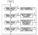
- the circuit diagram of the power supply device which concerns on 1st Embodiment is shown. It is a flowchart which shows the operation of a control part.
- the power supply device 1 shown in FIG. 1 stores the electric power generated by sunlight in the storage battery 2, and when the load device 3 is connected, supplies the electric power from the storage battery 2 to the load device 3.
- the power supply device 1 includes a solar cell panel 4, a storage battery 2 charged by the generated power of the solar cell panel 4, a charging switch 5 for turning on / off charging from the solar cell panel 4 to the storage battery 2, and a load device 3 from the storage battery 2. It has a discharge switch 6 for turning on / off the discharge to, a charge current detector 7, a discharge current detector 8, and a control circuit 9 for controlling charging / discharging of the storage battery 2.
- the load device 3 is, for example, a street light, and is a device that can be operated by the electric power of the storage battery 2.
- the solar cell panel 4 is made of a semiconductor such as silicon, and generates a direct current when sunlight is incident on it.
- the positive electrode of the solar cell panel 4 is connected to the high potential line L1, and the negative electrode is connected to the low potential line L2.
- the storage battery 2 is configured by connecting a plurality of secondary battery cells such as nickel-metal hydride batteries in series, and stores the generated power of the solar cell panel 4.
- the load device 3 When the load device 3 is connected to the output terminals 10 and 11 and the discharge switch 6 is turned on, the storage battery 2 discharges toward the load device 3.
- the number of secondary battery cells connected in series is determined according to the input voltage required by the load device 3.
- the diode 12 is inserted into the high potential line L1 in order to prevent the backflow of current to the solar cell panel 4. Specifically, the anode of the diode 12 is connected to the positive electrode of the solar cell panel 4, and the cathode is connected to the positive electrode side of the storage battery 2.
- the charging switch 5 is made of, for example, a P-channel MOSFET.
- the source of the MOSFET 5 is connected to the positive electrode side of the solar cell panel 4, the drain is connected to the positive electrode side of the storage battery 2, and the gate is connected to the control circuit 9. Further, the MOSFET 5 is inserted into the high potential line L1 so that the anode of the parasitic diode is connected to the positive electrode side of the storage battery 2 and the cathode is connected to the cathode of the diode 12.
- the charging switch 5 switches on and off by a signal from the control circuit 9 to the gate of the MOSFET. When the charging switch 5 is turned on, the current from the solar cell panel 4 is directed toward the storage battery 2 to charge the storage battery 2.
- the discharge switch 6 is connected between the positive electrode of the storage battery 2 and the output terminal 10 on the high potential side, and is turned on and off by a signal from the control circuit 9. When the discharge switch 6 is turned on, discharge is started from the storage battery 2 toward the load device 3.
- the discharge switch 6 is an example of a switch element.
- the charging current detector 7 is composed of a resistor connected in series with the low potential line L2, and detects the charging current IB flowing through the storage battery 2.
- the discharge current detector 8 includes a resistor connected between the positive electrode of the storage battery 2 and the output terminal 10, and detects the discharge current IC flowing from the storage battery 2.
- the thermistor 14 detects the battery temperature T of the storage battery 2.
- the control circuit 9 is composed of a microcomputer, and is supplied with operating power for operating the control circuit 9 via a power supply IC 13 connected between the high potential line L1 and the low potential line L2. Normally, the power generated from the solar cell panel 4 is supplied to the control circuit 9 as operating power.
- the battery voltage VB of the storage battery, the charging current IB detected by the charging current detector, and the battery temperature T detected by the thermistor 14 are input to the control circuit 9.
- the control circuit 9 determines the state of the storage battery 2 based on the input battery voltage VB, charging current IB, and battery temperature T of the storage battery 2, and controls the on / off of the charging switch 5. When the load device 3 is connected, the control circuit 9 further controls the on / off of the discharge switch 6 based on the battery voltage VB, the discharge current IC, and the battery temperature T.
- the control circuit 9 is an example of a control unit.
- the solar cell panel 4 generates electric power by the incident of sunlight in the daytime and outputs electric power.
- the generated power from the solar cell panel 4 is supplied to the control circuit 9 via the power supply IC 13.
- the control circuit 9 starts the control.
- the control circuit 9 determines that the storage battery 2 needs to be charged based on the battery voltage VB (step S1: YES)
- the control circuit 9 turns on the charging switch 5 and starts charging the storage battery 2 (step S2).
- the operating power is an example of a predetermined power.
- control circuit 9 integrates the amount of charge to the storage battery 2, and when it is determined that the storage battery 2 is fully charged (step S3: YES), the charging switch 5 is turned off and the storage battery is charged. The charging of the storage battery 2 is stopped to prevent the storage battery 2 from being overcharged (step S4). At this time, the control circuit 9 continues to operate with the generated power of the solar cell panel 4.
- control circuit 9 continues stable operation due to the generated power of the solar cell panel 4.
- step S5 when the illuminance decreases due to bad weather or sunset and the generated power of the solar cell panel 4 becomes less than the operating power (step S5: YES), the voltage on the input side of the power supply IC 13 is equal to or less than the battery voltage VB of the storage battery 2.
- the shortage of operating power is supplied to the control circuit 9 via the parasitic diode by discharging from the storage battery 2.
- the control circuit 9 can continue to operate.
- the control circuit 9 keeps the charging switch 5 off to prevent overcharging (step S6).
- step S7 When it is determined that the storage battery 2 needs to be charged due to the discharge from the storage battery 2 to the control circuit 9 when the generated power is lower than the operating power (step S7: YES), the control circuit 9 operates. Since the shortage of electric power is supplied from the storage battery 2 via the parasitic diode, the control circuit 9 can continue to operate. Therefore, the control circuit 9 switches the charging switch 5 on and starts charging the storage battery 2 (step S8).
- the directions of the charging current of the storage battery 2 and the discharge current from the storage battery 2 for compensating for the shortage of the operating power of the control circuit 9 are opposite to each other. Therefore, when the discharge current to the control circuit 9 is larger than the charge current to the storage battery 2, the charge current detector 7 detects the reverse current. Since the detection of the reverse current indicates that the storage battery 2 is not substantially charged, the control circuit 9 switches the charging switch 5 off to stop the apparent charging of the storage battery 2. At this time, even if the charging switch 5 is turned off, power is supplied from the storage battery 2 to the control circuit 9 via the parasitic diode, so that the control circuit 9 can continue to operate.
- the control circuit 9 turns on the discharge switch 6 to discharge the battery 2 toward the street light. Then, when the battery voltage VB becomes equal to or lower than a predetermined value, the control circuit 9 switches the discharge switch 6 off to stop the discharge of the storage battery 2 and prevent the storage battery 2 from being over-discharged.
- the operation of the control circuit 9 can be continued at night.
- steps S5 to S8 even if the generated power is insufficient for the operation of the control circuit 9, the insufficient power is supplied from the storage battery 2, so that the control circuit 9 can continue stable operation. ..
- the insufficient power is transferred from the storage battery 2 to the control circuit 9 via the parasitic diode of the FET constituting the charging switch 5. Since it is supplied to, the operation of the control circuit 9 can be continued. Therefore, since it is not necessary to provide a separate power supply for continuing the operation of the control circuit, the configuration of the power supply device 1 can be simplified and the number of component parts can be reduced.
- the configuration of the power supply device 1 can be simplified and the number of components can be reduced. ..
- the P-channel MOSFET is used as the charging switch 5 in the above embodiment, an N-channel MOSFET may be used. Even in this case, when the generated power is insufficient for the operating power of the control circuit 9, the anode of the parasitic diode of the N-channel type MOSFET is the storage battery 2 in order to allow current to flow from the storage battery 2 to the control circuit 9.
- the MOSFET may be connected to the high potential line L1 so that the positive electrode side and the cathode are connected to the control circuit side.
Landscapes
- Engineering & Computer Science (AREA)
- Power Engineering (AREA)
- Charge And Discharge Circuits For Batteries Or The Like (AREA)
- Secondary Cells (AREA)
Abstract
天候や時間帯に左右されずに安定して動作する太陽電池パネルを含む電源装置を提供する。電源装置1は、太陽光で発電する太陽電池パネル4と、太陽電池パネルの発電電力を蓄電するとともに負荷装置に放電可能な蓄電池2と、太陽電池パネル4から蓄電池2への充電と、蓄電池2から負荷装置3への放電とを制御する制御回路9と、を備える。制御回路9は、太陽電池パネル4による発電電力が所定電力以上のときは太陽電池パネル4からの給電により、発電電力が所定電力未満となるときは、蓄電池2からの給電により動作する。
Description
本発明は、電源装置に関する。
太陽電池パネルで発電した電力により動作する装置が知られている。しかし、太陽電池パネルは、日射の確保できない夜間や曇天時には発電を行うことができないため装置を動作させることができない。そこで、発電した電力を蓄電するための蓄電池を備えた装置が提案されている(特許文献1)。
上記装置は、蓄電池への充電及び蓄電池からの放電を制御するために、制御回路を備えている。制御回路は、昼間は太陽電池パネルからの出力により、夜間は蓄電池からの出力により動作するようになっている。しかし、太陽電池パネルからの出力は天候に左右されて不安定であるため、制御回路を安定して動作させるためにさらに別の電源が必要となっていた。
本発明は、上記問題点に鑑みて、その目的は、太陽電池パネルが発電し、制御回路が天候に左右されずに安定して動作する電源装置を提供することにある。
<本発明の第1の態様>
本発明の第1の態様の電源装置は、太陽光で発電する太陽電池パネルと、前記太陽電池パネルで発電された電力を蓄電するとともに負荷装置に放電可能な蓄電池と、所定電力で動作し、前記太陽電池パネルから前記蓄電池への充電と、前記蓄電池から前記負荷装置への放電とを制御する制御部と、を備え、前記制御部は、前記太陽電池パネルによる発電電力が前記所定電力以上のときは前記太陽電池パネルから給電されて動作し、前記発電電力が前記所定電力未満となるときは、前記発電電力に加えて前記蓄電池から給電されて動作する。
本発明の第1の態様の電源装置は、太陽光で発電する太陽電池パネルと、前記太陽電池パネルで発電された電力を蓄電するとともに負荷装置に放電可能な蓄電池と、所定電力で動作し、前記太陽電池パネルから前記蓄電池への充電と、前記蓄電池から前記負荷装置への放電とを制御する制御部と、を備え、前記制御部は、前記太陽電池パネルによる発電電力が前記所定電力以上のときは前記太陽電池パネルから給電されて動作し、前記発電電力が前記所定電力未満となるときは、前記発電電力に加えて前記蓄電池から給電されて動作する。
上記構成により、太陽電池パネルによる発電電力が所定電力より低下したときは、所定電力に対する発電電力の不足分は、蓄電池から制御部への放電によって補われるので、制御部は安定してその動作を継続できる。
<本発明の第2の態様>
本発明の第2の態様の電源装置は、上記第1の態様において、前記太陽電池パネルから前記蓄電池への充電をオンオフする電解効果トランジスタ(FET)をさらに有し、前記FETは、寄生ダイオードのアノードが前記蓄電池の正極に接続されると共にカソードが前記太陽電池パネルの正極に接続されるように、前記太陽電池パネルと前記蓄電池との間に接続される。
本発明の第2の態様の電源装置は、上記第1の態様において、前記太陽電池パネルから前記蓄電池への充電をオンオフする電解効果トランジスタ(FET)をさらに有し、前記FETは、寄生ダイオードのアノードが前記蓄電池の正極に接続されると共にカソードが前記太陽電池パネルの正極に接続されるように、前記太陽電池パネルと前記蓄電池との間に接続される。
上記構成により、発電電力が制御部の動作電力未満となるとき、動作電力の不足分は、寄生ダイオードを介して蓄電池から制御部へ供給される。従って、制御部は動作を継続できる。寄生ダイオードは、太陽電池パネルから蓄電池への充電をオンオフするFETに含まれているので、蓄電池から制御部に給電するために別の部品を設けずに済むので、電源装置の構成を簡単にできる。
<本発明の第3の態様>
本発明の第3の態様の電源装置は、上記第1又は第2の態様において、前記蓄電池から前記負荷装置への放電をオンオフするスイッチ素子をさらに有し、前記制御部は、前記スイッチ素子のオンオフを制御する。上記構成により、充電制御と放電制御とを単一の制御部で行うことができるので、電源装置の構成を簡単にして部品総数を削減できる。
本発明の第3の態様の電源装置は、上記第1又は第2の態様において、前記蓄電池から前記負荷装置への放電をオンオフするスイッチ素子をさらに有し、前記制御部は、前記スイッチ素子のオンオフを制御する。上記構成により、充電制御と放電制御とを単一の制御部で行うことができるので、電源装置の構成を簡単にして部品総数を削減できる。
本開示によれば、蓄電池の充放電を制御する制御部が時間帯や天候に左右されずに安定して動作する電源装置を提供することができる。
本発明の実施形態を、図面を参照して説明する。
図1に示す電源装置1は、太陽光によって発電された電力を蓄電池2に蓄電し、負荷装置3が接続されると負荷装置3に対し蓄電池2からの電力を給電する。電源装置1は、太陽電池パネル4と、太陽電池パネル4の発電電力で充電される蓄電池2と、太陽電池パネル4から蓄電池2への充電をオンオフする充電スイッチ5と、蓄電池2から負荷装置3への放電をオンオフする放電スイッチ6と、充電電流検出器7と、放電電流検出器8と、蓄電池2の充放電を制御する制御回路9とを有する。負荷装置3は、例えば街灯であり、蓄電池2の電力により動作可能な装置である。
太陽電池パネル4は、例えばシリコンなどの半導体で作製され、太陽光が入射すると直流電流を生成する。太陽電池パネル4の正極は、高電位ラインL1に接続され、負極は低電位ラインL2に接続される。
蓄電池2は、ニッケル水素電池などの二次電池セルの複数個を直列に接続して構成され、太陽電池パネル4の発電電力を蓄電する。蓄電池2は、出力端子10、11に負荷装置3が接続され放電スイッチ6がオンになると、負荷装置3に向けて放電する。直列に接続される二次電池セルの個数は、負荷装置3が必要とする入力電圧に応じて決められる。
ダイオード12が、太陽電池パネル4への電流の逆流を防止するために、高電位ラインL1に挿入される。具体的には、ダイオード12のアノードが太陽電池パネル4の正極に接続され、カソードが蓄電池2の正極側に接続される。
充電スイッチ5は、例えばPチャネル型MOSFETからなる。MOSFET5のソースが太陽電池パネル4の正極側に接続され、ドレインが蓄電池2の正極側に接続され、ゲートが制御回路9に接続される。さらに、MOSFET5は、寄生ダイオードのアノードが蓄電池2の正極側に、カソードがダイオード12のカソードに接続されるように高電位ラインL1に挿入される。充電スイッチ5は、制御回路9からMOSFETのゲートへの信号によりオンオフを切替える。充電スイッチ5は、オンになると太陽電池パネル4からの電流を蓄電池2に向けて流し蓄電池2を充電する。
放電スイッチ6は、蓄電池2の正極と高電位側の出力端子10との間に接続され、制御回路9からの信号によりオンオフされる。放電スイッチ6がオンになると、蓄電池2から負荷装置3に向けて放電が開始される。なお、放電スイッチ6はスイッチ素子の一例である。
充電電流検出器7は、低電位ラインL2に直列に接続された抵抗器からなり、蓄電池2を流れる充電電流IBを検出する。放電電流検出器8は、蓄電池2の正極と出力端子10との間に接続された抵抗器からなり、蓄電池2から流れる放電電流ICを検出する。
サーミスタ14は、蓄電池2の電池温度Tを検出する。
制御回路9は、マイコンからなり、高電位ラインL1と低電位ラインL2との間に接続された電源IC13を介して、制御回路9を動作させる動作電力が供給される。通常は、太陽電池パネル4からの発電電力が動作電力として制御回路9に供給される。制御回路9には、蓄電池の電池電圧VB、充電電流検出器で検出された充電電流IB、サーミスタ14にて検出された電池温度Tが入力される。制御回路9は、入力された蓄電池2の電池電圧VB、充電電流IB、及び電池温度Tに基づいて、蓄電池2の状態を判断し、充電スイッチ5のオンオフを制御する。制御回路9は、負荷装置3が接続された場合は、さらに、電池電圧VB、放電電流IC、電池温度Tに基づき、放電スイッチ6のオンオフを制御する。なお、制御回路9は制御部の一例である。
制御回路9は、マイコンからなり、高電位ラインL1と低電位ラインL2との間に接続された電源IC13を介して、制御回路9を動作させる動作電力が供給される。通常は、太陽電池パネル4からの発電電力が動作電力として制御回路9に供給される。制御回路9には、蓄電池の電池電圧VB、充電電流検出器で検出された充電電流IB、サーミスタ14にて検出された電池温度Tが入力される。制御回路9は、入力された蓄電池2の電池電圧VB、充電電流IB、及び電池温度Tに基づいて、蓄電池2の状態を判断し、充電スイッチ5のオンオフを制御する。制御回路9は、負荷装置3が接続された場合は、さらに、電池電圧VB、放電電流IC、電池温度Tに基づき、放電スイッチ6のオンオフを制御する。なお、制御回路9は制御部の一例である。
次に、電源装置1の動作について図2を参照して説明する。
太陽電池パネル4は、昼間は、太陽光の入射により発電して電力を出力する。太陽電池パネル4からの発電電力は、電源IC13を介して制御回路9に供給される。制御回路9への供給電力が、制御回路9の動作に必要な電力(以下、動作電力と称す)を満たしていると、制御回路9は制御を開始する。次に、制御回路9は、電池電圧VBに基づき蓄電池2の充電が必要と判断すると(ステップS1:YES)、充電スイッチ5をオンにして蓄電池2の充電を開始する(ステップS2)。なお、動作電力は、所定電力の一例である。
蓄電池2を充電しているとき、制御回路9は、蓄電池2への充電量を積算し、蓄電池2の満充電を判断した場合には(ステップS3:YES)、充電スイッチ5をオフにして蓄電池2の充電を停止し、蓄電池2の過充電を防止する(ステップS4)。このとき、制御回路9は、太陽電池パネル4の発電電力により動作を継続する。
このように、ステップS1~S4では、制御回路9は、太陽電池パネル4の発電電力により安定した動作を継続する。
一方、天候不良や日没により照度が低下して太陽電池パネル4の発電電力が動作電力未満になると(ステップS5:YES)、電源IC13の入力側の電圧が蓄電池2の電池電圧VB以下であれば、動作電力の不足分が蓄電池2からの放電により寄生ダイオードを介して制御回路9に供給される。これにより、制御回路9は動作を継続することができる。
このとき、蓄電池2が満充電であれば、制御回路9は、充電スイッチ5をオフに維持して過充電を防止する(ステップS6)。
このとき、蓄電池2が満充電であれば、制御回路9は、充電スイッチ5をオフに維持して過充電を防止する(ステップS6)。
発電電力が動作電力を下回っているときに、蓄電池2から制御回路9への放電により蓄電池2への充電が必要になったと判断される場合(ステップS7:YES)、制御回路9には、動作電力の不足分が蓄電池2より寄生ダイオードを介して供給されているので、制御回路9は動作を継続できる。従って、制御回路9は、充電スイッチ5をオンに切替えて蓄電池2の充電を開始する(ステップS8)。
このとき、蓄電池2の充電電流と、制御回路9の動作電力の不足分を補うための蓄電池2からの放電電流との向きは、互いに逆方向になる。従って、制御回路9への放電電流が蓄電池2への充電電流よりも多くなる場合、充電電流検出器7は、逆電流を検出する。逆電流の検出は、蓄電池2への実質的な充電が行われていないことを示すため、制御回路9は、充電スイッチ5をオフに切替えて蓄電池2の見かけ上の充電を停止させる。このとき、充電スイッチ5がオフになっても寄生ダイオードを介して蓄電池2から制御回路9に対して給電が行われているので、制御回路9は動作を継続できる。
次に、夜間のため太陽電池パネル4が発電できない場合、制御回路9には、蓄電池2から放電された電力が寄生ダイオードを介して供給されるので、制御回路9は動作を継続する。このとき、負荷装置3として街灯が接続された場合、制御回路9は、放電スイッチ6をオンにして、蓄電池2から街灯に向けて放電させる。そして、制御回路9は、電池電圧VBが所定値以下になったときに放電スイッチ6をオフに切替えて蓄電池2の放電を停止し、蓄電池2の過放電を防止する。
制御回路9の動作電力は、負荷装置3の消費電力に比較すると少量であるため、夜間、制御回路9の動作を継続させることができる。
このように、ステップS5~S8では、発電電力が制御回路9の動作に不十分であっても、不足分の電力が蓄電池2より給電されるので、制御回路9は、安定した動作を継続できる。
上記実施の形態では、太陽電池パネル4での発電電力が制御回路9の動作電力を下回る場合、不足分の電力を、充電スイッチ5を構成するFETの寄生ダイオードを介して蓄電池2から制御回路9へ供給しているので、制御回路9の動作を継続させることができる。
よって、制御回路の動作継続のために別に電源を設けずに済むので、電源装置1の構成を簡単にして、構成部品の数を減らすことができる。
よって、制御回路の動作継続のために別に電源を設けずに済むので、電源装置1の構成を簡単にして、構成部品の数を減らすことができる。
さらに、蓄電池2の充電と蓄電池2からの放電との制御を、単一の制御回路9を用いて行っているので、電源装置1の構成を簡単にして、構成部品の数を減らすことができる。
なお、上記実施の形態において、充電スイッチ5としてPチャネル型MOSFETを用いたが、Nチャネル型MOSFETを用いても良い。この場合であっても、発電電力が制御回路9の動作電力に不足する場合に、蓄電池2から制御回路9に向けて電流を流すために、Nチャネル型MOSFETの寄生ダイオードのアノードが蓄電池2の正極側、カソードが制御回路側に接続されるように、MOSFETを高電位ラインL1に接続すれば良い。
1 電源装置
2 蓄電池
3 負荷装置
4 太陽電池パネル
5 充電スイッチ
9 制御回路
2 蓄電池
3 負荷装置
4 太陽電池パネル
5 充電スイッチ
9 制御回路
Claims (3)
- 太陽光で発電する太陽電池パネルと、
前記太陽電池パネルで発電された電力を蓄電するとともに負荷装置に放電可能な蓄電池と、
所定電力で動作し、前記太陽電池パネルから前記蓄電池への充電と、前記蓄電池から前記負荷装置への放電とを制御する制御部と、を備え、
前記制御部は、前記太陽電池パネルによる発電電力が前記所定電力以上のときは前記太陽電池パネルから給電されて動作し、
前記発電電力が前記所定電力未満となるときは、前記発電電力に加えて前記蓄電池から給電されて動作する、電源装置。 - 前記太陽電池パネルから前記蓄電池への充電をオンオフする電解効果トランジスタ(FET)をさらに有し、
前記FETは、寄生ダイオードのアノードが前記蓄電池の正極に接続されると共にカソードが前記太陽電池パネルの正極に接続されるように、前記太陽電池パネルと前記蓄電池との間に接続される、請求項1記載の電源装置。 - 前記蓄電池から前記負荷装置への放電をオンオフするスイッチ素子をさらに有し、
前記制御部は、前記スイッチ素子のオンオフを制御する、請求項1または2に記載の電源装置。
Applications Claiming Priority (2)
| Application Number | Priority Date | Filing Date | Title |
|---|---|---|---|
| JP2020046723A JP2021151022A (ja) | 2020-03-17 | 2020-03-17 | 電源装置 |
| JP2020-046723 | 2020-03-17 |
Publications (1)
| Publication Number | Publication Date |
|---|---|
| WO2021186904A1 true WO2021186904A1 (ja) | 2021-09-23 |
Family
ID=77771169
Family Applications (1)
| Application Number | Title | Priority Date | Filing Date |
|---|---|---|---|
| PCT/JP2021/002795 Ceased WO2021186904A1 (ja) | 2020-03-17 | 2021-01-27 | 電源装置 |
Country Status (2)
| Country | Link |
|---|---|
| JP (1) | JP2021151022A (ja) |
| WO (1) | WO2021186904A1 (ja) |
Citations (3)
| Publication number | Priority date | Publication date | Assignee | Title |
|---|---|---|---|---|
| JP2003330087A (ja) * | 2002-05-10 | 2003-11-19 | Canon Inc | 太陽電池を備えた交換レンズ |
| JP2008131710A (ja) * | 2006-11-20 | 2008-06-05 | Nippon Telegr & Teleph Corp <Ntt> | 電源システム、電源システムの制御方法、電源システムの制御方法を実行するためのプログラムおよび電源システムの制御方法を実行するためのプログラムを記録した記録媒体 |
| JP2008141806A (ja) * | 2006-11-30 | 2008-06-19 | Kuroi Electric Co Ltd | 太陽電池による蓄電池充電回路 |
-
2020
- 2020-03-17 JP JP2020046723A patent/JP2021151022A/ja active Pending
-
2021
- 2021-01-27 WO PCT/JP2021/002795 patent/WO2021186904A1/ja not_active Ceased
Patent Citations (3)
| Publication number | Priority date | Publication date | Assignee | Title |
|---|---|---|---|---|
| JP2003330087A (ja) * | 2002-05-10 | 2003-11-19 | Canon Inc | 太陽電池を備えた交換レンズ |
| JP2008131710A (ja) * | 2006-11-20 | 2008-06-05 | Nippon Telegr & Teleph Corp <Ntt> | 電源システム、電源システムの制御方法、電源システムの制御方法を実行するためのプログラムおよび電源システムの制御方法を実行するためのプログラムを記録した記録媒体 |
| JP2008141806A (ja) * | 2006-11-30 | 2008-06-19 | Kuroi Electric Co Ltd | 太陽電池による蓄電池充電回路 |
Also Published As
| Publication number | Publication date |
|---|---|
| JP2021151022A (ja) | 2021-09-27 |
Similar Documents
| Publication | Publication Date | Title |
|---|---|---|
| CN100384050C (zh) | 电源装置以及该电源装置中所使用的控制方法 | |
| KR101852638B1 (ko) | 충방전 제어 회로 및 배터리 장치 | |
| US9893527B2 (en) | Power storage system and power storage method | |
| EP2317597B1 (en) | Battery pack | |
| US7463008B2 (en) | Power supply apparatus with transistor control for constant current between series-connected battery blocks | |
| JP6950746B2 (ja) | 電源システム | |
| KR101516193B1 (ko) | 태양광 충전 제어 장치 및 그 제어 방법 | |
| US20080169784A1 (en) | Solar power system | |
| US20110285354A1 (en) | Rechargeable battery controlling circuit, rechargeable battery controlling device, independent power system and battery pack | |
| JP2012029513A (ja) | 太陽光発電による充放電制御装置及び太陽光発電による充放電制御方法 | |
| JP2011250608A (ja) | 太陽電池システム | |
| WO2012050195A1 (ja) | 電力供給システム | |
| WO2012050180A1 (ja) | 優先回路及び電力供給システム | |
| JP6713101B2 (ja) | 蓄電池システム及び蓄電池の制御方法 | |
| KR102042392B1 (ko) | 에너지 저장 시스템 및 이를 포함하는 전자 시스템 | |
| JP3485445B2 (ja) | 太陽電池式電源装置 | |
| JP7052326B2 (ja) | 電源装置及び通信装置 | |
| JP4977805B1 (ja) | 独立型電源装置 | |
| JP2004064855A (ja) | 光電池を使用した電源装置 | |
| WO2021186904A1 (ja) | 電源装置 | |
| WO2012133186A1 (ja) | スイッチ回路制御部及び充放電システム | |
| KR101885187B1 (ko) | 오프-그리드(Off-Grid) 전력공급장치용 배터리 시스템 | |
| KR101022168B1 (ko) | 태양전지모듈용 전원관리장치의 제어방법 | |
| JP2005210776A (ja) | バッテリーチャージャー付ポータブル電源システム | |
| JP6923121B2 (ja) | 電力供給装置 |
Legal Events
| Date | Code | Title | Description |
|---|---|---|---|
| 121 | Ep: the epo has been informed by wipo that ep was designated in this application |
Ref document number: 21771902 Country of ref document: EP Kind code of ref document: A1 |
|
| NENP | Non-entry into the national phase |
Ref country code: DE |
|
| 122 | Ep: pct application non-entry in european phase |
Ref document number: 21771902 Country of ref document: EP Kind code of ref document: A1 |