WO2021186823A1 - 血管モデル - Google Patents
血管モデル Download PDFInfo
- Publication number
- WO2021186823A1 WO2021186823A1 PCT/JP2020/047406 JP2020047406W WO2021186823A1 WO 2021186823 A1 WO2021186823 A1 WO 2021186823A1 JP 2020047406 W JP2020047406 W JP 2020047406W WO 2021186823 A1 WO2021186823 A1 WO 2021186823A1
- Authority
- WO
- WIPO (PCT)
- Prior art keywords
- blood vessel
- porous body
- vessel model
- diffusion
- model
- Prior art date
- Legal status (The legal status is an assumption and is not a legal conclusion. Google has not performed a legal analysis and makes no representation as to the accuracy of the status listed.)
- Ceased
Links
Images



Classifications
-
- G—PHYSICS
- G09—EDUCATION; CRYPTOGRAPHY; DISPLAY; ADVERTISING; SEALS
- G09B—EDUCATIONAL OR DEMONSTRATION APPLIANCES; APPLIANCES FOR TEACHING, OR COMMUNICATING WITH, THE BLIND, DEAF OR MUTE; MODELS; PLANETARIA; GLOBES; MAPS; DIAGRAMS
- G09B23/00—Models for scientific, medical, or mathematical purposes, e.g. full-sized devices for demonstration purposes
- G09B23/28—Models for scientific, medical, or mathematical purposes, e.g. full-sized devices for demonstration purposes for medicine
- G09B23/30—Anatomical models
-
- G—PHYSICS
- G09—EDUCATION; CRYPTOGRAPHY; DISPLAY; ADVERTISING; SEALS
- G09B—EDUCATIONAL OR DEMONSTRATION APPLIANCES; APPLIANCES FOR TEACHING, OR COMMUNICATING WITH, THE BLIND, DEAF OR MUTE; MODELS; PLANETARIA; GLOBES; MAPS; DIAGRAMS
- G09B9/00—Simulators for teaching or training purposes
Definitions
- the techniques disclosed herein relate to vascular models.
- a simulator equipped with a blood vessel model (simulated blood vessel, etc.) that imitates an actual blood vessel is used to simulate clinical treatment or examination using a catheter or the like.
- a material for forming a simulated blood vessel or the like provided in such a simulator or the like for example, a point of providing a porous body is disclosed (see, for example, Patent Document 1).
- angiography may be used to grasp the hemodynamics such as blood flow velocity and blood viscosity, and the state of obstruction of blood vessels.
- a contrast medium having low X-ray transmittance is injected from a catheter inserted into a blood vessel to perform X-ray imaging.
- the surgeon visually observes the hemodynamics and vascular condition by observing the flow of the contrast medium from the change in contrast in the obtained fluoroscopic X-ray image (still image or moving image, also called "cine image”). You can check at.
- the concentration of the contrast medium is set to a concentration that is not captured in the X-ray fluoroscopic image in the portion where the contrast medium is imaged only in the X-ray fluoroscopic image using the blood vessel model.
- a blood vessel model (simulated human body) that simulates a diffused image of a clinical contrast medium by diluting the contrast medium until it becomes available is disclosed (see, for example, Patent Document 2).
- This specification discloses a technique capable of solving the above-mentioned problems.
- the blood vessel model disclosed in the present specification is a blood vessel model, which is connected to a flow path forming portion forming a fluid flow path extending in the long axis direction of the blood vessel model and the flow path forming portion.
- the diffusion portion is provided with a diffusion portion formed of a porous body having pores, and the diffusion portion has an inner portion and an outer portion located outside the inner portion, and in the major axis direction, the diffusion portion has.
- the flow resistance in the outer portion is higher than the flow resistance in the inner portion.
- the flow path forming portion includes a diffusion portion formed of a porous body having pores.
- the fluid (for example, a contrast medium) flowing through the fluid flow path can be discharged to the outside while being diffused from the pores of the porous body.
- the diffusion portion formed by the porous body functions as a diffusion flow path (buffer flow path) that disperses the pressure and flow velocity of the contrast medium that has flowed into the fluid flow path.
- the contrast medium that has flowed into the diffusing portion is discharged to the outside from the portion having low flow resistance in the diffusing portion.
- the diffusion portion has an inner portion and an outer portion having a flow resistance higher than the flow resistance of the inner portion.
- the contrast medium that has flowed into the diffusing portion is first filled in the inner portion of the diffusing portion having a low flow resistance, then enters the outer portion having a higher flow resistance, and is discharged to the outside of the diffusing portion. .. Therefore, the contrast medium is diffused and discharged to the outside substantially uniformly from the entire outer surface of the outer portion of the diffusion portion. Further, since the flow resistance of the outer portion of the diffusing portion is high, the contrast medium is more finely diffused when it is discharged to the outside. Therefore, in this blood vessel model, in the X-ray fluoroscopic image obtained when the contrast medium is used, the appearance of the contrast medium's shading confirmed in the actual clinical X-ray fluoroscopic image (specifically, the contrast medium is an arteriole).
- the diffusion portion includes, as the porous body, a first porous body constituting the outer portion and a second porous body constituting the inner portion. May be.
- the diffusion portion may have a separate configuration composed of an outer portion and an inner portion. According to this blood vessel model, the diffusion portion can be easily produced, and the combination of the outer portion and the inner portion can be easily changed.
- the diffusion portion may be a bottomed cylindrical body having one end that opens into the fluid flow path in the flow path forming portion. According to this blood vessel model, since the diffusion portion is a bottomed cylindrical body having one end that opens into the fluid flow path and the other end that is externally closed, even at the end of the diffusion portion. It is possible to simulate the shading of the contrast medium in the X-ray fluoroscopic image obtained when the contrast medium is used in an actual clinical setting.
- the pore diameter of the porous body in the outer portion may be smaller than the pore diameter of the porous body in the inner portion.
- the smaller the pore size of the porous body the higher the flow resistance in the porous body. Therefore, in this blood vessel model, the flow resistance of the porous body in the outer portion is higher than the flow resistance of the porous body in the inner portion. Therefore, according to this blood vessel model, by adjusting the pore size of the porous body in the outer part and the pore size of the porous body in the inner part, in an X-ray fluoroscopic image obtained when a contrast medium is used, in actual clinical practice.
- At least one pore of the porous body in the outer portion and the porous body in the inner portion may be filled with an elastic body in the diffusion portion.
- the pores of the porous body in the diffusion part, are filled with an elastic body, so that the pressure in the fluid flow path is increased. While it is low, each pore of the porous body can be sealed, and when the pressure in the fluid flow path increases due to the inflow of the contrast medium, each pore of the porous body can be opened.
- the contrast medium can be diffused and discharged more finely, and the state of shading of the contrast medium (diffusion and disappearance image of the contrast medium) in the X-ray fluoroscopic image obtained when the contrast medium is used in an actual clinical setting can be actually observed. It can be closer to the contrast-enhanced image observed clinically.
- the contrast medium that has entered the diffusing part is more reliably discharged to the outside of the diffusing part due to the elasticity of the elastic body, so that the contrast medium is suppressed from remaining in the diffusing part, and eventually the diffusing part is regenerated. Make it available.
- the blood vessel model when used in a wet state immersed in a fluid (water, physiological saline, etc.), the fluid that fills the periphery of the blood vessel model flows back from each pore of the porous body into the fluid flow path. Can be suppressed.
- a fluid water, physiological saline, etc.
- both the pores of the porous body in the outer portion and the porous body in the inner portion are filled with an elastic body, and the porous body in the outer portion is filled.
- the elastic modulus of the elastic body filled in the pores of the body may be higher than the elastic modulus of the elastic body filled in the pores of the porous body in the inner portion.
- the higher the elastic modulus of the elastic body the higher the flow resistance in the porous body filled with the elastic body. Therefore, according to this blood vessel model, when the flow resistances of the porous body constituting the outer portion and the porous body constituting the inner portion are substantially equal to each other, the flow resistance in the outer portion is the inner portion. Higher than the flow resistance in.
- this blood vessel model by adjusting the elastic coefficient of the elastic body in the outer portion and the elastic coefficient of the elastic body in the inner portion, in an X-ray fluoroscopic image obtained when a contrast medium is used, in actual clinical practice. It is possible to simulate the state of shading of the contrast medium confirmed by the X-ray fluoroscopic image (specifically, the state in which the contrast medium spreads along the arterioles and then diffuses into the venules and disappears). Therefore, it is possible to provide a blood vessel model in which the X-ray fluoroscopic image obtained when the contrast medium is used in an actual clinical setting is approximated to the contrast image observed in the actual clinical practice.
- the flow path forming portion may be a tubular body extending in the long axis direction of the blood vessel model, and the diffusion portion may be provided at the tip end portion of the tubular body.
- the diffusion portion since the diffusion portion is provided at the tip of the flow path forming portion (tubular body), it can be obtained on the tip end side of the flow path forming portion when a contrast medium is used in an actual clinical setting. It is possible to simulate the shading of the contrast medium in the X-ray fluoroscopic image.
- the flow path forming portion is a tubular body extending in the long axis direction of the blood vessel model, and the diffusion portion may be provided at a branching portion where the tubular body branches. good.
- the diffusion portion is provided at the bifurcation portion where the flow path forming portion (tubular body) branches, an X-ray fluoroscopic image obtained at the bifurcation portion when a contrast medium is used in an actual clinical site. It is possible to simulate the state of shading of the contrast medium in.
- the flow path forming portion may be formed of a porous body. According to this blood vessel model, by forming the flow path forming portion with the porous body, it can function as a diffusing portion that diffuses the fluid flowing through the fluid flow path from the pores of the porous body and discharges it to the outside. ..
- the in-tube pressure in the diffusion portion may be lower than the in-tube pressure in the flow path forming portion.
- the contrast medium supplied to the blood vessel model is reduced from being discharged to the outside at the flow path forming portion, the contrast medium is distributed to the diffusion portion, and the contrast medium is constant at the diffusion portion. It can be diffused to a concentration (flow rate) and discharged. Therefore, it is possible to provide a blood vessel model in which the X-ray fluoroscopic image obtained when the contrast medium is used in an actual clinical setting is approximated to the contrast image blood vessel observed in the actual clinical practice.
- the blood vessel model at least a part of the outer peripheral surface of the blood vessel model may be coated with an elastic material. According to this blood vessel model, the elastic modulus of the blood vessel model can be adjusted by coating.
- the technique disclosed in the present specification can be realized in various forms, for example, a simulator provided with a blood vessel model, a method for manufacturing the same, and the like.
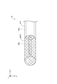
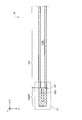
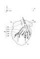
- FIG. 1 is an explanatory diagram schematically showing the configuration of the heart simulator 1 in the first embodiment
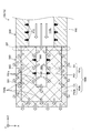
- FIG. 2 schematically shows the configuration of a part of the cardiovascular model 10 (X1 part in FIG. 1) in the first embodiment. It is explanatory drawing which shows.
- FIG. 3 is an enlarged explanatory view showing a cross-sectional configuration of a part (X2 part of FIG. 1) of the cardiovascular model 10 in the first embodiment
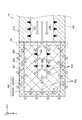
- FIG. 4 is a part of the cardiovascular model 10 in the first embodiment. It is explanatory drawing which enlarges and shows the cross-sectional structure of (X1 part of FIG. 1, FIG. 2).
- the heart simulator 1 is a simulator that reproduces the heart and the blood vessels that go around the surface of the heart, and includes a cardiovascular model 10 and a heart model 20. More specifically, the heart simulator 1 is composed of a heart model 20 and a cardiovascular model 10 arranged on the surface S1 of the heart model 20. According to such a heart simulator 1, in the X-ray perspective image obtained when the contrast medium is used for the cardiovascular model 10, the shade of the contrast medium confirmed in the actual clinical X-ray perspective image. Can be simulated. In each figure, XYZ axes orthogonal to each other for specifying the direction are shown.
- the X-axis corresponds to the left-right direction (width direction) of the heart model 20
- the Z-axis corresponds to the height direction of the heart model 20
- the Y-axis corresponds to the depth direction of the heart model 20.
- the Z-axis positive direction is also referred to as “upward” or “base end side”
- the end portion on the base end side is also referred to as “base end portion” or simply “base end”.
- the negative direction of the Z axis is also referred to as "downward” or "tip side”
- the end portion on the tip side is also referred to as "tip portion” or simply “tip portion”.
- the cardiovascular model 10 shows only a shape simulating the left coronary artery among the coronary arteries that are blood vessels for supplying blood to the heart, and the illustration of the right coronary artery is omitted. ..
- the cardiovascular model 10 is composed of an introduction portion 100, a main branch portion 110, a side branch portion 120, a connection portion 130, a branch portion 140, and a diffusion portion 160.
- the main branch portion 110 and the side branch portion 120 may be collectively referred to as “branch portions 110, 120”.
- the main branch 110 simulates a major blood vessel in a coronary artery.
- the main branch 110 is a tubular body having a lumen 110L.
- the main branch 110 forms a fluid flow path extending in the longitudinal direction of the cardiovascular model 10 (specifically, the main branch 110). That is, the fluid supplied to the introduction unit 100, which will be described later, flows through the fluid flow path.
- the lumen 110L communicates with the lumen 160L of the diffusion portion 160, which will be described later.
- the material for forming the main branch portion 110 is not particularly limited as long as it is a soft material having X-ray transparency. Examples of the soft material include synthetic resins such as polyvinyl alcohol (PVA) and silicon.
- the material for forming the main branch portion 110 is preferably PVA. This is because PVA has good hydrophilicity, so that the physical characteristics and tactile sensation of the main branch portion 110 immersed in the liquid can be approximated to the physical characteristics and tactile sensation of actual blood vessels of the human body.
- the materials for forming the plurality of main branch portions 110 may be of the same type or different types.
- the main branch portion 110 is an example of a flow path forming portion in the claims, and the lumen 110L is an example of a fluid flow path in the claims.
- the introduction portion 100 is a tubular body that opens on the proximal end side and connects to the main branch portion 110 on the distal end side.
- the fluid simulated blood or contrast medium
- the introduction portion 100 is formed of a soft material having X-ray transparency, similarly to the main branch portion 110 described above.
- the side branch 120 simulates a minute blood vessel extending from the main branch 110.
- the side branch portion 120 is a bottomed tubular body having an opening (not shown) at one end and a closed portion that is externally closed at the other end.
- the side branch portion 120 is formed of a soft material having X-ray transparency, similarly to the main branch portion 110 described above.
- the term "externally closed” means that the ends are apparently closed and closed. That is, it does not mean that it is functionally closed, and it is possible to discharge the fluid from the end portion.
- the connecting portion 130 is a portion that connects one main branch portion 110 and the other branch portions 110 and 120.
- the lumen 110L of one main branch portion 110 and the lumens of the other branch portions 110 and 120 communicate with each other.
- This connection can be realized by various means, for example, it may be realized by fastening each branch 110, 120 with an indwelling tool such as a clip, or by fixing each branch 110, 120 with an adhesive. It may be realized by covering each branch part 110, 120 with a synthetic resin.
- the connection 130 includes one or more branch 140s.
- the branch portion 140 is a portion in which one main branch portion 110 branches into one or a plurality of branch portions 110, 120, similar to an actual human body.
- the diffusion portion 160 is a bottomed tubular body having a lumen 160L (see FIGS. 2 and 3).
- one end of the lumen 160L communicates (opens) with the lumen 110L in the main branch portion 110, and the other end is externally closed.
- the diffusion portion 160 is provided at the tip end portion of the main branch portion 110.
- the diffusion portion 160 is a bottomed cylindrical body having a lumen 160L that is externally occluded at the tip portion of the main branch portion 110 (cardiovascular model 10).
- the diffusion portion 160 is composed of an inner portion 161 and an outer portion 163 located outside the inner portion 161.
- the inner portion 161 is a bottomed cylindrical body having a lumen 160L in which one end is open and the other end is externally closed.
- the lumen 160L is defined by the inner surface S60 of the inner portion 161 except for the surface of the main branch 110 facing the lumen 110L (one end having an opening).
- the lumen 160L communicates with the lumen 110L of the main branch 110.
- the inner portion 161 is formed of an inner porous body P61 having a plurality of pores. Examples of the inner porous body P61 include non-woven fabrics such as nylon non-woven fabric, and foams such as polyurethane foam, polyamide foam, polyethylene foam, silicon foam, and rubber sponge.
- the pore diameter of the inner porous body P61 is, for example, 0.01 mm or more and 5.00 mm or less, and more preferably 0.5 mm or more and 1.5 mm or less.
- the pore diameter of the pores in the porous body such as the inner porous body P61 and the outer porous body P63 described later and the good drainage depending on the material constituting the porous body affect the flow resistance described later.
- the pore size of the porous body the smaller the pore size of the porous body, the higher the flow resistance when the fluid enters the porous body and is discharged to the outside of the porous body. In other words, the smaller the pore size of the porous body, the higher the flow resistance.
- the material constituting the porous body is a material in which the fluid supplied into the porous body can be more easily discharged to the outside of the porous body.
- the density of each pore is substantially constant from the proximal end side (the Z-axis positive direction in FIG. 4) to the distal end side (the Z-axis negative direction in FIG. 4).
- the inner porous body P61 is an example of the second porous body in the claims.
- the outer portion 163 is a bottomed cylindrical body located outside the inner portion 161 and having an outer surface S63.
- the inner surface S62 of the outer portion 163 is in contact with the outer surface S61 of the inner portion 161.
- the outer portion 163 is formed of the outer porous body P63. More specifically, the outer porous body P63 is the same material as the inner porous body P61, and is the above-mentioned non-woven fabric, foam, or the like.
- the pore diameter of the outer porous body P63 is smaller than the pore diameter of the inner porous body P61, for example, 0.01 mm or more and 1.00 mm or less, more preferably 0.2 mm or more and 0.5 mm. It is as follows.
- the pore size of the outer porous body P63 is preferably adjusted so that the contrast medium discharged from the outer porous body P63 is diffused and discharged to a concentration (flow rate) that is not confirmed in the fluoroscopic image.
- the density of each pore is substantially constant from the proximal end side (the Z-axis positive direction in FIG. 4) to the distal end side (the Z-axis negative direction in FIG. 4).
- the inner portion 161 and the outer portion 163 are configured as separate bodies.
- Such a diffusion portion 160 can be configured by arranging the inner portion 161 formed of the inner porous body P61 inside the outer portion 163 formed of the outer porous body P63.
- the outer porous body P63 is an example of the first porous body in the claims.
- the pore diameter of the outer porous body P63 forming the outer portion 163 is smaller than the pore diameter of the inner porous body P61 forming the inner portion 161. Therefore, the flow resistance F63 in the outer portion 163 is higher than the flow resistance F61 in the inner portion 161. As described above, the smaller the pore size of the porous body, the higher the flow resistance.
- the heart model 20 has an outer shape that simulates an actual heart.
- the heart model 20 can be formed into a substantially spherical shape, for example, to simulate an actual ventricle.
- Examples of the material for forming the heart model 20 include elastic rubber and synthetic resin materials such as thermoplastic elastomer (TPE).
- TPE thermoplastic elastomer
- the heart model 20 may be provided with a simulated myocardium and a simulated pericardium (not shown) on the surface of a substantially sphere formed of the synthetic resin material or the like in order to approximate the actual heart. More specifically, a simulated myocardium may be provided so as to cover the surface of the substantially sphere, and a simulated pericardium may be provided so as to cover the surface of the simulated myocardium.
- the material for forming the simulated myocardium examples include a synthetic resin (for example, PVA, silicon, etc.) which is a soft material having X-ray transparency.
- a material for forming the simulated heart membrane for example, a porous material having a plurality of pores formed of a non-woven fabric such as a nylon non-woven fabric or a foam such as polyurethane foam, polyamide foam, polyethylene foam, silicon foam, or rubber sponge.
- a body and a synthetic resin of a soft material having X-ray permeability for example, PVA, silicon, etc.
- the heart simulator 1 of the present embodiment can be produced by fixing the cardiovascular model 10 to the above-mentioned heart model 20.
- the method of fixing the cardiovascular model 10 to the heart model 20 is not particularly limited, but can be fixed by, for example, a seal-shaped fixing member (not shown) or the like.
- the material for forming the fixing member include synthetic resins made of soft materials having X-ray transparency (for example, polysaccharides such as PVA, silicon, polyurethane, and carrageenan).
- the installation position and the number of fixing members can be arbitrarily determined.
- the fixing member is provided with, for example, a connection portion 130 or a branch portion 140 in which an external force and a pressure in the fluid flow path are higher than those of other portions, a side branch portion 120 located at the tip of the fluid flow path, and a diffusion portion 160. It is preferable that the main branch portion 110 is arranged at each portion such as the tip portion. Further, the fixing member is preferably arranged so as to cover the entire surface of the cardiovascular model 10 (for example, the main branch portion 110) except for the contact portion with the surface S1 of the heart model 20. This is to more reliably fix the cardiovascular model 10 to the cardiac model 20.
- the main branch portion 110 forming the lumen 110L extending in the long axis direction of the cardiovascular model 10 and the diffusion portion 160 connected to the main branch portion 110 are provided.
- the diffusion portion 160 has an inner portion 161 and an outer portion 163 located outside the inner portion 161.
- the inner portion 161 is formed by the inner porous body P61 having pores
- the outer portion 163 is formed by the outer porous body P63 having pores.
- the flow resistance F63 in the outer portion 163 is higher than the flow resistance F61 in the inner portion 161.
- the main branch portion 110 includes a diffusion portion 160 formed by porous bodies P61 and P63 having pores. Therefore, the fluid (for example, contrast medium) flowing through the lumen 110L can be diffused and discharged to the outside from the pores of the porous bodies P61 and P63.
- the diffusion portion 160 formed by the porous bodies P61 and P63 functions as a diffusion flow path (buffer flow path) that disperses the pressure and flow velocity of the contrast medium that has flowed into the lumen 110L.
- the contrast medium that has flowed into the diffusing portion 160 is discharged to the outside from the portion having low flow resistance in the diffusing portion 160.
- the diffusion portion 160 has an inner portion 161 and an outer portion 163 having a flow resistance F63 higher than the flow resistance F61 of the inner portion 161. Therefore, the contrast medium that has flowed into the diffuser 160 is first filled in the inner portion 161 of the diffuser 160, which has a lower flow resistance, and then enters the outer portion 163, which has a higher flow resistance, to enter the diffuser 160. It is discharged to the outside. Therefore, the contrast medium is diffused and discharged to the outside substantially uniformly from the entire outer surface S63 of the outer portion 163 of the diffusion portion 160.
- the flow resistance F63 of the outer portion 163 of the diffusing portion 160 is high, the contrast medium is more finely diffused when it is discharged to the outside. Therefore, in the cardiovascular model 10 of the present embodiment, in the X-ray fluoroscopic image obtained when the contrast medium is used, the appearance of the shading of the contrast image confirmed in the actual clinical X-ray fluoroscopic image (specifically, It is possible to simulate (a state in which the contrast medium spreads along the arterioles and then diffuses into the venules and disappears). Therefore, it is possible to provide a cardiovascular model 10 in which an X-ray fluoroscopic image obtained when a contrast medium is used in an actual clinical setting is approximated to a diffusion image observed in an actual clinical setting.
- the cardiovascular model 10 of the present embodiment has a separate configuration in which the diffusion portion 160 is composed of an outer portion 163 and an inner portion 161. Therefore, the diffusion portion 160 can be easily manufactured, and the combination of the outer portion 163 and the inner portion 161 can be easily changed.
- the diffusion portion 160 is a bottomed tubular body having one end that opens into the lumen 110L of the main branch portion 110.
- the diffusion portion 160 is a bottomed tubular body having one end that opens into the lumen 110L and the other end that is occluded in appearance. Even at the end of the diffuser 160, it is possible to simulate the shading of the contrast image in the X-ray fluoroscopic image obtained when the contrast medium is used in an actual clinical setting.
- the pore diameter of the outer porous body P63 in the outer portion 163 is smaller than the pore diameter of the inner porous body P61 in the inner portion 161.
- the smaller the pore size of the porous body the higher the flow resistance in the porous body. Therefore, in the cardiovascular model 10 of the present embodiment, the flow resistance F63 of the outer porous body P63 in the outer portion 163 is higher than the flow resistance F61 of the inner porous body P61 in the inner portion 161. Therefore, according to the cardiovascular model 10 of the present embodiment, it is obtained when a contrast medium is used by adjusting the pore diameter of the outer porous body P63 in the outer portion 163 and the pore diameter of the inner porous body P61 in the inner portion 161.
- the shade of the contrast image confirmed in the actual clinical X-ray fluoroscopic image (specifically, the contrast medium spreads along the arterioles and then diffuses into the venules and disappears. ) Can be simulated. Therefore, it is possible to provide a blood vessel model in which the X-ray fluoroscopic image obtained when the contrast medium is used in an actual clinical setting is approximated to the contrast image observed in the actual clinical practice.
- the main branch portion 110 is a tubular body extending in the long axis direction of the cardiovascular model 10.
- the diffusion portion 160 is provided at the tip end portion of the main branch portion 110. According to the cardiovascular model 10 of the present embodiment, since the diffusion portion 160 is provided at the tip portion of the main branch portion 110 (tubular body), the diffusion portion 160 is provided at the tip portion side of the main branch portion 110 in an actual clinical setting. It is possible to simulate the shading of the contrast image in the X-ray fluoroscopic image obtained when the contrast medium is used.
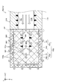
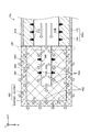
- FIG. 5 is an explanatory view showing an enlarged cross-sectional configuration of a part (a part corresponding to the X1 part of FIG. 1) of the cardiovascular model 10a included in the heart simulator 1a of the second embodiment.
- a part a part corresponding to the X1 part of FIG. 1
- the same configurations as those of the heart simulator 1 of the first embodiment described above will be omitted as appropriate.
- the cardiovascular model 10a of the second embodiment is different from the cardiovascular model 10 of the first embodiment in that the elastic body E1 is filled in the inner portion 161a and the outer portion 163a in the diffusion portion 160a, respectively.
- the diffusion portion 160a of the present embodiment is composed of an inner portion 161a and an outer portion 163a located outside the inner portion 161a.
- the inner portion 161a is a bottomed tubular body having a lumen 160L, similarly to the inner portion 161 of the first embodiment, and the lumen 160L communicates with the lumen 110L of the main branch portion 110.
- the inner portion 161a is formed by the inner porous body P61 and the elastic body E1 which is an elastic member. More specifically, in the inner portion 161a, each pore of the inner porous body P61 is filled with the elastic body E1.
- the elastic body E1 include elastic materials such as PVA, an elastomer containing polyurethane, and rubber.
- the elastic modulus of the elastic body E1 is, for example, 0.01 MPa or more and 1.5 MPa or less, more preferably 0.3 MPa or more and 0.5 MPa or less.
- the elastic modulus of the elastic material affects the above-mentioned flow resistance. That is, the larger the elastic modulus of the elastic material, the higher the flow resistance when the fluid enters the porous body containing the elastic material and is discharged to the outside of the porous material containing the elastic material. In other words, the higher the elastic modulus of the elastic body, the higher the flow resistance.
- the elastic coefficient of the elastic body E1 is such that the stress in the elastic deformation of the elastic body E1 is the fluid of the fluid. It is preferably a value smaller than the pressure.
- the elastic modulus of the elastic body E1 can be adjusted by, for example, the type of elastic material, the concentration of the elastic material in the solvent, and the like.
- the outer portion 163a is a bottomed cylindrical body located outside the inner portion 161a as in the outer portion 163 of the first embodiment, and the inner side surface S62 of the outer portion 163a is formed on the outer surface S61 of the inner portion 161a. Are in contact.
- the outer portion 163a is formed by the outer porous body P63 and the elastic body E1. More specifically, similarly to the inner portion 161a, in the outer portion 163a, each pore of the outer porous body P63 is filled with the elastic body E1.
- the elastic body E1 contained in the outer portion 163a is the same elastic material as the elastic body E1 contained in the inner portion 161a, and the elastic modulus of the elastic body E1 is substantially the same.
- the above-mentioned diffusion unit 160a can be created by, for example, the following method. First, an inner porous body P61 having a recess having an inner diameter of the same diameter as the inner cavity 160L and a core metal having an outer diameter having the same diameter as the inner cavity 160L arranged in the concave portion, and an inner porous body. An outer porous body P63 having a recess having an inner diameter equal to the outer diameter of the body P61 is prepared. Next, the inner porous body P61 is arranged in the recess of the outer porous body P63 (preparation of the diffuser precursor).
- the elastic body E1 is filled in the enlarged diameter portion precursor thus prepared (preparation of the diffusion portion 160a).
- the filling of the elastic body E1 is carried out, for example, by pouring an elastic material such as PVA, a polyurethane-containing elastomer, or rubber that has been liquefied by dissolving it in a solvent or the like (for example, water) into the enlarged diameter portion precursor. can do.
- the diffusion portion 160a can be produced by removing the core metal from the enlarged diameter portion precursor filled with the elastic body E1.
- the elastic body E1 may be filled in the enlarged diameter portion precursor by immersing the enlarged diameter portion precursor in the liquid elastic material.
- the method for producing the diffusion portion 160a is not limited to the above method.
- the inner porous body P61 and the outer porous body P63 are filled with the elastic body E1 (inner portion 161a and outer portion 163a, respectively). (Manufacturing), it can be manufactured by arranging the inner portion 161a in the recess of the outer portion 163a.
- FIG. 6 is an explanatory diagram showing the state of diffusion of the contrast medium CA.
- 6 (A) and 6 (C) show the state of the diffusion portion 160a when the pressure in the fluid flow path is low
- FIG. 6 (B) shows the state of the diffusion portion 160a when the pressure in the fluid flow path is high. It shows the situation.
- FIG. 6 shows the diffusion of the contrast medium CA in the inner portion 161a of the diffusion portion 160a, but the same is true for the outer portion 163a.
- the pores of the inner porous body P61 are filled with the elastic body E1.
- FIG. 6B shows.
- the elastic body E1 is compressed in the direction indicated by the arrow in the drawing, and the inner porous body P61 is deformed, so that fine voids are formed between the inner porous body P61 and the pores of the inner porous body P61. Can be generated, and each pore of the inner porous body P61 can be opened. Therefore, as shown in FIG. 6B, the contrast agent CA can be more finely diffused and discharged from each of the opened pores.
- the appearance of the shading of the contrast image (diffusion and disappearance image of the contrast agent) in the X-ray perspective image obtained when the contrast agent is used can be made closer to the actual blood vessel.
- the pressure in the cardiovascular model 10a (for example, the lumen 110L of the main branch 110) becomes low again, so that the elastic body E1 becomes as shown in FIG. 6C.
- Each pore of the inner porous body P61 is in a sealed state. Therefore, when the heart simulator 1a and the cardiovascular model 10a (blood vessel model) are used in a wet state immersed in a fluid (water, physiological saline, etc.), the fluid or contrast agent CA that fills the periphery of the blood vessel model is inside. It is possible to suppress backflow from each pore of the porous body P61 into the fluid flow path (for example, the lumen 110L of the main branch portion 110).
- the contrast agent CA that has entered the inner porous body P61 is more reliably discharged to the outside of the inner porous body P61 (that is, the outer porous body P63). be able to.
- the contrast agent CA that has penetrated into the outer porous body P63 can be more reliably discharged to the outer porous body P63 (that is, the diffusion portion 160a). .. That is, in the present embodiment, since it is reduced that the contrast agent CA remains inside the diffusion portion 160a, the diffusion portion 160a is less likely to be contaminated by the contrast agent CA. Therefore, the diffusion portion 160a (or the cardiovascular model 10a) can be reused.
- the pore diameter of the outer porous body P63 forming the outer portion 163a is smaller than the pore diameter of the inner porous body P61 forming the inner portion 161a. Further, the elastic moduli of the elastic body E1 filled in the inner portion 161a and the outer portion 163a are substantially the same. Therefore, the flow resistance F63a in the outer portion 163a is higher than the flow resistance F61a in the inner portion 161a.
- the cardiovascular model 10a of the present embodiment has elastic bodies in both pores of the outer porous body P63 in the outer portion 163a and the inner porous body P61 in the inner portion 161a in the diffusion portion 160a. E1 is filled.
- the pores of the porous bodies P61 and P63 of the inner portion 161a and the outer portion 163a are filled with the elastic body E1, so that the pressure in the lumen 110L is reached. While the pressure is low, the pores of the porous bodies P61 and P63 are sealed, and when the pressure in the lumen 110L increases due to the inflow of the contrast medium CA, the pores of the porous bodies P61 and P63 are opened. be able to.
- the contrast medium CA can be diffused and discharged more finely, and the appearance of the shading of the contrast medium (diffusion and disappearance image of the contrast medium) in the X-ray perspective image obtained when the contrast medium is used in an actual clinical setting can be seen. It can be closer to the contrast-enhanced image observed in actual clinical practice. Further, since the contrast medium CA that has entered the diffusion section 106a is more reliably discharged to the outside of the diffusion section 160a due to the elasticity of the elastic body E1, the contrast medium CA is suppressed from remaining in the diffusion section 160a. As a result, the diffusion unit 160a can be reused.
- the cardiovascular model 10a when used in a wet state immersed in a fluid (water, physiological saline, etc.), the fluid filling the periphery of the cardiovascular model 10a enters from the pores of the porous bodies P61 and P63. It is possible to suppress backflow into the cavity 110L.
- a fluid water, physiological saline, etc.
- FIG. 7 is an explanatory view showing an enlarged cross-sectional configuration of a part (a part corresponding to the X1 part of FIG. 1) of the cardiovascular model 10b included in the heart simulator 1b of the third embodiment.
- a part a part corresponding to the X1 part of FIG. 1
- the same configurations as those of the heart simulators 1 and 1a of the first embodiment and the second embodiment described above will be omitted as appropriate.
- the outer portion 163b constituting the diffusion portion 160b is formed of the outer porous body P63b, and the outer portion 163b is filled with the elastic body E3. 2 It is different from the cardiovascular model 10a of the embodiment.
- the diffusion portion 160b of the present embodiment is composed of an inner portion 161a and an outer portion 163b located outside the inner portion 161a.
- the outer portion 163b is a bottomed cylindrical body located outside the inner portion 161a, similarly to the outer portion 163a of the second embodiment, and the inner side surface S62 of the outer portion 163b is formed on the outer surface S61 of the inner portion 161a. Are in contact.
- the outer portion 163b is formed by the outer porous body P63b and the elastic body E3. More specifically, similarly to the inner portion 161a, in the outer portion 163b, each pore of the outer porous body P63b is filled with the elastic body E3.
- the outer porous body P63b forming the outer portion 163b is the same as the inner porous body P61 forming the inner portion 161a.
- the forming material and pore diameter of the outer porous body P63b are the same as or substantially the same as the forming material and pore diameter of the inner porous body P61, respectively.
- the elastic body E3 filled in the outer porous body P63b is different from the elastic body E1 filled in the inner porous body P61. That is, the elastic body E3 is an elastic material such as PVA, an elastomer containing polyurethane, and rubber, like the elastic body E1, but the elastic modulus of the elastic body E3 is the type of elastic material and the elastic material in the solvent. It is different from the elastic modulus of the elastic body E1 due to the difference in the concentration and the like.
- the elastic modulus of the elastic body E3 is higher than the elastic modulus of the elastic body E1.
- the elastic modulus of the elastic body E3 is, for example, 0.01 MPa or more and 1.5 MPa or less, more preferably 0.3 MPa or more and 0.5 MPa or less.
- the elastic coefficient of the elastic body E3 is the elastic deformation of the elastic body E3 because the fluid supplied to the cardiovascular model 10b is surely discharged from the outer portion 163b, similarly to the elastic body E1.
- the stress is preferably a value smaller than the fluid pressure of the fluid.
- the pore diameter of the outer porous body P63b forming the outer portion 163b is substantially the same as the pore diameter of the inner porous body P61 forming the inner portion 161a.
- the elastic modulus of the elastic body E3 filled in the outer portion 163b is higher than the elastic modulus of the elastic body E1 filled in the inner portion 161a. Therefore, the flow resistance F63b in the outer portion 163b is higher than the flow resistance F61a in the inner portion 161a.
- both the pores of the inner porous body P61 in the inner portion 161a and the outer porous body P63b in the outer portion 163b are formed.
- Elastic bodies E1 and E3 are filled.
- the elastic modulus of the outer porous body P63 is higher than the elastic modulus of the inner porous body P61.
- the higher the elastic modulus of the elastic body the higher the flow resistance in the porous body filled with the elastic body. Therefore, according to the cardiovascular model 10b of the present embodiment, the flow resistance F63b in the outer portion 163b is higher than the flow resistance F61a in the inner portion 161a.
- the cardiovascular model 10b of the present embodiment X-rays obtained when a contrast agent is used by adjusting the elastic modulus of the elastic body E3 in the outer portion 163b and the elastic modulus of the elastic body E1 in the inner portion 161a.
- the appearance of the shading of the contrast image confirmed in the actual clinical X-ray fluoroscopic image (specifically, the appearance in which the contrast agent spreads along the arterioles and then diffuses into the venules and disappears).
- FIG. 8 is an explanatory view showing an enlarged cross-sectional configuration of a part (a part corresponding to the X1 part of FIG. 1) of the cardiovascular model 10c provided in the heart simulator in the modified example.
- a part a part corresponding to the X1 part of FIG. 1
- the same configurations as those of the heart simulators 1, 1a and 1b of the first embodiment, the second embodiment and the third embodiment described above will be omitted as appropriate. do.
- the cardiovascular model 10c of the present modification is first carried out in that the main branch portion 110c is composed of a main body portion 111 having high slipperiness and a coat layer 113 having a higher elastic modulus than the main body portion 111. It differs from the cardiovascular model 10 in morphology.
- the main body 111 is an example of a flow path forming portion within the scope of claims.
- the main body 111 is a tubular body having a lumen 110L, and forms a fluid flow path extending in the long axis direction.
- the forming material of the main body portion 111 can be a soft material having X-ray transparency, similarly to the forming material of the main branch portion 110 of the first embodiment.
- the coat layer 113 is arranged on the outer periphery of the main body 111 so as to coat the main body 111. More specifically, the inner peripheral surface of the coat layer 113 is in contact with the outer peripheral surface of the main body 111.
- the material for forming the coat layer 113 can be an elastic material having X-ray transparency and having an elastic modulus higher than that of the material for forming the main body 111.
- the material for forming the coat layer 113 examples include synthetic resins such as polyvinyl alcohol (PVA), polyurethane (PU), silicon, polyamide (PA), polyethylene (PE), and polyvinyl chloride (PVC).
- PVA polyvinyl alcohol
- PU polyurethane
- PA polyamide
- PE polyethylene
- PVC polyvinyl chloride
- the coat layer 113 is arranged on the entire outer peripheral surface of the main body 111, but the present invention is not limited to this, and the coat layer 113 may be arranged on a part of the outer peripheral surface of the main body 111.
- the method of arranging the coat layer 113 on the main body 111 is not particularly limited, and a conventionally known method (for example, dip coating) can be used.
- the highly flexible main branch 110c is formed of the main body 111 and the elastic material having an elastic modulus higher than that of the material forming the main body 111. It is composed of and. Therefore, the elastic modulus of the main branch portion 110c can be adjusted by the coat layer 113.
- FIG. 9 is an explanatory view showing an enlarged cross-sectional configuration of a part of the cardiovascular model 10d (the part corresponding to the X2 part of FIG. 1) in another modified example.
- the same configurations as those of the above-described first embodiment, second embodiment, third embodiment and the modified examples of the heart simulators 1, 1a and 1b will be described. Is omitted as appropriate.
- the cardiovascular model 10d of this modified example is different from the cardiovascular model 10 of the first embodiment in that the main branch portion 110d is provided with the slit 110S.
- the main branch portion 110d is an example of a flow path forming portion within the scope of claims.
- the main branch portion 110d is provided with the slit 110S.
- the slit 110S is formed in the main branch portion 110d.
- the slit 110S has a shape such as a linear shape, a wedge shape, a round shape, or a polygonal shape, and is formed along the heart model.
- the formation position, shape and number of the slits 110S are not particularly limited.
- the main branch portion 110d is provided with a slit 110S. Therefore, the pressure inside the pipe F10 at the main branch portion 110d can be adjusted. That is, the in-pipe pressure F10 in the main branch portion 110d becomes low in the portion where the slit 110S is formed.
- the actual blood flow resistance in a coronary artery is generally high on the proximal side and low on the distal side.
- the intraductal pressure of the main branch in the actual coronary artery is generally high on the proximal side and low on the distal side.
- the slit 110S may be formed so that the intraductal pressure F10 on the proximal end side of the main branch 110d is higher than the intraductal pressure F10 on the distal end side. ..
- the main branch portion 110d simulating the above characteristics can be obtained. ..
- the “intra-tube pressure” is a simulation of human blood pressure, and for example, a pressure gauge can be connected to the main branch portion 110d for measurement.
- the pressure inside the pipe can be roughly calculated from the flow velocity hydrodynamically.
- FIG. 10 is an explanatory diagram schematically showing the configuration of the heart simulator 1e in another modified example.
- the same configurations as those of the above-described first embodiment, second embodiment, third embodiment and modified heart simulators 1, 1a and 1b will be described. The description will be omitted as appropriate.
- the main branch portion 110e does not include the diffusion portion 160, and the side branch portion 120e is formed of a porous body. It is different from the cardiovascular model 10 of.
- the side branch portion 120e is an example of a diffusion portion within the scope of claims.
- the main branch portion 110e of this modified example is a bottomed tubular body having a lumen of 160 L. More specifically, the main branch portion 110e is integrally formed of the same material as the main branch portion 110 described above.
- the side branch portion 120e of this modified example is formed of a porous body.
- the side branch portion 120e functions as a diffusion portion. Therefore, in the cardiovascular model 10e of this modified example, a diffusion portion is provided at the branch portion 140 including the side branch portion 120e.
- the side branch portion 120e has the same configuration as the diffusion portion 160 of the first embodiment. That is, the side branch portion 120e is formed by an inner portion formed by the inner porous body and an outer portion formed by the outer porous body.
- the forming material and pore size of the inner porous body and the outer porous body are the same as those of the inner porous body P61 and the outer porous body P63 described above.
- the side branch portion 120e is formed by the above-mentioned diffusion portion, so that the branch portion 140 includes the diffusion portion. Therefore, according to the cardiovascular model 10e, it is possible to simulate the shading of the contrast image in the X-ray fluoroscopic image obtained when the contrast medium is used in the actual clinical field at the bifurcation portion 140.
- the blood vessel model provided with the diffusion portion is adopted as the cardiovascular model, but the present invention is not limited to this.
- the above blood vessel model may be adopted as a cerebrovascular model, a liver blood vessel model, a lower limb blood vessel model, or the like.
- the diffusion portion 160 of the first embodiment is assumed to be a bottomed cylindrical body, but the present invention is not limited to this, and other shapes may be used. Further, in the first embodiment, a configuration in which the diffusion portion 160 has a lumen 160L is adopted, but the present invention is not limited to this. For example, a configuration in which the diffusion portion 160 does not have a lumen 160L, that is, a configuration in which the diffusion portion 160 is a medium substance formed of a porous body may be adopted.
- the diffusion portion 160 of the first embodiment is not limited to the two-layer structure formed of the porous body, and a multi-layer structure of three or more layers may be adopted. In such a configuration, it is preferable to adopt a configuration in which the flow resistance of each layer in the multilayer structure increases toward the outside of the diffusion portion 160. On the other hand, a single-layer structure may be adopted for the diffusion unit 160. In such a configuration, the flow resistance in the diffusion portion 160 can be realized by making the pore diameter of the outer portion of the diffusion portion 160 smaller than the pore diameter of the inner portion.
- the configuration in which the inner surface S62 of the outer portion 163 is in contact with the outer surface S61 of the inner portion 161 is adopted, but the present invention is not limited to this, and the inner surface surface of the outer portion 163 is not limited to this.
- a configuration in which S62 and the outer surface S61 of the inner portion 161 are not in contact with each other, that is, a configuration in which a space exists between the inner portion 161 and the outer portion 163 may be adopted.
- the inner porous body P61 forming the inner portion 161 and the outer porous body P63 forming the outer portion 163 may be formed of different porous materials. In such a configuration, it is preferable to use a forming material having better drainage than the forming material of the inner porous body P61 for the outer porous body P63.
- the main branch portion 110 may be formed of a porous body. According to the cardiovascular model having such a configuration, by forming the main branch portion with the porous body, it functions as a diffusing part that diffuses the fluid flowing through the lumen 110L from the pores of the porous body and discharges it to the outside. Can be made to.
- the pipe pressure F160 (see FIG. 4) in the diffusion portion 160 can be lower than the pipe pressure F10 in the main branch portion 110. This is to prevent the fluid supplied to the cardiovascular model 10 from being excessively leached in the main branch 110 where the intraductal pressure is low.
- the contrast medium supplied to the cardiovascular model 10 is reduced from being discharged to the outside at the main branch portion 110, and the contrast medium is spread to the diffusion portion 160.
- the contrast medium can be diffused to a certain concentration (flow rate) in the diffusing portion 160 and discharged. Therefore, it is possible to provide a blood vessel model in which the X-ray fluoroscopic image obtained when the contrast medium is used in an actual clinical setting is approximated to the contrast image blood vessel observed in the actual clinical practice.
- the adjustment of the pressure inside the pipe can be realized, for example, by making the pore size of the porous body forming the main branch portion 110 smaller than the pore diameter of the porous body forming the diffusion portion 160.
- the flow resistance F63a in the outer portion 163a may be larger than the flow resistance F61a in the inner portion 161a.
- the elastic body filled in 163a may be a different elastic material.
- the elastic modulus of the elastic body filled in the outer portion 163a is preferably higher than the elastic modulus of the elastic body filled in the inner portion 161a.
- a configuration in which the elastic body E1 is filled only in the outer portion 163a may be adopted.
- Heart simulator 1a Heart simulator 1b: Heart simulator 1e: Heart simulator 10: Cardiovascular model 10a: Cardiovascular model 10b: Cardiovascular model 10c: Cardiovascular model 10d: Cardiovascular model 10e: Cardiovascular model 20: Cardiac model 100: Introductory part 110: Main branch part 110L: Lumen 110S: Slit 110c: Main branch part 110d: Main branch part 110e: Main branch part 111: Main body part 113: Coat layer 120: Side branch part 120e: Side branch part 130: Connection Part 140: Branch part 160: Diffusion part 160L: Lumen 160a: Diffusion part 160b: Diffusion part 161: Inner part 161a: Inner part 163: Outer part 163a: Outer part 163b: Outer part E1: Elastic body E3: Elastic body P61 : Inner porous body P63: Outer porous body P63b: Outer porous body S1: Surface S60: Inner side surface S61: Outer surface S62: Inner side surface S63: Outer surface
Landscapes
- Engineering & Computer Science (AREA)
- General Physics & Mathematics (AREA)
- Theoretical Computer Science (AREA)
- Physics & Mathematics (AREA)
- Educational Technology (AREA)
- Educational Administration (AREA)
- Business, Economics & Management (AREA)
- Medicinal Chemistry (AREA)
- Computational Mathematics (AREA)
- Algebra (AREA)
- Mathematical Analysis (AREA)
- Mathematical Optimization (AREA)
- Mathematical Physics (AREA)
- Pure & Applied Mathematics (AREA)
- Health & Medical Sciences (AREA)
- Medical Informatics (AREA)
- General Health & Medical Sciences (AREA)
- Chemical & Material Sciences (AREA)
- Instructional Devices (AREA)
- Apparatus For Radiation Diagnosis (AREA)
Abstract
造影剤使用時に得られるX線透視画像を実際の血管に近似させた血管モデルを提供する。 血管モデルは、血管モデルの長軸方向に延びる流体流路を形成する流路形成部と、流路形成部に接続し、かつ、細孔を有する多孔質体により形成された拡散部とを備える。拡散部は、内側部分と、内側部分の外側に位置する外側部分とを有する。長軸方向において、外側部分における流れ抵抗は、内側部分における流れ抵抗より高い。
Description
本明細書に開示される技術は、血管モデルに関する。
臨床でのカテーテル等を用いた治療または検査を模擬するために、実際の血管を模した血管モデル(模擬血管等)を備えたシミュレータが使用されている。このようなシミュレータ等に備える模擬血管等の形成材料として、例えば、多孔質体を備える点が開示されている(例えば、特許文献1参照)。
臨床でのカテーテル等を用いた治療または検査では、血流速度や血液の粘性といった循環動態や、血管の閉塞状態等を把握するために、血管造影が用いられることがある。血管造影では、血管内に挿入されたカテーテルからX線透過度の低い造影剤を注入して、X線撮影を行う。術者は、得られたX線透視画像(静止画像または動画像、「シネ画像」とも呼ばれる)におけるコントラストの変化から、造影剤の流れの様子を観察することで、循環動態や血管状態を目視にて確認することができる。
血管モデルを使用したX線透視画像における造影剤の流れの様子を、実際の臨床上で確認される造影剤の流れの様子と近似させるべく、種々の血管モデルが提案されている。例えば、血管モデルと実際の人体との構造の違いにより、血管モデルを使用したX線透視画像にのみ造影剤が撮像される部分において、当該造影剤の濃度がX線透視画像に撮像されない濃度になるまで当該造影剤を希釈することにより、臨床上の造影剤の拡散像を模擬した血管モデル(模擬人体)が開示されている(例えば、特許文献2参照)。
従来の血管モデルでは、造影剤の流れを実際の臨床上でのX線透視下において観察される拡散像に近似させるべく向上の余地がある。
本明細書では、上述した課題を解決することが可能な技術を開示する。
本明細書に開示される技術は、例えば、以下の形態として実現することが可能である。
(1)本明細書に開示される血管モデルは、血管モデルであって、前記血管モデルの長軸方向に延びる流体流路を形成する流路形成部と、前記流路形成部に接続し、かつ、細孔を有する多孔質体により形成された拡散部と、を備え、前記拡散部は、内側部分と、前記内側部分の外側に位置する外側部分とを有し、前記長軸方向において、前記外側部分における流れ抵抗は、前記内側部分における流れ抵抗より高い。本血管モデルでは、上記流路形成部が、細孔を有する多孔質体により形成された拡散部を備える。このため、多孔質体の細孔から、流体流路を流れる流体(例えば、造影剤)を拡散させつつ外部へ排出することができる。換言すれば、多孔質体により形成された拡散部は、流体流路に流れ込んだ造影剤の圧力及び流速を分散させる拡散流路(緩衝流路)として機能する。拡散部に流れ込んだ造影剤は、拡散部において流れ抵抗の低い部分から外部へ排出される。本血管モデルでは、拡散部が、内側部分と、内側部分の流れ抵抗より高い流れ抵抗を有する外側部分とを有する。このため、拡散部に流れ込んだ造影剤は、まず、拡散部のうち流れ抵抗の低い内側部分に充填され、その後、流れ抵抗のより高い外側部分へと進入し、拡散部の外部へ排出される。このため、上記造影剤は、拡散部における外側部分の外表面全体から略均一に外部へ拡散、排出される。また、拡散部が有する外側部分の流れ抵抗が高いため、上記造影剤は外部へ排出される際に、より細かく拡散される。このため、本血管モデルでは、造影剤使用時に得られるX線透視画像において、実際の臨床上のX線透視画像で確認される造影剤の濃淡の様子(具体的には、造影剤が細動脈に沿って拡がったのち細静脈に拡散して消える様子)を模擬することができる。このため、実際の臨床現場において造影剤使用時に得られるX線透視画像を実際の臨床上で観察される造影像に近似させた血管モデルを提供することができる。
(2)上記血管モデルにおいて、前記拡散部は、前記多孔質体として、前記外側部分を構成する第1の多孔質体と、前記内側部分を構成する第2の多孔質体と、を備える構成としてもよい。換言すれば、本血管モデルにおいて、拡散部が、外側部分と内側部分とから構成される別体構成であってもよい。本血管モデルによれば、拡散部を容易に作製することができるとともに、外側部分および内側部分の組合せを容易に変更することができる。
(3)上記血管モデルにおいて、前記拡散部は、前記流路形成部における前記流体流路に開口する一端を有する、有底筒状体である構成としてもよい。本血管モデルによれば、拡散部は、流体流路に開口する一端を有しており、外形上閉塞している他端を有する、有底筒状体であるため、拡散部の末端においても、実際の臨床現場において造影剤使用時に得られるX線透視画像における造影剤の濃淡の様子を模擬できる。
(4)上記血管モデルにおいて、前記外側部分における多孔質体の孔径は、前記内側部分における多孔質体の孔径より小さい構成としてもよい。多孔質体の孔径が小さいほど、多孔質体における流れ抵抗は高くなる。このため、本血管モデルでは、外側部分における多孔質体の流れ抵抗は、内側部分における多孔質体の流れ抵抗より高い。このため、本血管モデルによれば、外側部分における多孔質体の孔径および内側部分における多孔質体の孔径を調整することにより、造影剤使用時に得られるX線透視画像において、実際の臨床上でのX線透視画像で確認される造影剤の濃淡の様子(具体的には、造影剤が細動脈に沿って拡がったのち細静脈に拡散して消える様子)を模擬することができる。このため、実際の臨床現場において造影剤使用時に得られるX線透視画像を実際の臨床上で観察される造影像に近似させた血管モデルを提供することができる。
(5)上記血管モデルにおいて、前記拡散部において、前記外側部分における多孔質体と前記内側部分における多孔質体との少なくとも一方の細孔には弾性体が充填されている構成としてもよい。本血管モデルでは、拡散部において、多孔質体(外側部分の多孔質体および/または内側部分の多孔質体)の細孔には弾性体が充填されているため、流体流路内の圧力が低い間は多孔質体の各細孔を封止し、造影剤の流入によって流体流路内の圧力が高まった際には多孔質体の各細孔を開放することができる。このため、造影剤をより細かく拡散および排出することができ、実際の臨床現場において造影剤使用時に得られるX線透視画像における造影剤の濃淡の様子(造影剤の拡散および消失像)を、実際の臨床上で観察される造影像により近づけることができる。また、拡散部に進入した造影剤は、弾性体の弾力により、より確実に拡散部の外部へと排出されるため、拡散部に造影剤が残存することを抑制し、ひいては、拡散部の再利用を可能とする。また、血管モデルを流体(水や生理食塩水等)に浸した湿潤状態で使用する場合において、血管モデルの周囲を満たす流体が、多孔質体の各細孔から流体流路内へと逆流することを抑制できる。
(6)上記血管モデルにおいて、前記拡散部において、前記外側部分における多孔質体と前記内側部分における多孔質体との両方の細孔には弾性体が充填されており、前記外側部分における多孔質体の細孔に充填された弾性体の弾性率は、前記内側部分における多孔質体の細孔に充填された弾性体の弾性率より高い構成としてもよい。弾性体の弾性率が高いほど、弾性体が充填された多孔質体における流れ抵抗は高くなる。このため、本血管モデルによれば、外側部分を構成する多孔質体と、内側部分を構成する多孔質体とにおける流れ抵抗が互いに略同等である場合において、外側部分における流れ抵抗は、内側部分における流れ抵抗より高い。このため、本血管モデルによれば、外側部分における弾性体の弾性率および内側部分における弾性体の弾性率を調整することにより、造影剤使用時に得られるX線透視画像において、実際の臨床上でのX線透視画像で確認される造影剤の濃淡の様子(具体的には、造影剤が細動脈に沿って拡がったのち細静脈に拡散して消える様子)を模擬することができる。このため、実際の臨床現場において造影剤使用時に得られるX線透視画像を実際の臨床上で観察される造影像に近似させた血管モデルを提供することができる。
(7)上記血管モデルにおいて、前記流路形成部は、前記血管モデルの長軸方向に延びる管状体であり、前記拡散部は、前記管状体の先端部に設けられている構成としてもよい。本血管モデルによれば、拡散部は、流路形成部(管状体)の先端部に設けられているため、流路形成部の先端部側で、実際の臨床現場において造影剤使用時に得られるX線透視画像における造影剤の濃淡の様子を模擬できる。
(8)上記血管モデルにおいて、前記流路形成部は、前記血管モデルの長軸方向に延びる管状体であり、前記拡散部は、前記管状体が分岐する分岐部に設けられている構成としてもよい。本血管モデルによれば、拡散部は、流路形成部(管状体)が分岐する分岐部に設けられているため、分岐部で、実際の臨床現場において造影剤使用時に得られるX線透視画像における造影剤の濃淡の様子を模擬できる。
(9)上記血管モデルにおいて、前記流路形成部は、多孔質体により形成されている構成としてもよい。本血管モデルによれば、流路形成部を多孔質体により形成することによって、多孔質体の細孔から流体流路を流れる流体を拡散させつつ外部へ排出する拡散部として機能させることができる。
(10)上記血管モデルにおいて、前記拡散部における管内圧力は、前記流路形成部の管内圧力より低い構成としてもよい。本血管モデルによれば、血管モデルに供給された造影剤が、流路形成部において外部へ排出することを低減し、拡散部まで造影剤を行きわたらせ、ひいては、拡散部において造影剤を一定の濃度(流量)まで拡散させ、排出させることができる。このため、実際の臨床現場において造影剤使用時に得られるX線透視画像を実際の臨床上で観察される造影像血管に近似させた血管モデルを提供することができる。
(11)上記血管モデルにおいて、前記血管モデルの外周面の少なくとも一部分は、弾性素材によりコーティングされている構成としてもよい。本血管モデルによれば、コーティングによって、血管モデルの弾性率を調整することができる。
なお、本明細書に開示される技術は、種々の形態で実現することが可能であり、例えば、血管モデル備えるシミュレータ、それらの製造方法等の形態で実現することができる。
A.第1実施形態:
A-1.心臓シミュレータ1の構成:
図1は、第1実施形態における心臓シミュレータ1の構成を概略的に示す説明図であり、図2は、第1実施形態における心臓血管モデル10の一部分(図1のX1部)の構成を概略的に示す説明図である。図3は、第1実施形態における心臓血管モデル10の一部分(図1のX2部)の断面構成を拡大して示す説明図であり、図4は、第1実施形態における心臓血管モデル10の一部分(図1のX1部、図2)の断面構成を拡大して示す説明図である。
A-1.心臓シミュレータ1の構成:
図1は、第1実施形態における心臓シミュレータ1の構成を概略的に示す説明図であり、図2は、第1実施形態における心臓血管モデル10の一部分(図1のX1部)の構成を概略的に示す説明図である。図3は、第1実施形態における心臓血管モデル10の一部分(図1のX2部)の断面構成を拡大して示す説明図であり、図4は、第1実施形態における心臓血管モデル10の一部分(図1のX1部、図2)の断面構成を拡大して示す説明図である。
心臓シミュレータ1は、心臓と心臓の表面を巡る血管を再現するシミュレータであり、心臓血管モデル10と心臓モデル20とを備えている。より具体的には、心臓シミュレータ1は、心臓モデル20と、心臓モデル20の表面S1に配置された心臓血管モデル10とにより構成されている。このような心臓シミュレータ1によれば、心臓血管モデル10に対して造影剤を使用した際に得られるX線透視画像において、実際の臨床上でのX線透視画像で確認される造影剤の濃淡の様子を模擬することができる。なお、各図には、方向を特定するための互いに直交するXYZ軸が図示されている。X軸は心臓モデル20の左右方向(幅方向)に対応し、Z軸は心臓モデル20の高さ方向に対応し、Y軸は心臓モデル20の奥行き方向に対応する。本明細書では、便宜的に、Z軸正方向を「上方向」または「基端側」ともいい、基端側の端部を「基端部」または単に「基端」ともいう。同様に、Z軸負方向を「下方向」または「先端側」ともいい、先端側の端部を「先端部」または単に「先端」ともいう。なお、本実施形態において、心臓血管モデル10は、心臓に血液を供給するための血管である冠動脈のうち、左冠動脈を模擬した形状のみを図示しており、右冠動脈の図示を省略している。
図1に示すように、本実施形態において、心臓血管モデル10は、導入部100と、主枝部110と、側枝部120と、接続部130と、分岐部140と、拡散部160とにより構成されている。なお、以下の説明において、主枝部110と側枝部120とをまとめて「枝部110,120」ということがある。
主枝部110は、冠動脈における主要な血管を模擬している。図2および図3に示すように、主枝部110は、内腔110Lを有する管状体である。換言すれば、主枝部110は、心臓血管モデル10(具体的には、主枝部110)の長軸方向に延びる流体流路を形成している。すなわち、後述の導入部100に供給された流体は、当該流体流路を流れる。内腔110Lは、後述の拡散部160の内腔160Lに連通している。主枝部110の形成材料は、X線透過性を有する軟性素材であれば、特に限定されない。当該軟性素材として、例えば、ポリビニルアルコール(PVA)、シリコン等の合成樹脂を挙げることができる。主枝部110の形成材料は、好ましくはPVAである。PVAは、良好な親水性を有するため、液体内に浸漬された主枝部110の物性や触感を、実際の人体の血管の物性や触感に近似させることができるためである。なお、複数の主枝部110の形成材料は、互いに同じ種類であってもよく、また、異なる種類であってもよい。主枝部110は、特許請求の範囲における流路形成部の一例であり、内腔110Lは、特許請求の範囲における流体流路の一例である。
導入部100は、基端側において開口し、先端側において主枝部110に接続する管状体である。なお、心臓血管モデル10を備える心臓シミュレータ1の使用時には、導入部100から、流体(模擬血液や造影剤)を加圧しながら供給することにより、当該流体を心臓血管モデル10全体へと拡散させる。導入部100は、上述の主枝部110と同様に、X線透過性を有する軟性素材により形成されている。
側枝部120は、主枝部110から伸びる微細な血管を模擬している。側枝部120は、一端に開口部(図示せず)を有し、他端に外形上閉塞している閉塞部を有する有底管状体である。側枝部120は、上述の主枝部110と同様に、X線透過性を有する軟性素材により形成されている。本明細書において、「外形上閉塞している」とは、見かけ上において、端部が閉ざされ塞がれていることを意味する。すなわち、機能的に閉塞していることを意味するものではなく、当該端部から流体を排出することが可能である。
接続部130は、一の主枝部110と、他の枝部110,120とを接続する部分である。接続部130において、一の主枝部110の内腔110Lと、他の枝部110,120の内腔(例えば、他の主枝部110の内腔110L)とは、連通している。この接続は種々の手段で実現でき、例えば、各枝部110,120をクリップ等の留置具で留めることで実現してもよく、各枝部110,120を接着剤で固定することで実現してもよく、各枝部110,120を合成樹脂で覆うことで実現してもよい。接続部130は、一または複数の分岐部140を含んでいる。分岐部140は、実際の人体と同様に、一の主枝部110が、一または複数の枝部110,120へと分岐する部分である。
拡散部160は、内腔160Lを有する有底筒状体である(図2および図3参照)。内腔160Lは、主枝部110と接続する接続部分CPにおいて、一端が主枝部110における内腔110Lに連通(開口)しており、他端は外形上閉塞している。本実施形態において、拡散部160は、主枝部110の先端部に設けられている。換言すれば、拡散部160は、主枝部110(心臓血管モデル10)の先端部において外形上閉塞している内腔160Lを有する有底筒状体である。
図4を用いて、拡散部160の詳細構成を説明する。図4に示すように、拡散部160は、内側部161と、内側部161の外側に位置する外側部163とにより構成されている。
内側部161は、一端が開口し、他端が外形上閉塞している内腔160Lを有する有底筒状体である。換言すれば、内腔160Lは、主枝部110の内腔110Lに面する面(開口を有する一端)を除き、内側部161の内側面S60によって画定されている。上述の通り、内腔160Lは、主枝部110の内腔110Lに連通している。内側部161は、複数の細孔を有する内側多孔質体P61により形成されている。内側多孔質体P61としては、例えば、ナイロン不織布等の不織布や、例えばポリウレタンフォーム、ポリアミドフォーム、ポリエチレンフォーム、シリコンフォーム、ゴムスポンジ等の発泡体等を挙げることができる。本実施形態において、内側多孔質体P61の孔径は、例えば、0.01mm以上、5.00mm以下であり、より好ましくは、0.5mm以上、1.5mm以下である。ここで、内側多孔質体P61や、後述の外側多孔質体P63等の多孔質体における細孔の孔径や、多孔質体を構成する材料に依存する水はけの良さは、後述の流れ抵抗に影響を及ぼす。すなわち、多孔質体の孔径については、多孔質体の孔径が小さいほど、流体が多孔質体内に進入し、多孔質外へと排出する際に、流れ抵抗はより高くなる。換言すれば、多孔質体の孔径が小さいほど、流れ抵抗はより高くなる。また、多孔質体を構成する材料に依存する水はけの良さについては、多孔質体を構成する材料が、多孔質体内に供給された流体が、より容易に多孔質体外に排出可能な材料であるほど、流れ抵抗はより低くなる。換言すれば、多孔質体が、水はけの良い材料により構成されているほど、流れ抵抗はより低くなる。本実施形態の内側多孔質体P61において、各細孔の密度は、基端側(図4のZ軸正方向)から先端側(図4のZ軸負方向)にかけて略一定である。内側多孔質体P61は、特許請求の範囲における第2の多孔質体の一例である。
外側部163は、上述の通り、内側部161の外側に位置し、外側面S63を有する有底筒状体である。本実施形態において、外側部163の内側面S62は、内側部161の外側面S61に接触している。外側部163は、外側多孔質体P63により形成されている。より具体的には、外側多孔質体P63は、内側多孔質体P61と同様の材料であり、上述の不織布や発泡体等である。本実施形態において、外側多孔質体P63の孔径は、内側多孔質体P61の孔径より小さく、例えば、0.01mm以上、1.00mm以下であり、より好ましくは、0.2mm以上、0.5mm以下である。外側多孔質体P63の孔径は、外側多孔質体P63から排出される造影剤が、X線透視画像で確認されない濃度(流量)まで拡散、排出されるよう調整されることが好ましい。本実施形態の外側多孔質体P63において、各細孔の密度は、基端側(図4のZ軸正方向)から先端側(図4のZ軸負方向)にかけて略一定である。また、本実施形態において、内側部161と外側部163とは、別体に構成されている。このような拡散部160は、外側多孔質体P63で形成された外側部163の内部に、内側多孔質体P61で形成された内側部161を配置することにより、構成することができる。外側多孔質体P63は、特許請求の範囲における第1の多孔質体の一例である。
上述の通り、本実施形態の拡散部160では、外側部163を形成する外側多孔質体P63の孔径は、内側部161を形成する内側多孔質体P61の孔径より小さい。このため、外側部163における流れ抵抗F63は、内側部161における流れ抵抗F61より高い。上述の通り、多孔質体の孔径が小さいほど、流れ抵抗はより高くなる。
心臓モデル20は、実際の心臓を模擬した外形を有している。心臓モデル20は、例えば、実際の心室を模擬するように略球体状に形成することができる。心臓モデル20の形成材料としては、例えば、弾性を有するゴムや、熱可塑性エラストマー(TPE)等の合成樹脂材料等が挙げることができる。また、心臓モデル20は、実際の心臓により近似させるために、上記合成樹脂材料等により形成された略球体の表面に、模擬心筋および模擬心膜(図示せず)を備えていてもよい。より具体的には、略球体の表面を覆うように模擬心筋を備え、模擬心筋の表面を覆うように模擬心膜を備えることができる。模擬心筋の形成材料としては、例えば、X線透過性を有する軟性素材の合成樹脂(例えば、PVA、シリコン等)等を挙げることができる。また、模擬心膜の形成材料としては、例えば、ナイロン不織布等の不織布や、ポリウレタンフォーム、ポリアミドフォーム、ポリエチレンフォーム、シリコンフォーム、ゴムスポンジ等の発泡体により形成された、複数の細孔を有する多孔質体や、X線透過性を有する軟性素材(例えば、PVA、シリコン等)の合成樹脂等を挙げることができる。
本実施形態の心臓シミュレータ1は、上述の心臓モデル20に心臓血管モデル10を固定することにより作製することができる。心臓血管モデル10を心臓モデル20に固定する方法としては、特に限定されないが、例えば、シール状の固定部材(図示せず)等により、固定することができる。固定部材の形成材料としては、例えば、X線透過性を有する軟性素材の合成樹脂(例えば、PVA、シリコン、ポリウレタン、カラギナンなどの多糖類等)等を挙げることができる。なお、固定部材の設置位置や、設置個数は任意に決定することができる。固定部材は、例えば、外力及び流体流路内の圧力が他の部位と比べて高い接続部130や分岐部140や、流体流路の先端に位置する側枝部120や、拡散部160が設けられる主枝部110の先端部等の各部において配置されることが好ましい。また、固定部材は、例えば、心臓血管モデル10(例えば、主枝部110)のうち、心臓モデル20の表面S1との接触部分を除く表面全体を覆うように配置されることが好ましい。心臓血管モデル10をより確実に心臓モデル20へと固定するためである。
A-2.第1実施形態の効果:
以上説明したように、本実施形態の心臓血管モデル10は、心臓血管モデル10の長軸方向に延びる内腔110Lを形成する主枝部110と、主枝部110に接続する拡散部160とを備えている。拡散部160は、内側部161と、内側部161の外側に位置する外側部163とを有している。内側部161は、細孔を有する内側多孔質体P61により形成されており、外側部163は、細孔を有する外側多孔質体P63により形成されている。長軸方向において、外側部163における流れ抵抗F63は、内側部161における流れ抵抗F61より高い。本実施形態の心臓血管モデル10では、主枝部110が、細孔を有する多孔質体P61,P63により形成された拡散部160を備える。このため、多孔質体P61,P63の細孔から、内腔110Lを流れる流体(例えば、造影剤)を拡散させつつ外部へ排出することができる。換言すれば、多孔質体P61,P63により形成された拡散部160は、内腔110Lに流れ込んだ造影剤の圧力及び流速を分散させる拡散流路(緩衝流路)として機能する。拡散部160に流れ込んだ造影剤は、拡散部160において流れ抵抗の低い部分から外部へ排出される。本実施形態の心臓血管モデル10では、拡散部160が、内側部161と、内側部161の流れ抵抗F61より高い流れ抵抗F63を有する外側部163とを有する。このため、拡散部160に流れ込んだ造影剤は、まず、拡散部160のうち流れ抵抗の低い内側部161に充填され、その後、流れ抵抗のより高い外側部163へと進入し、拡散部160の外部へ排出される。このため、上記造影剤は、拡散部160における外側部163の外側面S63全体から略均一に外部へ拡散、排出される。また、拡散部160が有する外側部163の流れ抵抗F63が高いため、上記造影剤は外部へ排出される際に、より細かく拡散される。このため、本実施形態の心臓血管モデル10では、造影剤使用時に得られるX線透視画像において、実際の臨床上のX線透視画像で確認される造影像の濃淡の様子(具体的には、造影剤が細動脈に沿って拡がったのち細静脈に拡散して消える様子)を模擬することができる。このため、実際の臨床現場において造影剤使用時に得られるX線透視画像を実際の臨床上で観察される拡散像に近似させた心臓血管モデル10を提供することができる。また、本実施形態の心臓血管モデル10は、拡散部160が、外側部163と内側部161とから構成される別体構成である。このため、拡散部160を容易に作製することができるとともに、外側部163および内側部161の組合せを容易に変更することができる。
以上説明したように、本実施形態の心臓血管モデル10は、心臓血管モデル10の長軸方向に延びる内腔110Lを形成する主枝部110と、主枝部110に接続する拡散部160とを備えている。拡散部160は、内側部161と、内側部161の外側に位置する外側部163とを有している。内側部161は、細孔を有する内側多孔質体P61により形成されており、外側部163は、細孔を有する外側多孔質体P63により形成されている。長軸方向において、外側部163における流れ抵抗F63は、内側部161における流れ抵抗F61より高い。本実施形態の心臓血管モデル10では、主枝部110が、細孔を有する多孔質体P61,P63により形成された拡散部160を備える。このため、多孔質体P61,P63の細孔から、内腔110Lを流れる流体(例えば、造影剤)を拡散させつつ外部へ排出することができる。換言すれば、多孔質体P61,P63により形成された拡散部160は、内腔110Lに流れ込んだ造影剤の圧力及び流速を分散させる拡散流路(緩衝流路)として機能する。拡散部160に流れ込んだ造影剤は、拡散部160において流れ抵抗の低い部分から外部へ排出される。本実施形態の心臓血管モデル10では、拡散部160が、内側部161と、内側部161の流れ抵抗F61より高い流れ抵抗F63を有する外側部163とを有する。このため、拡散部160に流れ込んだ造影剤は、まず、拡散部160のうち流れ抵抗の低い内側部161に充填され、その後、流れ抵抗のより高い外側部163へと進入し、拡散部160の外部へ排出される。このため、上記造影剤は、拡散部160における外側部163の外側面S63全体から略均一に外部へ拡散、排出される。また、拡散部160が有する外側部163の流れ抵抗F63が高いため、上記造影剤は外部へ排出される際に、より細かく拡散される。このため、本実施形態の心臓血管モデル10では、造影剤使用時に得られるX線透視画像において、実際の臨床上のX線透視画像で確認される造影像の濃淡の様子(具体的には、造影剤が細動脈に沿って拡がったのち細静脈に拡散して消える様子)を模擬することができる。このため、実際の臨床現場において造影剤使用時に得られるX線透視画像を実際の臨床上で観察される拡散像に近似させた心臓血管モデル10を提供することができる。また、本実施形態の心臓血管モデル10は、拡散部160が、外側部163と内側部161とから構成される別体構成である。このため、拡散部160を容易に作製することができるとともに、外側部163および内側部161の組合せを容易に変更することができる。
また、本実施形態の心臓血管モデル10において、拡散部160は、主枝部110における内腔110Lに開口する一端を有する、有底筒状体である。本実施形態の心臓血管モデル10によれば、拡散部160は、内腔110Lに開口する一端を有しており、外形上閉塞している他端を有する、有底筒状体であるため、拡散部160の末端においても、実際の臨床現場において造影剤使用時に得られるX線透視画像における造影像の濃淡の様子を模擬できる。
また、本実施形態の心臓血管モデル10において、外側部163における外側多孔質体P63の孔径は、内側部161における内側多孔質体P61の孔径より小さい。多孔質体の孔径が小さいほど、多孔質体における流れ抵抗は高くなる。このため、本実施形態の心臓血管モデル10では、外側部163における外側多孔質体P63の流れ抵抗F63は、内側部161における内側多孔質体P61の流れ抵抗F61より高い。このため、本実施形態の心臓血管モデル10によれば、外側部163における外側多孔質体P63の孔径および内側部161における内側多孔質体P61の孔径を調整することにより、造影剤使用時に得られるX線透視画像において、実際の臨床上のX線透視画像で確認される造影像の濃淡の様子(具体的には、造影剤が細動脈に沿って拡がったのち細静脈に拡散して消える様子)を模擬することができる。このため、実際の臨床現場において造影剤使用時に得られるX線透視画像を実際の臨床上で観察される造影像に近似させた血管モデルを提供することができる。
また、本実施形態の心臓血管モデル10において、主枝部110は、心臓血管モデル10の長軸方向に延びる管状体である。また、拡散部160は、主枝部110の先端部に設けられている。本実施形態の心臓血管モデル10によれば、拡散部160は、主枝部110(管状体)の先端部に設けられているため、主枝部110の先端部側で、実際の臨床現場において造影剤使用時に得られるX線透視画像における造影像の濃淡の様子を模擬できる。
B.第2実施形態:
図5は、第2実施形態の心臓シミュレータ1aが備える心臓血管モデル10aの一部分(図1のX1部に相当する部分)の断面構成を拡大して示す説明図である。以下では、第2実施形態の心臓シミュレータ1aの構成のうち、上述した第1実施形態の心臓シミュレータ1と同一の構成については、その説明を適宜省略する。
図5は、第2実施形態の心臓シミュレータ1aが備える心臓血管モデル10aの一部分(図1のX1部に相当する部分)の断面構成を拡大して示す説明図である。以下では、第2実施形態の心臓シミュレータ1aの構成のうち、上述した第1実施形態の心臓シミュレータ1と同一の構成については、その説明を適宜省略する。
第2実施形態の心臓血管モデル10aは、拡散部160aにおいて、内側部161aおよび外側部163aにそれぞれ弾性体E1が充填されている点で、第1実施形態の心臓血管モデル10と異なっている。
上述したように、本実施形態の拡散部160aは、内側部161aと、内側部161aの外側に位置する外側部163aとにより構成されている。
内側部161aは、第1実施形態の内側部161と同様に、内腔160Lを有する有底筒状体であり、内腔160Lは、主枝部110の内腔110Lに連通している。本実施形態において、内側部161aは、内側多孔質体P61と、弾性を有する部材である弾性体E1とにより形成されている。より具体的には、内側部161aにおいて、内側多孔質体P61の各細孔には、弾性体E1が充填されている。弾性体E1としては、例えば、PVA、ポリウレタンを含むエラストマー、ゴム等の弾性材料を挙げることができる。本実施形態において、弾性体E1の弾性率は、例えば、0.01MPa以上、1.5MPa以下であり、より好ましくは、0.3MPa以上、0.5MPa以下である。ここで、弾性材料の弾性率は、上述の流れ抵抗に影響を及ぼす。すなわち、弾性材料の弾性率が大きいほど、流体が弾性材料を含む多孔質体内に進入し、弾性材料を含む多孔質外へと排出する際に、流れ抵抗はより高くなる。換言すれば、弾性体の弾性率が高いほど、流れ抵抗はより高くなる。本実施形態において、心臓血管モデル10aに供給された流体が、内側部161aから確実に排出されるために、弾性体E1の弾性率は、弾性体E1の弾性変形における応力が、当該流体の流体圧力より小さくなる値であることが好ましい。なお、弾性体E1の弾性率は、例えば、弾性材料の種類、溶媒中の弾性材料の濃度等により調整することができる。
外側部163aは、第1実施形態の外側部163と同様に、内側部161aの外側に位置する有底筒状体であり、外側部163aの内側面S62は、内側部161aの外側面S61に接触している。本実施形態において、外側部163aは、外側多孔質体P63と、弾性体E1とにより形成されている。より具体的には、内側部161aと同様に、外側部163aにおいて、外側多孔質体P63の各細孔には、弾性体E1が充填されている。本実施形態において、外側部163aに含まれる弾性体E1は、内側部161aに含まれる弾性体E1と同一の弾性材料であり、かつ、弾性体E1の弾性率も略同等である。
上述の拡散部160aは、例えば、次の方法により作成することができる。まず、内腔160Lと同径の内径を有する凹部を有し、かつ、当該凹部内に内腔160Lと同径の外径を有する芯金が配置された内側多孔質体P61と、内側多孔質体P61の外径と同径の内径を有する凹部を有する外側多孔質体P63とを準備する。次いで、外側多孔質体P63の凹部内へ、内側多孔質体P61を配置する(拡散部前駆体の作製)。このとき、内側多孔質体P61の凹部の開口部と、外側多孔質体P63の凹部の開口部とが、同じ方向に位置するよう配置する。このように作製された拡径部前駆体に、弾性体E1を充填する(拡散部160aの作製)。弾性体E1の充填は、例えば、拡径部前駆体に対して、溶媒等(例えば、水)に溶解させることにより液状としたPVA、ポリウレタンを含むエラストマー、ゴム等の弾性材料を流し込むことにより実施することができる。最後に、弾性体E1が充填された拡径部前駆体から芯金を除去することにより、拡散部160aを作製することができる。また、別の例として、上記液状とした弾性材料に、拡径部前駆体を浸漬することにより、拡径部前駆体に対する弾性体E1の充填を実施することとしてもよい。拡散部160aの作製方法は、上記方法に限定されず、例えば、まず、内側多孔質体P61と外側多孔質体P63とに、それぞれ、弾性体E1を充填し(内側部161aおよび外側部163aの作製)、外側部163aの凹部内に内側部161aを配置することにより作製することができる。
図6は、造影剤CAの拡散の様子を示す説明図である。図6(A)および(C)は、流体流路内の圧力が低い場合の拡散部160aの様子を表し、図6(B)は、流体流路内の圧力が高い場合の拡散部160aの様子を表している。なお、図6では、拡散部160aのうち内側部161aについて、造影剤CAの拡散の様子を示しているが、当該様子は、外側部163aについても同様である。本実施形態の内側部161aにおいて、内側多孔質体P61の細孔には弾性体E1が充填されている。このため、例えば、心臓血管モデル10aに模擬血液のみが供給され、心臓血管モデル10a内(例えば、主枝部110の内腔110L)の圧力が低い間は、図6(A)に示すように、弾性体E1が内側多孔質体P61の各細孔を封止状態としている。
また、心臓血管モデル10a内に造影剤CAが注入されることによって、心臓血管モデル10a内(例えば、主枝部110の内腔110L)の圧力が高まった際には、図6(B)に示すように、弾性体E1が図中において矢印を付した方向へと圧縮され、また、内側多孔質体P61が変形することで、内側多孔質体P61の各細孔との間に微細な空隙が生じ、内側多孔質体P61の各細孔を開放することができる。このため、図6(B)に示すように、開放された各細孔から、造影剤CAをより細かく拡散及び排出することができる。この結果、造影剤使用時に得られるX線透視画像における造影像の濃淡の様子(造影剤の拡散および消失像)を、実際の血管により近づけることができる。
さらに、造影剤CAの注入終了後は、再び心臓血管モデル10a内(例えば、主枝部110の内腔110L)の圧力が低くなるため、図6(C)に示すように、弾性体E1が内側多孔質体P61の各細孔を封止状態とする。このため、心臓シミュレータ1aおよび心臓血管モデル10a(血管モデル)を流体(水や生理食塩水等)に浸した湿潤状態で使用する場合において、血管モデルの周囲を満たす流体や造影剤CAが、内側多孔質体P61の各細孔から流体流路内(例えば、主枝部110の内腔110L)へと逆流することを抑制できる。また、本実施形態の内側多孔質体P61では、内側多孔質体P61内に進入した造影剤CAを、より確実に内側多孔質体P61の外部(すなわち、外側多孔質体P63)へと排出することができる。また、本実施形態の外側多孔質体P63においても、外側多孔質体P63内に侵入した造影剤CAを、より確実に外側多孔質体P63(すなわち、拡散部160a)へと排出することができる。すなわち、本実施形態では、拡散部160aの内部に造影剤CAが残存することを低減するため、拡散部160aが造影剤CAによって汚染されにくい。このため、拡散部160a(または、心臓血管モデル10a)の再利用が可能となる。
上述の通り、本実施形態の拡散部160aでは、外側部163aを形成する外側多孔質体P63の孔径は、内側部161aを形成する内側多孔質体P61の孔径より小さい。また、内側部161aおよび外側部163aに充填された弾性体E1の弾性率は略同等である。このため、外側部163aにおける流れ抵抗F63aは、内側部161aにおける流れ抵抗F61aより高い。
以上説明したように、本実施形態の心臓血管モデル10aは、拡散部160aにおいて、外側部163aにおける外側多孔質体P63と、内側部161aにおける内側多孔質体P61との両方の細孔に弾性体E1が充填されている。本実施形態の心臓血管モデル10aでは、拡散部160aにおいて、内側部161aおよび外側部163aの多孔質体P61,P63の細孔には弾性体E1が充填されているため、内腔110L内の圧力が低い間は多孔質体P61,P63の各細孔を封止し、造影剤CAの流入によって内腔110L内の圧力が高まった際には多孔質体P61,P63の各細孔を開放することができる。このため、造影剤CAをより細かく拡散および排出することができ、実際の臨床現場において造影剤使用時に得られるX線透視画像における造影像の濃淡の様子(造影剤の拡散および消失像)を、実際の臨床上で観察される造影像により近づけることができる。また、拡散部106aに進入した造影剤CAは、弾性体E1の弾力により、より確実に拡散部160aの外部へと排出されるため、拡散部160aに造影剤CAが残存することを抑制し、ひいては、拡散部160aの再利用を可能とする。また、心臓血管モデル10aを流体(水や生理食塩水等)に浸した湿潤状態で使用する場合において、心臓血管モデル10aの周囲を満たす流体が、多孔質体P61,P63の各細孔から内腔110L内へと逆流することを抑制できる。
C.第3実施形態:
図7は、第3実施形態の心臓シミュレータ1bが備える心臓血管モデル10bの一部分(図1のX1部に相当する部分)の断面構成を拡大して示す説明図である。以下では、第3実施形態の心臓シミュレータ1bの構成のうち、上述した第1実施形態および第2実施形態の心臓シミュレータ1,1aと同一の構成については、その説明を適宜省略する。
図7は、第3実施形態の心臓シミュレータ1bが備える心臓血管モデル10bの一部分(図1のX1部に相当する部分)の断面構成を拡大して示す説明図である。以下では、第3実施形態の心臓シミュレータ1bの構成のうち、上述した第1実施形態および第2実施形態の心臓シミュレータ1,1aと同一の構成については、その説明を適宜省略する。
第3実施形態の心臓血管モデル10bは、拡散部160bを構成する外側部163bが、外側多孔質体P63bにより形成されているとともに、外側部163bに弾性体E3が充填されている点で、第2実施形態の心臓血管モデル10aと異なっている。
上述したように、本実施形態の拡散部160bは、内側部161aと、内側部161aの外側に位置する外側部163bとにより構成されている。
外側部163bは、第2実施形態の外側部163aと同様に、内側部161aの外側に位置する有底筒状体であり、外側部163bの内側面S62は、内側部161aの外側面S61に接触している。本実施形態において、外側部163bは、外側多孔質体P63bと、弾性体E3とにより形成されている。より具体的には、内側部161aと同様に、外側部163bにおいて、外側多孔質体P63bの各細孔には、弾性体E3が充填されている。本実施形態において、外側部163bを形成する外側多孔質体P63bは、内側部161aを形成する内側多孔質体P61と同一である。すなわち、外側多孔質体P63bの形成材料および孔径は、内側多孔質体P61の形成材料および孔径と、それぞれ同一または略同一である。一方、外側多孔質体P63bに充填された弾性体E3は、内側多孔質体P61に充填された弾性体E1と異なる。すなわち、弾性体E3は、弾性体E1と同様に、例えば、PVA、ポリウレタンを含むエラストマー、ゴム等の弾性材料であるが、弾性体E3の弾性率は、弾性材料の種類、溶媒中の弾性材料の濃度等が異なることにより、弾性体E1の弾性率と異なる。より具体的には、弾性体E3の弾性率は、弾性体E1の弾性率より高い。本実施形態において、弾性体E3の弾性率は、例えば、0.01MPa以上、1.5MPa以下であり、より好ましくは、0.3MPa以上、0.5MPa以下である。本実施形態において、弾性体E3の弾性率は、弾性体E1と同様に、心臓血管モデル10bに供給された流体が、外側部163bから確実に排出されるために、弾性体E3の弾性変形における応力が、当該流体の流体圧力より小さくなる値であることが好ましい。
上述の通り、本実施形態の拡散部160bでは、外側部163bを形成する外側多孔質体P63bの孔径は、内側部161aを形成する内側多孔質体P61の孔径と略同一である。一方、外側部163bに充填された弾性体E3の弾性率は、内側部161aに充填された弾性体E1の弾性率より高い。このため、外側部163bにおける流れ抵抗F63bは、内側部161aにおける流れ抵抗F61aより高い。
以上説明したように、本実施形態の心臓血管モデル10bは、拡散部160bにおいて、内側部161aにおける内側多孔質体P61と、外側部163bにおける外側多孔質体P63bとの両方の細孔に、それぞれ、弾性体E1,E3が充填されている。また、外側多孔質体P63の弾性率は、内側多孔質体P61の弾性率より高い。弾性体の弾性率が高いほど、弾性体が充填された多孔質体における流れ抵抗は高くなる。このため、本実施形態の心臓血管モデル10bによれば、外側部163bにおける流れ抵抗F63bは、内側部161aにおける流れ抵抗F61aより高い。このため、本実施形態の心臓血管モデル10bによれば、外側部163bにおける弾性体E3の弾性率および内側部161aにおける弾性体E1の弾性率を調整することにより、造影剤使用時に得られるX線透視画像において、実際の臨床上のX線透視画像で確認される造影像の濃淡の様子(具体的には、造影剤が細動脈に沿って拡がったのち細静脈に拡散して消える様子)を模擬することができる。このため、実際の臨床現場において造影剤使用時に得られるX線透視画像を実際の臨床上で観察される造影像に近似させた心臓血管モデル10bを提供することができる。
D.変形例:
本明細書で開示される技術は、上述の実施形態および変形例に限られるものではなく、その要旨を逸脱しない範囲において種々の形態に変形することができ、例えば次のような変形も可能である。
本明細書で開示される技術は、上述の実施形態および変形例に限られるものではなく、その要旨を逸脱しない範囲において種々の形態に変形することができ、例えば次のような変形も可能である。
図8は、変形例における心臓シミュレータが備える心臓血管モデル10cの一部分(図1のX1部に相当する部分)の断面構成を拡大して示す説明図である。以下では、本変形例の心臓シミュレータの構成のうち、上述した第1実施形態、第2実施形態および第3実施形態の心臓シミュレータ1,1a,1bと同一の構成については、その説明を適宜省略する。
本変形例の心臓血管モデル10cは、主枝部110cが、高い滑り性を有する本体部111と、本体部111よりも弾性率の高いコート層113とから構成されている点で、第1実施形態の心臓血管モデル10と異なっている。本体部111は、特許請求の範囲における流路形成部の一例である。
本体部111は、内腔110Lを有する管状体であり、長軸方向に延びる流体流路を形成している。本体部111の形成材料は、第1実施形態の主枝部110の形成材料と同様に、X線透過性を有する軟性素材とすることができる。コート層113は、本体部111をコーティングするように、本体部111の外周に配置されている。より具体的には、コート層113の内周面は、本体部111の外周面と接触している。コート層113の形成材料は、X線透過性を有し、かつ、本体部111の形成材料が有する弾性率より高い弾性率を有する弾性素材とすることができる。コート層113の形成材料として、例えば、ポリビニルアルコール(PVA)、ポリウレタン(PU)、シリコン、ポリアミド(PA)、ポリエチレン(PE)、ポリ塩化ビニル(PVC)等の合成樹脂を挙げることができる。なお、本変形例では、コート層113は、本体部111の外周面の全体に配置されているが、これに限定されず、本体部111の外周面の一部に配置されていてもよい。
本体部111へコート層113を配置する方法としては、特に限定されず、従来公知の方法(例えば、ディップコーティング)を用いることができる。
本変形例の心臓血管モデル10cでは、柔軟性に富む主枝部110cが、本体部111と、本体部111の形成材料が有する弾性率より高い弾性率を有する弾性素材で形成されるコート層113とから構成されている。このため、コート層113によって、主枝部110cの弾性率を調整することができる。
図9は、他の変形例における心臓血管モデル10dの一部分(図1のX2部に相当する部分)の断面構成を拡大して示す説明図である。以下では、本変形例の心臓シミュレータの構成のうち、上述した第1実施形態、第2実施形態、第3実施形態および変形例の心臓シミュレータ1,1a,1bと同一の構成については、その説明を適宜省略する。
本変形例の心臓血管モデル10dは、主枝部110dが、スリット110Sを備えている点で、第1実施形態の心臓血管モデル10と異なっている。主枝部110dは、特許請求の範囲における流路形成部の一例である。
上述したように、主枝部110dは、スリット110Sを備えている。本実施形態において、主枝部110dには、スリット110Sが形成されている。スリット110Sは、線状、くさび状、丸形状、または、多角形形状等の形状で、心臓モデルに沿うように形成されている。なお、スリット110Sの形成位置、形状および個数は、特に限定されない。
本変形例の心臓血管モデル10dでは、主枝部110dは、スリット110Sを備えている。このため、主枝部110dにおける管内圧力F10を調整することができる。すなわち、主枝部110dにおける管内圧力F10は、スリット110Sが形成されている部分において低くなる。例えば、実際の冠動脈における血液の流れ抵抗は、一般に、基端側において高く、先端側において低い。換言すれば、実際の冠動脈における主枝部の管内圧力は、一般に、基端側において高く、先端側において低い。このため、このような特徴を有する実際の冠動脈を模擬すべく、主枝部110dの基端側における管内圧力F10が、先端側における管内圧力F10より高くなるよう、スリット110Sを形成してもよい。例えば、主枝部110dの基端側に形成されるスリット110Sの個数を、先端側に形成されるスリット110Sの個数より少なくすることにより、上記特徴を模擬した主枝部110dを得ることができる。本明細書において、「管内圧力」とは、ヒトの血圧を模擬したものであり、例えば、主枝部110dに圧力計を繋ぎ、測定することができる。また、流体力学的に流速から概算で管内圧力を求めることもできる。
図10は、他の変形例における心臓シミュレータ1eの構成を概略的に示す説明図である。以下では、本変形例の心臓シミュレータ1eの構成のうち、上述した第1実施形態、第2実施形態、第3実施形態および変形例の心臓シミュレータ1,1a,1bと同一の構成については、その説明を適宜省略する。
本変形例の心臓シミュレータ1eが備える心臓血管モデル10eでは、主枝部110eが拡散部160を備えていない点、および、側枝部120eが多孔質体により形成されている点で、第1実施形態の心臓血管モデル10と異なっている。側枝部120eは、特許請求の範囲における拡散部の一例である。
上述の通り、本変形例の主枝部110eは、内腔160Lを有する有底筒状体である。より具体的には、主枝部110eは、一体として、上述の主枝部110と同様の材料により形成されている。
本変形例の側枝部120eは、多孔質体により形成されている。換言すれば、本変形例では、側枝部120eが拡散部として機能している。このため、本変形例の心臓血管モデル10eは、側枝部120eを含む分岐部140において、拡散部が設けられている。側枝部120eは、第1実施形態の拡散部160と同様の構成を備えている。すなわち、側枝部120eは、内側多孔質体により形成された内側部と、外側多孔質体により形成された外側部とにより形成されている。内側多孔質体および外側多孔質体の形成材料および孔径は、上述の内側多孔質体P61および外側多孔質体P63と同様である。
本変形例の心臓血管モデル10eでは、側枝部120eが上述の拡散部により形成されていることにより、分岐部140が拡散部を含んでいる。このため、心臓血管モデル10eによれば、分岐部140で、実際の臨床現場において造影剤使用時に得られるX線透視画像における造影像の濃淡の様子を模擬できる。
第1の実施形態では、上記拡散部を備える血管モデルを心臓血管モデルに採用したが、これに限定されない。上記血管モデルを、脳血管モデル、肝臓血管モデル、下肢血管モデル等に採用してもよい。
第1実施形態の拡散部160は、有底筒状体であるとしたがこれに限定されず、他の形状であってもよい。また、第1実施形態では、拡散部160が内腔160Lを有する構成を採用したがこれに限定されない。例えば、拡散部160が内腔160Lを備えない構成、すなわち、拡散部160が多孔質体により形成される中実体である構成を採用してもよい。
第1実施形態の拡散部160は、多孔質体により形成された2層構造に限定されず、3層以上の多層構造が採用されていてもよい。このような構成において、当該多層構造における各層の流れ抵抗は、拡散部160の外側へ向かうほど高くなる構成を採用することが好ましい。一方、拡散部160に、単層構造が採用されてもよい。このような構成において、拡散部160の外側部分の孔径を、内側部分の孔径より小さくすることで、拡散部160における流れ抵抗を実現することができる。
第1実施形態の拡散部160においては、外側部163の内側面S62が、内側部161の外側面S61に接触している構成を採用したが、これに限定されず、外側部163の内側面S62と、内側部161の外側面S61とが接触していない構成、すなわち、内側部161と外側部163との間に空間が存在する構成を採用してもよい。
第1実施形態の拡散部160において、内側部161を形成する内側多孔質体P61と、外側部163を形成する外側多孔質体P63とが、異なる多孔質材料により形成されていてもよい。このような構成において、外側多孔質体P63には、内側多孔質体P61の形成材料より水はけの良い形成材料を用いることが好ましい。
第1実施形態の心臓血管モデル10において、主枝部110が、多孔質体により形成されていてもよい。このような構成の心臓血管モデルによれば、主枝部を多孔質体により形成することによって、多孔質体の細孔から内腔110Lを流れる流体を拡散させつつ外部へ排出する拡散部として機能させることができる。このような構成において、拡散部160における管内圧力F160(図4参照)が、主枝部110の管内圧力F10より低い構成とすることができる。心臓血管モデル10に供給された流体が、管内圧力の低い主枝部110において、過度に浸出することを抑制するためである。すなわち、このような構成の心臓血管モデルによれば、心臓血管モデル10に供給された造影剤が、主枝部110において外部へ排出することを低減し、拡散部160まで造影剤を行きわたらせ、ひいては、拡散部160において造影剤を一定の濃度(流量)まで拡散させ、排出させることができる。このため、実際の臨床現場において造影剤使用時に得られるX線透視画像を実際の臨床上で観察される造影像血管に近似させた血管モデルを提供することができる。上記管内圧力の調整は、例えば、主枝部110を形成する多孔質体の孔径を、拡散部160を形成する多孔質体の孔径より小さくすることにより実現することができる。
第2実施形態の拡散部160aにおいて、外側部163aにおける流れ抵抗F63aが、内側部161aにおける流れ抵抗F61aより大きい構成であればよく、例えば、内側部161aに充填されている弾性体と、外側部163aに充填されている弾性体とが、異なる弾性材料であってもよい。このような構成において、外側部163aに充填される弾性体の弾性率は、内側部161aに充填される弾性体の弾性率より高いことが好ましい。また、外側部163aにのみ弾性体E1が充填されている構成が採用されてもよい。
1:心臓シミュレータ 1a:心臓シミュレータ 1b:心臓シミュレータ 1e:心臓シミュレータ 10:心臓血管モデル 10a:心臓血管モデル 10b:心臓血管モデル 10c:心臓血管モデル 10d:心臓血管モデル 10e:心臓血管モデル 20:心臓モデル 100:導入部 110:主枝部 110L:内腔 110S:スリット 110c:主枝部 110d:主枝部 110e:主枝部 111:本体部 113:コート層 120:側枝部 120e:側枝部 130:接続部 140:分岐部 160:拡散部 160L:内腔 160a:拡散部 160b:拡散部 161:内側部 161a:内側部 163:外側部 163a:外側部 163b:外側部 E1:弾性体 E3:弾性体 P61:内側多孔質体 P63:外側多孔質体 P63b:外側多孔質体 S1:表面 S60:内側面 S61:外側面 S62:内側面 S63:外側面
Claims (11)
- 血管モデルであって、
前記血管モデルの長軸方向に延びる流体流路を形成する流路形成部と、
前記流路形成部に接続し、かつ、細孔を有する多孔質体により形成された拡散部と、を備え、
前記拡散部は、内側部分と、前記内側部分の外側に位置する外側部分とを有し、
前記長軸方向において、前記外側部分における流れ抵抗は、前記内側部分における流れ抵抗より高い、
血管モデル。 - 請求項1に記載の血管モデルであって、
前記拡散部は、前記多孔質体として、前記外側部分を構成する第1の多孔質体と、前記内側部分を構成する第2の多孔質体と、を備える、
血管モデル。 - 請求項1または請求項2に記載の血管モデルであって、
前記拡散部は、前記流路形成部における前記流体流路に開口する一端を有する、有底筒状体である、
血管モデル。 - 請求項1から請求項3までのいずれか一項に記載の血管モデルであって、
前記外側部分における多孔質体の孔径は、前記内側部分における多孔質体の孔径より小さい、
血管モデル。 - 請求項1から請求項4までのいずれか一項に記載の血管モデルであって、
前記拡散部において、前記外側部分における多孔質体と前記内側部分における多孔質体との少なくとも一方の細孔には弾性体が充填されている、
血管モデル。 - 請求項1から請求項5までのいずれか一項に記載の血管モデルであって、
前記拡散部において、前記外側部分における多孔質体と前記内側部分における多孔質体との両方の細孔には弾性体が充填されており、
前記外側部分における多孔質体の細孔に充填された弾性体の弾性率は、前記内側部分における多孔質体の細孔に充填された弾性体の弾性率より高い、
血管モデル。 - 請求項1から請求項6までのいずれか一項に記載の血管モデルであって、
前記流路形成部は、前記血管モデルの長軸方向に延びる管状体であり、
前記拡散部は、前記管状体の先端部に設けられている、
血管モデル。 - 請求項1から請求項6までのいずれか一項に記載の血管モデルであって、
前記流路形成部は、前記血管モデルの長軸方向に延びる管状体であり、
前記拡散部は、前記管状体が分岐する分岐部に設けられている、
血管モデル。 - 請求項1から請求項6までのいずれか一項に記載の血管モデルであって、
前記流路形成部は、多孔質体により形成されている、
血管モデル。 - 請求項3に記載の血管モデルであって、
前記拡散部における管内圧力は、前記流路形成部の管内圧力より低い、
血管モデル。 - 請求項1から請求項10までのいずれか一項に記載の血管モデルであって、
前記血管モデルの外周面の少なくとも一部分は、弾性素材によりコーティングされている、
血管モデル。
Applications Claiming Priority (2)
| Application Number | Priority Date | Filing Date | Title |
|---|---|---|---|
| JP2020-049079 | 2020-03-19 | ||
| JP2020049079A JP7419124B2 (ja) | 2020-03-19 | 2020-03-19 | 血管モデル |
Publications (1)
| Publication Number | Publication Date |
|---|---|
| WO2021186823A1 true WO2021186823A1 (ja) | 2021-09-23 |
Family
ID=77771764
Family Applications (1)
| Application Number | Title | Priority Date | Filing Date |
|---|---|---|---|
| PCT/JP2020/047406 Ceased WO2021186823A1 (ja) | 2020-03-19 | 2020-12-18 | 血管モデル |
Country Status (2)
| Country | Link |
|---|---|
| JP (1) | JP7419124B2 (ja) |
| WO (1) | WO2021186823A1 (ja) |
Citations (3)
| Publication number | Priority date | Publication date | Assignee | Title |
|---|---|---|---|---|
| US20100167251A1 (en) * | 2007-06-03 | 2010-07-01 | The Regents Of The University Of California | Human torso phantom for imaging of heart with realistic modes of cardiac and respiratory motion |
| JP2012068505A (ja) * | 2010-09-24 | 2012-04-05 | Terumo Corp | 模擬人体及び心臓血管モデル |
| JP2020091307A (ja) * | 2018-12-03 | 2020-06-11 | 朝日インテック株式会社 | 血管モデル及び臓器シミュレータ |
-
2020
- 2020-03-19 JP JP2020049079A patent/JP7419124B2/ja active Active
- 2020-12-18 WO PCT/JP2020/047406 patent/WO2021186823A1/ja not_active Ceased
Patent Citations (3)
| Publication number | Priority date | Publication date | Assignee | Title |
|---|---|---|---|---|
| US20100167251A1 (en) * | 2007-06-03 | 2010-07-01 | The Regents Of The University Of California | Human torso phantom for imaging of heart with realistic modes of cardiac and respiratory motion |
| JP2012068505A (ja) * | 2010-09-24 | 2012-04-05 | Terumo Corp | 模擬人体及び心臓血管モデル |
| JP2020091307A (ja) * | 2018-12-03 | 2020-06-11 | 朝日インテック株式会社 | 血管モデル及び臓器シミュレータ |
Also Published As
| Publication number | Publication date |
|---|---|
| JP7419124B2 (ja) | 2024-01-22 |
| JP2021148963A (ja) | 2021-09-27 |
Similar Documents
| Publication | Publication Date | Title |
|---|---|---|
| KR920000467B1 (ko) | 앤지오플래스티 카테테르 | |
| JP6831335B2 (ja) | バルーンカテーテル、および医療用長尺体 | |
| AU650820B2 (en) | Nylon-peba copolymer catheter | |
| US20210272480A1 (en) | Vascular model and organ simulator | |
| CN102139136B (zh) | 一种球囊扩张导管 | |
| KR102149574B1 (ko) | 벌룬 카테터 | |
| JPH0260350B2 (ja) | ||
| US20010016730A1 (en) | Apparatus for the dialysis of blood, method for fabricating the same, and method for the dialysis of blood | |
| JPH0434416B2 (ja) | ||
| CN219110581U (zh) | 药物输送装置 | |
| JP2010187878A (ja) | 管の内腔部に配置される病変モデル | |
| US20210272481A1 (en) | Organ simulator | |
| JP7419124B2 (ja) | 血管モデル | |
| JP7481202B2 (ja) | 血管モデル | |
| Matthys et al. | In vitro study of FFR, QCA, and IVUS for the assessment of optimal stent deployment | |
| JP2004275337A (ja) | バルーンカテーテル及びその製造方法 | |
| CN214762793U (zh) | 一种多孔主动脉弓造影导管 | |
| CN213789480U (zh) | 一种内壁带有润滑层的造影导管 | |
| JP2004261299A (ja) | バルーンカテーテル | |
| JP2002052083A (ja) | バルーンカテーテル | |
| CN219681445U (zh) | 一种球囊导管 | |
| JP2011027794A (ja) | 訓練用生体モデル | |
| CN223986381U (zh) | 一种介入手术的仿真血管模型套件 | |
| CN223653993U (zh) | 一种预塑型鞘管及冠状动脉造影装置、介入治疗装置 | |
| JPH09122243A (ja) | バルーンカテーテルおよびその製造方法 |
Legal Events
| Date | Code | Title | Description |
|---|---|---|---|
| 121 | Ep: the epo has been informed by wipo that ep was designated in this application |
Ref document number: 20926139 Country of ref document: EP Kind code of ref document: A1 |
|
| NENP | Non-entry into the national phase |
Ref country code: DE |
|
| 122 | Ep: pct application non-entry in european phase |
Ref document number: 20926139 Country of ref document: EP Kind code of ref document: A1 |