WO2021186723A1 - 積層造形経路生成装置、積層造形経路生成方法、および機械学習装置 - Google Patents
積層造形経路生成装置、積層造形経路生成方法、および機械学習装置 Download PDFInfo
- Publication number
- WO2021186723A1 WO2021186723A1 PCT/JP2020/012501 JP2020012501W WO2021186723A1 WO 2021186723 A1 WO2021186723 A1 WO 2021186723A1 JP 2020012501 W JP2020012501 W JP 2020012501W WO 2021186723 A1 WO2021186723 A1 WO 2021186723A1
- Authority
- WO
- WIPO (PCT)
- Prior art keywords
- modeling
- path
- unit
- route
- data
- Prior art date
- Legal status (The legal status is an assumption and is not a legal conclusion. Google has not performed a legal analysis and makes no representation as to the accuracy of the status listed.)
- Ceased
Links
Images











Classifications
-
- B—PERFORMING OPERATIONS; TRANSPORTING
- B22—CASTING; POWDER METALLURGY
- B22F—WORKING METALLIC POWDER; MANUFACTURE OF ARTICLES FROM METALLIC POWDER; MAKING METALLIC POWDER; APPARATUS OR DEVICES SPECIALLY ADAPTED FOR METALLIC POWDER
- B22F10/00—Additive manufacturing of workpieces or articles from metallic powder
- B22F10/80—Data acquisition or data processing
- B22F10/85—Data acquisition or data processing for controlling or regulating additive manufacturing processes
-
- B—PERFORMING OPERATIONS; TRANSPORTING
- B23—MACHINE TOOLS; METAL-WORKING NOT OTHERWISE PROVIDED FOR
- B23K—SOLDERING OR UNSOLDERING; WELDING; CLADDING OR PLATING BY SOLDERING OR WELDING; CUTTING BY APPLYING HEAT LOCALLY, e.g. FLAME CUTTING; WORKING BY LASER BEAM
- B23K31/00—Processes relevant to this subclass, specially adapted for particular articles or purposes, but not covered by any single one of main groups B23K1/00 - B23K28/00
- B23K31/02—Processes relevant to this subclass, specially adapted for particular articles or purposes, but not covered by any single one of main groups B23K1/00 - B23K28/00 relating to soldering or welding
-
- B—PERFORMING OPERATIONS; TRANSPORTING
- B22—CASTING; POWDER METALLURGY
- B22F—WORKING METALLIC POWDER; MANUFACTURE OF ARTICLES FROM METALLIC POWDER; MAKING METALLIC POWDER; APPARATUS OR DEVICES SPECIALLY ADAPTED FOR METALLIC POWDER
- B22F10/00—Additive manufacturing of workpieces or articles from metallic powder
- B22F10/20—Direct sintering or melting
- B22F10/22—Direct deposition of molten metal
-
- B—PERFORMING OPERATIONS; TRANSPORTING
- B22—CASTING; POWDER METALLURGY
- B22F—WORKING METALLIC POWDER; MANUFACTURE OF ARTICLES FROM METALLIC POWDER; MAKING METALLIC POWDER; APPARATUS OR DEVICES SPECIALLY ADAPTED FOR METALLIC POWDER
- B22F10/00—Additive manufacturing of workpieces or articles from metallic powder
- B22F10/30—Process control
-
- B—PERFORMING OPERATIONS; TRANSPORTING
- B22—CASTING; POWDER METALLURGY
- B22F—WORKING METALLIC POWDER; MANUFACTURE OF ARTICLES FROM METALLIC POWDER; MAKING METALLIC POWDER; APPARATUS OR DEVICES SPECIALLY ADAPTED FOR METALLIC POWDER
- B22F10/00—Additive manufacturing of workpieces or articles from metallic powder
- B22F10/30—Process control
- B22F10/38—Process control to achieve specific product aspects, e.g. surface smoothness, density, porosity or hollow structures
-
- B—PERFORMING OPERATIONS; TRANSPORTING
- B22—CASTING; POWDER METALLURGY
- B22F—WORKING METALLIC POWDER; MANUFACTURE OF ARTICLES FROM METALLIC POWDER; MAKING METALLIC POWDER; APPARATUS OR DEVICES SPECIALLY ADAPTED FOR METALLIC POWDER
- B22F12/00—Apparatus or devices specially adapted for additive manufacturing; Auxiliary means for additive manufacturing; Combinations of additive manufacturing apparatus or devices with other processing apparatus or devices
- B22F12/90—Means for process control, e.g. cameras or sensors
-
- B—PERFORMING OPERATIONS; TRANSPORTING
- B33—ADDITIVE MANUFACTURING TECHNOLOGY
- B33Y—ADDITIVE MANUFACTURING, i.e. MANUFACTURING OF THREE-DIMENSIONAL [3D] OBJECTS BY ADDITIVE DEPOSITION, ADDITIVE AGGLOMERATION OR ADDITIVE LAYERING, e.g. BY 3D PRINTING, STEREOLITHOGRAPHY OR SELECTIVE LASER SINTERING
- B33Y30/00—Apparatus for additive manufacturing; Details thereof or accessories therefor
-
- G—PHYSICS
- G06—COMPUTING OR CALCULATING; COUNTING
- G06F—ELECTRIC DIGITAL DATA PROCESSING
- G06F30/00—Computer-aided design [CAD]
- G06F30/20—Design optimisation, verification or simulation
- G06F30/27—Design optimisation, verification or simulation using machine learning, e.g. artificial intelligence, neural networks, support vector machines [SVM] or training a model
-
- B—PERFORMING OPERATIONS; TRANSPORTING
- B22—CASTING; POWDER METALLURGY
- B22F—WORKING METALLIC POWDER; MANUFACTURE OF ARTICLES FROM METALLIC POWDER; MAKING METALLIC POWDER; APPARATUS OR DEVICES SPECIALLY ADAPTED FOR METALLIC POWDER
- B22F2999/00—Aspects linked to processes or compositions used in powder metallurgy
-
- B—PERFORMING OPERATIONS; TRANSPORTING
- B33—ADDITIVE MANUFACTURING TECHNOLOGY
- B33Y—ADDITIVE MANUFACTURING, i.e. MANUFACTURING OF THREE-DIMENSIONAL [3D] OBJECTS BY ADDITIVE DEPOSITION, ADDITIVE AGGLOMERATION OR ADDITIVE LAYERING, e.g. BY 3D PRINTING, STEREOLITHOGRAPHY OR SELECTIVE LASER SINTERING
- B33Y50/00—Data acquisition or data processing for additive manufacturing
- B33Y50/02—Data acquisition or data processing for additive manufacturing for controlling or regulating additive manufacturing processes
-
- G—PHYSICS
- G06—COMPUTING OR CALCULATING; COUNTING
- G06F—ELECTRIC DIGITAL DATA PROCESSING
- G06F2113/00—Details relating to the application field
- G06F2113/10—Additive manufacturing, e.g. three-dimensional [3D] printing
-
- Y—GENERAL TAGGING OF NEW TECHNOLOGICAL DEVELOPMENTS; GENERAL TAGGING OF CROSS-SECTIONAL TECHNOLOGIES SPANNING OVER SEVERAL SECTIONS OF THE IPC; TECHNICAL SUBJECTS COVERED BY FORMER USPC CROSS-REFERENCE ART COLLECTIONS [XRACs] AND DIGESTS
- Y02—TECHNOLOGIES OR APPLICATIONS FOR MITIGATION OR ADAPTATION AGAINST CLIMATE CHANGE
- Y02P—CLIMATE CHANGE MITIGATION TECHNOLOGIES IN THE PRODUCTION OR PROCESSING OF GOODS
- Y02P10/00—Technologies related to metal processing
- Y02P10/25—Process efficiency
Definitions
- the present disclosure relates to a laminated modeling path generation device for controlling a laminated modeling device that forms a modeled object by laminating molten metal, a laminated modeling path generation method, and a machine learning device.
- Patent Document 1 As a modeling method for modeling a modeled object by laminating molten metal, a step of dividing the modeled object into a laminated body along contour lines based on the shape data of the modeled object shape, and a step of dividing the modeled object into laminated bodies along contour lines. It is known to create a movement path of a welding torch based on the shape data of the obtained laminate.
- the present disclosure has been made in view of the above, and an object of the present disclosure is to obtain a laminated modeling path generator capable of generating a modeling path capable of suppressing dripping of molten metal.
- the present disclosure is a surface that constrains the position of the layer definition information and the modeling path that defines the division into layers that are the units for modeling the laminated model.
- a modeling path generator that divides the laminated model into layers so that the modeling height of the bead that forms the layer does not exceed the upper limit, and generates a modeling path that is a path for modeling the divided layers. It is provided with a modeling path correction unit that modifies the modeling path to a modeling path in which a plurality of layers are partially collectively modeled within a range in which the modeling height is within the range of the upper limit value and the lower limit value.
- the figure which shows an example of the modeling object which is modeled by a laminated modeling apparatus The figure which shows the example which divided the modeling object shown in FIG. 1 into layers along the contour line. The figure which shows the example which divided the modeling object shown in FIG. 1 into layers not along the contour line.
- the block diagram which shows the schematic structure of the laminated modeling route generation apparatus which concerns on Embodiment 1.
- a flowchart showing an operation when the modeling route generation control unit in the first embodiment receives an instruction to start modeling route generation.
- a flowchart showing an operation when the modeling path generation unit in the first embodiment receives an operation start instruction.
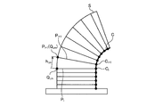
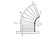
- the figure for demonstrating the setting of the subdivision layer in Embodiment 1. The figure for demonstrating the setting of the subdivision layer in Embodiment 1.
- the figure for demonstrating the setting of the subdivision layer in Embodiment 1. A flowchart showing an operation when the modeling path correction unit in the first embodiment receives an operation start instruction.
- the figure for demonstrating the extraction of the collective modeling part in Embodiment 1. The figure for demonstrating the extraction of the collective modeling part in Embodiment 1.
- the figure for demonstrating the extraction of the collective modeling part in Embodiment 1. The figure for demonstrating the extraction of the collective modeling part in Embodiment 1.
- the figure for demonstrating the extraction of the collective modeling part in Embodiment 1. The figure for demonstrating the extraction of the collective modeling part in Embodiment 1.
- the figure for demonstrating the extraction of the collective modeling part in Embodiment 1. A flowchart showing an operation when the modeling order determination unit in the first embodiment receives an operation start instruction.
- the block diagram which shows the structure of the machine learning apparatus which concerns on Embodiment 2.
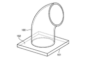
- FIG. 1 is a diagram showing an example of a modeling object that is modeled by a laminated modeling device.
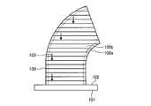
- FIG. 2 is a diagram showing an example in which the modeling object shown in FIG. 1 is divided into layers along contour lines.
- the modeling target 100 is modeled on the top surface 102 of the base 101.
- the modeling target 100 has a bent cylindrical shape.
- the cylindrical wall surface is thinly formed.
- FIG. 2 shows a state in which the modeling target 100 is divided into layers along contour lines that are parallel to the top surface 102 of the base 101.
- the cross-sectional shape of the layer viewed along the modeling direction indicated by the arrow 103 is significantly different between the upper and lower adjacent layers.
- the cross-sectional shape of the first layer 100a and the second layer 100b are significantly different. If the cross-sectional shape differs greatly between the layers, the molten metal in the upper layer portion is difficult to be supported by the lower layer portion, so that the molten metal in the upper layer portion hangs down.
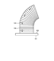
- FIG. 3 is a diagram showing an example in which the modeling object shown in FIG. 1 is divided into layers that do not follow the contour lines.
- the modeling target 100 is divided into layers in which the forming height of the bead is lowered on the inner peripheral side of the bent portion.
- the difference in the cross-sectional shape of each layer as seen along the modeling direction indicated by the arrow 104 in FIG. 3 becomes small. Therefore, it is possible to suppress the occurrence of sagging of the molten metal.
- the quality of the modeling target 100 may be deteriorated, for example, the efficiency of modeling may be lowered, or the molten metal may not be properly welded to the modeling target 100 to cause defects.
- FIG. 4 is a block diagram showing a schematic configuration of the laminated modeling route generation device according to the first embodiment.
- the laminated modeling route generation device 200 includes a modeling route generation control unit 201, a modeling route generation unit 202, a modeling route correction unit 205, a point modeling route conversion unit 206, a modeling order determination unit 207, a modeling simulation unit 208, and a modeling route storage unit. It is equipped with 210.
- a modeling route generation control unit 201 includes a modeling route generation control unit 201, a modeling route generation unit 202, a modeling route correction unit 205, a point modeling route conversion unit 206, a modeling order determination unit 207, a modeling simulation unit 208, and a modeling route storage unit. It is equipped with 210.
- the operation of each functional unit of the above-mentioned laminated modeling path generation device 200 will be briefly described, and the detailed procedure will be described later using a flowchart.
- the modeling route generation control unit 201 receives a modeling route generation start instruction from the outside of the device and controls the start of operation of each unit for generating the modeling route. Specifically, the modeling route generation control unit 201 sequentially transmits an operation start instruction to each unit of the modeling route generation unit 202, the modeling route correction unit 205, and the modeling order determination unit 207.
- a higher-level device incorporating the laminated modeling path generation device 200 is exemplified outside the device. Examples of the higher-level device include a CAM device and an automatic programming device on a modeling machine.
- the modeling route generation control unit 201 receives all the notifications of the end of operation from the modeling route generation unit 202, the modeling route correction unit 205, and the modeling order determination unit 207 for all the modeling routes. It is determined that the operation has been completed, and a notification of completion of modeling route generation is sent to the outside of the device.
- the modeling route generation unit 202 includes a provisional modeling route generation unit 203 and a subdivision layer modeling route generation unit 204.
- the modeling route generation unit 202 operates the provisional modeling route generation unit 203 and the subdivided layer modeling route generation unit 204 to generate modeling route data. Further, the generated modeling route data is stored in the modeling route storage unit 210, and the notification of the end of operation is transmitted to the modeling route generation control unit 201.
- the provisional modeling path generation unit 203 acquires the modeling path surface data, the layer definition data (layer definition information), and the modeling height range data from the outside of the apparatus in response to the operation start instruction from the modeling route generation unit 202.
- the provisional modeling path generation unit 203 generates provisional modeling path data based on the acquired modeling path surface data, layer definition data, and modeling height range data.
- the provisional modeling route generation unit 203 transmits the generated modeling route data to the subdivision layer modeling route generation unit 204.
- the modeling height range data includes data indicating an upper limit value of the modeling height of the bead and data indicating a lower limit value of the modeling height of the bead.
- the layer definition data is data that defines the division into layers, which is a unit for modeling a laminated model.
- the modeling path data generated in the present disclosure is data on the apex position, the modeling direction, and the bead modeling height in the modeling direction with respect to the apex of the polygonal line when the ideal modeling path is approximately represented by a polygonal line. It has.
- the subdivided layer modeling path generation unit 204 acquires modeling path surface data, layer definition data, and modeling height range data from the outside of the device.
- the subdivided layer modeling path generation unit 204 is the largest modeling in the bead based on the modeling path data transmitted from the provisional modeling path generation unit 203, the modeling path surface data, the layer definition data, and the modeling height range data.
- the subdivision layer is set so that the maximum modeling height does not exceed the upper limit value of the modeling height range data.
- the subdivision layer modeling path generation unit 204 generates modeling path data for the set subdivision layer.
- the subdivision layer modeling route generation unit 204 updates the modeling height data with respect to the modeling route data transmitted from the provisional modeling route generation unit 203 to set the subdivision layer.
- the subdivision layer modeling route generation unit 204 stores the modeling route data in which the subdivision layer is set and the modeling route data generated for the subdivision layer in the modeling route storage unit 210.
- the modeling route correction unit 205 receives an operation start instruction from the modeling route generation control unit 201, and acquires the modeling route data stored in the modeling route storage unit 210.
- the modeling path correction unit 205 acquires the modeling height range data from the outside of the apparatus in response to an operation start instruction from the modeling path generation control unit 201.
- the modeling route correction unit 205 receives an operation start instruction from the modeling route generation control unit 201, and confirms whether or not there is a point modeling route conversion instruction from the outside of the apparatus.
- the modeling route correction unit 205 When the modeling route correction unit 205 receives a point modeling route conversion instruction from the outside of the device, the modeling route correction unit 205 transmits the modeling route data to the point modeling route conversion unit 206 to form a bead at a discrete position. Convert to data. The modeling route correction unit 205 receives the point modeling route data from the point modeling route conversion unit 206.
- the modeling path correction unit 205 corrects the modeling path data so that the modeling height of the bead does not exceed the upper limit of the modeling height range data and does not fall below the lower limit of the modeling height range data as much as possible.
- the modeling route correction unit 205 updates the data stored in the modeling route storage unit 210 with the modified modeling route data, and transmits a notification of the end of operation to the modeling route generation control unit 201.
- the point modeling route conversion unit 206 converts the point modeling route data to perform point modeling based on the modeling route data transmitted from the modeling route correction unit 205 and the point modeling route definition data acquired from the outside of the device.
- the point modeling route conversion unit 206 transmits the point modeling route data to the modeling route correction unit 205.
- the modeling order determination unit 207 receives an operation start instruction from the modeling route generation control unit 201, and receives the modeling route data stored in the modeling route storage unit 210, the inter-modeling route definition data acquired from the outside of the device, and the movement speed data. , And the order of output of the modeling path data is determined based on the result of the simulation by the modeling simulation unit 208.
- the modeling order determination unit 207 generates inter-modeling movement route data and modeling standby time data between the modeling route data in the determined output order.
- the modeling order determination unit 207 outputs the modeling route data, the movement route data between modeling, and the modeling standby time data in the determined output order to the outside of the apparatus.
- the moving speed data is data showing the moving speed of the supply unit of the metal material that is melted to form a bead.
- the metal material supply unit that is melted to form a bead is referred to as a metal material supply unit.
- the modeling simulation unit 208 refers to the modeled object of the metal material supply unit with respect to the passage of time based on the base shape data acquired from the outside of the device, the modeling condition data, and the inter-modeling movement path data and the modeling path data for which the moving speed is specified. It is a simulator that simulates the position, the shape of the modeled object, and the heat storage state, which is the heat distribution of the modeled object.
- the base shape data is data indicating the shape of the base 101.
- the modeled object shape is a shape that combines the shape of the base 101 and the shape formed by the beads laminated on the top surface 102.
- the modeling simulation unit 208 is set to the initial state by an instruction from the modeling order determination unit 207.
- the modeling simulation unit 208 receives an inquiry from the modeling order determination unit 207, the modeling simulation unit 208 waits until the modeling starts based on the given modeling movement path data and modeling path data and the maximum allowable modeling temperature acquired from the outside of the device. Calculate the time.
- the modeling simulation unit 208 transmits the calculated waiting time to the modeling order determination unit 207.
- the modeling simulation unit 208 is instructed by the modeling order determination unit 207 to determine the position of the metal material supply unit with respect to the modeling unit based on the given inter-modeling movement path data and modeling path data, the shape of the modeled object on which the bead shape is placed, and It provides a function to transition the heat storage state of the modeled object to a simulated state.
- the modeling route storage unit 210 stores the modeling route data generated by the subdivided layer modeling route generation unit 204.
- the modeling route storage unit 210 updates the stored modeling route data with the modified modeling route data.
- FIG. 5 is a flowchart showing an operation when the modeling route generation control unit in the first embodiment receives an instruction to start modeling route generation.
- step S300 the modeling route generation control unit 201 transmits an operation start instruction to the modeling route generation unit 202, and waits for receiving a notification of the end of the operation from the modeling route generation unit 202.
- the modeling route generation control unit 201 receives the notification of the end of operation from the modeling route generation unit 202, the process proceeds to step S301.
- step S301 the modeling route generation control unit 201 transmits an operation start instruction to the modeling route correction unit 205, and waits for receiving a notification of the end of the operation from the modeling route correction unit 205.
- the process proceeds to step S302.
- step S302 the modeling route generation control unit 201 transmits an operation start instruction to the modeling order determination unit 207, and waits for receiving a notification of the end of the operation from the modeling order determination unit 207.
- the process proceeds to step S303.
- step S303 the modeling route generation control unit 201 sends a notification of the completion of modeling route generation to the outside of the device, and stops the operation.
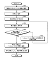
- FIG. 6 is a flowchart showing an operation when the modeling path generation unit in the first embodiment receives an operation start instruction.
- step S400 provisional modeling route data is generated in the provisional modeling route generation unit 203.
- the generated provisional modeling route data is transmitted to the subdivision layer modeling route generation unit 204.
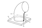
- FIG. 7 is a diagram showing an image of input data input to the provisional modeling route generation unit according to the first embodiment.
- the position of the modeling path is restricted by the modeling path surface S.
- a reference surface F 0 As information for defining the layer, a reference surface F 0 , a curve C for defining a layer whose thickness is not constant according to the shape, and a value b for specifying the thickness of the layer along the curve C. Is shown.
- the surface F 0 and the curve C intersect at the point C 0.
- the modeling path surface S corresponds to the modeling target 100 shown in FIGS. 1 to 3. Since the modeling target 100 is formed of a thin wall surface, each layer is modeled with a bead along a single line path. The neutral surface of the wall surface is used as the modeling path surface. In the case of being formed on a thick wall surface, in order to perform modeling by arranging beads along multiple paths for each layer, a corresponding modeling path is provided by giving multiple modeling path surfaces for each bead. It becomes possible to generate.
- FIG. 8 is a diagram showing an image of the definition of the boundary surfaces F 1 , F 2 , ... Between the layers for defining the layer in the first embodiment. i-th and (i + 1) th boundary surface F i of the layers is defined as follows.
- C i The i-th point on the curve C with the curve length interval as the value b from the point C 0 D 0 : The tangential direction vector of the curve C at the point C 0 (assuming
- 1)
- Di The tangential direction vector of the curve C at the point C i (assuming
- 1)
- x indicates a vector cross product operation.
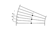
- FIG. 9 is a diagram showing modeling paths P 0 , P 1 , ... Generated in the first embodiment.
- the modeling path Pi-1 of the i-th layer is obtained as an intersection line between the modeling path surface S and the boundary surface Fi-1.
- the modeling path data in the present disclosure includes data that defines the position of the modeling path and data that defines the modeling direction and the modeling height of the bead in the modeling direction with respect to a point on the modeling path.
- FIG. 10 is a diagram showing an example of the definition of the modeling direction and the modeling height with respect to the points Qi and j on the modeling path in the first embodiment.
- Point Q i, point includes j Q i, tangential shaped path in j F i, the point in perpendicular on the section to j Q i, the point on the shaping path one on layer from j P i + 1 (Q i , the direction T i towards j), and the shaping direction j, shaping height h i, j is defined as the point Q i, j, the point P i + 1 (Q i, j) the distance between.
- the information on the modeling direction and the modeling height is used to control the attitude of the modeled object with respect to the modeling material supply unit, and to control the supply amount of the modeling material and the modeling with respect to the modeled object in the laminated modeling machine that performs modeling based on the modeling route data in the present disclosure. It is used to control the moving speed of the material supply unit.
- step S401 the subdivided layer modeling route generation unit 204 extracts the modeling route data transmitted from the provisional modeling route generation unit 203 from the lowest layer.
- step S402 the presence or absence of the extracted modeling route data is checked. If there is no modeling route data (steps S402, No), the operation of the subdivided layer modeling route generation unit 204 is terminated, and the modeling route generation unit 202 transmits a notification of the end of operation to the modeling route generation control unit 201. On the other hand, if there is modeling route data (step S402, Yes), the process proceeds to step S403.
- step S403 whether the maximum of the building height in the retrieved modeling route data exceeds the upper limit value h u of the shaped height range is checked. If the maximum of the shaped height does not exceed the upper limit value h u of the shaped height range (step S403, No), the process proceeds to step S404. On the other hand, when the maximum molding height exceeds the upper limit value h u of the shaped height range (step S403, Yes), the process proceeds to step S405.
- step S404 the extracted modeling route data is stored in the modeling route storage unit 210, and then the process returns to step S401.
- step S405 the subdivision of the layer to which the extracted modeling route data belongs is set, and the modeling route data corresponding to the subdivision is generated.
- the modeling path data corresponding to the subdivision is added to the provisional modeling path data as the one before extraction.
- it is taken out shaping path again the layer, compared with the upper limit value h u anew shaped height range is performed.
- 11 to 13 are diagrams for explaining the setting of the subdivision layer in the first embodiment. 11, the shaped path P i that is taken out, a point Q i on the molding path, shaping height is a maximum value at m, that this value exceeds the upper limit value h u of the shaped height range And.
- Layer belongs shaped path P i has been sandwiched between the boundary surface for the C i and the point C i + 1 point on the curve C for defining the layer, as shown in FIG. 12, the points C i and the point C Subdivision is set by taking points C i, 0 on the curve C between i + 1 and adding the corresponding boundary planes.
- the modeling paths Pi and 0 for the added boundary surface are generated.
- the data of the modeling direction and the modeling height are calculated in relation to the modeling path Pi + 1, and are held in the modeling path Pi, 0.
- the data of the building direction and shaping height is held in the shaped path P i is updated is calculated in relation to the shaped path P i, 0.
- FIG. 13 shows an image of the modeling route data stored in the modeling route storage unit 210 after the operation of the subdivided layer modeling route generation unit 204 is completed. Provisional shaping a route generating unit 203 in the production of shaped path data with subdivision layer shaped path generation unit 204, the generation of shaped path data maximum molding height does not exceed the upper limit value h u of the shaped height range, necessary Efficient performance can be achieved by setting subdivision layers in the portion and adding modeling path data.
- maximum shaping height of i-th layer shaped path modeling how that exploratory determine the position in the height range of the upper limit value h u becomes equal manner i + 1 th layer shaped path can also be taken, by this method, shaped path data further reduce the overall number of layers Can be generated.
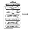
- FIG. 14 is a flowchart showing an operation when the modeling path correction unit in the first embodiment receives an operation start instruction.
- step S500 the reference modeling route data is sequentially taken out from the modeling route data storage unit 210 from the lowest layer to the upper layer.
- step S501 the presence or absence of the reference modeling route data is confirmed. If there is modeling route data as a reference (steps S501 and Yes), the process proceeds to step S502. If there is no reference modeling route data (steps S501, No), a notification of the end of the operation is transmitted to the modeling route generation control unit 201, and the operation ends.
- step S502 it is confirmed whether or not there is a point modeling route conversion instruction from the outside of the device. If there is a point modeling route conversion instruction (step S502, Yes), the process proceeds to step S503. If there is no point modeling route conversion instruction (step S502, No), the process proceeds to step S504.
- step S503 the modeling path data taken out as a reference is converted into point modeling path data for performing point modeling in which beads are formed at discrete points (discrete points) by the point modeling conversion unit 206.
- the point modeling conversion unit 206 is between the point modeling for each layer based on the modeling route data from the modeling route correction unit 205 and the point modeling target interval data included in the point modeling route definition data acquired from the outside of the device. to determine the actual distance d a.
- Point modeling conversion unit 206, shaped path generates data representing a point on the molding path at the actual distance d a, and generates a shaped path data of the point shaped based on the position of the point is generated, shaped path correction unit 205 Send to.
- step S504 a batch modeling portion that is collectively performed including modeling by the upper layer modeling path in the modeling path represented by the reference modeling path data is extracted.
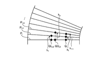
- An example of extracting the batch modeling portion will be described with reference to FIGS. 15 to 22.
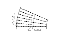
- FIGS. 15 to 18 are diagrams for explaining the case of line modeling.
- the modeling path Pi indicates a reference modeling path.
- shaping height portion of the reference of the shaped path P i is small portion than the lower limit value h l ranging shaping height is extracted as bulk molding candidate.
- Figure 16 is a graph plotting on the vertical axis the molding height to a point on the reference of the shaped path P abscissa position of a point on the i, the reference of the shaped path P i, h i data for modeling path P i portion between shows the build height modeling height data defines a point QL i, 0 and the point QL i, 1 as a portion shaped height h i is less than the lower limit value h l contained in Is extracted.
- the part where the modeling of the upper layer modeling path can be performed collectively is extracted next.
- Modeling the height h i is shaped height needed to perform collectively shaping of the upper shaped path relative to the portion below the lower limit value h l of shaped path P i of the reference in this extract is calculated, part calculated shaped height is lower than the upper limit value h u ranging shaping height is extracted.
- h i + 1 is obtained by calculating the build height needed to perform collectively layer of molding of shaped path P i + 1 by the reference of the shaped path P i, points QU i, 0 and the point QU Those portions between i, 1, shaped height h i + 1 plus the upper layer of the shaped height is below the upper limit value h u ranging shaping height, and this portion is extracted as a lump shaped portion NS.
- the portion below the lower limit value h l is further referred to as the upper layer modeling path. Extraction of the batch modeling part of is repeated. Depending on the range of the shaped height given, shaped path P i point QL i, 0 and the point QU i, 0 interval and the point of QU i, 1 and the point QL i, 1 a section of which is shown in FIG.
- the modeling height data of the modeling path data is the modeling height data required for batch modeling for the portion of the reference modeling path extracted in step S504 where the modeling of the upper layer modeling path can be performed collectively.
- the original data of the modeling route storage unit 210 is updated with the changed data.
- step S506 the upper layer modeling route data having the portion to be collectively modeled by the reference modeling path is changed to the data in which the path of the portion to be collectively modeled is deleted, and the modeling route storage unit 210 is changed by the changed data.
- the original data of is updated.
- Figure 17 is a shaped part which is shaped in bulk in shaping path P i + 1 of the upper layer with the update of the height data modeling in the reference of the shaped path P i, in modeling by the reference of the shaped path P i a moiety collectively shaped It shows the result of deleting the route.
- FIG. 18 shows the result of modifying the modeling path by taking out the reference modeling path in order from the lower layer.
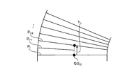
- 19 to 22 are diagrams for explaining the case of point modeling.
- reference is shaped path P i of which is intended to carry out the point shaped with intervals d a, it stuck in the one of the line shaped for the upper layer of the shaped path.
- steps S504 to S506 processing is performed in the same manner as in the case where the reference modeling path is line modeling.
- the batch modeling portion in the reference modeling path extracted in step S504 is extracted in the discrete points of point modeling as shown in FIG.
- the modeling height data of the reference modeling path is updated, and the batch in the upper layer modeling path having the portion collectively modeled by the reference modeling path.
- the path of the modeling part is deleted.
- the modeling route is corrected while converting only the reference modeling path to point modeling, so that the i + 1th layer with respect to the point QL i, 0 of the i-th layer in FIG.
- the position of the point modeling of the end in the modeling of each layer is determined with good alignment so that the point P i + 1 (QL i, 0) at the end of each layer corresponds to, and high quality modeling is possible.
- FIG. 23 is a flowchart showing an operation when the modeling order determining unit in the first embodiment receives an operation start instruction.
- step S600 the modeling order determination unit 207 instructs the modeling simulation unit 208 to initialize.
- the modeling simulation unit 208 determines the position of the modeling machine, the shape of the modeled object, and the heat distribution of the modeled object in the data showing the simulation state based on the base shape data acquired from the outside of the device and the modeling condition data. Initialize to the state before the start of modeling.
- step S601 the modeling order determination unit 207 takes out the data group of the modeling route data of the next modeling candidate from the modeling route storage unit 210.
- the modeling route data the data from the lowest layer is extracted in order from the one in the upper layer, and the modeling route data up to the range where there is no hierarchical relationship between the layers in the extracted modeling path is selected as the next modeling candidate. Take out as a thing.
- step S602 the modeling order determination unit 207 confirms the presence or absence of modeling route data of the next modeling candidate. If there is no modeling route data for the next modeling candidate (step S602, No), a notification of the end of operation is transmitted to the modeling route generation control unit 201 to end the operation of the modeling order determination unit 207. If there is modeling route data for the next modeling candidate (step S602, Yes), the process proceeds to step S603.
- step S603 the modeling order determination unit 207 transfers the modeling path data of the next modeling candidate from the end point of the modeling path in which the modeling state is finally reflected in the modeling simulation unit 208 to the start point of the modeling path of the next modeling candidate. Generate movement route data.
- the modeling order determination unit 207 gives the modeling simulation unit 208 the modeling path data of the next modeling candidate and the moving route data to the starting point of the modeling path, and is a waiting time until the start of modeling by the modeling path of the next modeling candidate. The waiting time and the cooling time required for cooling the modeled object during the waiting time are acquired from the modeling simulation unit 208.
- FIG. 24 is a flowchart showing the operation of the modeling simulation unit to which the modeling route data and the like are given from the modeling order determination unit in the first embodiment.
- step S700 the modeling simulation unit 208 internally stores data for returning to the current simulation state later.
- step S701 the modeling simulation section 208 based on the moving velocity data with the acquired moving path data provided from the molding sequence determination unit 207 from the outside of the apparatus, to reflect the state of movement by the movement path in the simulation, the time t m To get.
- time t m from the end point of the molding path in which the metal material supply unit reflecting the shaped state finally, is the time when along the movement path given to move to the start point of the shaped path of the next molding candidate ..
- step S702 the modeling simulation unit 208 initializes the cooling time t c to 0.
- step S703 the modeling simulation unit 208 is in the simulation state of the part of the modeled object shape on which the bead rides according to the modeling path, based on the modeling path data given from the modeling order determination unit 207 and the modeling condition data acquired from the outside of the device. Obtain the maximum temperature T m.
- step S704 the modeling simulation section 208, a maximum temperature T m which acquired to confirm or lower than the shaped allowable temperature T p obtained from outside the device. If the maximum temperature T m is lower than the allowable modeling temperature T p (steps S704, Yes), the process proceeds to step S706. If the maximum temperature T m is equal to or higher than the allowable modeling temperature T p (steps S704 and No), the process proceeds to step S705.
- step S705 the modeling simulation unit 208 updates the simulation state to the state after the minute time ⁇ t, increases the cooling time t c by the minute time ⁇ t, and then proceeds to step S703.
- step S706 the simulation state saved in step S700 is restored.
- step S707 the modeling simulation section 208 returns the waiting time t w and the cooling time t c which is calculated as the sum of the moving time t m and the cooling time t c to build order determining section 207, then the operation of the waiting time computation finish.
- the above is the calculation operation of the waiting time and the cooling time in the modeling simulation unit 208.
- step S604 the one with the minimum modeling waiting time acquired from each modeling route data of the next modeling candidate is selected.
- step S605 the selected modeling path data is given to the modeling simulation unit 208, and the simulation state is changed to the state after modeling by the given data.
- step S606 the movement route data generated in step S603 plus the cooling time data acquired in step S603 is added to the selected modeling route data, and the selected modeling route data is output to the outside of the apparatus. Then, the process returns to step S601.
- the above is the operation of the modeling order determination unit 207.
- the height of the modeling does not exceed the specified upper limit value and falls below the predetermined lower limit value as much as possible. It is possible to generate a modeling path that does not exist. As a result, it is possible to perform modeling at an appropriate modeling height by the output modeling path, and it is possible to prevent deterioration of modeling efficiency and quality.
- the laminated modeling path generation device 200 sets the order of the output modeling path data to the minimum modeling start based on the movement time between the modeling paths and the cooling time until the modeled object portion on which the bead rides on the modeling path drops to a specified temperature. It is determined that the waiting time is set to, and the movement route data to which the cooling time data is added is output between the modeling route data. By performing modeling based on this output data, it is possible to shorten the modeling time while avoiding shape collapse by suppressing the temperature of the portion on which the bead of the modeled object rides to a specified temperature or lower.
- FIG. 25 is a diagram showing an example of hardware that realizes the laminated modeling route generation device according to the first embodiment.
- the processor 11 is a CPU (Central Processing Unit, central processing unit, processing unit, arithmetic unit, microprocessor, microcomputer, DSP (Digital Signal Processor)), system LSI (Large Scale Integration), and the like.
- the memory 12 includes a RAM (Random Access Memory), a ROM (Read Only Memory), an EPROM (Erasable Programmable Read Only Memory), an EEPROM (registered trademark) (Electrically Erasable Programmable Read Only Memory), a hard disk drive, and the like.
- the interface circuit 13 is a circuit for the laminated modeling path generation device 200 to transfer data to and from an external device.
- Modeling route generation control unit 201 modeling route generation unit 202, provisional modeling route generation unit 203, subdivision layer modeling route generation unit 204, modeling route correction unit 205, point modeling route conversion unit 206, modeling order of the laminated modeling route generation device 200.
- the determination unit 207 and the modeling simulation unit 208 are realized by the processor 11 executing a program for operating as each of these units.
- the program is stored in the memory 12 in advance.
- the processor 11 reads the above program from the memory 12 and executes it. It is assumed that the program is stored in the memory 12 in advance, but the program is not limited to this.
- the program may be supplied to the user in a state of being written on a recording medium such as a CD (Compact Disc) -ROM or a DVD (Digital Versatile Disc) -ROM, and the user may install the program in the memory 12. ..
- the hardware that realizes the laminated modeling path generation device 200 further includes a reading device for reading a program from the recording medium. Further, a reading device may be connected to the interface circuit 13 to install the program.
- FIG. 26 is a block diagram showing the configuration of the machine learning device according to the second embodiment.
- the machine learning device 220 includes a state observation unit 221 and a learning unit 222.
- the state observing unit 221 observes the modeling accuracy of the modeling result based on the modeling route data output by the laminated modeling route generator 200, the modeling material material type data, and the modeling route data output by the laminated modeling route generator 200 as state variables. do.
- a device such as a coordinate measuring machine, a surface roughness measuring device, or an image size measuring device for the modeling accuracy of the modeling result based on the modeling path data.
- Information on the modeling accuracy may be stored in, for example, the modeling result information storage unit 211.
- the learning unit 222 determines the modeling accuracy of the modeling result based on the modeling route data according to the data set created based on the modeling route data, the modeling material material type data, and the state variable of the modeling accuracy of the modeling result based on the modeling route data. Learn the allowable modeling temperature to be satisfied.
- the allowable modeling temperature is the modeling path when the modeling simulation unit 208 calculates the cooling time, which is a component of the modeling waiting time for the modeling path, which is the basis for determining the modeling order of the modeling path in the laminated modeling path generator 200. It specifies the maximum temperature required for the part of the modeled object on which the bead rides.
- Any learning algorithm may be used as the learning algorithm used by the learning unit 222.
- Reinforcement learning is that an agent (behavior) in a certain environment observes the current state and decides the action to be taken. Agents get rewarded from the environment by choosing an action and learn how to get the most reward through a series of actions.
- Q-learning and TD-learning are known as typical methods of reinforcement learning.
- a general update formula (behavioral value table) of the behavioral value function Q (s, a) is expressed by the following mathematical formula (1).
- Equation (1) s t represents the environment at time t, a t represents the behavior in time t.
- the environment is changed to s t + 1.
- rt + 1 represents the reward received by the change of the environment
- ⁇ represents the discount rate
- ⁇ represents the learning coefficient. Note that ⁇ is in the range of 0 ⁇ ⁇ 1 and ⁇ is in the range of 0 ⁇ ⁇ 1. If you apply the Q-learning, modeling allowable temperature becomes the action a t to be input.
- the update formula represented by the formula (1) increases the action value Q if the action value of the best action a at time t + 1 is larger than the action value Q of the action a executed at time t, and vice versa. In that case, the action value Q is reduced. In other words, the action value function Q (s, a) is updated so that the action value Q of the action a at time t approaches the best action value at time t + 1. As a result, the best behavioral value in a certain environment is sequentially propagated to the behavioral value in the previous environment.
- the learning unit 222 includes a reward calculation unit and a function update unit.
- the reward calculation unit calculates the reward based on the state variable.
- the reward calculation unit calculates the reward r based on the processing accuracy of the modeling result based on the modeling route data output from the laminated modeling route generation device 200. For example, when the modeling accuracy of the modeling result based on the modeling path data is better than the desired modeling accuracy, the reward r is increased (for example, the reward of "1" is given). On the other hand, when the modeling accuracy of the modeling result based on the modeling path data is worse than the desired modeling accuracy, the reward r is reduced (for example, a reward of "-1" is given).
- the modeling accuracy of the modeling result based on the modeling route data is extracted according to a known method. For example, it is obtained by determining whether or not the value measured using a device such as a coordinate measuring machine, a surface roughness measuring device, or an image dimension measuring device is within a desired modeling accuracy.
- the function update unit updates the function for determining the allowable modeling temperature that satisfies the modeling accuracy of the modeling result based on the modeling path data according to the reward calculated by the reward calculation unit. For example, in the case of Q-learning, it is used as a function for calculating a shaped allowable temperature consistent with molding accuracy of shaping results based on modeling route data action value function Q (s t, a t) represented by Equation (1).
- reinforcement learning is applied to the learning algorithm used by the learning unit 222
- the present invention is not limited to this.
- the learning algorithm in addition to reinforcement learning, supervised learning, unsupervised learning, semi-supervised learning, and the like can also be applied.
- deep learning which learns the extraction of the feature amount itself
- other known methods such as neural networks, genetic programming, functional logic programming, and support vectors can be used.
- Machine learning may be executed according to the machine or the like.
- the machine learning device 220 is used to learn the allowable modeling temperature that satisfies the modeling accuracy of the modeling result based on the modeling path data output by the laminated modeling path generation device 200.
- the machine learning device 220 is used for laminated modeling via a network. It may be connected to the route generation device 200 and may be a device separate from the laminated modeling route generation device 200. Further, the machine learning device 220 may be built in the laminated modeling path generation device 200. Further, the machine learning device 220 may exist on the cloud server.
- the learning unit 222 may learn the allowable modeling temperature that satisfies the modeling accuracy of the modeling result based on the modeling path data according to the data set created for the plurality of laminated modeling path generation devices 200.
- the learning unit 222 may acquire a data set from a plurality of laminated modeling path generators 200 used at the same site, or from a plurality of laminated modeling machines 209 that operate independently at different sites.
- the collected data set may be used to learn the allowable modeling temperature that satisfies the modeling accuracy of the processing result based on the modeling path data.
- a machine learning device 220 that has learned the allowable modeling temperature that satisfies the modeling accuracy of the modeling result based on the modeling path data for a certain laminated modeling path generating device 200 is attached to another laminated modeling path generating device 200, and the other The allowable modeling temperature that satisfies the modeling accuracy of the modeling result based on the modeling path data may be relearned and updated with respect to the laminated modeling path generation device 200 of the above.
- the machine learning device 220 can be realized by the hardware shown in FIG. 25.
- the processor 11 reads the program from the memory 12 and executes it, it operates as the state observation unit 221 and the learning unit 222.
- the configuration shown in the above embodiments is an example, and can be combined with another known technique, can be combined with each other, and does not deviate from the gist. It is also possible to omit or change a part of the configuration.
- 100 modeling target 100a first layer, 100b second layer, 101 base, 102 top surface, 200 laminated modeling route generation device, 201 modeling route generation control unit, 202 modeling route generation unit, 203 provisional modeling route generation unit, 204 subdivided layer modeling route generation unit, 205 modeling route correction unit, 206 point modeling route conversion unit, 207 modeling order determination unit, 208 modeling simulation unit, 209 laminated modeling machine, 210 modeling route storage unit, 211 modeling result information storage unit, 220 machine learning device, 221 state observation unit, 222 learning unit.
Landscapes
- Engineering & Computer Science (AREA)
- Chemical & Material Sciences (AREA)
- Materials Engineering (AREA)
- Manufacturing & Machinery (AREA)
- Automation & Control Theory (AREA)
- Analytical Chemistry (AREA)
- Evolutionary Computation (AREA)
- Physics & Mathematics (AREA)
- Theoretical Computer Science (AREA)
- Computer Vision & Pattern Recognition (AREA)
- Artificial Intelligence (AREA)
- Medical Informatics (AREA)
- Software Systems (AREA)
- Computer Hardware Design (AREA)
- Geometry (AREA)
- General Engineering & Computer Science (AREA)
- General Physics & Mathematics (AREA)
- Mechanical Engineering (AREA)
Abstract
Description
図4は、実施の形態1にかかる積層造形経路生成装置の概略構成を示すブロック図である。積層造形経路生成装置200は、造形経路生成制御部201、造形経路生成部202、造形経路修正部205、点造形経路変換部206、造形順番決定部207、造形シミュレーション部208、および造形経路記憶部210を備える。まず、上述した積層造形経路生成装置200の各機能部の動作について簡単に説明し、詳細な手順についてはフローチャートを用いて後に説明する。
Ci:曲線C上で点C0から曲線長間隔を値bとしてとったi番目の点
D0:点C0における曲線Cの接線方向ベクトル(|D0|=1とする)
Di:点Ciにおける曲線Cの接線方向ベクトル(|Di|=1とする)
以下に実施の形態2にかかる機械学習装置を図面に基づいて詳細に説明する。なお、上記実施の形態1と同様の構成については、同様の符号を付して詳細な説明を省略する。図26は、実施の形態2にかかる機械学習装置の構成を示すブロック図である。機械学習装置220は、状態観測部221と学習部222とを備える。

Claims (7)
- 積層造形物を造形する単位となる層への分割を定義する層定義情報と造形経路の位置を制約する面である造形経路面とから、前記層を造形するビードの造形高さが上限値を超えないように前記積層造形物を前記層に分割して、分割した層を造形する経路である造形経路を生成する造形経路生成部と、
前記造形経路を前記造形高さが上限値と下限値との範囲内で複数の層を部分的に一括して造形する造形経路に修正する造形経路修正部と、を備えることを特徴とする積層造形経路生成装置。 - 前記造形経路には前記造形経路で造形するビードの造形高さ情報が付加されており、
前記造形経路修正部は、
前記造形経路の一部であって前記造形高さが前記下限値より小さい部分を一括造形候補として抽出し、
前記一括造形候補の中で前記一括造形候補の造形と前記一括造形候補の上方に隣接する前記造形経路の造形とを合わせた造形の造形高さが前記上限値を超えない部分を、一括造形部分として抽出し、
抽出した前記一括造形部分についての前記造形高さ情報を、前記一括造形候補の造形と前記一括造形候補の上方に隣接する前記造形経路の造形とを合わせた造形の造形高さに更新し、
前記一括造形部分の上方に隣接する前記造形経路の部分を前記造形経路から削除することを特徴とする請求項1に記載の積層造形経路生成装置。 - 前記造形経路生成部は、前記層定義情報と前記造形経路面とから、暫定的な造形経路である暫定造形経路を生成する暫定造形経路生成部と、
前記暫定造形経路におけるビードの最大の造形高さが前記上限値を超える前記層を選択し、前記選択した層を高さ方向に分割した細分層を設定した場合に設定した細分層の造形経路におけるビードの最大の造形高さが前記上限値を超えないように細分層を設定し、前記設定した細分層の造形経路を生成して前記選択した層の造形経路を置換する細分層造形経路生成部と、をさらに備えることを特徴とする請求項1に記載の積層造形経路生成装置。 - 前記造形経路上に離散点を設定し、前記離散点を結ぶように前記造形経路を設けて造形経路を生成する点造形経路変換部をさらに備え、
前記離散点の間の前記造形経路の長さは互いに等しく、前記離散点の間の前記造形経路の長さはあらかじめ定めた値を超えないことを特徴とする請求項1から3のいずれか1つに記載の積層造形経路生成装置。 - 造形順番決定部をさらに備え、
前記造形順番決定部は、前記造形経路を、下方の前記層から上方の前記層へと順番に取り出した際の層の上下関係がない範囲のものを次の出力候補とし、
積層記造形物が載置される土台に造形経路によるビードが乗せられた造形物の形状と時間経過に対する造形物の熱分布を模擬し、与えられた造形間移動経路による移動時間と造形経路のビードが乗る造形物の部分における最大温度を評価する造形シミュレーション部を備え、
前記次の出力候補の造形経路の各々について、最後に出力した造形経路の終点から次の出力候補の造形経路の始点までの移動経路を生成し、
生成した移動経路と所定の移動速度を基に前記造形シミュレーション部により移動時間を評価して取得し、
最後に出力した造形経路による造形後から前記移動時間が経過した時点の状態から、前記出力候補の造形経路によるビードが乗る造形物の部分の最大温度の前記造形シミュレーション部による評価を所定の経過時間を前記造形シミュレーション部に与えながら行うことでビードが乗る造形物の部分の最大温度が所定の造形許容温度まで下がるまでの冷却時間を計算し、
前記取得した移動時間と前期計算した冷却時間との和により前記出力候補の造形経路による造形を開始するまで造形待ち時間を計算し、
前記次の出力候補の造形経路の中で、前期計算した造形待ち時間が最小のものを出力する造形経路として選択し、
選択した造形経路を前記造形シミュレーション部に与えて前記造形シミュレーション部の状態を造形後の造形物の形状と熱分布の状態に更新し、選択した造形経路に対する移動経路、造形待ち時間、および造形経路を出力することを特徴とする請求項1から4のいずれか1つに記載の積層造形経路生成装置。 - 積層造形物を造形する単位となる層への分割を定義する層定義情報と造形経路の位置を制約する面である造形経路面とから、前記層を造形するビードの造形高さが上限値を超えないように前記積層造形物を層に分割して、分割した層を造形する経路である造形経路を生成する造形経路生成ステップと、
前記造形経路生成ステップで生成された前記造形経路をビードの造形高さが前記上限値と下限値の範囲内で複数の隣接する層を部分的に一括して造形する造形経路に修正する造形経路修正ステップと、を備えることを特徴とする積層造形経路生成方法。 - 積層造形経路生成装置から出力される造形経路に基づく造形結果の加工精度を満たす造形許容温度を学習する機械学習装置であって、
前記積層造形経路生成装置が出力した前記造形経路、造形材料材質種別、および前記造形経路に基づく造形結果の造形精度を状態変数として観測する状態観測部と、
前記状態変数に基づいて作成されるデータセットに従って、造形結果の造形精度を満たす造形許容温度を学習する学習部と、を備えることを特徴とする機械学習装置。
Priority Applications (6)
| Application Number | Priority Date | Filing Date | Title |
|---|---|---|---|
| JP2022508008A JP7325607B2 (ja) | 2020-03-19 | 2020-03-19 | 積層造形経路生成装置、積層造形経路生成方法、および機械学習装置 |
| CN202080098505.XA CN115279526A (zh) | 2020-03-19 | 2020-03-19 | 层叠造形路径生成装置、层叠造形路径生成方法及机器学习装置 |
| DE112020006920.6T DE112020006920T5 (de) | 2020-03-19 | 2020-03-19 | Einrichtung zur erzeugung von pfaden für additive fertigung, verfahren zur erzeugung von pfaden für additive fertigung und einrichtung für maschinelles lernen |
| PCT/JP2020/012501 WO2021186723A1 (ja) | 2020-03-19 | 2020-03-19 | 積層造形経路生成装置、積層造形経路生成方法、および機械学習装置 |
| CN202410483732.4A CN118123304A (zh) | 2020-03-19 | 2020-03-19 | 层叠造形路径生成装置、层叠造形路径生成方法及机器学习装置 |
| US17/909,757 US12280428B2 (en) | 2020-03-19 | 2020-03-19 | Additive manufacturing path generation apparatus, additive manufacturing path generation method, and machine learning apparatus |
Applications Claiming Priority (1)
| Application Number | Priority Date | Filing Date | Title |
|---|---|---|---|
| PCT/JP2020/012501 WO2021186723A1 (ja) | 2020-03-19 | 2020-03-19 | 積層造形経路生成装置、積層造形経路生成方法、および機械学習装置 |
Publications (1)
| Publication Number | Publication Date |
|---|---|
| WO2021186723A1 true WO2021186723A1 (ja) | 2021-09-23 |
Family
ID=77768177
Family Applications (1)
| Application Number | Title | Priority Date | Filing Date |
|---|---|---|---|
| PCT/JP2020/012501 Ceased WO2021186723A1 (ja) | 2020-03-19 | 2020-03-19 | 積層造形経路生成装置、積層造形経路生成方法、および機械学習装置 |
Country Status (5)
| Country | Link |
|---|---|
| US (1) | US12280428B2 (ja) |
| JP (1) | JP7325607B2 (ja) |
| CN (2) | CN115279526A (ja) |
| DE (1) | DE112020006920T5 (ja) |
| WO (1) | WO2021186723A1 (ja) |
Cited By (7)
| Publication number | Priority date | Publication date | Assignee | Title |
|---|---|---|---|---|
| JP7126638B1 (ja) * | 2022-03-24 | 2022-08-26 | 三菱電機株式会社 | 積層造形経路生成装置、積層造形経路生成方法、積層造形システム、および、積層造形方法 |
| CN114985768A (zh) * | 2022-06-10 | 2022-09-02 | 南京师范大学 | 一种基于图论结构和视觉实时检测的增材路径规划方法 |
| JP2023132572A (ja) * | 2022-03-11 | 2023-09-22 | 株式会社神戸製鋼所 | 学習装置、温度履歴予測装置、溶接システム及びプログラム |
| JP2024039412A (ja) * | 2022-09-09 | 2024-03-22 | 株式会社神戸製鋼所 | 制御情報生成装置、制御情報生成方法及びプログラム |
| JP2024058958A (ja) * | 2022-10-17 | 2024-04-30 | 株式会社神戸製鋼所 | 造形物の製造方法及び積層計画方法 |
| JP7527526B1 (ja) * | 2024-01-24 | 2024-08-02 | 三菱電機株式会社 | 積層造形経路生成装置、積層造形システムおよび積層造形経路生成方法 |
| WO2026070203A1 (ja) * | 2024-09-30 | 2026-04-02 | 株式会社ダイヘン | 積層造形システムおよび積層造形方法 |
Families Citing this family (3)
| Publication number | Priority date | Publication date | Assignee | Title |
|---|---|---|---|---|
| KR20230135069A (ko) | 2020-12-18 | 2023-09-22 | 스트롱 포스 브이씨엔 포트폴리오 2019, 엘엘씨 | 밸류 체인 네트워크를 위한 로봇 플릿 관리 및 적층제조 |
| WO2022234658A1 (ja) * | 2021-05-07 | 2022-11-10 | 三菱電機株式会社 | 数値制御装置および数値制御方法 |
| JP2026006849A (ja) * | 2024-07-01 | 2026-01-16 | 株式会社ダイヘン | 積層計画装置、積層造形システム、および積層計画方法 |
Citations (5)
| Publication number | Priority date | Publication date | Assignee | Title |
|---|---|---|---|---|
| JPH04336304A (ja) * | 1991-01-21 | 1992-11-24 | Gebr Sulzer Ag | 金属製品の製造方法及び製造装置 |
| JP2000246438A (ja) * | 1999-02-26 | 2000-09-12 | Hitachi Ltd | 構造物とその溶接方法 |
| JP6472585B1 (ja) * | 2018-07-30 | 2019-02-20 | 三菱電機株式会社 | 積層条件制御装置 |
| JP2019513596A (ja) * | 2016-05-12 | 2019-05-30 | ヒューレット−パッカード デベロップメント カンパニー エル.ピー.Hewlett‐Packard Development Company, L.P. | 融合に先立つ温度制御 |
| JP6576593B1 (ja) * | 2018-11-09 | 2019-09-18 | 三菱電機株式会社 | 積層造形装置 |
Family Cites Families (16)
| Publication number | Priority date | Publication date | Assignee | Title |
|---|---|---|---|---|
| US5776409A (en) * | 1988-04-18 | 1998-07-07 | 3D Systems, Inc. | Thermal stereolithograp using slice techniques |
| JP3784539B2 (ja) | 1998-07-01 | 2006-06-14 | 本田技研工業株式会社 | 金型の製造方法 |
| CN102672306A (zh) * | 2012-01-31 | 2012-09-19 | 昆山工研院工业机器人研究所有限公司 | 基于曲面多层多道焊的机器人自动焊接的方法及系统 |
| US9327350B2 (en) * | 2012-08-16 | 2016-05-03 | Stratasys, Inc. | Additive manufacturing technique for printing three-dimensional parts with printed receiving surfaces |
| JP6265376B2 (ja) | 2014-02-26 | 2018-01-24 | 国立大学法人東京農工大学 | 三次元造形装置、三次元造形物の造形方法、および三次元製造装置の制御プログラム |
| US10743310B2 (en) | 2015-12-25 | 2020-08-11 | Ntt Docomo, Inc. | User terminal, radio base station and radio communication method |
| JP6751040B2 (ja) | 2017-03-13 | 2020-09-02 | 株式会社神戸製鋼所 | 積層造形物の製造方法、製造システム、及び製造プログラム |
| CN109501271B (zh) | 2017-09-14 | 2021-11-23 | 通用电气公司 | 增材制造工艺计划的优化方法及优化器,增材制造方法 |
| CN110446581B (zh) * | 2018-03-02 | 2020-11-20 | 三菱电机株式会社 | 附加制造装置及附加制造方法 |
| JP6667972B2 (ja) * | 2018-07-20 | 2020-03-18 | 株式会社ソディック | 造形物の造形方法 |
| JP7096528B2 (ja) | 2018-09-07 | 2022-07-06 | セイコーエプソン株式会社 | 三次元造形物の製造装置、三次元造形物の製造システム及び三次元造形物の製造方法 |
| US11826953B2 (en) * | 2018-09-12 | 2023-11-28 | Divergent Technologies, Inc. | Surrogate supports in additive manufacturing |
| US10668664B1 (en) * | 2018-11-09 | 2020-06-02 | Thermwood Corporation | Systems and methods for printing components using additive manufacturing |
| JP6797244B1 (ja) * | 2019-06-26 | 2020-12-09 | 株式会社神戸製鋼所 | 積層造形方法 |
| CN110695491B (zh) | 2019-09-24 | 2020-07-17 | 浙江大学 | 一种弯管变姿态堆焊打印方法 |
| CN110696367B (zh) | 2019-11-13 | 2020-08-04 | 西安交通大学 | 一种壳类零件变厚度曲面分层、路径规划及工艺控制方法 |
-
2020
- 2020-03-19 DE DE112020006920.6T patent/DE112020006920T5/de active Pending
- 2020-03-19 JP JP2022508008A patent/JP7325607B2/ja active Active
- 2020-03-19 US US17/909,757 patent/US12280428B2/en active Active
- 2020-03-19 WO PCT/JP2020/012501 patent/WO2021186723A1/ja not_active Ceased
- 2020-03-19 CN CN202080098505.XA patent/CN115279526A/zh active Pending
- 2020-03-19 CN CN202410483732.4A patent/CN118123304A/zh active Pending
Patent Citations (5)
| Publication number | Priority date | Publication date | Assignee | Title |
|---|---|---|---|---|
| JPH04336304A (ja) * | 1991-01-21 | 1992-11-24 | Gebr Sulzer Ag | 金属製品の製造方法及び製造装置 |
| JP2000246438A (ja) * | 1999-02-26 | 2000-09-12 | Hitachi Ltd | 構造物とその溶接方法 |
| JP2019513596A (ja) * | 2016-05-12 | 2019-05-30 | ヒューレット−パッカード デベロップメント カンパニー エル.ピー.Hewlett‐Packard Development Company, L.P. | 融合に先立つ温度制御 |
| JP6472585B1 (ja) * | 2018-07-30 | 2019-02-20 | 三菱電機株式会社 | 積層条件制御装置 |
| JP6576593B1 (ja) * | 2018-11-09 | 2019-09-18 | 三菱電機株式会社 | 積層造形装置 |
Cited By (14)
| Publication number | Priority date | Publication date | Assignee | Title |
|---|---|---|---|---|
| JP2023132572A (ja) * | 2022-03-11 | 2023-09-22 | 株式会社神戸製鋼所 | 学習装置、温度履歴予測装置、溶接システム及びプログラム |
| JP7732927B2 (ja) | 2022-03-11 | 2025-09-02 | 株式会社神戸製鋼所 | 学習装置、温度履歴予測装置、溶接システム及びプログラム |
| WO2023181273A1 (ja) * | 2022-03-24 | 2023-09-28 | 三菱電機株式会社 | 積層造形経路生成装置、積層造形経路生成方法、積層造形システム、および、積層造形方法 |
| JP7126638B1 (ja) * | 2022-03-24 | 2022-08-26 | 三菱電機株式会社 | 積層造形経路生成装置、積層造形経路生成方法、積層造形システム、および、積層造形方法 |
| CN114985768B (zh) * | 2022-06-10 | 2024-02-09 | 南京师范大学 | 一种基于图论结构和视觉实时检测的增材路径规划方法 |
| CN114985768A (zh) * | 2022-06-10 | 2022-09-02 | 南京师范大学 | 一种基于图论结构和视觉实时检测的增材路径规划方法 |
| JP2024039412A (ja) * | 2022-09-09 | 2024-03-22 | 株式会社神戸製鋼所 | 制御情報生成装置、制御情報生成方法及びプログラム |
| JP7736653B2 (ja) | 2022-09-09 | 2025-09-09 | 株式会社神戸製鋼所 | 制御情報生成装置、制御情報生成方法及びプログラム |
| EP4552845A4 (en) * | 2022-09-09 | 2026-01-21 | Kobe Steel Ltd | CONTROL INFORMATION GENERATION DEVICE, CONTROL INFORMATION GENERATION METHOD, AND PROGRAM |
| JP2024058958A (ja) * | 2022-10-17 | 2024-04-30 | 株式会社神戸製鋼所 | 造形物の製造方法及び積層計画方法 |
| JP7794721B2 (ja) | 2022-10-17 | 2026-01-06 | 株式会社神戸製鋼所 | 造形物の製造方法及び積層計画方法 |
| JP7527526B1 (ja) * | 2024-01-24 | 2024-08-02 | 三菱電機株式会社 | 積層造形経路生成装置、積層造形システムおよび積層造形経路生成方法 |
| WO2025158577A1 (ja) * | 2024-01-24 | 2025-07-31 | 三菱電機株式会社 | 積層造形経路生成装置、積層造形システムおよび積層造形経路生成方法 |
| WO2026070203A1 (ja) * | 2024-09-30 | 2026-04-02 | 株式会社ダイヘン | 積層造形システムおよび積層造形方法 |
Also Published As
| Publication number | Publication date |
|---|---|
| JPWO2021186723A1 (ja) | 2021-09-23 |
| JP7325607B2 (ja) | 2023-08-14 |
| CN118123304A (zh) | 2024-06-04 |
| DE112020006920T5 (de) | 2022-12-29 |
| US20230101500A1 (en) | 2023-03-30 |
| CN115279526A (zh) | 2022-11-01 |
| US12280428B2 (en) | 2025-04-22 |
Similar Documents
| Publication | Publication Date | Title |
|---|---|---|
| WO2021186723A1 (ja) | 積層造形経路生成装置、積層造形経路生成方法、および機械学習装置 | |
| US11947334B2 (en) | Macrostructure topology generation with disparate physical simulation for Computer Aided Design and Manufacturing | |
| US9815201B2 (en) | Method and apparatus for industrial robotic energy saving optimization using fly-by | |
| US9789651B2 (en) | Method for structure preserving topology optimization of lattice structures for additive manufacturing | |
| KR102871201B1 (ko) | 메쉬 표현 및 그래프 신경망을 사용한 물리적 환경 시뮬레이션 | |
| JP7040506B2 (ja) | 工場内ライン負荷予測モデル作成方法、工場内ライン負荷予測モデル、工場内ライン生産計画作成方法、工場内ライン負荷予測モデル作成プログラム、工場内ライン負荷予測モデル作成装置、及び工場内ライン生産計画作成装置 | |
| CN118492413B (zh) | 基于梯度材料3d打印智能切片的路径规划方法及系统 | |
| US20230234136A1 (en) | Heat-aware toolpath reordering for 3d printing of physical parts | |
| JP2005059656A (ja) | 飛行体の着陸制御装置および飛行体の着陸制御方法 | |
| CN111195906B (zh) | 用于预测机器人的运动轨迹的方法和系统 | |
| CN117452932A (zh) | 多机器人分布式协同作业方法及系统 | |
| US20250156610A1 (en) | Cfd automation method for optimal flow analysis over blades using reinforcement learning, cfd flow analysis method for blades, and cfd flow analysis device for blades | |
| US20220284154A1 (en) | Thermal modeling of additive manufacturing using progressive horizontal subsections | |
| JPWO2020261386A1 (ja) | 数値制御装置および付加製造装置の制御方法 | |
| CN116050040B (zh) | 一种基于管线排布空间特征的智能排布方法及系统 | |
| CN119129060B (zh) | 基于bim技术的大跨度钢箱梁整联顶推线型施工管理方法 | |
| CN114492173B (zh) | 一种基于增材制造的异形管道成形基准优化方法 | |
| CN114930405A (zh) | 位移图 | |
| CN116638510A (zh) | 一种油管搬运机器人关节轨迹规划方法 | |
| CN117828816A (zh) | 利用连接性过滤的计算机辅助形状合成 | |
| Brötz et al. | Framework for progressive adaption of FE mesh to simulate generative manufacturing processes | |
| JP2022024333A (ja) | 付加製造装置および付加製造方法 | |
| EP4617942A2 (en) | Computer aided shape synthesis with connectivity filtering | |
| CN110235130B (zh) | 增材扫掠的楔形构建工具路径 | |
| JP2020129301A (ja) | シミュレーション装置、シミュレーション方法およびシミュレーションプログラム |
Legal Events
| Date | Code | Title | Description |
|---|---|---|---|
| 121 | Ep: the epo has been informed by wipo that ep was designated in this application |
Ref document number: 20925731 Country of ref document: EP Kind code of ref document: A1 |
|
| ENP | Entry into the national phase |
Ref document number: 2022508008 Country of ref document: JP Kind code of ref document: A |
|
| 122 | Ep: pct application non-entry in european phase |
Ref document number: 20925731 Country of ref document: EP Kind code of ref document: A1 |
|
| WWG | Wipo information: grant in national office |
Ref document number: 17909757 Country of ref document: US |