WO2021186676A1 - 羽根車、多翼送風機、及び空気調和装置 - Google Patents
羽根車、多翼送風機、及び空気調和装置 Download PDFInfo
- Publication number
- WO2021186676A1 WO2021186676A1 PCT/JP2020/012324 JP2020012324W WO2021186676A1 WO 2021186676 A1 WO2021186676 A1 WO 2021186676A1 JP 2020012324 W JP2020012324 W JP 2020012324W WO 2021186676 A1 WO2021186676 A1 WO 2021186676A1
- Authority
- WO
- WIPO (PCT)
- Prior art keywords
- blade
- impeller
- convex
- main plate
- outer peripheral
- Prior art date
- Legal status (The legal status is an assumption and is not a legal conclusion. Google has not performed a legal analysis and makes no representation as to the accuracy of the status listed.)
- Ceased
Links
Images


Classifications
-
- F—MECHANICAL ENGINEERING; LIGHTING; HEATING; WEAPONS; BLASTING
- F04—POSITIVE - DISPLACEMENT MACHINES FOR LIQUIDS; PUMPS FOR LIQUIDS OR ELASTIC FLUIDS
- F04D—NON-POSITIVE-DISPLACEMENT PUMPS
- F04D29/00—Details, component parts, or accessories
- F04D29/26—Rotors specially for elastic fluids
- F04D29/28—Rotors specially for elastic fluids for centrifugal or helico-centrifugal pumps for radial-flow or helico-centrifugal pumps
- F04D29/281—Rotors specially for elastic fluids for centrifugal or helico-centrifugal pumps for radial-flow or helico-centrifugal pumps for fans or blowers
-
- F—MECHANICAL ENGINEERING; LIGHTING; HEATING; WEAPONS; BLASTING
- F04—POSITIVE - DISPLACEMENT MACHINES FOR LIQUIDS; PUMPS FOR LIQUIDS OR ELASTIC FLUIDS
- F04D—NON-POSITIVE-DISPLACEMENT PUMPS
- F04D17/00—Radial-flow pumps, e.g. centrifugal pumps; Helico-centrifugal pumps
- F04D17/08—Centrifugal pumps
- F04D17/16—Centrifugal pumps for displacing without appreciable compression
- F04D17/162—Double suction pumps
-
- F—MECHANICAL ENGINEERING; LIGHTING; HEATING; WEAPONS; BLASTING
- F04—POSITIVE - DISPLACEMENT MACHINES FOR LIQUIDS; PUMPS FOR LIQUIDS OR ELASTIC FLUIDS
- F04D—NON-POSITIVE-DISPLACEMENT PUMPS
- F04D25/00—Pumping installations or systems
- F04D25/02—Units comprising pumps and their driving means
- F04D25/06—Units comprising pumps and their driving means the pump being electrically driven
-
- F—MECHANICAL ENGINEERING; LIGHTING; HEATING; WEAPONS; BLASTING
- F04—POSITIVE - DISPLACEMENT MACHINES FOR LIQUIDS; PUMPS FOR LIQUIDS OR ELASTIC FLUIDS
- F04D—NON-POSITIVE-DISPLACEMENT PUMPS
- F04D29/00—Details, component parts, or accessories
- F04D29/26—Rotors specially for elastic fluids
- F04D29/28—Rotors specially for elastic fluids for centrifugal or helico-centrifugal pumps for radial-flow or helico-centrifugal pumps
- F04D29/281—Rotors specially for elastic fluids for centrifugal or helico-centrifugal pumps for radial-flow or helico-centrifugal pumps for fans or blowers
- F04D29/282—Rotors specially for elastic fluids for centrifugal or helico-centrifugal pumps for radial-flow or helico-centrifugal pumps for fans or blowers the leading edge of each vane being substantially parallel to the rotation axis
- F04D29/283—Rotors specially for elastic fluids for centrifugal or helico-centrifugal pumps for radial-flow or helico-centrifugal pumps for fans or blowers the leading edge of each vane being substantially parallel to the rotation axis rotors of the squirrel-cage type
-
- F—MECHANICAL ENGINEERING; LIGHTING; HEATING; WEAPONS; BLASTING
- F04—POSITIVE - DISPLACEMENT MACHINES FOR LIQUIDS; PUMPS FOR LIQUIDS OR ELASTIC FLUIDS
- F04D—NON-POSITIVE-DISPLACEMENT PUMPS
- F04D29/00—Details, component parts, or accessories
- F04D29/26—Rotors specially for elastic fluids
- F04D29/28—Rotors specially for elastic fluids for centrifugal or helico-centrifugal pumps for radial-flow or helico-centrifugal pumps
- F04D29/30—Vanes
-
- F—MECHANICAL ENGINEERING; LIGHTING; HEATING; WEAPONS; BLASTING
- F04—POSITIVE - DISPLACEMENT MACHINES FOR LIQUIDS; PUMPS FOR LIQUIDS OR ELASTIC FLUIDS
- F04D—NON-POSITIVE-DISPLACEMENT PUMPS
- F04D29/00—Details, component parts, or accessories
- F04D29/40—Casings; Connections of working fluid
- F04D29/42—Casings; Connections of working fluid for radial or helico-centrifugal pumps
- F04D29/4206—Casings; Connections of working fluid for radial or helico-centrifugal pumps especially adapted for elastic fluid pumps
- F04D29/4226—Fan casings
- F04D29/424—Double entry casings
-
- F—MECHANICAL ENGINEERING; LIGHTING; HEATING; WEAPONS; BLASTING
- F04—POSITIVE - DISPLACEMENT MACHINES FOR LIQUIDS; PUMPS FOR LIQUIDS OR ELASTIC FLUIDS
- F04D—NON-POSITIVE-DISPLACEMENT PUMPS
- F04D29/00—Details, component parts, or accessories
- F04D29/40—Casings; Connections of working fluid
- F04D29/42—Casings; Connections of working fluid for radial or helico-centrifugal pumps
- F04D29/44—Fluid-guiding means, e.g. diffusers
- F04D29/441—Fluid-guiding means, e.g. diffusers especially adapted for elastic fluid pumps
-
- F—MECHANICAL ENGINEERING; LIGHTING; HEATING; WEAPONS; BLASTING
- F04—POSITIVE - DISPLACEMENT MACHINES FOR LIQUIDS; PUMPS FOR LIQUIDS OR ELASTIC FLUIDS
- F04D—NON-POSITIVE-DISPLACEMENT PUMPS
- F04D29/00—Details, component parts, or accessories
- F04D29/60—Mounting; Assembling; Disassembling
- F04D29/62—Mounting; Assembling; Disassembling of radial or helico-centrifugal pumps
- F04D29/624—Mounting; Assembling; Disassembling of radial or helico-centrifugal pumps especially adapted for elastic fluid pumps
- F04D29/626—Mounting or removal of fans
-
- F—MECHANICAL ENGINEERING; LIGHTING; HEATING; WEAPONS; BLASTING
- F24—HEATING; RANGES; VENTILATING
- F24F—AIR-CONDITIONING; AIR-HUMIDIFICATION; VENTILATION; USE OF AIR CURRENTS FOR SCREENING
- F24F1/00—Room units for air-conditioning, e.g. separate or self-contained units or units receiving primary air from a central station
- F24F1/0007—Indoor units, e.g. fan coil units
- F24F1/0018—Indoor units, e.g. fan coil units characterised by fans
- F24F1/0022—Centrifugal or radial fans
Definitions
- the present disclosure relates to an impeller, a multi-blade blower equipped with the impeller, and an air conditioner equipped with the multi-blade blower.
- impellers of multi-blade blowers have a disk-shaped main plate, radially arranged blades, and a boss portion provided in the center of the main plate and connected to an output shaft of a motor or the like.
- the impeller described in Patent Document 1 has a plurality of ribs formed integrally with the main plate and arranged radially in order to increase the strength.
- the present disclosure is for solving the above-mentioned problems, and is an impeller that improves the ventilation efficiency of the impeller, a multi-blade blower equipped with the impeller, and an air conditioner equipped with the multi-blade blower.
- the purpose is to provide.
- the impeller according to the present disclosure is an impeller connected to a motor having a drive shaft, and is arranged so as to face the main plate and a main plate having a boss portion in which a shaft hole into which the drive shaft is inserted is formed.
- An annular side plate and a plurality of blades connected to the main plate and the side plates and arranged in the circumferential direction about the rotation axis of the main plate are provided, and the main plate includes a first surface portion provided with the plurality of blades. It is provided in the region between the boss portion and the first surface portion, and is provided on the second surface portion and the second surface portion formed in a concave shape in the axial direction of the rotation axis with respect to the first surface portion, and is provided in the axial direction. It has a plurality of extending protrusions.
- the multi-blade blower includes an impeller having the above configuration, a peripheral wall formed in a spiral shape, and a side wall having a bell mouth forming a suction port communicating with a space formed by a main plate and a plurality of blades. , And a scroll casing for accommodating the impeller.
- the air conditioner according to the present disclosure is provided with a multi-blade blower having the above configuration.
- the main plate is provided in the region between the first surface portion provided with a plurality of blades and the boss portion and the first surface portion, and is provided in the axial direction of the rotation axis with respect to the first surface portion. It has a second surface portion formed in a concave shape. Further, the main plate is provided on the second surface portion and has a plurality of convex portions extending in the axial direction of the rotation axis. When the impeller is rotating, the convex portion can attract airflow by generating negative pressure on the surface opposite to the direction of rotation of the impeller, and increase the amount of air sucked into the impeller. can.
- the impeller has a second surface portion formed in a concave shape in the axial direction of the rotation axis with respect to the first surface portion provided with a plurality of blades, and the convex portion is formed on the second surface portion. Therefore, the airflow generated by the convex portion is suppressed from flowing from the second surface portion to the first surface portion. Then, in the airflow generated by the convex portion, the force of the wind toward the outer peripheral side is suppressed by the step between the first surface portion and the second surface portion due to centrifugal force, and the airflow on the inner peripheral side of the impeller is disturbed. There is no. Therefore, the impeller can improve the ventilation efficiency as compared with the case where the impeller does not have the convex portion and the second bottom surface portion.
- FIG. 5 is an external view schematically showing a configuration in which a multi-blade blower according to the first embodiment is viewed in parallel with a rotation axis. It is sectional drawing which shows typically the AA line cross section of the multi-blade blower of FIG. It is a perspective view of the impeller which constitutes the multi-blade blower which concerns on Embodiment 1.
- FIG. It is a top view of one surface side of the main plate of FIG. It is a top view of the other surface side of the main plate of FIG. It is sectional drawing of the BB line position of the impeller shown in FIG.
- FIG. 6 is a schematic view showing a relationship between a blade and a bell mouth when viewed in parallel with a rotation axis in the second cross section of the impeller of FIG. 14. It is a schematic diagram which shows the relationship between an impeller and a bell mouth in the AA line cross section of the multi-blade blower of FIG. It is a schematic diagram which shows the relationship between a blade and a bell mouth when viewed in parallel with a rotation axis in the impeller of FIG. It is a partially enlarged view of the impeller in the multi-blade blower which concerns on Embodiment 2. FIG. It is a partially enlarged view of the impeller in the multi-blade blower which concerns on Embodiment 2. FIG.
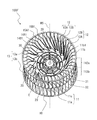
- FIG. 5 is a plan view schematically showing an impeller in the multi-blade blower according to the fifth embodiment. It is a perspective view of one side of the impeller constituting the multi-blade blower according to the sixth embodiment.
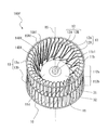
- FIG. 27 It is a perspective view of the other side of the impeller constituting the multi-blade blower according to the sixth embodiment. It is a top view of one surface side of the impeller shown in FIG. It is a top view of the other surface side of the impeller shown in FIG. 26. It is sectional drawing of the FF line position of the impeller shown in FIG. 27. It is a conceptual diagram explaining the relationship between the impeller and the motor in the multi-blade blower which concerns on Embodiment 7.
- FIG. It is a perspective view of the air conditioner which concerns on Embodiment 8. It is a figure which shows the internal structure of the air conditioner which concerns on Embodiment 8.
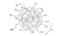
- FIG. 1 is a perspective view schematically showing the multi-blade blower 100 according to the first embodiment.
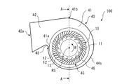
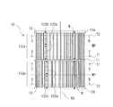
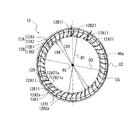
- FIG. 2 is an external view schematically showing a configuration in which the multi-blade blower 100 according to the first embodiment is viewed in parallel with the rotation axis RS.
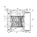
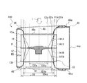
- FIG. 3 is a cross-sectional view schematically showing a cross section taken along line AA of the multi-blade blower 100 of FIG. The basic structure of the multi-blade blower 100 will be described with reference to FIGS. 1 to 3.
- the multi-blade blower 100 is a multi-blade centrifugal blower, and has an impeller 10 for generating an air flow and a scroll casing 40 for accommodating the impeller 10 inside.
- the multi-blade blower 100 is a double suction type centrifugal blower in which air is sucked from both sides of the scroll casing 40 in the axial direction of the virtual rotating shaft RS of the impeller 10.
- the scroll casing 40 houses the impeller 10 for the multi-blade blower 100 inside, and rectifies the air blown out from the impeller 10.
- the scroll casing 40 has a scroll portion 41 and a discharge portion 42.
- the scroll portion 41 forms an air passage that converts the dynamic pressure of the air flow generated by the impeller 10 into static pressure.
- the scroll portion 41 has a side wall 44a formed with a suction port 45 that covers the impeller 10 from the axial direction of the rotation shaft RS of the boss portion 11b constituting the impeller 10 and takes in air, and the impeller 10 rotates the boss portion 11b. It has a peripheral wall 44c that surrounds the impeller 10 from the radial direction of the shaft RS.
- the scroll portion 41 is located between the discharge portion 42 and the winding start portion 41a of the peripheral wall 44c to form a curved surface, and the airflow generated by the impeller 10 is sent to the discharge port 42a via the scroll portion 41. It has a guiding tongue 43.
- the radial direction of the rotating shaft RS is a direction perpendicular to the axial direction of the rotating shaft RS.
- the internal space of the scroll portion 41 composed of the peripheral wall 44c and the side wall 44a is a space in which the air blown out from the impeller 10 flows along the peripheral wall 44c.
- the side walls 44a are arranged on both sides of the impeller 10 in the axial direction of the rotating shaft RS of the impeller 10.
- a suction port 45 is formed on the side wall 44a of the scroll casing 40 so that air can flow between the impeller 10 and the outside of the scroll casing 40.
- the suction port 45 is formed in a circular shape, and the impeller 10 is arranged so that the center of the suction port 45 and the center of the boss portion 11b of the impeller 10 substantially coincide with each other.
- the shape of the suction port 45 is not limited to a circular shape, and may be another shape such as an elliptical shape.
- the scroll casing 40 of the multi-blade blower 100 is a double-suction type casing having side walls 44a having suction ports 45 formed on both sides of the main plate 11 in the axial direction of the rotation axis RS of the boss portion 11b.
- the multi-blade blower 100 has two side walls 44a in the scroll casing 40.
- the two side walls 44a are formed so as to face each other via the peripheral wall 44c. More specifically, as shown in FIG. 3, the scroll casing 40 has a first side wall 44a1 and a second side wall 44a2 as the side wall 44a.
- the first side wall 44a1 forms a first suction port 45a facing the plate surface of the main plate 11 on the side on which the first side plate 13a described later is arranged.
- the second side wall 44a2 forms a second suction port 45b facing the plate surface of the main plate 11 on the side where the second side plate 13b, which will be described later, is arranged.
- the suction port 45 described above is a general term for the first suction port 45a and the second suction port 45b.
- the suction port 45 provided on the side wall 44a is formed by a bell mouth 46. That is, the bell mouth 46 forms a suction port 45 that communicates with the space formed by the main plate 11 and the plurality of blades 12.
- the bell mouth 46 rectifies the gas sucked into the impeller 10 and causes it to flow into the suction port 10e of the impeller 10.
- the bell mouth 46 is formed so that the opening diameter gradually decreases from the outside to the inside of the scroll casing 40. Due to the configuration of the side wall 44a, the air in the vicinity of the suction port 45 flows smoothly along the bell mouth 46, and efficiently flows into the impeller 10 from the suction port 45.
- the peripheral wall 44c guides the airflow generated by the impeller 10 to the discharge port 42a along the curved wall surface.
- the peripheral wall 44c is a wall provided between the side walls 44a facing each other, and constitutes a curved surface in the rotation direction R of the impeller 10.
- the peripheral wall 44c is arranged in parallel with the axial direction of the rotation axis RS of the impeller 10, for example, and covers the impeller 10.
- the peripheral wall 44c may be inclined with respect to the axial direction of the rotating shaft RS of the impeller 10, and is not limited to the form arranged parallel to the axial direction of the rotating shaft RS.
- the peripheral wall 44c covers the impeller 10 from the radial direction of the boss portion 11b, and constitutes an inner peripheral surface facing a plurality of blades 12 described later.
- the peripheral wall 44c faces the air blowing side of the blade 12 of the impeller 10.
- the peripheral wall 44c is located at the boundary between the discharge portion 42 and the scroll portion 41 on the side away from the tongue portion 43 from the winding start portion 41a located at the boundary between the peripheral wall 44c and the tongue portion 43.
- the impeller 10 is provided along the rotation direction R of the impeller 10.
- the winding start portion 41a is an upstream end portion of the airflow generated by the rotation of the impeller 10 on the peripheral wall 44c forming the curved surface
- the winding end portion 41b is a downstream end of the airflow generated by the rotation of the impeller 10. The end of the side.
- the peripheral wall 44c is formed in a spiral shape.
- the spiral shape for example, there is a shape based on a logarithmic spiral, an Archimedes spiral, an involute curve, or the like.
- the inner peripheral surface of the peripheral wall 44c constitutes a curved surface that smoothly curves along the circumferential direction of the impeller 10 from the winding start portion 41a, which is the start of spiral winding, to the winding end portion 41b, which is the end of spiral winding. ..
- the air sent out from the impeller 10 smoothly flows in the gap between the impeller 10 and the peripheral wall 44c in the direction of the discharge portion 42. Therefore, in the scroll casing 40, the static pressure of air efficiently increases from the tongue portion 43 toward the discharge portion 42.
- the discharge unit 42 forms a discharge port 42a generated by the impeller 10 and ejecting the airflow that has passed through the scroll unit 41.
- the discharge portion 42 is composed of a hollow pipe having a rectangular cross section orthogonal to the flow direction of the air flowing along the peripheral wall 44c.
- the cross-sectional shape of the discharge portion 42 is not limited to a rectangle.
- the discharge unit 42 forms a flow path that guides the air that is sent out from the impeller 10 and flows in the gap between the peripheral wall 44c and the impeller 10 so as to be discharged to the outside of the scroll casing 40.
- the discharge portion 42 includes an extension plate 42b, a diffuser plate 42c, a first side plate portion 42d, a second side plate portion 42e, and the like.
- the extension plate 42b is formed integrally with the peripheral wall 44c so as to be smoothly continuous with the winding end 41b on the downstream side of the peripheral wall 44c.
- the diffuser plate 42c is formed integrally with the tongue portion 43 of the scroll casing 40 and faces the extension plate 42b.
- the diffuser plate 42c is formed at a predetermined angle with respect to the extending plate 42b so that the cross-sectional area of the flow path gradually expands along the air flow direction in the discharge portion 42.
- the first side plate portion 42d is integrally formed with the first side wall 44a1 of the scroll casing 40
- the second side plate portion 42e is integrally formed with the second side wall 44a2 on the opposite side of the scroll casing 40.
- the first side plate portion 42d and the second side plate portion 42e are formed between the extension plate 42b and the diffuser plate 42c.
- a flow path having a rectangular cross section is formed by the extension plate 42b, the diffuser plate 42c, the first side plate portion 42d, and the second side plate portion 42e.
- the tongue portion 43 is formed between the diffuser plate 42c of the discharge portion 42 and the winding start portion 41a of the peripheral wall 44c.
- the tongue portion 43 is formed with a predetermined radius of curvature, and the peripheral wall 44c is smoothly connected to the diffuser plate 42c via the tongue portion 43.
- the tongue portion 43 suppresses the inflow of air from the end of winding to the beginning of winding of the spiral flow path.
- the tongue portion 43 is provided in the upstream portion of the ventilation passage, and divides the air flow in the rotation direction R of the impeller 10 and the air flow in the discharge direction from the downstream portion of the ventilation passage toward the discharge port 42a. Has a role. Further, the static pressure of the air flow flowing into the discharge portion 42 increases while passing through the scroll casing 40, and the pressure becomes higher than that in the scroll casing 40. Therefore, the tongue portion 43 has a function of partitioning such a pressure difference.
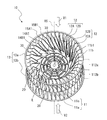
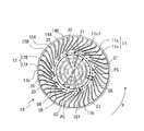
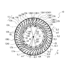
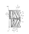
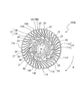
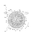
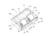
- FIG. 4 is a perspective view of the impeller 10 constituting the multi-blade blower 100 according to the first embodiment.
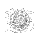
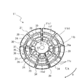
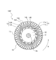
- FIG. 5 is a plan view of one surface side of the main plate 11 of FIG.
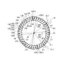
- FIG. 6 is a plan view of the other surface side of the main plate 11 of FIG.
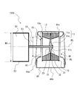
- FIG. 7 is a cross-sectional view taken along the line BB of the impeller 10 shown in FIG.
- FIG. 5 is a view of the impeller 10 seen from the viewpoint V1 indicated by the white arrow in FIG. 4, and is a plan view seen in parallel with the axial direction of the rotation axis RS.
- FIG. 6 is a view of the impeller 10 seen from the viewpoint V2 indicated by the white arrow in FIG. 4, and is a plan view seen in parallel with the axial direction of the rotation axis RS.
- the impeller 10 will be described with reference to FIGS. 4 to 7.
- the impeller 10 is a centrifugal fan.
- the impeller 10 is connected to a motor having a drive shaft (not shown).
- the impeller 10 is rotationally driven by a motor, and the centrifugal force generated by the rotation forcibly sends air outward in the radial direction.
- the impeller 10 is rotated in the rotation direction R indicated by the arrow by a motor or the like.
- the impeller 10 includes a disk-shaped main plate 11, an annular side plate 13, and a plurality of blades 12 radially arranged in the circumferential direction of the main plate 11 at the peripheral edge of the main plate 11. Has.
- the main plate 11 may have a plate shape, and may have a shape other than a disk shape, such as a polygonal shape.
- a boss portion 11b to which the drive shaft of the motor is connected is provided at the center of the main plate 11.
- a shaft hole 11b1 into which the drive shaft of the motor is inserted is formed in the boss portion 11b.
- the boss portion 11b is formed in a cylindrical shape, but the shape of the boss portion 11b is not limited to the cylindrical shape.
- the boss portion 11b may be formed in a columnar shape as long as it is formed in a columnar shape, for example, in a polygonal columnar shape.
- the main plate 11 is rotationally driven by a motor via the boss portion 11b.
- the main plate 11 is not limited to one composed of one plate-shaped member, and may be configured by integrally fixing a plurality of plate-shaped members.
- FIG. 8 is a partially enlarged view of the main plate 11 in the region shown by part E in FIG.
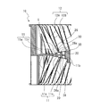
- FIG. 9 is a partially enlarged view of the impeller 10 in the region shown by the F portion of FIG.
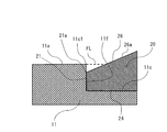
- FIG. 10 is a schematic partially enlarged view of the main plate 11 in the region shown by the G portion of FIG. The configuration of the main plate 11 will be described in more detail with reference to FIGS. 8 to 10.
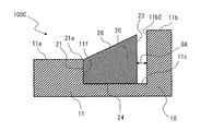
- the main plate 11 is provided in the region between the first surface portion 11a provided with the plurality of blades 12 and the boss portion 11b and the first surface portion 11a, and is provided in the axial direction of the rotation axis RS with respect to the first surface portion 11a. It has a second surface portion 11c formed in a concave shape. The first surface portion 11a is located on the side plate 13 side as compared with the second surface portion 11c.
- the first surface portion 11a is formed on the outer peripheral side of the second surface portion 11c with the rotation axis RS as the center.
- the first surface portion 11a is formed in an annular shape in a plan view seen in the axial direction of the rotation axis RS, and the second surface portion 11c is formed on the inner peripheral side of the first surface portion 11a.
- the second surface portion 11c is formed in an annular region centered on the boss portion 11b in a plan view of the rotation axis RS in the axial direction. That is, the second surface portion 11c is formed so as to be recessed in an annular shape with the boss portion 11b as the center.
- the concave shape of the second surface portion 11c is not limited to the configuration in which the boss portion 11b is formed to be recessed in an annular shape.
- the concave shape of the second surface portion 11c may be formed radially around the boss portion 11b.
- the main plate 11 may have a second surface portion 11c recessed with respect to the first surface portion 11a on the inner peripheral side of the first surface portion 11a.
- the main plate 11 has a first surface portion 11a and a second surface portion 11c on both sides of the plate surface of the main plate 11 in the axial direction of the rotation axis RS.
- the thickness of the plate constituting the second surface portion 11c is thinner than the thickness of the plate constituting the first surface portion 11a.
- the second surface portion 11c is formed so as to be recessed with respect to the first surface portion 11a. Therefore, as shown in FIG. 10, a step 11f is formed on the main plate 11 between the first surface portion 11a and the second surface portion 11c.
- the step 11f forms the outer peripheral edge 11c1 of the second surface portion 11c.
- the size of the concave outer diameter PO formed by the outer peripheral edge 11c1 of the second surface portion 11c is the inner diameter of the blade 12 composed of the inner peripheral ends 14A of each of the plurality of blades 12.
- the difference between ID1 and the concave outer diameter PO is larger than the magnitude of PS. That is, in the configuration of the main plate 11, the relationship of recess outer diameter PO> (inner diameter ID1-recess outer diameter PO) and recess outer diameter PO> difference PS is established.
- the second surface portion 11c is formed up to the vicinity of the inner diameter of the blade 12 in the radial direction centered on the rotation axis RS.
- the concave outer diameter PO is the diameter of the circle CR formed by the outer peripheral edge 11c1 of the second surface portion 11c centered on the rotation shaft RS.
- the inner diameter ID1 is the diameter of the circle C1 passing through the inner peripheral ends 14A of the plurality of first blades 12A centered on the rotation axis RS.
- the main plate 11 is provided on the second surface portion 11c and has a plurality of convex portions 20 extending in the axial direction of the rotation axis RS.
- the plurality of convex portions 20 are provided radially around the rotation axis RS, and each of the plurality of convex portions 20 extends in the radial direction about the rotation axis RS.
- the main plate 11 has a first surface portion 11a and a second surface portion 11c on both sides of the plate surface of the main plate 11, and each of the second surface portions 11c formed on both sides of the main plate 11 It has a plurality of convex portions 20.
- the main plate 11 has nine convex portions 20, but the number of convex portions 20 formed is not limited to nine.
- each of the plurality of convex portions 20 is a rib formed in a plate shape rising from the second surface portion 11c. More specifically, the convex portion 20 is formed in the shape of a square piece plate. However, the convex portion 20 may have a structure that protrudes from the second surface portion 11c, and is not limited to the plate-like structure of the square piece.
- the convex portion 20 constitutes a base portion 24 which is connected to the second surface portion 11c and is a root portion of the convex portion 20 and a tip portion in a direction protruding from the second surface portion 11c. It has a ridge portion 26 forming a ridgeline.
- the ridge line is formed by the tip portion of the convex portion 20 in the protruding direction, and when the second surface portion 11c is the bottom surface portion, the ridge line is a continuous portion of the tip portion on the opposite side of the convex portion 20 from the second surface portion 11c. Yes, it is a continuous portion of the highest portion of the convex portion 20.
- a ridge line formed by the tip portion in the protruding direction is formed in a straight line in a side view viewed from a direction perpendicular to the axial direction of the rotation axis RS.
- the ridge portion 26 is not limited to a configuration in which the ridge line is formed in a straight line when viewed from a side view from a direction perpendicular to the axial direction of the rotation axis RS.
- the convex portion 20 has a convex inner peripheral end 23 which is an end on the inner peripheral side located on the rotating shaft RS side in the radial direction centered on the rotating shaft RS, and an outer circumference on the plurality of blades 12 sides in the radial direction. It has a convex outer peripheral end 21 which is a side end.
- the inner peripheral end 23 of the convex portion constitutes an end portion on the inner peripheral side of the convex portion 20, and the outer peripheral end 21 of the convex portion constitutes an end portion on the outer peripheral side of the convex portion 20.
- each of the plurality of convex portions 20 is connected to the outer peripheral wall 11b2 of the boss portion 11b. That is, the convex inner peripheral end 23 of the convex portion 20 is connected to the boss portion 11b.
- the convex portion 20 is not limited to the configuration in which the inner peripheral end 23 of the convex portion is connected to the outer peripheral wall 11b2 of the boss portion 11b.
- a space may be formed between the inner peripheral end 23 of the convex portion 20 of the convex portion 20 and the outer peripheral wall 11b2 of the boss portion 11b in the radial direction centered on the rotation axis RS.
- Each of the plurality of convex portions 20 is connected to the step 11f. That is, the convex portion outer peripheral end 21 of the convex portion 20 is connected to the step 11f.
- the convex portion 20 is not limited to the configuration in which the outer peripheral end 21 of the convex portion is connected to the step 11f.
- a space may be formed between the outer peripheral end 21 of the convex portion 20 of the convex portion 20 and the step 11f in the radial direction centered on the rotation axis RS.
- the heights of the plurality of convex portions 20 are formed to be the same.
- the main plate 11 is not limited to those in which the heights of the plurality of convex portions 20 are formed at the same height.
- the plurality of protrusions 20 may be formed at different heights, or groups of the same height may be formed based on a certain rule.
- the height of the outer peripheral end 21 of the convex portion which is the outermost outermost portion of the convex portion 20, is It matches the height of the first surface portion 11a.
- the height of the convex portion outer peripheral end 21 which is the outermost peripheral portion of the convex portion 20 is lower than the height of the first surface portion 11a, and the upper end portion 21a of the convex portion outer peripheral end 21 is formed. It is located on the second surface portion 11c side with respect to the first surface portion 11a.
- a virtual extension surface of the first surface portion 11a is represented as an extension surface FL.
- the upper end portion 21a of the outer peripheral end 21 of the convex portion is located on the second surface portion 11c side of the extension surface FL.
- the outer peripheral end 21 of the convex portion which is the outermost peripheral portion of the convex portion 20, is formed so as not to protrude from the first surface portion 11a.
- the height of the convex inner peripheral end 23 of the convex portion 20 is equal to the height of the tip portion of the boss portion 11b or lower than the height of the tip portion of the boss portion 11b.
- the height of the tip of the boss portion 11b is higher than the height of the first surface portion 11a.
- the thickness of the plate forming the boss portion 11b is formed to be thicker than the thickness of the plate forming the first surface portion 11a.
- the height of the tip portion of the boss portion 11b is not limited to a configuration higher than the height of the first surface portion 11a, and the height of the tip portion of the boss portion 11b is equal to the height of the first surface portion 11a. It may be height.
- each of the plurality of convex portions 20 has an inclined portion 26a on the ridge portion 26.
- the inclined portion 26a is a portion of the ridge portion 26 in which the ridgeline is inclined so that the height of the rotating shaft RS in the axial direction decreases from the inner peripheral side to the outer peripheral side.
- the inclined portion 26a of the convex portion 20 is formed so that the inner peripheral end 23 side of the convex portion is higher than the outer peripheral end 21 side of the convex portion, and the ridge portion 26 constituting the inclined portion 26a is the outer peripheral end of the convex portion.
- the configuration of the inclined portion 26a is not limited to the configuration.
- the ridge line of the inclined portion 26a may be inclined so that the height of the ridge portion 26 protruding from the boss portion 11b side toward the plurality of blades 12 side becomes large.
- the inclined portion 26a of the convex portion 20 is formed so that the outer peripheral end 21 side of the convex portion is higher in height than the inner peripheral end 23 side of the convex portion, and the ridge portion 26 constituting the inclined portion 26a is convex. It is inclined so as to be separated from the main plate 11 from the inner peripheral end 23 side of the portion toward the outer peripheral end 21 side of the convex portion.
- the size of the convex outer diameter QO composed of the convex outer peripheral ends 21 of the plurality of convex portions 20 is composed of the inner peripheral ends 14A of the plurality of blades 12.
- the difference between the inner diameter ID1 of the blade 12 and the outer diameter QO of the convex portion is larger than the magnitude of QS. That is, in the configuration of the main plate 11, the relationship of convex outer diameter QO> (inner diameter ID1-convex outer diameter QO) or convex outer diameter QO> difference QS is established. Therefore, the convex portion 20 is formed up to the vicinity of the inner diameter of the blade 12 in the radial direction about the rotation axis RS.
- the convex outer diameter QO is the diameter of the circular DR passing through the convex outer peripheral ends 21 of the plurality of convex portions 20 centered on the rotation axis RS.
- the main plate 11 has recesses 34 in the front and rear of the convex portion 20 in the circumferential direction.
- the concave portion 34 is formed between the adjacent convex portions 20 in the circumferential direction.
- the recess 34 is formed by the second surface portion 11c. More specifically, the concave portion 34 is formed by a second surface portion 11c, an adjacent convex portion 20, a boss portion 11b, and a step 11f.
- the recesses 34 are formed radially with respect to the boss portion 11b.
- a plurality of recesses 34 are formed in the circumferential direction.
- the main plate 11 is provided on the second surface portion 11c and has a reinforcing portion 30 extending in the axial direction of the rotating shaft RS.
- the reinforcing portion 30 is a reinforcing rib formed in a plate shape rising from the second surface portion 11c.
- the reinforcing portion 30 is formed in an arc shape in a plan view in a direction parallel to the axial direction of the rotating shaft RS, and connects each of the plurality of convex portions 20 in the circumferential direction. Therefore, the reinforcing portion 30 is formed in an annular shape in a plan view viewed in a direction parallel to the axial direction of the rotating shaft RS.
- the reinforcing portion 30 is connected to the convex portion 20.
- the reinforcing portion 30 constitutes a wall having a height equal to the height of the wall of the convex portion 20 at a position where it is connected to the convex portion 20.
- a plurality of reinforcing portions 30 are provided in the radial direction centered on the rotation axis RS.
- the main plate 11 is a reinforcing portion located on the inner peripheral side of the reinforcing portion 30 located on the outer peripheral side in the radial direction centered on the rotation axis RS. 30 is formed so that the height of the wall is higher. As shown in FIG. 8, the main plate 11 has reinforcing portions 30 forming two circles, but the number of reinforcing portions 30 formed is not limited to two.
- the main plate 11 has a concave portion 35 formed in a concave shape by a convex portion 20, a reinforcing portion 30, and a second surface portion 11c.
- the main plate 11 forms a concave portion 36 formed in a concave shape by the convex portion 20, the reinforcing portion 30, the step 11f, and the second surface portion 11c.
- the main plate 11 forms a concave portion 37 formed in a concave shape by the convex portion 20, the reinforcing portion 30, the outer peripheral wall 11b2 of the boss portion 11b, and the second surface portion 11c.
- the plurality of blades 12 have one end connected to the main plate 11 and the other end connected to the side plate 13, and are arranged in the circumferential direction centered on the virtual rotation axis RS of the main plate 11. There is.
- Each of the plurality of blades 12 is arranged between the main plate 11 and the side plate 13.
- the plurality of blades 12 are provided on both sides of the main plate 11 in the axial direction of the rotation shaft RS of the boss portion 11b.
- the blades 12 are arranged at a certain distance from each other on the peripheral edge of the main plate 11. The detailed configuration of each blade 12 will be described later.
- the impeller 10 has an annular side plate 13 attached to an end portion of the boss portion 11b opposite to the main plate 11 of the plurality of blades 12 in the axial direction of the rotation shaft RS.
- the side plate 13 is arranged in the impeller 10 so as to face the main plate 11.
- the side plate 13 maintains the positional relationship of the tips of the respective blades 12 by connecting the plurality of blades 12, and reinforces the plurality of blades 12.
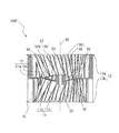
- FIG. 11 is a side view of the impeller 10 of FIG.
- the impeller 10 has a first wing portion 112a and a second wing portion 112b, as shown in FIGS. 4 and 11.
- the first wing portion 112a and the second wing portion 112b are composed of a plurality of blades 12 and side plates 13. More specifically, the first wing portion 112a is formed by an annular first side plate 13a arranged to face the main plate 11 and a plurality of blades 12 arranged between the main plate 11 and the first side plate 13a. It is configured.
- the second wing portion 112b includes an annular second side plate 13b arranged opposite to the main plate 11 on the side opposite to the side where the first side plate 13a is arranged with respect to the main plate 11, and the main plate 11 and the second side plate. It is composed of a plurality of blades 12 arranged between 13b and 13b.
- the side plate 13 is a general term for the first side plate 13a and the second side plate 13b, and the impeller 10 has the first side plate 13a on one side with respect to the main plate 11 in the axial direction of the rotating shaft RS, and the other. It has a second side plate 13b on the side of.
- the first wing portion 112a is arranged on one plate surface side of the main plate 11, and the second wing portion 112b is arranged on the other plate surface side of the main plate 11. That is, the plurality of blades 12 are provided on both sides of the main plate 11 in the axial direction of the rotation axis RS, and the first blade portion 112a and the second blade portion 112b are provided back to back via the main plate 11. ing.
- the first wing portion 112a is arranged on the left side with respect to the main plate 11, and the second wing portion 112b is arranged on the right side with respect to the main plate 11.
- first wing portion 112a and the second wing portion 112b need only be provided back to back via the main plate 11, and the first wing portion 112a is arranged on the right side of the main plate 11 and is provided on the main plate 11.
- the second wing portion 112b may be arranged on the left side.
- the blade 12 is described as a general term for the blade 12 constituting the first blade portion 112a and the blade 12 constituting the second blade portion 112b.
- the impeller 10 is formed in a tubular shape by a plurality of blades 12 arranged on the main plate 11. Then, the impeller 10 allows gas to flow into the space surrounded by the main plate 11 and the plurality of blades 12 on the side plate 13 side opposite to the main plate 11 in the axial direction of the rotation shaft RS of the boss portion 11b.
- the suction port 10e is formed.
- blades 12 and side plates 13 are arranged on both sides of the plate surface forming the main plate 11, and suction ports 10e are formed on both sides of the plate surface forming the main plate 11.
- the impeller 10 is rotationally driven around the rotary shaft RS by being driven by a motor (not shown). As the impeller 10 rotates, the gas outside the multi-blade blower 100 passes through the suction port 45 formed in the scroll casing 40 shown in FIG. 1 and the suction port 10e of the impeller 10, and the main plate 11 and a plurality of them. It is sucked into the space surrounded by the wings 12. Then, as the impeller 10 rotates, the air sucked into the space surrounded by the main plate 11 and the plurality of blades 12 passes through the space between the blades 12 and the adjacent blades 12, and the diameter of the impeller 10 is increased. It is sent out of the direction.
- FIG. 12 is a schematic view showing the blade 12 in the CC line cross section of the impeller 10 of FIG.
- FIG. 13 is a schematic view showing the blade 12 in the DD line cross section of the impeller 10 of FIG.
- the intermediate position MP of the impeller 10 shown in FIG. 11 indicates an intermediate position in the axial direction of the rotation axis RS in the plurality of blades 12 constituting the first blade portion 112a.
- each of the plurality of blades 12 has a first region located closer to the main plate 11 than the intermediate position MP in the axial direction of the rotation axis RS, and a second region located closer to the side plate 13 than the first region.
- the CC line cross section shown in FIG. 11 is a cross section of a plurality of blades 12 on the main plate 11 side of the impeller 10, that is, the main plate side blade region 122a, which is the first region.
- the cross section of the blade 12 on the main plate 11 side is the first plane 71 perpendicular to the rotation axis RS, and the portion of the impeller 10 near the main plate 11 is cut off, which is the first cross section of the impeller 10.
- the portion of the impeller 10 closer to the main plate 11 is, for example, a portion closer to the main plate 11 than the intermediate position of the main plate side blade region 122a in the axial direction of the rotating shaft RS, or a blade in the axial direction of the rotating shaft RS. This is a portion where the end portion of the main plate 12 on the 11 side is located.
- the DD line cross section shown in FIG. 11 is a cross section of a plurality of blades 12 on the side plate 13 side of the impeller 10, that is, the side plate side blade region 122b which is the second region.
- the cross section of the blade 12 on the side plate 13 side is a second plane 72 perpendicular to the rotation axis RS, and the portion of the impeller 10 near the side plate 13 is cut off, which is the second cross section of the impeller 10.
- the portion of the impeller 10 closer to the side plate 13 is, for example, a portion closer to the side plate 13 than the intermediate position of the side plate side blade region 122b in the axial direction of the rotating shaft RS, or a blade in the axial direction of the rotating shaft RS. This is a portion where the end portion of the side plate 12 on the 13 side is located.
- the basic configuration of the blade 12 in the second blade portion 112b is the same as the basic configuration of the blade 12 in the first blade portion 112a. That is, the intermediate position MP of the impeller 10 shown in FIG. 5 indicates an intermediate position in the axial direction of the rotation axis RS in the plurality of blades 12 constituting the second blade portion 112b.
- the region from the intermediate position MP in the axial direction of the rotating shaft RS to the main plate 11 is defined as the main plate side blade region 122a, which is the first region of the impeller 10.
- the region from the intermediate position MP in the axial direction of the rotating shaft RS to the end portion on the second side plate 13b side is the side plate side which is the second region of the impeller 10.
- the blade region 122b is defined in the plurality of blades 12 constituting the second blade portion 112b.
- first wing portion 112a and the basic configuration of the second wing portion 112b are the same, but the configuration of the impeller 10 is limited to this configuration. Instead, the first wing portion 112a and the second wing portion 112b may have different configurations.
- the configuration of the blade 12 described below may be possessed by both the first blade portion 112a and the second blade portion 112b, or may be possessed by either one.
- the plurality of blades 12 have a plurality of first blades 12A and a plurality of second blades 12B.
- the first blade 12A and one or a plurality of second blades 12B are alternately arranged in the circumferential direction of the impeller 10.
- the impeller 10 has two second blades 12B arranged between the first blade 12A and the first blade 12A arranged adjacent to each other in the rotation direction R.
- the number of the second blades 12B arranged between the first blade 12A and the first blade 12A arranged adjacent to each other in the rotation direction R is not limited to two, and one or three or more. It may be. That is, at least one second blade 12B of the plurality of second blades 12B is arranged between the two first blades 12A adjacent to each other in the circumferential direction among the plurality of first blades 12A.
- the first blade 12A has an inner peripheral end 14A and an outer peripheral end 15A in the first cross section of the impeller 10 cut by the first plane 71 perpendicular to the rotation axis RS.
- the inner peripheral end 14A is located on the rotating shaft RS side in the radial direction centered on the rotating shaft RS, and the outer peripheral end 15A is located on the outer peripheral side of the inner peripheral end 14A in the radial direction.
- the inner peripheral end 14A is arranged in front of the outer peripheral end 15A in the rotation direction R of the impeller 10.
- the inner peripheral end 14A is the leading edge 14A1 of the first blade 12A
- the outer peripheral end 15A is the trailing edge 15A1 of the first blade 12A.
- 14 first blades 12A are arranged on the impeller 10, but the number of the first blades 12A is not limited to 14, and may be less than 14. Well, it may be more than 14.
- the second blade 12B has an inner peripheral end 14B and an outer peripheral end 15B in the first cross section of the impeller 10 cut by the first plane 71 perpendicular to the rotation axis RS.
- the inner peripheral end 14B is located on the rotating shaft RS side in the radial direction centered on the rotating shaft RS, and the outer peripheral end 15B is located on the outer peripheral side of the inner peripheral end 14B in the radial direction.
- the inner peripheral end 14B is arranged in front of the outer peripheral end 15B in the rotation direction R of the impeller 10.
- the inner peripheral end 14B is the leading edge 14B1 of the second blade 12B
- the outer peripheral end 15B is the trailing edge 15B1 of the second blade 12B.
- 28 second blades 12B are arranged on the impeller 10, but the number of the second blades 12B is not limited to 28, and may be less than 28. Well, it may be more than 28 sheets.
- the wingspan of the first blade 12A is the same as that of the second blade 12B. It is equal to the wingspan.
- the wingspan of the first blade 12A is longer than the wingspan of the second blade 12B in the portion closer to the main plate 11 than the intermediate position MP in the direction along the rotation axis RS. And the closer it is to the main plate 11, the longer it becomes.
- the wingspan of the first blade 12A is longer than the wingspan of the second blade 12B at least in a part of the direction along the rotation axis RS.
- the blade length used here is the length of the first blade 12A in the radial direction of the impeller 10 and the length of the second blade 12B in the radial direction of the impeller 10.
- the diameter of the circle C1 passing through the inner peripheral ends 14A of the plurality of first blades 12A centered on the rotation axis RS That is, the inner diameter of the first blade 12A is defined as the inner diameter ID1.
- the diameter of the circle C3 passing through the outer peripheral ends 15A of the plurality of first blades 12A centered on the rotation axis RS, that is, the outer diameter of the first blade 12A is defined as the outer diameter OD1.
- the ratio of the inner diameter of the first blade 12A to the outer diameter of the first blade 12A is 0.7 or less. That is, the plurality of first blades 12A has an inner diameter ID1 composed of the inner peripheral ends 14A of the plurality of first blades 12A and an outer diameter OD1 composed of the outer peripheral ends 15A of the plurality of first blades 12A. The ratio with is 0.7 or less.
- the blade length in the cross section perpendicular to the rotation axis is shorter than the blade width dimension in the rotation axis direction.
- the maximum blade length of the first blade 12A that is, the blade length at the end of the first blade 12A near the main plate 11, is the width dimension W of the first blade 12A in the rotation axis direction (see FIG. 11). Is shorter than.
- the diameter of the circle C2 passing through the inner peripheral ends 14B of the plurality of second blades 12B centered on the rotation axis RS, that is, the inner diameter of the second blade 12B is defined as the inner diameter ID2 larger than the inner diameter ID1.
- Blade length L2a (outer diameter OD2-inner diameter ID2) / 2).
- the wingspan L2a of the second blade 12B in the first cross section is shorter than the wingspan L1a of the first blade 12A in the same cross section (wing length L2a ⁇ wing length L1a).
- the ratio of the inner diameter of the second blade 12B to the outer diameter of the second blade 12B is 0.7 or less. That is, the plurality of second blades 12B have an inner diameter ID2 composed of the inner peripheral ends 14B of each of the plurality of second blades 12B and an outer diameter OD2 composed of the outer peripheral ends 15B of the plurality of second blades 12B.
- the ratio with is 0.7 or less.
- the diameter of the circle C7 passing through the inner peripheral end 14A of the first blade 12A centered on the rotation axis RS is defined.
- Inner diameter ID3 is larger than the inner diameter ID1 of the first cross section (inner diameter ID3> inner diameter ID1).
- the diameter of the circle C8 passing through the outer peripheral end 15A of the first blade 12A centered on the rotation axis RS is defined as the outer diameter OD3.
- the diameter of the circle C7 passing through the inner peripheral end 14B of the second blade 12B centered on the rotation axis RS is defined as the inner diameter ID4.
- the diameter of the circle C8 passing through the outer peripheral end 15B of the second blade 12B centered on the rotation axis RS is defined as the outer diameter OD4.
- Blade length L2b (outer diameter OD4-inner diameter ID4) / 2).
- the inner diameter of the plurality of blades 12 is composed of the inner peripheral ends of the plurality of blades 12. That is, the blade inner diameter of the plurality of blades 12 is composed of the leading edges 14A1 of the plurality of blades 12. Further, the blade outer diameter of the plurality of blades 12 is composed of the outer peripheral ends of the plurality of blades 12. That is, the blade outer diameter of the plurality of blades 12 is composed of the trailing edge 15A1 and the trailing edge 15B1 of the plurality of blades 12.
- the first blade 12A has a relationship of blade length L1a> blade length L1b in comparison between the first cross section shown in FIG. 12 and the second cross section shown in FIG. That is, each of the plurality of blades 12 is formed so that the blade length in the first region is longer than the blade length in the second region. More specifically, the first blade 12A is formed so that the blade length decreases from the main plate 11 side to the side plate 13 side in the axial direction of the rotation axis RS.
- the second blade 12B has a relationship of blade length L2a> blade length L2b in comparison between the first cross section shown in FIG. 12 and the second cross section shown in FIG. That is, the second blade 12B is formed so that the blade length decreases from the main plate 11 side to the side plate 13 side in the axial direction of the rotation shaft RS.
- the leading edges of the first blade 12A and the second blade 12B are inclined so that the inner diameter of the blade increases from the main plate 11 side to the side plate 13 side. That is, the plurality of blades 12 are formed so that the inner diameter of the blades increases from the main plate 11 side to the side plate 13 side, and the inner peripheral ends 14A constituting the leading edge 14A1 are inclined so as to be separated from the rotation axis RS.
- the inclined portion 141A is formed.
- the plurality of blades 12 are formed so that the inner diameter of the blades increases from the main plate 11 side to the side plate 13 side so that the inner peripheral end 14B constituting the leading edge 14B1 is separated from the rotation axis RS. It forms an inclined inclined portion 141B.
- the first blade 12A includes a first sirocco blade portion 12A1 including an outer peripheral end 15A and configured as a forward blade, and a first blade 12A including an inner peripheral end 14A and configured as a rear blade. It has one turbo blade portion 12A2.
- the first sirocco blade portion 12A1 constitutes the outer peripheral side of the first blade 12A
- the first turbo blade portion 12A2 constitutes the inner peripheral side of the first blade 12A. That is, the first blade 12A is configured in the order of the first turbo blade portion 12A2 and the first sirocco blade portion 12A1 from the rotation axis RS toward the outer peripheral side in the radial direction of the impeller 10.
- the first turbo blade portion 12A2 and the first sirocco blade portion 12A1 are integrally formed.
- the first turbo blade portion 12A2 constitutes the leading edge 14A1 of the first blade 12A
- the first sirocco blade portion 12A1 constitutes the trailing edge 15A1 of the first blade 12A.
- the first turbo blade portion 12A2 extends linearly from the inner peripheral end 14A constituting the leading edge 14A1 toward the outer peripheral side in the radial direction of the impeller 10.
- the region constituting the first sirocco blade portion 12A1 of the first blade 12A is defined as the first sirocco region 12A11, and the region constituting the first turbo blade portion 12A2 of the first blade 12A is the first. It is defined as 1 turbo region 12A21.
- the first turbo region 12A21 is larger than the first sirocco region 12A11 in the radial direction of the impeller 10.
- the impeller 10 has a first sirocco region 12A11 ⁇ first turbo in the radial direction of the impeller 10 in any region of the main plate side blade region 122a which is the first region and the side plate side blade region 122b which is the second region. It has a relationship of regions 12A21.
- the impeller 10 and the first blade 12A are the first turbo blades in the radial direction of the impeller 10 in any region of the main plate side blade region 122a which is the first region and the side plate side blade region 122b which is the second region.
- the proportion of the portion 12A2 is larger than the proportion of the first sirocco wing portion 12A1.
- the second blade 12B includes the second sirocco blade portion 12B1 including the outer peripheral end 15B and is configured as a forward blade, and the inner peripheral end 14B as a rear blade. It has a second turbo blade portion 12B2 that has been made.
- the second sirocco blade portion 12B1 constitutes the outer peripheral side of the second blade 12B
- the second turbo blade portion 12B2 constitutes the inner peripheral side of the second blade 12B. That is, the second blade 12B is configured in the order of the second turbo blade portion 12B2 and the second sirocco blade portion 12B1 from the rotation axis RS toward the outer peripheral side in the radial direction of the impeller 10.
- the second turbo blade portion 12B2 and the second sirocco blade portion 12B1 are integrally formed.
- the second turbo blade portion 12B2 constitutes the leading edge 14B1 of the second blade 12B
- the second sirocco blade portion 12B1 constitutes the trailing edge 15B1 of the second blade 12B.
- the second turbo blade portion 12B2 extends linearly from the inner peripheral end 14B constituting the leading edge 14B1 toward the outer peripheral side in the radial direction of the impeller 10.
- the region constituting the second sirocco blade portion 12B1 of the second blade 12B is defined as the second sirocco region 12B11, and the region constituting the second turbo blade portion 12B2 of the second blade 12B is the first.
- 2 Turbo region 12B21 is defined. In the second blade 12B, the second turbo region 12B21 is larger than the second sirocco region 12B11 in the radial direction of the impeller 10.
- the impeller 10 has a second sirocco region 12B11 ⁇ second turbo in the radial direction of the impeller 10 in any region of the main plate side blade region 122a which is the first region and the side plate side blade region 122b which is the second region. It has a relationship of region 12B21.
- the impeller 10 and the second blade 12B have a second turbo blade in the radial direction of the impeller 10 in any region of the main plate side blade region 122a which is the first region and the side plate side blade region 122b which is the second region.
- the proportion of the portion 12B2 is larger than the proportion of the second sirocco wing portion 12B1.
- the plurality of blades 12 have a turbo blade region larger than a sirocco blade region in the radial direction of the impeller 10 in any region of the main plate side blade region 122a and the side plate side blade region 122b. .. That is, in the plurality of blades 12, the ratio of the turbo blades is larger than the ratio of the sirocco blades in the radial direction of the impeller 10 in both the main plate side blade region 122a and the side plate side blade region 122b, and the sirocco It has a relationship of region ⁇ turbo region. In other words, in each of the plurality of blades 12, the ratio of the turbo blade portion in the radial direction is larger than the ratio of the sirocco blade portion in the first region and the second region.
- the ratio of the turbo blades is larger than the ratio of the sirocco blades in the radial direction of the impeller 10 of the plurality of blades 12, and the sirocco region ⁇ It is not limited to those having a turbo region relationship.
- the ratio of the turbo blade portion in the radial direction may be equal to the ratio of the sirocco blade portion or smaller than the ratio of the sirocco blade portion in the first region and the second region.
- the outlet angle of the first sirocco blade portion 12A1 of the first blade 12A in the first cross section is defined as the exit angle ⁇ 1.
- the exit angle ⁇ 1 is the angle formed by the tangent line TL1 of the circle and the center line CL1 of the first sirocco wing portion 12A1 at the outer peripheral end 15A at the intersection of the arc of the circle C3 centered on the rotation axis RS and the outer peripheral end 15A. Define.
- This exit angle ⁇ 1 is an angle larger than 90 degrees.
- the outlet angle of the second sirocco blade portion 12B1 of the second blade 12B in the same cross section is defined as the exit angle ⁇ 2.
- the exit angle ⁇ 2 is the angle formed by the tangent line TL2 of the circle and the center line CL2 of the second sirocco wing portion 12B1 at the outer peripheral end 15B at the intersection of the arc of the circle C3 centered on the rotation axis RS and the outer peripheral end 15B. Define.
- the exit angle ⁇ 2 is an angle larger than 90 degrees.
- the first sirocco wing portion 12A1 and the second sirocco wing portion 12B1 are formed in an arc shape so as to be convex in the direction opposite to the rotation direction R when viewed in parallel with the rotation axis RS.
- the outlet angle ⁇ 1 of the first sirocco wing portion 12A1 and the exit angle ⁇ 2 of the second sirocco wing portion 12B1 are equal even in the second cross section. That is, the plurality of blades 12 have sirocco blades forming forward blades formed at an exit angle larger than 90 degrees from the main plate 11 to the side plates 13.
- the outlet angle of the first turbo blade portion 12A2 of the first blade 12A in the first cross section is defined as the exit angle ⁇ 1.
- the exit angle ⁇ 1 is defined as the angle formed by the tangent line TL3 of the circle and the center line CL3 of the first turbo blade portion 12A2 at the intersection of the arc of the circle C4 centered on the rotation axis RS and the first turbo blade portion 12A2. do.
- This exit angle ⁇ 1 is an angle smaller than 90 degrees.
- the outlet angle of the second turbo blade portion 12B2 of the second blade 12B in the same cross section is defined as the outlet angle ⁇ 2.
- the exit angle ⁇ 2 is defined as the angle formed by the tangent line TL4 of the circle and the center line CL4 of the second turbo blade portion 12B2 at the intersection of the arc of the circle C4 centered on the rotation axis RS and the second turbo blade portion 12B2. do.
- the exit angle ⁇ 2 is an angle smaller than 90 degrees.
- the outlet angle ⁇ 1 of the first turbo blade portion 12A2 and the outlet angle ⁇ 2 of the second turbo blade portion 12B2 are equal even in the second cross section. Further, the exit angle ⁇ 1 and the exit angle ⁇ 2 are angles smaller than 90 degrees.
- the first blade 12A has a first radial blade portion 12A3 as a connecting portion between the first turbo blade portion 12A2 and the first sirocco blade portion 12A1.
- the first radial blade portion 12A3 is a portion configured as a radial blade extending linearly in the radial direction of the impeller 10.
- the second blade 12B has a second radial blade portion 12B3 as a connecting portion between the second turbo blade portion 12B2 and the second sirocco blade portion 12B1.
- the second radial blade portion 12B3 is a portion configured as a radial blade extending linearly in the radial direction of the impeller 10.
- the blade angles of the first radial blade portion 12A3 and the second radial blade portion 12B3 are 90 degrees. More specifically, the angle formed by the tangent line at the intersection of the center line of the first radial wing portion 12A3 and the circle C5 centered on the rotation axis RS and the center line of the first radial wing portion 12A3 is 90 degrees. Further, the angle formed by the tangent line at the intersection of the center line of the second radial wing portion 12B3 and the circle C5 centered on the rotation axis RS and the center line of the second radial wing portion 12B3 is 90 degrees.
- the space between the blades in the turbo blade portion composed of the first turbo blade portion 12A2 and the second turbo blade portion 12B2 extends from the inner peripheral side to the outer peripheral side.
- the space between the blades in the sirocco blade portion composed of the first sirocco blade portion 12A1 and the second sirocco blade portion 12B1 is wider than the space between the blades of the turbo blade portion, and extends from the inner peripheral side to the outer peripheral side.
- the space between the blades between the first turbo blade 12A2 and the second turbo blade 12B2, or the space between the adjacent second turbo blades 12B2 extends from the inner peripheral side to the outer peripheral side. Further, the distance between the blades of the first sirocco blade portion 12A1 and the second sirocco blade portion 12B1 or the distance between the adjacent second sirocco blade portions 12B1 is wider and the inner circumference than the distance between the blades of the turbo blade portion. It extends from the side to the outer circumference.
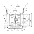
- FIG. 14 is a schematic view showing the relationship between the impeller 10 and the bell mouth 46 in the AA line cross section of the multi-blade blower 100 of FIG.
- FIG. 15 is a schematic view showing the relationship between the blade 12 and the bell mouth 46 when viewed in parallel with the rotation axis RS in the second cross section of the impeller 10 of FIG.
- the blade outer diameter OD composed of the outer peripheral ends of the plurality of blades 12 is larger than the inner diameter BI of the bell mouth 46 constituting the scroll casing 40.
- the first turbo region 12A21 is larger than the first sirocco region 12A11 in the radial direction with respect to the rotating shaft RS. That is, in the impeller 10 and the first blade 12A, the ratio of the first turbo blade portion 12A2 is larger than the ratio of the first sirocco blade portion 12A1 in the radial direction with respect to the rotation axis RS, and the ratio of the first sirocco blade portion 12A1 ⁇ 1st It has a relationship of turbo blade portion 12A2.
- the relationship between the ratio of the first sirocco blade portion 12A1 and the first turbo blade portion 12A2 in the radial direction of the rotating shaft RS is either the main plate side blade region 122a which is the first region or the side plate side blade region 122b which is the second region. It also holds in the area of.
- the ratio of the first turbo blade portion 12A2 is larger than the ratio of the first sirocco blade portion 12A1 in the radial direction with respect to the rotation axis RS, and the ratio of the first sirocco blade portion 12A1 ⁇ 1st It is not limited to those having a relationship of the turbo blade portion 12A2.
- the ratio of the first turbo blade portion 12A2 is equal to the ratio of the first sirocco blade portion 12A1 or higher than the ratio of the first sirocco blade portion 12A1 in the radial direction with respect to the rotation axis RS. It may be formed to be small.
- the region of the plurality of blades 12 on the outer peripheral side of the inner diameter BI of the bell mouth 46 in the radial direction with respect to the rotating shaft RS is defined as the outer peripheral side region 12R.
- the ratio of the first turbo blade portion 12A2 is larger than the ratio of the first sirocco blade portion 12A1 even in the outer peripheral side region 12R. That is, when viewed in parallel with the rotating shaft RS, in the outer peripheral side region 12R of the impeller 10 located on the outer peripheral side of the inner diameter BI of the bell mouth 46, the first turbo region 12A21a is the first in the radial direction with respect to the rotating shaft RS. It is larger than the sirocco region 12A11.
- the first turbo region 12A21a is a region of the first turbo region 12A21 located on the outer peripheral side of the inner diameter BI of the bell mouth 46 when viewed in parallel with the rotation axis RS.
- the ratio of the first turbo blade portion 12A2a to the outer peripheral side region 12R of the impeller 10 is the first sirocco blade. It is desirable that it is larger than the ratio of the portion 12A1.
- the relationship between the ratio of the first sirocco blade portion 12A1 and the first turbo blade portion 12A2a in the outer peripheral side region 12R is any region of the main plate side blade region 122a which is the first region and the side plate side blade region 122b which is the second region. It also holds in.
- the second turbo region 12B21 is larger than the second sirocco region 12B11 in the radial direction with respect to the rotating shaft RS. That is, in the impeller 10 and the second blade 12B, the ratio of the second turbo blade portion 12B2 is larger than the ratio of the second sirocco blade portion 12B1 in the radial direction with respect to the rotation axis RS, and the second sirocco blade portion 12B1 ⁇ second It has a relationship of turbo blade portion 12B2.
- the relationship between the ratio of the second sirocco blade portion 12B1 and the second turbo blade portion 12B2 in the radial direction of the rotating shaft RS is either the main plate side blade region 122a which is the first region or the side plate side blade region 122b which is the second region. It also holds in the area of.
- the ratio of the second turbo blade portion 12B2 is larger than the ratio of the second sirocco blade portion 12B1 in the radial direction with respect to the rotation axis RS, and the second sirocco blade portion 12B1 ⁇ second It is not limited to those having a relationship of the turbo blade portion 12B2.
- the ratio of the second turbo blade portion 12B2 is equal to the ratio of the second sirocco blade portion 12B1 or higher than the ratio of the second sirocco blade portion 12B1 in the radial direction with respect to the rotation axis RS. It may be formed small.
- the ratio of the second turbo blade portion 12B2 is larger than the ratio of the second sirocco blade portion 12B1 even in the outer peripheral side region 12R. That is, when viewed in parallel with the rotating shaft RS, in the outer peripheral side region 12R of the impeller 10 located on the outer peripheral side of the inner diameter BI of the bell mouth 46, the second turbo region 12B21a is the second in the radial direction with respect to the rotating shaft RS. It is larger than the sirocco region 12B11.
- the second turbo region 12B21a is a region of the second turbo region 12B21 located on the outer peripheral side of the inner diameter BI of the bell mouth 46 when viewed in parallel with the rotation axis RS.
- the ratio of the second turbo blade portion 12B2a to the outer peripheral side region 12R of the impeller 10 is the second sirocco blade. It is desirable that it is larger than the ratio of the portion 12B1.
- the relationship between the ratio of the second sirocco blade portion 12B1 and the second turbo blade portion 12B2a in the outer peripheral side region 12R is any region of the main plate side blade region 122a which is the first region and the side plate side blade region 122b which is the second region. It also holds in.
- FIG. 16 is a schematic view showing the relationship between the impeller 10 and the bell mouth 46 in the AA line cross section of the multi-blade blower 100 of FIG.
- FIG. 17 is a schematic view showing the relationship between the blade 12 and the bell mouth 46 when viewed in parallel with the rotation axis RS in the impeller 10 of FIG.
- the white arrow L shown in FIG. 16 indicates the direction when the impeller 10 is viewed in parallel with the rotation axis RS.
- the circle passing through the end 14A is defined as the circle C1a.
- the diameter of the circle C1a that is, the inner diameter of the first blade 12A at the connection position between the first blade 12A and the main plate 11, is defined as the inner diameter ID1a.
- a circle passing through the inner peripheral ends 14B of the plurality of second blades 12B centered on the rotation axis RS is a circle C2a.
- the diameter of the circle C2a that is, the inner diameter of the second blade 12B at the connection position between the first blade 12A and the main plate 11, is defined as the inner diameter ID2a.
- the inner diameter ID2a is larger than the inner diameter ID1a (inner diameter ID2a> inner diameter ID1a).
- the outer diameter of the blade 12 is defined as the blade outer diameter OD.
- a circle passing through the inner peripheral ends 14A of the plurality of first blades 12A centered on the rotation axis RS is a circle C7a. Is defined as. Then, the diameter of the circle C7a, that is, the inner diameter of the first blade 12A at the connection position between the first blade 12A and the side plate 13, is defined as the inner diameter ID3a.
- the circle passing through the inner peripheral ends 14B of the plurality of second blades 12B centered on the rotation axis RS is a circle C7a. It becomes. Then, the diameter of the circle C7a, that is, the inner diameter of the second blade 12B at the connection position between the second blade 12B and the side plate 13, is defined as the inner diameter ID4a.
- the positions of the inner diameter BI of the bell mouth 46 are the inner diameter ID1a on the main plate 11 side of the first blade 12A and the inner diameter ID3a on the side plate 13 side. It is located in the region of the first turbo blade portion 12A2 and the second turbo blade portion 12B2 between and. More specifically, the inner diameter BI of the bell mouth 46 is larger than the inner diameter ID1a on the main plate 11 side of the first blade 12A and smaller than the inner diameter ID3a on the side plate 13 side.
- the inner diameter BI of the bell mouth 46 is formed to be larger than the inner diameter of the blades on the main plate 11 side of the plurality of blades 12 and smaller than the inner diameter of the blades on the side plate 13 side.
- the opening 46a forming the inner diameter BI of the bell mouth 46 is the first turbo wing portion 12A2 and the second turbo wing portion between the circle C1a and the circle C7a when viewed in parallel with the rotation axis RS. It is located in the area of 12B2.
- the positions of the inner diameter BI of the bell mouth 46 when viewed in parallel with the rotation axis RS are the inner diameter ID2a on the main plate 11 side of the second blade 12B and the inner diameter on the side plate 13 side. It is located in the region of the first turbo blade portion 12A2 and the second turbo blade portion 12B2 between the ID 4a and the first turbo blade portion 12A2. More specifically, the inner diameter BI of the bell mouth 46 is larger than the inner diameter ID2a on the main plate 11 side of the second blade 12B and smaller than the inner diameter ID4a on the side plate 13 side.
- the inner diameter BI of the bell mouth 46 is formed to be larger than the inner diameter of the blades on the main plate 11 side of the plurality of blades 12 and smaller than the inner diameter of the blades on the side plate 13 side. More specifically, the inner diameter BI of the bell mouth 46 is larger than the inner diameter of the blades composed of the inner peripheral ends of the plurality of blades 12 in the first region, and the inner circumferences of the plurality of blades 12 in the second region are each larger. It is formed smaller than the inner diameter of the blade composed of the ends.
- the opening 46a forming the inner diameter BI of the bell mouth 46 is the first turbo wing portion 12A2 and the second turbo wing portion between the circle C2a and the circle C7a when viewed in parallel with the rotation axis RS. It is located in the area of 12B2.
- the radial lengths of the first sirocco blade portion 12A1 and the second sirocco blade portion 12B1 are defined as the distance SL.
- the closest distance between the plurality of blades 12 of the impeller 10 and the peripheral wall 44c of the scroll casing 40 is defined as the distance MS.
- the distance MS is larger than twice the distance SL (distance MS> distance SL ⁇ 2).
- the distance MS is shown in the multi-blade blower 100 having a cross section taken along the line AA in FIG. 16, but the distance MS is the closest distance to the peripheral wall 44c of the scroll casing 40, and is not necessarily the line AA. It is not represented on the cross section.
- the main plate 11 is provided in the region between the first surface portion 11a provided with the plurality of blades 12 and the boss portion 11b and the first surface portion 11a, and is provided in the axial direction of the rotation axis RS with respect to the first surface portion 11a. It has a second surface portion 11c formed in a concave shape. Further, the main plate 11 is provided on the second surface portion 11c and has a plurality of convex portions 20 extending in the axial direction of the rotation axis RS.
- the convex portion 20 When the impeller 10 is rotating, the convex portion 20 induces an air flow by generating a negative pressure on the surface opposite to the rotation direction R of the impeller 10, and sucks air into the impeller 10. The amount can be increased. Further, the impeller 10 has a second surface portion 11c formed in a concave shape in the axial direction of the rotation shaft RS with respect to the first surface portion 11a provided with the plurality of blades 12, and the convex portion 20 is the second surface portion. It is formed in 11c. Therefore, the airflow generated by the convex portion 20 is suppressed from flowing from the second surface portion 11c to the first surface portion 11a.
- the impeller 10 can improve the ventilation efficiency as compared with the case where the impeller 10 does not have the convex portion 20 and the second surface portion 11c.
- the impeller 10 can suppress noise caused by turbulence of the air flow.
- the second surface portion 11c is formed in an annular shape with the boss portion 11b as the center. Therefore, the airflow generated by the convex portion 20 is suppressed from flowing from the second surface portion 11c to the first surface portion 11a. Then, in the airflow generated by the convex portion 20, the force of the wind toward the outer peripheral side is suppressed by the step 11f between the first surface portion 11a and the second surface portion 11c, and the impeller 10 is on the inner peripheral side of the blade 12. The airflow is not disturbed. Therefore, the impeller 10 can improve the ventilation efficiency.
- the impeller 10 since the second surface portion 11c is formed in an annular shape with the boss portion 11b as the center, the impeller 10 has the force of the wind toward the outer peripheral side at any position in the circumferential direction centering on the boss portion 11b. Can be suppressed. Further, since the second surface portion 11c is formed in an annular shape around the boss portion 11b, the impeller 10 can be easily manufactured as compared with the case where the second surface portion 11c has a complicated structure. Further, since the second surface portion 11c is formed in an annular shape around the boss portion 11b, the center of gravity of the impeller 10 can be easily taken as compared with the case where the second surface portion 11c has a complicated structure, and the impeller 10 Is easy to manufacture.
- the size of the concave outer diameter PO formed by the outer peripheral edge 11c1 of the second surface portion 11c is the inner diameter ID1 of the blade 12 formed by the inner peripheral ends 14A of each of the plurality of blades 12 and the concave outer diameter PO.
- the difference is larger than the size of PS. Therefore, the impeller 10 can form a convex portion 20 that attracts an air flow from the boss portion 11b to the vicinity of the inner diameter of the blade 12 in the radial direction.
- the impeller 10 can increase the amount of air sucked by the convex portion 20 as compared with the case where the convex portion 20 is not provided, and can improve the ventilation efficiency.
- the plurality of convex portions 20 are provided radially around the rotation axis RS, and each of the plurality of convex portions 20 extends in the radial direction centered on the rotation axis RS.
- the convex portion 20 induces an air flow by generating a negative pressure on the surface opposite to the rotation direction R of the impeller 10, and sucks air into the impeller 10. The amount can be increased. Since the plurality of convex portions 20 are formed in this configuration, the impeller 10 can be easily manufactured as compared with the case where the convex portions 20 have a complicated structure.
- the center of gravity of the impeller 10 can be easily taken as compared with the case where the convex portions 20 have a complicated structure, and the impeller 10 can be easily manufactured. Become.
- each of the plurality of convex portions 20 is formed in a plate shape rising from the second surface portion 11c.
- the convex portion 20 tends to generate a negative pressure on the surface opposite to the rotation direction R of the impeller 10, and further attracts an air flow, so that the inside of the impeller 10 is easily generated. The amount of air sucked into the air can be further increased.
- each of the plurality of convex portions 20 is connected to the outer peripheral wall 11b2 of the boss portion 11b.
- the impeller 10 can improve the strength of the convex portion 20 by connecting the convex portion 20 to the boss portion 11b. Further, the impeller 10 can improve the strength of the impeller 10 by connecting the convex portion 20 to the boss portion 11b.
- the convex portion outer peripheral end 21 of the convex portion 20 does not protrude from the first surface portion 11a in the axial direction of the rotation axis RS. Therefore, even if the convex portion 20 is connected to the step 11f, the force of the wind toward the outer peripheral side is suppressed by the step 11f in the airflow generated by the convex portion 20, and the impeller 10 is inside the blade 12. The airflow on the peripheral side is not disturbed. Therefore, the impeller 10 can improve the ventilation efficiency as compared with the case where the impeller 10 does not have the convex portion 20 and the second surface portion 11c.
- the size of the convex outer diameter QO composed of the convex outer peripheral ends 21 of the plurality of convex portions 20 is the same as the inner diameter ID 1 of the blade 12 composed of the inner peripheral ends 14A of the plurality of blades 12.
- the difference from the convex outer diameter QO is larger than the magnitude of QS. Therefore, the impeller 10 can form a convex portion 20 that attracts an air flow from the boss portion 11b to the vicinity of the inner diameter of the blade 12 in the radial direction.
- the impeller 10 can increase the amount of air sucked by the convex portion 20 as compared with the case where the convex portion 20 is not provided, and can improve the ventilation efficiency.
- each of the plurality of convex portions 20 has an inclined portion 26a whose ridge line is inclined so that the height of the rotating shaft RS in the axial direction decreases from the inner peripheral side to the outer peripheral side.
- the convex portion 20 induces an air flow by generating a negative pressure on the surface opposite to the rotation direction R of the impeller 10, and sucks air into the impeller 10. The amount can be increased.
- the wind speed on the outer peripheral side of the impeller 10 is higher than that on the inner peripheral side, and when the height of the convex portion 20 on the outer peripheral side is increased, the amount of airflow generated on the outer peripheral side of the convex portion 20 increases.
- the impeller 10 can further improve the airflow efficiency by further increasing the suction amount of the airflow and suppressing the turbulence of the airflow.
- the convex portion 20 is connected to the boss portion 11b, the convex portion 20 and the boss portion 11b are integrated by increasing the height on the inner peripheral side as compared with the outer peripheral side of the convex portion 20. The area can be increased and the strength of the impeller 10 can be further improved.
- the main plate 11 is provided on the second surface portion 11c and has a reinforcing portion 30 extending in the axial direction of the rotating shaft RS, and the reinforcing portion 30 connects each of the plurality of convex portions 20 in the circumferential direction.
- the impeller 10 can improve the strength of the convex portion 20 by connecting the reinforcing portion 30 and the convex portion 20. Further, the impeller 10 can improve the strength of the impeller 10 by connecting the reinforcing portion 30 and the convex portion 20. Further, the reinforcing portion 30 can suppress the flow of the wind generated by the convex portion 20 and flowing in the radial direction, and can suppress the force of the wind from the boss portion 11b side to the blade 12 side.
- a plurality of reinforcing portions 30 are provided in the radial direction centered on the rotation axis RS.
- the impeller 10 can further improve the strength of the convex portion 20 and the impeller 10 by connecting the convex portion 20 and the plurality of reinforcing portions 30.
- the plurality of reinforcing portions 30 can further suppress the flow of the wind generated by the convex portions 20 and flowing in the radial direction, and further suppress the force of the wind from the boss portion 11b side of the wind toward the blade 12 side.
- the impeller 10 has a large radial region on the second surface portion 11c, so that the amount of air sucked into the impeller 10 increases.
- the impeller 10 can adjust the amount of air sucked into the impeller 10 by narrowing the radial region of the second surface portion 11c by providing a plurality of reinforcing portions 30.
- the thickness of the plate constituting the second surface portion 11c is thinner than the thickness of the plate constituting the first surface portion 11a.
- the impeller 10 can form the first surface portion 11a and the second surface portion 11c by changing the plate thickness of the main plate 11, and the relationship between the first surface portion 11a and the second surface portion 11c is complicated. The impeller 10 is easier to manufacture than in some cases.
- the main plate 11 has a first surface portion 11a and a second surface portion 11c on both sides of the plate surface of the main plate 11, and each of the second surface portions 11c formed on both sides of the main plate 11 has a plurality of convex portions 20. .. Therefore, the impeller 10 is not only a single suction type impeller 10 having a plurality of blades 12 formed on one surface of the main plate 11, but also a double suction type impeller 10 having a plurality of blades 12 formed on both surfaces of the main plate 11. The above effect can also be exhibited in the type impeller 10.
- the ratio of the turbo blade portion in the radial direction is larger than the ratio of the sirocco blade portion in the first region and the second region of the impeller 10. Since the impeller 10 has a high proportion of turbo blades in any region between the main plate 11 and the side plates 13, sufficient pressure recovery can be performed by the plurality of blades 12. Therefore, the impeller 10 can improve the pressure recovery as compared with the impeller not having the above configuration. As a result, the impeller 10 can improve the efficiency of the multi-blade blower 100. Further, since the impeller 10 has the above configuration, it is possible to reduce the leading edge peeling of the air flow on the side plate 13 side.
- the multi-blade blower 100 includes an impeller 10 having the above configuration.
- the multi-blade blower 100 has a peripheral wall 44c formed in a spiral shape and a side wall 44a having a bell mouth 46 forming a suction port 45 communicating with a space formed by a main plate 11 and a plurality of blades 12.
- the scroll casing 40 for accommodating the impeller 10 is provided. Therefore, the multi-blade blower 100 can obtain the same effect as the impeller 10 described above.
- FIG. 18 is a partially enlarged view of the impeller 10 in the multi-blade blower 100B according to the second embodiment.
- FIG. 19 is a partially enlarged view of the impeller 10 in the multi-blade blower 100B according to the second embodiment.
- 18 and 19 are another partially enlarged views of the impeller 10 in the region shown by the F portion of FIG. 7.
- the multi-blade blower 100B according to the second embodiment will be described with reference to FIGS. 18 and 19.
- the parts having the same configuration as the multi-blade blower 100 and the like shown in FIGS. 1 to 17 are designated by the same reference numerals, and the description thereof will be omitted.
- the impeller 10 of the multi-blade blower 100B further specifies the configuration of the ridge portion 26. Therefore, in the following description, the configuration of the ridge portion 26 of the impeller 10 will be mainly described with reference to FIGS. 18 and 19.
- the ridge portion 26 of the convex portion 20 of the impeller 10 according to the first embodiment has an inclined portion 26a, but the ridge portion 26 of the convex portion 20 of the impeller 10 according to the second embodiment is shown in FIG. As shown, it has a horizontal portion 26b.
- the horizontal portion 26b is a portion in which the ridgeline of the ridge portion 26 is formed parallel to the plane perpendicular to the rotation axis RS.
- each of the plurality of convex portions 20 when viewed from a side view from a direction perpendicular to the axial direction of the rotating shaft RS, the ridge line formed by the tip portion in the protruding direction is in a direction perpendicular to the axial direction of the rotating shaft RS. It has an extending horizontal portion 26b.
- the ridge portion 26 of the convex portion 20 of the impeller 10 according to the second embodiment may be composed of only the horizontal portion 26b, or has a horizontal portion 26b and an inclined portion 26a as shown in FIG. You may be doing it.
- the ridge portion 26 of the convex portion 20 of the impeller 10 according to the first embodiment has a straight ridge line formed by the tip portion in the protruding direction in a side view viewed from a direction perpendicular to the axial direction of the rotation axis RS. It is formed in a shape.
- the ridge portion 26 of the convex portion 20 of the impeller 10 according to the second embodiment protrudes in a side view seen from a direction perpendicular to the axial direction of the rotation axis RS.
- the ridge line formed by the tip portion in the direction may have a wavy portion 26c formed in a wavy shape.
- each of the plurality of convex portions 20 has a wavy portion 26c and is formed so that the height of the rotation axis RS in the axial direction decreases from the inner peripheral side to the outer peripheral side. ..
- the ridge portion 26 of the convex portion 20 may be composed of only the wavy portion 26c in the radial direction centered on the rotation axis RS, or may have the wavy portion 26c as a part.
- each of the plurality of convex portions 20 is not limited to the configuration in which the height of the rotating shaft RS in the axial direction is formed so as to decrease from the inner peripheral side to the outer peripheral side.
- the convex portion 20 induces an air flow by generating a negative pressure on the surface opposite to the rotation direction R of the impeller 10 when the impeller 10 is rotating, and the inside of the impeller 10
- the amount of air sucked into the car can be increased.
- each of the plurality of convex portions 20 has the horizontal portion 26b, the area of the convex portion 20 can be adjusted in the radial cross section of the impeller 10, and the air volume sucked into the impeller 10 can be adjusted. Therefore, the impeller 10 and the multi-blade blower 100B can improve the blowing efficiency.
- the plurality of convex portions 20 have a wavy portion 26c. Since the impeller 10 and the multi-blade blower 100B can be increased in strength by the wavy portion 26c of the convex portion 20, vibration can be attenuated.
- each of the plurality of convex portions 20 has a wavy portion 26c, the area formed by the convex portions 20 in the radial cross section of the impeller 10 can be adjusted, and the air volume sucked into the impeller 10 can be adjusted. can do. Therefore, the impeller 10 and the multi-blade blower 100B can improve the blowing efficiency.
- FIG. 20 is a plan view of the impeller 10 in the multi-blade blower 100C according to the third embodiment.
- FIG. 21 is a schematic cross-sectional view of the position of the impeller 10 shown in FIG. 20 on the EE line.
- the multi-blade blower 100C according to the third embodiment will be described with reference to FIGS. 20 and 21.
- the parts having the same configuration as the multi-blade blower 100 and the like shown in FIGS. 1 to 19 are designated by the same reference numerals, and the description thereof will be omitted.
- the impeller 10 of the multi-blade blower 100C according to the third embodiment further specifies the relationship between the convex portion 20 and the boss portion 11b. Therefore, in the following description, the relationship between the convex portion 20 and the boss portion 11b will be mainly described with reference to FIGS. 20 and 21.
- each of the plurality of convex portions 20 is connected to the outer peripheral wall 11b2 of the boss portion 11b as shown in FIG.
- a space GA is formed between each of the plurality of convex portions 20 and the outer peripheral wall 11b2 of the boss portion 11b. That is, in the impeller 10 of the multi-blade blower 100C according to the third embodiment, a gap is formed between the convex inner peripheral end 23 of the convex portion 20 and the boss portion 11b.
- the convex portion 20 and the boss portion 11b are connected to each other via the main plate 11.
- the main plate 11 is provided on the second surface portion 11c and has a plurality of convex portions 20 extending in the axial direction of the rotation axis RS. Since the impeller 10 and the multi-blade blower 100C have the convex portion 20, when the impeller 10 is rotating, a negative pressure is generated on the surface opposite to the rotation direction R of the impeller 10 to generate an air flow. Can be attracted to increase the amount of air sucked into the impeller 10. Since the wind speed on the inner peripheral side of the convex portion 20 is lower than that on the outer peripheral side, the ratio of contributing to the increase in the air suction flow rate into the impeller 10 is lower than that on the outer peripheral side.
- the impeller 10 and the multi-blade blower 100C can reduce the wall on the inner peripheral side of the convex portion 20, and by reducing the wall on the inner peripheral side of the convex portion 20, the shaft portion is deformed at the time of molding. Can be suppressed. Further, the impeller 10 and the multi-blade blower 100C can reduce the required cost by reducing the material and the like by reducing the wall on the inner peripheral side of the convex portion 20.
- FIG. 22 is a plan view schematically showing the impeller 10 in the multi-blade blower 100D according to the fourth embodiment.
- FIG. 23 is a schematic view showing an example of the shape of the convex portion 20 of the impeller 10 of FIG. 22.
- the multi-blade blower 100D according to the fourth embodiment will be described with reference to FIGS. 22 and 23.
- the parts having the same configuration as the multi-blade blower 100 and the like shown in FIGS. 1 to 21 are designated by the same reference numerals, and the description thereof will be omitted.
- the configuration of the convex portion 20 of the multi-blade blower 100D according to the fourth embodiment is further specified. Therefore, in the following description, the configuration of the convex portion 20 will be mainly described with reference to FIGS. 22 and 23.
- the step 11f forms the outer peripheral edge 11c1 of the second surface portion 11c.
- a circle formed by the outer peripheral edge 11c1 of the second surface portion 11c centered on the rotation axis RS is defined as a circle CR.
- the exit angle of the convex portion 20 is defined as the convex portion exit angle ⁇ .
- the convex exit angle ⁇ is such that the tangent DL of the circle and the center line EL of the convex portion 20 at the outer peripheral end 21 of the convex portion are formed at the intersection of the arc of the circle CR centered on the rotation axis RS and the outer peripheral end 21 of the convex portion. Defined as the angle to make.
- Each of the plurality of convex portions 20 is formed so that the convex portion exit angle ⁇ at the end portion on the outer peripheral side is 90 degrees or less. As shown in FIG. 23, the convex portion 20 is retracted with respect to the rotation direction R.
- the convex portion 20 is formed in an arc shape so as to be convex in the direction of rotation R in a plan view viewed parallel to the axial direction of the rotation axis RS.
- FIG. 24 is a plan view schematically showing the impeller 10 in the multi-blade blower 100E according to the fifth embodiment.
- the multi-blade blower 100E according to the fifth embodiment will be described with reference to FIG. 24.
- the parts having the same configuration as the multi-blade blower 100 and the like shown in FIGS. 1 to 23 are designated by the same reference numerals, and the description thereof will be omitted.
- the multi-blade blower 100E according to the fifth embodiment has a convex portion 20 and other convex portions on the second surface portion 11c. Therefore, in the following description, the configuration of the other convex portion formed on the second surface portion 11c will be mainly described with reference to FIG. 24.
- the second surface portion 11c has a plurality of second convex portions 25 protruding from the main plate 11.
- the second convex portion 25 is provided between the convex portions 20 adjacent to each other in the circumferential direction, and is formed so that the length in the radial direction about the rotation axis RS is shorter than the length of the convex portion 20.
- the plurality of second convex portions 25 are provided radially around the rotation axis RS, and each of the plurality of second convex portions 25 extends in the radial direction about the rotation axis RS. As shown in FIG. 24, the main plate 11 has 27 second convex portions 25, but the number of the second convex portions 25 formed is not limited to 27.
- the plurality of second convex portions 25 are arranged on the circumferences having different diameters about the rotation axis RS, and the plurality of second convex portions 25 are arranged on the circumferences from the boss portion 11b side toward the plurality of blades 12 sides.
- the number of the two convex portions 25 increases. For example, in the impeller 10 shown in FIG. 24, nine second convex portions 25 are formed on the first circle EN1 located on the inner peripheral side, and the second convex portion 25 located on the outer peripheral side of the first circle EN1 is formed. Eighteen second convex portions 25 are formed on the 2-circle EN2.
- Each of the plurality of second convex portions 25 is a rib formed in a plate shape rising from the second surface portion 11c. More specifically, the second convex portion 25 is formed in the shape of a plate of a square piece. However, the second convex portion 25 may have a structure that protrudes from the second surface portion 11c, and is not limited to a plate-like structure of a square piece.
- the heights of the plurality of second convex portions 25 are formed to be the same height, respectively.
- the main plate 11 is not limited to those in which the heights of the plurality of second convex portions 25 are formed at the same height.
- the plurality of second convex portions 25 may be formed at different heights, or groups of the same height may be formed based on a certain rule.
- the second convex portion 25 provided on the outermost peripheral portion in the second surface portion 11c is It is formed so that the height of the outer peripheral end portion, which is the outermost outer peripheral portion, coincides with the height of the first surface portion 11a.
- the second convex portion 25 provided on the outermost peripheral portion in the second surface portion 11c is formed so that the height of the end portion on the outer peripheral side, which is the outermost outer peripheral portion, is lower than the height of the first surface portion 11a.
- the second convex portion 25 provided on the outermost outer peripheral portion in the second surface portion 11c has the first surface portion on the outer peripheral side of the second convex portion 25. It is formed so as not to protrude from 11a.
- the impeller 10 has a plurality of recesses 38.
- the concave portion 38 is formed so as to be surrounded by any one or more of the second surface portion 11c, the convex portion 20, the second convex portion 25, and the reinforcing portion 30.
- a plurality of recesses 38 are formed in the circumferential direction centered on the rotation axis RS of the main plate 11.
- the number of recesses 38 formed in the circumferential direction is formed so as to increase from the boss portion 11b side toward the plurality of blades 12 sides.
- the impeller 10 and the multi-blade blower 100E are provided between the convex portions 20 adjacent to each other in the circumferential direction, and the length in the radial direction about the rotation axis RS is formed shorter than the length of the convex portions 20. It has a second convex portion 25. When the impeller 10 is rotating, the second convex portion 25 further attracts an air flow by generating a negative pressure on the surface opposite to the rotation direction R of the impeller 10, and enters the impeller 10. The amount of air sucked in can be further increased.
- the number of the plurality of second convex portions 25 arranged on the circumference increases from the boss portion 11b side toward the plurality of blades 12 sides.
- the radial region of the impeller 10 is wide on the second surface portion 11c, the amount of air sucked into the impeller 10 becomes large, and the air flow is liable to be turbulent.
- the impeller 10 can narrow the radial region of the second surface portion 11c by arranging a large number of the plurality of second convex portions 25 arranged on the circumference toward the outer peripheral side. Then, the impeller 10 can suppress the momentum of the wind flowing in the radial direction by narrowing the radial region of the second surface portion 11c, and can adjust the amount of air sucked into the impeller 10.
- the number of recesses 38 formed in the circumferential direction is formed so as to increase from the boss portion 11b side toward the plurality of blades 12 sides.
- the impeller 10 can narrow the radial region of the second surface portion 11c by increasing the number of recesses 38 formed on the same circumference toward the outer peripheral side. Then, the impeller 10 can suppress the momentum of the wind flowing in the radial direction by narrowing the radial region of the second surface portion 11c, and can adjust the amount of air sucked into the impeller 10.
- FIG. 25 is a perspective view of one surface side of the impeller 10 constituting the multi-blade blower 100F according to the sixth embodiment.
- FIG. 26 is a perspective view of the other surface side of the impeller 10 constituting the multi-blade blower 100F according to the sixth embodiment.
- FIG. 27 is a plan view of one surface side of the impeller 10 shown in FIG. 25.
- FIG. 28 is a plan view of the impeller 10 shown in FIG. 26 on the other surface side.
- FIG. 29 is a cross-sectional view of the impeller 10 shown in FIG. 27 at the position on the FF line.
- the multi-blade blower 100F according to the sixth embodiment will be described with reference to FIGS. 25 to 29.
- the configuration of the main plate 11 of the impeller 10 is different from the configuration of the main plate 11 of the first embodiment. Therefore, in the following description, the configuration of the main plate 11 will be mainly described with reference to FIGS. 25 to 29.
- the main plate 11 has an inner peripheral portion 31 inclined with respect to the rotation axis RS, and an outer peripheral portion 32 formed in an annular shape along the outer edge of the inner peripheral portion 31.
- the inner peripheral portion 31 is formed in a conical shape.
- one surface side of the inner peripheral portion 31 formed in a conical shape is the inner side surface and the other surface side is the outer surface
- the inner side surface side is formed in a concave shape and the outer surface side is a convex shape. Is formed in.
- the inner surface of the inner peripheral portion 31 faces the rotation axis RS.
- the inner surface of the inner peripheral portion 31 is formed in a mortar shape, and is formed so that the depth of the concave shape becomes deeper from the outer peripheral side to the inner peripheral side in the radial direction centered on the rotation axis RS. ..
- the inner surface of the inner peripheral portion 31 constitutes the second surface portion 11c. That is, one surface side of the inner peripheral portion 31 constitutes the second surface portion 11c in the axial direction of the rotating shaft RS.
- the inner surface of the inner peripheral portion 31 constitutes the second surface portion 11c, and the convex portion 20 is formed on the inner surface of the inner peripheral portion 31 constituting the second surface portion 11c. Further, a reinforcing portion 30 is formed on the inner side surface of the inner peripheral portion 31 constituting the second surface portion 11c. Further, a second convex portion 25 may be formed on the inner side surface of the inner peripheral portion 31 constituting the second surface portion 11c.
- the outer surface of the inner peripheral portion 31 is formed in a convex shape, and the second surface portion 11c, the convex portion 20, the second convex portion 25, and the reinforcing portion 30 are not formed on the outer surface of the inner peripheral portion 31. ..
- the second surface portion 11c is formed with respect to the first surface portion 11a by utilizing the difference in the thickness of the main plate 11, but the impeller 10 according to the sixth embodiment has a second surface portion 11c.
- the second surface portion 11c is formed by utilizing the shape of the inner peripheral portion 31 formed in a conical shape.
- the outer peripheral portion 32 is formed in an annular shape in a plan view viewed in a direction parallel to the axial direction of the rotation axis RS.
- the outer peripheral portion 32 is formed in an annular shape, for example.
- An inner peripheral portion 31 is formed on the inner peripheral side of the outer peripheral portion 32.
- the outer peripheral portion 32 located on the outer peripheral side of the second surface portion 11c constitutes the first surface portion 11a.
- the main plate 11 has a second surface portion 11c formed in a concave shape in the axial direction of the rotation shaft RS with respect to the first surface portion 11a, is provided on the second surface portion 11c, and extends in the axial direction of the rotation shaft RS. It has a convex portion 20.
- the convex portion 20 induces an air flow by generating a negative pressure on the surface opposite to the rotation direction R of the impeller 10, and sucks air into the impeller 10. The amount can be increased.
- the impeller 10 has a second surface portion 11c formed in a concave shape in the axial direction of the rotation shaft RS with respect to the first surface portion 11a provided with the plurality of blades 12, and the convex portion 20 is the second surface portion. It is formed in 11c. Therefore, the airflow generated by the convex portion 20 is suppressed from flowing from the second surface portion 11c to the first surface portion 11a. Then, in the airflow generated by the convex portion 20, the force of the wind toward the outer peripheral side is suppressed by the step 11f between the first surface portion 11a and the second surface portion 11c, and the impeller 10 is on the inner peripheral side of the blade 12. The airflow is not disturbed. Therefore, the impeller 10 and the multi-blade blower 100F can improve the blowing efficiency as compared with the case where the convex portion 20 and the second surface portion 11c are not provided.
- the main plate 11 has an inner peripheral portion 31 inclined with respect to the rotating shaft RS and an outer peripheral portion 32 formed in an annular shape along the outer edge of the inner peripheral portion 31, and has an inner peripheral portion in the axial direction of the rotating shaft RS.
- One surface side of the portion 31 constitutes a second surface portion 11c.
- the impeller 10 can secure the depth on the inner side surface side of the inner peripheral portion 31 by forming the inclined surface of the inner peripheral portion 31 long in the axial direction of the rotating shaft RS. Therefore, in the impeller 10 and the multi-blade blower 100F, the heights of the convex portion 20, the reinforcing portion 30, and the second convex portion 25 can be increased by utilizing the depth on the inner side surface side of the inner peripheral portion 31.
- the strength of the impeller 10 can be improved. Further, in the impeller 10 and the multi-blade blower 100F, the heights of the convex portion 20, the reinforcing portion 30, and the second convex portion 25 can be increased by utilizing the depth on the inner side surface side of the inner peripheral portion 31. The amount of air sucked into the impeller 10 can be further increased.
- the impeller 10 when the impeller 10 is incorporated into the product, an obstacle is arranged on one suction side of the double suction type impeller 10 to obstruct the air flow, and a case where the suction load is placed on one side of the impeller 10 will be examined.
- the impeller 10 and the multi-blade blower 100F balance the suction amounts of both suctions by arranging the convex portion 20 and the second surface portion 11c so as to face the obstacle, and improve the ventilation efficiency. Can be made to.
- FIG. 30 is a conceptual diagram illustrating the relationship between the impeller 10 and the motor 50 in the multi-blade blower 100G according to the seventh embodiment.
- the multi-blade blower 100G according to the seventh embodiment will be described with reference to FIG.
- the parts having the same configuration as the multi-blade blower 100 and the like shown in FIGS. 1 to 29 are designated by the same reference numerals, and the description thereof will be omitted.
- the multi-blade blower 100G according to the seventh embodiment further describes an example of the relationship between the impeller 10 described in the multi-blade blower 100F according to the sixth embodiment and an obstacle that hinders the inflow of air into the impeller 10. It is a thing.
- the multi-blade blower 100G may have a motor 50 for rotating the main plate 11 of the impeller 10 in addition to the impeller 10 and the scroll casing 40. That is, the multi-blade blower 100G has an impeller 10, a scroll casing 40 for accommodating the impeller 10, and a motor 50 for driving the impeller 10.
- the motor 50 is arranged adjacent to the side wall 44a of the scroll casing 40.
- the motor shaft 51 which is the rotation axis of the motor 50, penetrates the side surface of the scroll casing 40 and is inserted into the scroll casing 40.
- the main plate 11 is arranged along the side wall 44a of the scroll casing 40 on the motor 50 side so as to be perpendicular to the rotation axis RS.
- a boss portion 11b to which the motor shaft 51 is connected is provided in the central portion of the main plate 11, and the motor shaft 51 inserted inside the scroll casing 40 is fixed to the boss portion 11b of the main plate 11.
- the motor shaft 51 of the motor 50 is connected to and fixed to the main plate 11 of the impeller 10.
- the motor shaft 51 is connected to the forming side of the convex portion 20 and the second surface portion 11c with respect to the main plate 11, and the motor 50 is arranged.
- the motor shaft 51 is not connected to the main plate 11 on the side where the convex portion 20 and the second surface portion 11c are not formed, and the motor 50 is not arranged.
- the convex portion 20 and the second surface portion 11c of the multi-blade blower 100G are arranged so as to face the motor 50.
- the motor diameter of the motor 50 is the motor diameter MO
- the inner diameter of the bell mouth 46 is the inner diameter BI.
- the motor diameter MO of the motor 50 is formed to be larger than the inner diameter BI of the bell mouth 46.
- the multi-blade blower 100G is configured to satisfy the relationship of motor diameter MO> inner diameter BI.
- the impeller 10 of the multi-blade blower 100G may be the impeller 10 of the multi-blade blower 100 or the like according to the first to fifth embodiments, or the impeller 10 of the multi-blade blower 100F according to the sixth embodiment. May be good.
- the main plate 11 of the impeller 10 has an inner peripheral portion 31 and an outer peripheral portion 32. And have.
- the convex portion 20 and the second surface portion 11c are arranged so as to face the motor 50.
- the convex portion 20 and the second surface portion 11c are compared with the case where the convex portion 20 and the second surface portion 11c are not provided by increasing the suction amount of the air flow and suppressing the turbulence of the air flow.
- the airflow efficiency can be improved. Therefore, the multi-blade blower 100G increases the airflow suction amount even on the arrangement side of the motor 50 of the scroll casing 40, which generally reduces the airflow suction amount, and suppresses the turbulence of the airflow to improve the airflow efficiency. Can be improved.
- the multi-blade blower 100G When the multi-blade blower 100G has an inner peripheral portion 31 and an outer peripheral portion 32, the inner side surface side of the inner peripheral portion 31 has the convex portion 20 and the second surface portion 11c, thereby increasing the suction amount of the airflow and also. , The airflow efficiency can be improved by suppressing the turbulence of the air flow.
- the multi-blade blower 100G is arranged so that the convex portion 20 and the second surface portion 11c face the motor 50. Therefore, the multi-blade blower 100G increases the airflow suction amount even on the arrangement side of the motor 50 of the scroll casing 40, which generally reduces the airflow suction amount, and suppresses the turbulence of the airflow to improve the airflow efficiency. Can be improved.
- the multi-blade blower 100G can balance the amount of air sucked on both sides of the impeller 10 of both suctions, and can improve the blowing efficiency.
- the motor diameter MO of the motor 50 is formed to be larger than the inner diameter BI of the bell mouth 46.
- the convex portion 20 and the second surface portion 11c are arranged so as to face the motor 50. Therefore, the multi-blade blower 100G increases the suction amount of the airflow even when the suction amount of the airflow decreases due to the presence of the motor 50 which becomes an obstacle of the airflow and the suction loss of the impeller 10 becomes large, and the airflow is also increased.
- the airflow efficiency can be improved by suppressing the turbulence.
- the multi-blade blower 100 provided with the double suction type impeller 10 in which a plurality of blades 12 are formed on both of the main plates 11 is taken as an example.
- the present disclosure can also be applied to a multi-blade blower 100 provided with a single suction type impeller 10 in which a plurality of blades 12 are formed only on one side of the main plate 11.
- FIG. 31 is a perspective view of the air conditioner 140 according to the eighth embodiment.
- FIG. 32 is a diagram showing an internal configuration of the air conditioner 140 according to the eighth embodiment.
- the parts having the same configuration as the multi-blade blower 100 of FIGS. 1 to 30 are designated by the same reference numerals. The explanation is omitted.
- the upper surface portion 16a is omitted in order to show the internal configuration of the air conditioner 140.
- the air conditioner 140 according to the eighth embodiment faces any one or more of the multi-blade blower 100 to the multi-blade blower 100G according to the first to seventh embodiments and the discharge port 42a of the multi-blade blower 100. It is provided with a heat exchanger 15 arranged at a position to be used. Further, the air conditioner 140 according to the eighth embodiment includes a case 16 installed behind the ceiling of the room to be air-conditioned. In the following description, when the term "multi-blade blower 100" is used, any one of the multi-blade blower 100 to the multi-blade blower 100G according to the first to seventh embodiments is used. Further, although FIGS. 31 and 32 show a multi-blade blower 100 having a scroll casing 40 in the case 16, an impeller 10 having no scroll casing 40 may be installed in the case 16. ..
- the case 16 is formed in a rectangular parallelepiped shape including an upper surface portion 16a, a lower surface portion 16b, and a side surface portion 16c.
- the shape of the case 16 is not limited to a rectangular parallelepiped shape, and may be other shapes such as a cylindrical shape, a prismatic shape, a conical shape, a shape having a plurality of corners, and a shape having a plurality of curved surfaces. There may be.
- the case 16 has a side surface portion 16c on which a case discharge port 17 is formed as one of the side surface portions 16c.
- the shape of the case discharge port 17 is formed in a rectangular shape as shown in FIG. 31.
- the shape of the case discharge port 17 is not limited to a rectangular shape, and may be, for example, a circular shape, an oval shape, or any other shape.
- the case 16 has a side surface portion 16c in which the case suction port 18 is formed on a surface of the side surface portion 16c that is opposite to the surface on which the case discharge port 17 is formed.
- the shape of the case suction port 18 is formed in a rectangular shape as shown in FIG. 32.
- the shape of the case suction port 18 is not limited to a rectangular shape, and may be, for example, a circular shape, an oval shape, or any other shape.
- a filter for removing dust in the air may be arranged at the case suction port 18.
- the multi-blade blower 100 includes an impeller 10, a scroll casing 40 on which a bell mouth 46 is formed, and a motor 50.
- the motor 50 is supported by a motor support 9a fixed to the upper surface portion 16a of the case 16.
- the motor 50 has a motor shaft 51.
- the motor shaft 51 is arranged so as to extend parallel to the surface of the side surface portion 16c on which the case suction port 18 is formed and the surface on which the case discharge port 17 is formed.
- two impellers 10 are attached to the motor shaft 51.
- the impeller 10 of the multi-blade blower 100 forms a flow of air that is sucked into the case 16 from the case suction port 18 and blown out from the case discharge port 17 to the air-conditioned space.
- the impeller 10 arranged in the case 16 is not limited to two, and may be one or three or more.
- the multi-blade blower 100 is attached to a partition plate 19, and the internal space of the case 16 includes a space S11 on the suction side of the scroll casing 40 and a space S12 on the blowout side of the scroll casing 40. However, it is partitioned by the partition plate 19.
- the heat exchanger 15 is arranged at a position facing the discharge port 42a of the multi-blade blower 100, and is arranged in the case 16 on the air passage of the air discharged by the multi-blade blower 100.
- the heat exchanger 15 adjusts the temperature of the air that is sucked into the case 16 from the case suction port 18 and blown out from the case discharge port 17 into the air-conditioned space.
- a heat exchanger 15 having a known structure can be applied.
- the case suction port 18 may be formed at a position perpendicular to the axial direction of the rotation axis RS of the multi-blade blower 100.
- the case suction port 18 may be formed on the lower surface portion 16b.
- the air in the air-conditioned space is sucked into the case 16 through the case suction port 18.
- the air sucked into the case 16 is guided by the bell mouth 46 and sucked into the impeller 10.
- the air sucked into the impeller 10 is blown out toward the outside of the impeller 10 in the radial direction.
- the air blown out from the impeller 10 passes through the inside of the scroll casing 40, is blown out from the discharge port 42a of the scroll casing 40, and is supplied to the heat exchanger 15.
- heat is exchanged with the refrigerant flowing inside the heat exchanger 15, and the temperature and humidity are adjusted.
- the air that has passed through the heat exchanger 15 is blown out from the case discharge port 17 into the air-conditioned space.
- the air conditioner 140 according to the eighth embodiment includes any one of the multi-blade blower 100 to the multi-blade blower 100G according to the first to seventh embodiments. Therefore, in the air conditioner 140, the same effect as that of any one of the first to seventh embodiments can be obtained.
- each of the above embodiments 1 to 8 can be implemented in combination with each other.
- the configuration shown in the above embodiment is an example, and can be combined with another known technique, and a part of the configuration is omitted or changed without departing from the gist. It is also possible.
- the impeller 10 and the like composed of only the main plate side blade region 122a which is the first region and the side plate side blade region 122b which is the second region are described.
- the impeller 10 is not limited to the one composed of only the first region and the second region.
- the impeller 10 may further have other regions in addition to the first region and the second region.
Landscapes
- Engineering & Computer Science (AREA)
- Mechanical Engineering (AREA)
- General Engineering & Computer Science (AREA)
- Structures Of Non-Positive Displacement Pumps (AREA)
Priority Applications (5)
| Application Number | Priority Date | Filing Date | Title |
|---|---|---|---|
| JP2022507965A JP7374296B2 (ja) | 2020-03-19 | 2020-03-19 | 羽根車、多翼送風機、及び空気調和装置 |
| US17/794,473 US12163529B2 (en) | 2020-03-19 | 2020-03-19 | Impeller, multi-blade air-sending device, and air-conditioning apparatus |
| EP20925898.7A EP4123183A4 (en) | 2020-03-19 | 2020-03-19 | WHEEL, MULTI-BLADE BLOWER AND AIR CONDITIONING DEVICE |
| CN202080098503.0A CN115335607A (zh) | 2020-03-19 | 2020-03-19 | 叶轮、多翼送风机及空调装置 |
| PCT/JP2020/012324 WO2021186676A1 (ja) | 2020-03-19 | 2020-03-19 | 羽根車、多翼送風機、及び空気調和装置 |
Applications Claiming Priority (1)
| Application Number | Priority Date | Filing Date | Title |
|---|---|---|---|
| PCT/JP2020/012324 WO2021186676A1 (ja) | 2020-03-19 | 2020-03-19 | 羽根車、多翼送風機、及び空気調和装置 |
Publications (1)
| Publication Number | Publication Date |
|---|---|
| WO2021186676A1 true WO2021186676A1 (ja) | 2021-09-23 |
Family
ID=77771978
Family Applications (1)
| Application Number | Title | Priority Date | Filing Date |
|---|---|---|---|
| PCT/JP2020/012324 Ceased WO2021186676A1 (ja) | 2020-03-19 | 2020-03-19 | 羽根車、多翼送風機、及び空気調和装置 |
Country Status (5)
| Country | Link |
|---|---|
| US (1) | US12163529B2 (enExample) |
| EP (1) | EP4123183A4 (enExample) |
| JP (1) | JP7374296B2 (enExample) |
| CN (1) | CN115335607A (enExample) |
| WO (1) | WO2021186676A1 (enExample) |
Cited By (1)
| Publication number | Priority date | Publication date | Assignee | Title |
|---|---|---|---|---|
| WO2023073768A1 (ja) * | 2021-10-25 | 2023-05-04 | 三菱電機株式会社 | 冷凍サイクル装置の室外機 |
Families Citing this family (1)
| Publication number | Priority date | Publication date | Assignee | Title |
|---|---|---|---|---|
| USD999901S1 (en) * | 2023-02-03 | 2023-09-26 | Minhua Chen | Fan blade |
Citations (4)
| Publication number | Priority date | Publication date | Assignee | Title |
|---|---|---|---|---|
| JPS53116804U (enExample) * | 1977-02-24 | 1978-09-18 | ||
| JPS5996397U (ja) | 1982-12-20 | 1984-06-29 | 三菱重工業株式会社 | シロツコフアン |
| JP2000240590A (ja) * | 1999-02-23 | 2000-09-05 | Hitachi Ltd | 多翼前向ファン |
| JP2006125229A (ja) * | 2004-10-27 | 2006-05-18 | Matsushita Electric Ind Co Ltd | シロッコファン |
Family Cites Families (9)
| Publication number | Priority date | Publication date | Assignee | Title |
|---|---|---|---|---|
| JPS54165804U (enExample) * | 1978-05-15 | 1979-11-21 | ||
| DE8317312U1 (de) * | 1983-06-14 | 1983-11-10 | Süddeutsche Kühlerfabrik Julius Fr. Behr GmbH & Co KG, 7000 Stuttgart | Luefterrad fuer ein radialgeblaese |
| JP5556689B2 (ja) | 2011-02-14 | 2014-07-23 | 株式会社デンソー | 送風機ユニット |
| CN104500442A (zh) * | 2014-10-28 | 2015-04-08 | 佛山市禾才科技服务有限公司 | 一种低噪音单机式离心风机 |
| CN105351219B (zh) * | 2015-11-26 | 2020-01-31 | 联想(北京)有限公司 | 一种风扇装置及电子设备 |
| DE102016002832A1 (de) * | 2016-03-09 | 2017-09-14 | Minebea Co., Ltd. | Lüfter |
| US11242864B2 (en) * | 2016-10-18 | 2022-02-08 | Carrier Corporation | Asymmetric double inlet backward curved blower |
| US11041502B2 (en) * | 2018-01-30 | 2021-06-22 | Carrier Corporation | Double inlet backward curved blower |
| JP7036644B2 (ja) * | 2018-03-27 | 2022-03-15 | 株式会社日本クライメイトシステムズ | 車両空調用送風装置 |
-
2020
- 2020-03-19 CN CN202080098503.0A patent/CN115335607A/zh active Pending
- 2020-03-19 JP JP2022507965A patent/JP7374296B2/ja active Active
- 2020-03-19 EP EP20925898.7A patent/EP4123183A4/en not_active Withdrawn
- 2020-03-19 WO PCT/JP2020/012324 patent/WO2021186676A1/ja not_active Ceased
- 2020-03-19 US US17/794,473 patent/US12163529B2/en active Active
Patent Citations (4)
| Publication number | Priority date | Publication date | Assignee | Title |
|---|---|---|---|---|
| JPS53116804U (enExample) * | 1977-02-24 | 1978-09-18 | ||
| JPS5996397U (ja) | 1982-12-20 | 1984-06-29 | 三菱重工業株式会社 | シロツコフアン |
| JP2000240590A (ja) * | 1999-02-23 | 2000-09-05 | Hitachi Ltd | 多翼前向ファン |
| JP2006125229A (ja) * | 2004-10-27 | 2006-05-18 | Matsushita Electric Ind Co Ltd | シロッコファン |
Cited By (3)
| Publication number | Priority date | Publication date | Assignee | Title |
|---|---|---|---|---|
| WO2023073768A1 (ja) * | 2021-10-25 | 2023-05-04 | 三菱電機株式会社 | 冷凍サイクル装置の室外機 |
| TWI840912B (zh) * | 2021-10-25 | 2024-05-01 | 日商三菱電機股份有限公司 | 冷凍循環裝置的室外機 |
| JP7613606B2 (ja) | 2021-10-25 | 2025-01-15 | 三菱電機株式会社 | 冷凍サイクル装置の室外機 |
Also Published As
| Publication number | Publication date |
|---|---|
| US20230135727A1 (en) | 2023-05-04 |
| JP7374296B2 (ja) | 2023-11-06 |
| EP4123183A4 (en) | 2023-04-19 |
| JPWO2021186676A1 (enExample) | 2021-09-23 |
| CN115335607A (zh) | 2022-11-11 |
| EP4123183A1 (en) | 2023-01-25 |
| US12163529B2 (en) | 2024-12-10 |
Similar Documents
| Publication | Publication Date | Title |
|---|---|---|
| JP6987940B2 (ja) | 羽根車、多翼送風機、及び空気調和装置 | |
| JP6786007B1 (ja) | 羽根車、多翼送風機、及び空気調和装置 | |
| JP7391193B2 (ja) | 羽根車、遠心送風機、及び空気調和装置 | |
| KR102143389B1 (ko) | 원심팬 및 이를 포함하는 공기조화기 | |
| JP7471319B2 (ja) | 多翼送風機、及び空気調和装置 | |
| JP7374296B2 (ja) | 羽根車、多翼送風機、及び空気調和装置 | |
| JP6945739B2 (ja) | 多翼送風機及び空気調和装置 | |
| JP7493608B2 (ja) | 遠心送風機及び空気調和装置 | |
| JP7374344B2 (ja) | 空気調和装置 | |
| JP7204865B2 (ja) | 多翼送風機、及び空気調和装置 | |
| CN115516211A (zh) | 轴流风扇、送风装置以及制冷循环装置 | |
| JP7493609B2 (ja) | 遠心送風機及び空気調和装置 | |
| JP6044165B2 (ja) | 多翼ファン及びこれを備える空気調和機の室内機 | |
| HK40085940A (en) | Centrifugal blower and air conditioning device | |
| TW202409480A (zh) | 冷凍循環裝置 |
Legal Events
| Date | Code | Title | Description |
|---|---|---|---|
| 121 | Ep: the epo has been informed by wipo that ep was designated in this application |
Ref document number: 20925898 Country of ref document: EP Kind code of ref document: A1 |
|
| ENP | Entry into the national phase |
Ref document number: 2022507965 Country of ref document: JP Kind code of ref document: A |
|
| NENP | Non-entry into the national phase |
Ref country code: DE |
|
| ENP | Entry into the national phase |
Ref document number: 2020925898 Country of ref document: EP Effective date: 20221019 |
|
| WWW | Wipo information: withdrawn in national office |
Ref document number: 2020925898 Country of ref document: EP |