WO2021186674A1 - フィルムコンデンサ用フィルム、フィルムコンデンサ用金属化フィルム、及びフィルムコンデンサ - Google Patents
フィルムコンデンサ用フィルム、フィルムコンデンサ用金属化フィルム、及びフィルムコンデンサ Download PDFInfo
- Publication number
- WO2021186674A1 WO2021186674A1 PCT/JP2020/012307 JP2020012307W WO2021186674A1 WO 2021186674 A1 WO2021186674 A1 WO 2021186674A1 JP 2020012307 W JP2020012307 W JP 2020012307W WO 2021186674 A1 WO2021186674 A1 WO 2021186674A1
- Authority
- WO
- WIPO (PCT)
- Prior art keywords
- film
- oxide layer
- capacitor
- film capacitor
- metallized
- Prior art date
- Legal status (The legal status is an assumption and is not a legal conclusion. Google has not performed a legal analysis and makes no representation as to the accuracy of the status listed.)
- Ceased
Links
Images

Classifications
-
- H—ELECTRICITY
- H01—ELECTRIC ELEMENTS
- H01G—CAPACITORS; CAPACITORS, RECTIFIERS, DETECTORS, SWITCHING DEVICES, LIGHT-SENSITIVE OR TEMPERATURE-SENSITIVE DEVICES OF THE ELECTROLYTIC TYPE
- H01G4/00—Fixed capacitors; Processes of their manufacture
- H01G4/32—Wound capacitors
Definitions
- the present invention relates to a film for a film capacitor, a metallized film for a film capacitor, and a film capacitor.
- Polypropylene film is known as a film for a film capacitor having a relatively low dielectric loss tangent (tan ⁇ ). Further, as a film for a film capacitor other than a polypropylene film, a polyvinylidene fluoride film having a high relative permittivity and a polyetherketone film having an excellent electrical insulation property are known (see Patent Documents 1 and 2).
- the above polypropylene film has a relatively low dielectric loss tangent (tan ⁇ ), it is advantageous from the viewpoint of suppressing heat generation of the film capacitor.
- the energy density of the film capacitor using the polypropylene film is lower than the energy density of the film capacitor using the polyvinylidene fluoride film. Therefore, using a polypropylene film as a film for a film capacitor is not always advantageous from the viewpoint of miniaturization of the film capacitor, for example.
- An object of the present invention is to provide a film for a film capacitor, a metallized film for a film capacitor, and a film capacitor capable of exhibiting a high energy density even when a polypropylene base film is used. ..
- a film for a film capacitor that solves the above problems has a polypropylene base film and an oxide layer provided on at least one of the front and back surfaces of the base film, and a secondary ion mass analysis method can be used.
- the oxygen atom concentration of the oxide layer measured using is 10 21 atoms / cm 3 or more.
- the oxide layer preferably has a thickness of 0.05 ⁇ m or more.
- the total thickness of the base film and the oxide layer is preferably in the range of 1 ⁇ m or more and 20 ⁇ m or less.
- the film capacitor includes the film for the film capacitor as a dielectric layer.
- the metallized film for a film capacitor has a film for a film capacitor and a metal film provided on the film for a film capacitor, and the film for a film capacitor has a base film made of polypropylene and the base film. It has an oxide layer provided on at least one of the front and back surfaces of the above, and the oxygen atom concentration of the oxide layer is 10 21 atoms / cm 3 or more.
- the film capacitor may include a winder formed by winding the metallized film for the film capacitor.
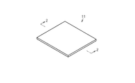
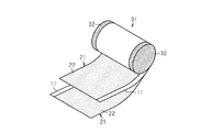
- FIG. 1 It is a schematic perspective view which shows the film for a film capacitor of an embodiment. It is sectional drawing which follows the line 2-2 of FIG. It is a perspective view which shows an example of the structure of a metallized film capacitor. It is a graph which shows the relationship between the depth and the oxygen atom concentration in the film for a film capacitor.
- the film capacitor 11 has a polypropylene base film 12 and oxide layers 13 provided on both the front and back surfaces of the base film 12.
- the base film 12 is preferably a biaxially stretched film.
- the biaxially stretched film is obtained by, for example, a tenter method or an inflation method.
- polypropylene constituting the base film 12 homopolypropylene which is a homopolymer of propylene, random polypropylene which is a random copolymer of propylene and ethylene, or block polypropylene which is a block copolymer of propylene and ethylene is used. Can be done. Peak top molecular weight of the polypropylene is preferably 10 6 or less. Peak top molecular weight of the polypropylene is preferably 10 5 or more. The peak top molecular weight of polypropylene can be determined from the molecular weight distribution measured by gel permeation chromatography (GPC).
- GPC gel permeation chromatography
- the base film 12 may contain additives such as antioxidants in addition to polypropylene.
- the content of the antioxidant contained in the base film 12 is preferably 1% by mass or less when the whole base film 12 is 100% by mass.
- the content of the antioxidant means the total content of the plurality of antioxidants when the base film 12 contains the plurality of antioxidants. Examples of the antioxidant include phenolic antioxidants, phosphorus-based antioxidants, sulfur-based antioxidants and the like.
- the content of the antioxidant can be determined according to a conventional method using qualitative analysis and quantitative analysis of (H 1 -NMR).
- the oxygen atom concentration of the oxide layer 13 is 10 21 atoms / cm 3 or more.
- the oxygen atom concentration of the oxide layer 13 is measured by using Secondary Ion Mass Spectrometry (SIMS).
- SIMS Secondary Ion Mass Spectrometry
- the oxygen atom concentration of the oxide layer 13 can be measured by using commercially available secondary ion mass spectrometry, for example, using Cs + as the primary ion species, under the condition of primary ion energy of 3 keV.
- the upper limit of the oxygen atom concentration of the oxide layer 13 is not particularly limited , but is preferably 10 23 atoms / cm 3 or less, and more preferably 10 22 atoms / cm 3 or less.
- the oxide layer 13 has a functional group containing oxygen.
- the functional group containing oxygen include a carbonyl group, a carboxy group, an ether group, and a hydroxy group.
- the oxide layer 13 is provided on both the front and back surfaces of the base film 12, but can be provided on at least one of the front and back surfaces of the base film 12.
- the oxygen atom concentration on the other outermost surface of the base film 12 is less than 10 21 atoms / cm 3.
- the oxide layer 13 on the front surface side of the base film 12 and the oxide layer 13 on the back surface side of the base film 12 have the same thickness. It may have different thicknesses from each other.
- the thickness of at least one of the two oxide layers 13, preferably both, is preferably 0.05 ⁇ m or more, more preferably 0.5 ⁇ m or more, from the viewpoint of further increasing the strength of dielectric breakdown. ..
- the thickness of the oxide layer 13 is preferably 70% or less, more preferably 60%, still more preferably 50, when the total thickness of the base film 12 and the oxide layer 13 is taken as 100%. % Or less.
- the total thickness of the base film 12 and the oxide layer 13 is preferably in the range of 1 ⁇ m or more and 20 ⁇ m or less.
- the thickness of the oxide layer 13 referred to here is the total thickness of the two oxide layers 13 and 13 when the oxide layers 13 are provided on both the front and back surfaces of the base film 12.
- the total thickness of the base film 12 and the oxide layer 13 is the thickness of the base film 12 and the oxide layers provided on both the front and back surfaces when the oxide layers 13 and 13 are provided on both the front and back surfaces of the base film 12. It is the total thickness of 13 and 13.
- the thickness of the oxide layer 13 is the depth from the outermost surface of the oxide layer 13, and can be confirmed by the above SIMS measurement.
- the oxygen atom concentration of the oxide layer 13 is, for example, the highest on the outermost surface of the oxide layer 13, and is 10 21 atoms / cm 3 at the boundary between the oxide layer 13 and the base film 12.
- the film 11 for a film capacitor can be obtained from a polypropylene film as a raw material.
- the oxide layer 13 of the film 11 for a film capacitor is formed by activating the surface of the polypropylene film and the atmospheric gas and binding oxygen in the atmospheric gas to at least one of the front and back surfaces of the polypropylene film. can do.
- Examples of the method for forming the oxide layer 13 include corona discharge treatment, electron beam irradiation, and plasma irradiation.
- the formation of the oxide layer 13 may be carried out in an ozone atmosphere from the viewpoint of further promoting oxidation.
- a metallized film 21 for a film capacitor can also be obtained from the film 11 for a film capacitor.
- the metallized film 21 for a film capacitor includes a film 11 for a film capacitor and a metal film 22 provided on the film 11 for a film capacitor.
- Examples of the metal of the metal film 22 include zinc, zinc-tin alloy, tin, copper, aluminum, and magnesium.
- the metal film 22 can be provided, for example, by a metal vapor deposition method.
- the metallized film 21 for a film capacitor of the present embodiment has a metal film 22 on one of the front and back surfaces of the film 11 for a film capacitor, but may have a metal film 22 on both the front and back surfaces.
- Examples of the layer structure of the metallized film 21 for a film capacitor include a three-layer structure of a base film 12 / oxide layer 13 / metal film 22 or a metal film 22 / base film 12 / oxide layer 13.
- a four-layer structure of the metal film 22 / oxide layer 13 / base film 12 / oxide layer 13 and the metal film 22 / oxide layer 13 / base film A five-layer structure of 12 / oxide layer 13 / metal film 22 can be mentioned.
- the film capacitor includes the film 11 for a film capacitor as a dielectric layer.
- Examples of the film capacitor include a metallized film capacitor, a foil-wrapped film capacitor, an oil-immersed film capacitor, and an oil-immersed paper film capacitor.
- FIG. 3 shows an example of the structure of a metallized film capacitor.
- the metallized film capacitor includes a winder 31 formed by winding a metallized film 21 for a film capacitor. More specifically, the winding body 31 is formed by winding two metallized films 21 for a film capacitor having a metal film 22 on one side as a set.
- the winding body 31 includes electrodes 32 and 32 provided at both ends in the width direction of the film. Examples of the metal of the electrodes 32 and 32 include zinc, zinc-tin alloy, tin, copper, aluminum, and magnesium.
- the electrodes 32 and 32 can be formed, for example, by thermal spraying of a metal.
- the winding body 31 can also be changed to a winding body formed by winding a metallized film for a film capacitor having metal films on both the front and back surfaces and a film 11 for a film capacitor as a set.
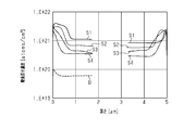
- FIG. 4 shows the relationship between the depths of the blanks and samples 1 to 4 and the oxygen atom concentration.
- B indicates a blank
- S1 to S4 indicate samples 1 to 4, respectively.
- the position where the depth is 0 ⁇ m in FIG. 4 indicates the position of the outermost surface of the film which is the irradiation side of the electron beam, and the position where the depth is 5 ⁇ m is the side opposite to the irradiation side of the electron beam. Indicates the position of the outermost surface of the film.
- an oxide layer having an oxygen atom concentration of 10 21 atoms / cm 3 or more is formed on both the front and back surfaces. Further, in Samples 1 to 4, the oxide layer having an oxygen atom concentration of 10 21 atoms / cm 3 or more had a thickness of 0.05 ⁇ m or more. Further, on the surface side of the samples 1 and 2, an oxide layer having the oxygen atom concentration was formed with a thickness of 0.5 ⁇ m or more.
- the film 11 for a film capacitor has a polypropylene base film 12 and an oxide layer 13 provided on at least one of the front and back surfaces of the base film 12.
- the oxygen atom concentration of the oxide layer 13 measured by the secondary ion mass spectrometry is 10 21 atoms / cm 3 or more. According to this configuration, even when the polypropylene base film 12 is used, the strength of dielectric breakdown of the film capacitor film 11 can be increased by providing the denser oxide layer 13.
- the oxide layer 13 having the above oxygen atom concentration is present on the surface of the base film 12, and the oxide layer 13 is in contact with the negative electrode, thereby increasing the strength of dielectric breakdown when a voltage is applied. be able to. It is considered that the reason why this effect can be obtained is that the presence of the oxide layer 13 increases the potential barrier against the injection of electrode electrons from the negative electrode into the film and suppresses the electron injection from the negative electrode when a voltage is applied. Be done.
- the energy density u of the film capacitor can be expressed by the following equation using the dielectric constant ⁇ of the dielectric and the applied electric field strength E.
- the applied electric field strength E in the above equation can be increased, so that the energy density u of the film capacitor can be increased. Therefore, according to the film capacitor 11 for film capacitors, even if the polypropylene base film 12 is used, a high energy density can be exhibited. This makes it possible to reduce the size of the film capacitor, for example.
- the base film 12 of the film capacitor 11 is made of polypropylene, the dielectric loss tangent (tan ⁇ ) of the film capacitor can be suppressed low. Therefore, the heat generation of the film capacitor can be suppressed.
- the thickness of the oxide layer 13 having the oxygen atom concentration is 0.05 ⁇ m or more, the strength of dielectric breakdown of the film 11 for a film capacitor can be further increased.
- the base film 12 can be easily formed.
- the total thickness of the base film 12 and the oxide layer 13 is 20 ⁇ m or less, for example, the capacitance can be further increased.
Landscapes
- Engineering & Computer Science (AREA)
- Power Engineering (AREA)
- Manufacturing & Machinery (AREA)
- Microelectronics & Electronic Packaging (AREA)
- Fixed Capacitors And Capacitor Manufacturing Machines (AREA)
- Laminated Bodies (AREA)
Abstract
フィルムコンデンサ用フィルムは、ポリプロピレン製の基材フィルムと、基材フィルムの表裏両面のうち少なくとも一方の面に設けられた酸化層とを有する。二次イオン質量分析法を用いて測定される酸化層の酸素原子濃度は、1021atoms/cm3以上である。
Description
本発明は、フィルムコンデンサ用フィルム、フィルムコンデンサ用金属化フィルム、及びフィルムコンデンサに関する。
比較的低い誘電正接(tanδ)を有するフィルムコンデンサ用フィルムとして、ポリプロピレンフィルムが知られている。また、ポリプロピレンフィルム以外のフィルムコンデンサ用フィルムとしては、比誘電率が高いポリフッ化ビニリデンフィルムや電気絶縁性に優れるポリエーテルケトンフィルムが知られている(特許文献1,2参照)。
上記のポリプロピレンフィルムは、比較的低い誘電正接(tanδ)を有することから、フィルムコンデンサの発熱を抑えるという観点で有利である。ところが、ポリプロピレンフィルムを用いたフィルムコンデンサのエネルギー密度は、ポリフッ化ビニリデンフィルムを用いたフィルムコンデンサのエネルギー密度よりも低い。このため、ポリプロピレンフィルムをフィルムコンデンサ用フィルムとして用いることは、例えば、フィルムコンデンサの小型化の観点では、必ずしも有利ではない。
本発明の目的は、ポリプロピレン製の基材フィルムを用いたとしても、高いエネルギー密度を発揮させることを可能にしたフィルムコンデンサ用フィルム、フィルムコンデンサ用金属化フィルム、及びフィルムコンデンサを提供することにある。
上記課題を解決するフィルムコンデンサ用フィルムは、ポリプロピレン製の基材フィルムと、前記基材フィルムの表裏両面のうち少なくとも一方の面に設けられた酸化層とを有し、二次イオン質量分析法を用いて測定される前記酸化層の酸素原子濃度は、1021atoms/cm3以上である。
上記フィルムコンデンサ用フィルムにおいて、前記酸化層は、0.05μm以上の厚さを有することが好ましい。
上記フィルムコンデンサ用フィルムにおいて、前記基材フィルムと前記酸化層との合計の厚さは、1μm以上、20μm以下の範囲内であることが好ましい。
フィルムコンデンサは、上記フィルムコンデンサ用フィルムを誘電体層として備える。
フィルムコンデンサ用金属化フィルムは、フィルムコンデンサ用フィルムと、前記フィルムコンデンサ用フィルム上に設けられた金属膜とを有し、前記フィルムコンデンサ用フィルムは、ポリプロピレン製の基材フィルムと、前記基材フィルムの表裏両面のうち少なくとも一方の面に設けられた酸化層とを有し、前記酸化層の酸素原子濃度が1021atoms/cm3以上である。
フィルムコンデンサは、上記フィルムコンデンサ用金属化フィルムを巻回してなる巻回体を備えてもよい。
以下、本発明の実施形態に係るフィルムコンデンサ用フィルム、フィルムコンデンサ用金属化フィルム、及びフィルムコンデンサについて説明する。
<フィルムコンデンサ用フィルム>
図1及び図2に示すように、フィルムコンデンサ用フィルム11は、ポリプロピレン製の基材フィルム12と、基材フィルム12の表裏両面に設けられた酸化層13とを有する。
図1及び図2に示すように、フィルムコンデンサ用フィルム11は、ポリプロピレン製の基材フィルム12と、基材フィルム12の表裏両面に設けられた酸化層13とを有する。
基材フィルム12は、二軸延伸フィルムであることが好ましい。二軸延伸フィルムは、例えば、テンター法又はインフレーション法により得られる。
基材フィルム12を構成するポリプロピレンとしては、プロピレンの単独重合体であるホモポリプロピレン、プロピレンとエチレンのランダム共重合体であるランダムポリプロピレン、又はプロピレンとエチレンのブロック共重合体であるブロックポリプロピレンを用いることができる。ポリプロピレンのピークトップ分子量は、106以下であることが好ましい。ポリプロピレンのピークトップ分子量は、105以上であることが好ましい。ポリプロピレンのピークトップ分子量は、ゲル浸透クロマトグラフィー(GPC)を用いて測定した分子量分布から求めることができる。
基材フィルム12には、ポリプロピレンの他に酸化防止剤等の添加剤が含有されていてもよい。但し、基材フィルム12に含まれる酸化防止剤の含有量は、基材フィルム12の全体を100質量%とした場合、1質量%以下であることが好ましい。酸化防止剤の含有量は、基材フィルム12が複数の酸化防止剤を含む場合、複数の酸化防止剤の合計の含有量をいう。酸化防止剤としては、フェノール系酸化防止剤、リン系酸化防止剤、硫黄系酸化防止剤等が挙げられる。酸化防止剤の含有量は、定性分析及び定量分析(H1-NMR)を用いた常法に従って求めることができる。
酸化層13の酸素原子濃度は、1021atoms/cm3以上である。酸化層13の酸素原子濃度は、二次イオン質量分析法(Secondary Ion Mass Spectrometry:SIMS)を用いて測定される。酸化層13の酸素原子濃度の測定は、市販の二次イオン質量分析を用いて、例えば、一次イオン種としてCs+を用いて、3keVの一次イオンエネルギーの条件で測定することができる。
なお、酸化層13の酸素原子濃度の上限は、特に限定されないが、例えば、1023atoms/cm3以下であることが好ましく、より好ましくは1022atoms/cm3以下である。
酸化層13は、酸素を含む官能基を有する。酸素を含む官能基としては、例えば、カルボニル基、カルボキシ基、エーテル基、及びヒドロキシ基が挙げられる。
酸化層13は、基材フィルム12の表裏両面に設けられているが、基材フィルム12の表裏両面のうち少なくとも一方の面に設けることができる。酸化層13を基材フィルム12の表裏両面のうちいずれか一方の面に設ける場合、基材フィルム12の他方の最外面の酸素原子濃度は、1021atoms/cm3未満である。
基材フィルム12の表裏両面に酸化層13を設ける場合、基材フィルム12の表面側の酸化層13と、基材フィルム12の裏面側の酸化層13とは、互いに同じ厚さを有していてもよいし、互いに異なる厚さを有していてもよい。2つの酸化層13のうち、少なくとも一方、好ましくは両方の厚さは、絶縁破壊の強さをより高めるという観点から、0.05μm以上であることが好ましく、より好ましくは0.5μm以上である。
酸化層13の厚さは、基材フィルム12と酸化層13との合計の厚さを100%としたときに70%以下であることが好ましく、より好ましくは60%であり、さらに好ましくは50%以下である。
フィルムコンデンサ用フィルム11において、基材フィルム12と酸化層13との合計の厚さは、1μm以上、20μm以下の範囲であることが好ましい。
ここでいう酸化層13の厚さは、基材フィルム12の表裏両面に酸化層13を設けた場合、2つの酸化層13,13の厚さの合計である。また、基材フィルム12と酸化層13との合計の厚さは、基材フィルム12の表裏両面に酸化層13,13を設けた場合、基材フィルム12の厚さと表裏両面に設けた酸化層13,13の厚さの合計である。
酸化層13の厚さは、酸化層13の最外面からの深さであり、上記SIMSの測定により確認することができる。酸化層13の酸素原子濃度は、例えば、酸化層13の最外面において最も高く、酸化層13と基材フィルム12との境界では、1021atoms/cm3となる。
<フィルムコンデンサ用フィルムの製造方法>
フィルムコンデンサ用フィルム11は、ポリプロピレン製のフィルムを原材料として得ることができる。フィルムコンデンサ用フィルム11の酸化層13は、ポリプロピレン製のフィルムの表面と雰囲気ガスとを活性化し、ポリプロピレン製のフィルムの表裏両面のうち少なくとも一方の面に雰囲気ガス中の酸素を結合させることで形成することができる。酸化層13を形成する方法としては、例えば、コロナ放電処理、電子線照射、及びプラズマ照射が挙げられる。酸化層13の形成は、酸化をより促進するという観点から、オゾン雰囲気下で行ってもよい。
フィルムコンデンサ用フィルム11は、ポリプロピレン製のフィルムを原材料として得ることができる。フィルムコンデンサ用フィルム11の酸化層13は、ポリプロピレン製のフィルムの表面と雰囲気ガスとを活性化し、ポリプロピレン製のフィルムの表裏両面のうち少なくとも一方の面に雰囲気ガス中の酸素を結合させることで形成することができる。酸化層13を形成する方法としては、例えば、コロナ放電処理、電子線照射、及びプラズマ照射が挙げられる。酸化層13の形成は、酸化をより促進するという観点から、オゾン雰囲気下で行ってもよい。
<フィルムコンデンサ用金属化フィルム及びその製造方法>
図3に示すように、フィルムコンデンサ用フィルム11からフィルムコンデンサ用金属化フィルム21を得ることもできる。フィルムコンデンサ用金属化フィルム21は、フィルムコンデンサ用フィルム11と、フィルムコンデンサ用フィルム11上に設けられた金属膜22とを備える。金属膜22の金属としては、例えば、亜鉛、亜鉛・錫合金、錫、銅、アルミニウム、及びマグネシウムが挙げられる。金属膜22は、例えば、金属蒸着法により設けることができる。本実施形態のフィルムコンデンサ用金属化フィルム21は、フィルムコンデンサ用フィルム11の表裏両面のうち一方の面に金属膜22を有しているが、表裏両面に金属膜22を有していてもよい。フィルムコンデンサ用金属化フィルム21の層構造の例としては、基材フィルム12/酸化層13/金属膜22、又は金属膜22/基材フィルム12/酸化層13の三層構造が挙げられる。フィルムコンデンサ用金属化フィルム21の層構造の別の例としては、金属膜22/酸化層13/基材フィルム12/酸化層13の四層構造、及び金属膜22/酸化層13/基材フィルム12/酸化層13/金属膜22の五層構造が挙げられる。
図3に示すように、フィルムコンデンサ用フィルム11からフィルムコンデンサ用金属化フィルム21を得ることもできる。フィルムコンデンサ用金属化フィルム21は、フィルムコンデンサ用フィルム11と、フィルムコンデンサ用フィルム11上に設けられた金属膜22とを備える。金属膜22の金属としては、例えば、亜鉛、亜鉛・錫合金、錫、銅、アルミニウム、及びマグネシウムが挙げられる。金属膜22は、例えば、金属蒸着法により設けることができる。本実施形態のフィルムコンデンサ用金属化フィルム21は、フィルムコンデンサ用フィルム11の表裏両面のうち一方の面に金属膜22を有しているが、表裏両面に金属膜22を有していてもよい。フィルムコンデンサ用金属化フィルム21の層構造の例としては、基材フィルム12/酸化層13/金属膜22、又は金属膜22/基材フィルム12/酸化層13の三層構造が挙げられる。フィルムコンデンサ用金属化フィルム21の層構造の別の例としては、金属膜22/酸化層13/基材フィルム12/酸化層13の四層構造、及び金属膜22/酸化層13/基材フィルム12/酸化層13/金属膜22の五層構造が挙げられる。
<フィルムコンデンサ>
フィルムコンデンサは、上記フィルムコンデンサ用フィルム11を誘電体層として備える。フィルムコンデンサとしては、例えば、金属化フィルムコンデンサ、箔巻きフィルムコンデンサ、油浸フィルムコンデンサ、及び油浸紙フィルムコンデンサが挙げられる。
フィルムコンデンサは、上記フィルムコンデンサ用フィルム11を誘電体層として備える。フィルムコンデンサとしては、例えば、金属化フィルムコンデンサ、箔巻きフィルムコンデンサ、油浸フィルムコンデンサ、及び油浸紙フィルムコンデンサが挙げられる。
図3には、金属化フィルムコンデンサの構造の一例を示している。金属化フィルムコンデンサは、フィルムコンデンサ用金属化フィルム21を巻回してなる巻回体31を備えている。詳述すると、巻回体31は、片面に金属膜22を有するフィルムコンデンサ用金属化フィルム21の二枚を一組として巻回することで形成される。巻回体31は、フィルムの幅方向の両端部に設けられた電極32,32を備えている。電極32,32の金属としては、例えば、亜鉛、亜鉛・錫合金、錫、銅、アルミニウム、及びマグネシウムが挙げられる。電極32,32は、例えば、金属の溶射により形成することができる。なお、巻回体31は、表裏両面に金属膜を有するフィルムコンデンサ用金属化フィルムと、フィルムコンデンサ用フィルム11とを一組として巻回してなる巻回体に変更することもできる。
<試作例>
次に、試作例について説明する。
次に、試作例について説明する。
(フィルムコンデンサ用フィルムのサンプルの作製)
ポリプロピレン製のフィルム(二軸延伸ポリプロピレンフィルム、厚さ5μm、A4サイズ)の片面に電子線照射装置を用いて電子線を大気雰囲気下で照射することで、フィルムコンデンサ用フィルムのサンプル1~4を作製した。電子線照射の条件を表1に示す。表1中のブランクは、電子線を照射する前のフィルムである。
ポリプロピレン製のフィルム(二軸延伸ポリプロピレンフィルム、厚さ5μm、A4サイズ)の片面に電子線照射装置を用いて電子線を大気雰囲気下で照射することで、フィルムコンデンサ用フィルムのサンプル1~4を作製した。電子線照射の条件を表1に示す。表1中のブランクは、電子線を照射する前のフィルムである。

ブランク及びサンプル1~4の酸素原子濃度をSIMSにより測定した。
図4には、ブランク及びサンプル1~4の深さと酸素原子濃度との関係を示している。図4中、Bは、ブランクを示し、S1~S4は、それぞれサンプル1~4を示す。また、図4の深さが0μmの位置は、上記の電子線の照射側となるフィルムの最外面の位置を示し、深さが5μmの位置は、電子線の照射側とは反対側となるフィルムの最外面の位置を示す。
図4に示されるように、サンプル1~4では、表裏両面の両面側に酸素原子濃度が1021atoms/cm3以上の酸化層が形成されていることが分かる。また、サンプル1~4において、酸素原子濃度が1021atoms/cm3以上の酸化層は、厚さが0.05μm以上であった。また、サンプル1,2の表面側には、上記酸素原子濃度を有する酸化層が0.5μm以上の厚さで形成されていた。
(サンプルの絶縁破壊の強さの測定)
ブランク及びサンプル1~4について、JIS C2151:2006(IEC 60674-2:1988に対応)に準拠して絶縁破壊の強さを測定した。ブランク及びサンプル1~4について、それぞれ50点測定し、上位5点及び下位5点を除外した40点の平均値を算出した。その結果を表1に示す。
ブランク及びサンプル1~4について、JIS C2151:2006(IEC 60674-2:1988に対応)に準拠して絶縁破壊の強さを測定した。ブランク及びサンプル1~4について、それぞれ50点測定し、上位5点及び下位5点を除外した40点の平均値を算出した。その結果を表1に示す。
表1に示すように、サンプル1~4では、絶縁破壊の強さがブランクよりも高い結果が得られた。また、サンプル1,2では、絶縁破壊の強さがサンプル3,4よりも高い結果が得られた。
次に、本実施形態の作用及び効果について説明する。
(1)フィルムコンデンサ用フィルム11は、ポリプロピレン製の基材フィルム12と、基材フィルム12の表裏両面のうち少なくとも一方の面に設けられた酸化層13とを有している。二次イオン質量分析法を用いて測定される酸化層13の酸素原子濃度は、1021atoms/cm3以上である。この構成によれば、ポリプロピレン製の基材フィルム12を用いた場合であっても、より緻密な酸化層13を設けることで、フィルムコンデンサ用フィルム11の絶縁破壊の強さを高めることができる。
詳述すると、基材フィルム12の表面に上記の酸素原子濃度を有する酸化層13が存在し、酸化層13が負極電極と接触していることにより、電圧印加時の絶縁破壊の強さを高めることができる。この効果が得られる理由としては、上記酸化層13の存在によって負極内からフィルム内への電極電子の注入に対する電位障壁が大きくなり、電圧印加時に負極電極からの電子注入が抑制されるためと考えられる。
ここで、フィルムコンデンサのエネルギー密度uは、誘電体の誘電率ε、及び印加電界強度Eを用いて下記式で表すことができる。
u=1/2×ε×E2
コンデンサ用フィルムの絶縁破壊の強さが高まるほど、上記式中の印加電界強度Eを上げることができるので、フィルムコンデンサのエネルギー密度uを高くすることができる。従って、上記フィルムコンデンサ用フィルム11によれば、ポリプロピレン製の基材フィルム12を用いたとしても、高いエネルギー密度を発揮させることが可能となる。これにより、例えば、フィルムコンデンサを小型化することが可能となる。
コンデンサ用フィルムの絶縁破壊の強さが高まるほど、上記式中の印加電界強度Eを上げることができるので、フィルムコンデンサのエネルギー密度uを高くすることができる。従って、上記フィルムコンデンサ用フィルム11によれば、ポリプロピレン製の基材フィルム12を用いたとしても、高いエネルギー密度を発揮させることが可能となる。これにより、例えば、フィルムコンデンサを小型化することが可能となる。
また、フィルムコンデンサ用フィルム11の基材フィルム12は、ポリプロピレン製であるため、フィルムコンデンサの誘電正接(tanδ)を低く抑えることができる。従って、フィルムコンデンサの発熱を抑えることができる。
(2)上記酸素原子濃度を有する酸化層13の厚さが0.05μm以上の場合、フィルムコンデンサ用フィルム11の絶縁破壊の強さをより高めることができる。
(3)基材フィルム12と酸化層13との合計の厚さが1μm以上の場合、例えば、基材フィルム12の製膜が容易となる。基材フィルム12と酸化層13との合計の厚さが20μm以下の場合、例えば、静電容量をより高めることができる。
Claims (6)
- ポリプロピレン製の基材フィルムと、前記基材フィルムの表裏両面のうち少なくとも一方の面に設けられた酸化層とを有し、
二次イオン質量分析法を用いて測定される前記酸化層の酸素原子濃度は、1021atoms/cm3以上である、フィルムコンデンサ用フィルム。 - 前記酸化層は、0.05μm以上の厚さを有する、請求項1に記載のフィルムコンデンサ用フィルム。
- 前記基材フィルムと前記酸化層との合計の厚さは、1μm以上、20μm以下の範囲内である、請求項1又は請求項2に記載のフィルムコンデンサ用フィルム。
- 請求項1から請求項3のいずれか一項に記載のフィルムコンデンサ用フィルムを誘電体層として備える、フィルムコンデンサ。
- フィルムコンデンサ用フィルムと、前記フィルムコンデンサ用フィルム上に設けられた金属膜とを有し、前記フィルムコンデンサ用フィルムは、ポリプロピレン製の基材フィルムと、前記基材フィルムの表裏両面のうち少なくとも一方の面に設けられた酸化層とを有し、
前記酸化層の酸素原子濃度が1021atoms/cm3以上である、フィルムコンデンサ用金属化フィルム。 - 請求項5に記載のフィルムコンデンサ用金属化フィルムを巻回してなる巻回体を備える、フィルムコンデンサ。
Priority Applications (1)
| Application Number | Priority Date | Filing Date | Title |
|---|---|---|---|
| PCT/JP2020/012307 WO2021186674A1 (ja) | 2020-03-19 | 2020-03-19 | フィルムコンデンサ用フィルム、フィルムコンデンサ用金属化フィルム、及びフィルムコンデンサ |
Applications Claiming Priority (1)
| Application Number | Priority Date | Filing Date | Title |
|---|---|---|---|
| PCT/JP2020/012307 WO2021186674A1 (ja) | 2020-03-19 | 2020-03-19 | フィルムコンデンサ用フィルム、フィルムコンデンサ用金属化フィルム、及びフィルムコンデンサ |
Publications (1)
| Publication Number | Publication Date |
|---|---|
| WO2021186674A1 true WO2021186674A1 (ja) | 2021-09-23 |
Family
ID=77771976
Family Applications (1)
| Application Number | Title | Priority Date | Filing Date |
|---|---|---|---|
| PCT/JP2020/012307 Ceased WO2021186674A1 (ja) | 2020-03-19 | 2020-03-19 | フィルムコンデンサ用フィルム、フィルムコンデンサ用金属化フィルム、及びフィルムコンデンサ |
Country Status (1)
| Country | Link |
|---|---|
| WO (1) | WO2021186674A1 (ja) |
Cited By (1)
| Publication number | Priority date | Publication date | Assignee | Title |
|---|---|---|---|---|
| JP2022042914A (ja) * | 2020-09-03 | 2022-03-15 | 広東以色列理工学院 | 耐高温の変性ポリプロピレンフィルム、その製造方法及び使用 |
Citations (7)
| Publication number | Priority date | Publication date | Assignee | Title |
|---|---|---|---|---|
| JPS50109143U (ja) * | 1974-02-14 | 1975-09-06 | ||
| JPS54109160A (en) * | 1978-02-15 | 1979-08-27 | Toray Industries | Polypropyrene film for capacitor |
| JPS5968919A (ja) * | 1982-10-12 | 1984-04-19 | 日新電機株式会社 | ポリプロピレンフイルムコンデンサ |
| JPS60170229A (ja) * | 1984-02-14 | 1985-09-03 | 松下電器産業株式会社 | 金属化フイルムコンデンサ |
| JPS62164732A (ja) * | 1986-01-14 | 1987-07-21 | Toray Ind Inc | 二軸延伸ポリプロピレンフイルム |
| WO2014142264A1 (ja) * | 2013-03-15 | 2014-09-18 | 東レ株式会社 | コンデンサ用二軸配向ポリプロピレンフィルム、金属化フィルム、およびフィルムコンデンサ |
| JP2014231604A (ja) * | 2009-03-17 | 2014-12-11 | 株式会社プライムポリマー | フィルムコンデンサ用ポリプロピレン、フィルムコンデンサ用ポリプロピレンシート、それらの製造方法、およびその用途 |
-
2020
- 2020-03-19 WO PCT/JP2020/012307 patent/WO2021186674A1/ja not_active Ceased
Patent Citations (7)
| Publication number | Priority date | Publication date | Assignee | Title |
|---|---|---|---|---|
| JPS50109143U (ja) * | 1974-02-14 | 1975-09-06 | ||
| JPS54109160A (en) * | 1978-02-15 | 1979-08-27 | Toray Industries | Polypropyrene film for capacitor |
| JPS5968919A (ja) * | 1982-10-12 | 1984-04-19 | 日新電機株式会社 | ポリプロピレンフイルムコンデンサ |
| JPS60170229A (ja) * | 1984-02-14 | 1985-09-03 | 松下電器産業株式会社 | 金属化フイルムコンデンサ |
| JPS62164732A (ja) * | 1986-01-14 | 1987-07-21 | Toray Ind Inc | 二軸延伸ポリプロピレンフイルム |
| JP2014231604A (ja) * | 2009-03-17 | 2014-12-11 | 株式会社プライムポリマー | フィルムコンデンサ用ポリプロピレン、フィルムコンデンサ用ポリプロピレンシート、それらの製造方法、およびその用途 |
| WO2014142264A1 (ja) * | 2013-03-15 | 2014-09-18 | 東レ株式会社 | コンデンサ用二軸配向ポリプロピレンフィルム、金属化フィルム、およびフィルムコンデンサ |
Cited By (2)
| Publication number | Priority date | Publication date | Assignee | Title |
|---|---|---|---|---|
| JP2022042914A (ja) * | 2020-09-03 | 2022-03-15 | 広東以色列理工学院 | 耐高温の変性ポリプロピレンフィルム、その製造方法及び使用 |
| JP7166317B2 (ja) | 2020-09-03 | 2022-11-07 | 広東以色列理工学院 | 耐高温の変性ポリプロピレンフィルム、その製造方法及び使用 |
Similar Documents
| Publication | Publication Date | Title |
|---|---|---|
| CN103930960B (zh) | 薄膜电容器 | |
| KR980700671A (ko) | 전기 커패시터용 금속박막 (metallized film for electrical capacitors) | |
| JP6167306B2 (ja) | 金属化フィルムコンデンサ | |
| KR20080072726A (ko) | 적층형 필름 콘덴서의 제조 방법 | |
| US20080232026A1 (en) | Thin film capacitor and methods of making same | |
| CN108701544A (zh) | 电容器 | |
| JP7461091B1 (ja) | 電極材料、電解コンデンサ用陰極箔、及び電解コンデンサ | |
| JP2014107394A (ja) | 金属化フィルムコンデンサ | |
| JP3769842B2 (ja) | 金属蒸着フィルム、その製造方法、およびそれを用いたコンデンサ | |
| TW202420351A (zh) | 電極材料、電解電容器用陰極箔及電解電容器 | |
| JP5934881B2 (ja) | 金属化フィルムコンデンサ | |
| JP7477898B2 (ja) | 電解コンデンサ用陰極箔、及び電解コンデンサ | |
| JP5299863B2 (ja) | 金属蒸着フィルム、及びその製造方法 | |
| JP2018107273A (ja) | 金属化フィルムコンデンサおよびその製造方法 | |
| JP2015216312A (ja) | フィルムコンデンサ | |
| JP5903647B2 (ja) | 金属化フィルムコンデンサ | |
| JPH0126523B2 (ja) | ||
| KR102815854B1 (ko) | 필름 커패시터용 하이브리드 금속필름 형성방법 | |
| JPH0158852B2 (ja) | ||
| KR102770028B1 (ko) | 고유전체 적용 다층 유전체 구조의 금속필름을 갖는 필름커패시터 | |
| JP2013214688A (ja) | フィルムコンデンサ | |
| JP5927481B2 (ja) | 金属化フィルムコンデンサ | |
| WO2025182418A1 (ja) | フィルムコンデンサ及び金属化フィルム | |
| JPS60182714A (ja) | コンデンサの製造方法 | |
| JPS6142118A (ja) | 油含浸型コンデンサ− |
Legal Events
| Date | Code | Title | Description |
|---|---|---|---|
| 121 | Ep: the epo has been informed by wipo that ep was designated in this application |
Ref document number: 20926022 Country of ref document: EP Kind code of ref document: A1 |
|
| NENP | Non-entry into the national phase |
Ref country code: DE |
|
| 122 | Ep: pct application non-entry in european phase |
Ref document number: 20926022 Country of ref document: EP Kind code of ref document: A1 |
|
| NENP | Non-entry into the national phase |
Ref country code: JP |