WO2021186568A1 - アンテナ装置 - Google Patents
アンテナ装置 Download PDFInfo
- Publication number
- WO2021186568A1 WO2021186568A1 PCT/JP2020/011768 JP2020011768W WO2021186568A1 WO 2021186568 A1 WO2021186568 A1 WO 2021186568A1 JP 2020011768 W JP2020011768 W JP 2020011768W WO 2021186568 A1 WO2021186568 A1 WO 2021186568A1
- Authority
- WO
- WIPO (PCT)
- Prior art keywords
- antenna
- heat pipe
- heat
- antenna device
- adapter
- Prior art date
- Legal status (The legal status is an assumption and is not a legal conclusion. Google has not performed a legal analysis and makes no representation as to the accuracy of the status listed.)
- Ceased
Links
Images







Classifications
-
- H—ELECTRICITY
- H01—ELECTRIC ELEMENTS
- H01Q—ANTENNAS, i.e. RADIO AERIALS
- H01Q1/00—Details of, or arrangements associated with, antennas
- H01Q1/02—Arrangements for de-icing; Arrangements for drying-out ; Arrangements for cooling; Arrangements for preventing corrosion
-
- B—PERFORMING OPERATIONS; TRANSPORTING
- B60—VEHICLES IN GENERAL
- B60R—VEHICLES, VEHICLE FITTINGS, OR VEHICLE PARTS, NOT OTHERWISE PROVIDED FOR
- B60R11/00—Arrangements for holding or mounting articles, not otherwise provided for
- B60R11/02—Arrangements for holding or mounting articles, not otherwise provided for for radio sets, television sets, telephones, or the like; Arrangement of controls thereof
-
- H—ELECTRICITY
- H01—ELECTRIC ELEMENTS
- H01Q—ANTENNAS, i.e. RADIO AERIALS
- H01Q1/00—Details of, or arrangements associated with, antennas
- H01Q1/27—Adaptation for use in or on movable bodies
- H01Q1/32—Adaptation for use in or on road or rail vehicles
-
- H—ELECTRICITY
- H01—ELECTRIC ELEMENTS
- H01Q—ANTENNAS, i.e. RADIO AERIALS
- H01Q1/00—Details of, or arrangements associated with, antennas
- H01Q1/42—Housings not intimately mechanically associated with radiating elements, e.g. radome
Definitions
- the present disclosure relates to an array-type antenna device mounted on a mobile body.
- the mechanically driven antenna device In order to reduce air resistance, it is necessary to reduce the cross-sectional area (hereinafter referred to as the projected area) of the moving body seen from the front in the traveling direction, or to have a streamlined shape to reduce the separation of the wake. Since it is necessary, the installation space of the antenna device is limited in the moving body.
- the opening surface of the antenna body and the reflecting plate are mechanically driven to control the directivity, so that the mechanical driving device is approximately several tens of centimeters high to be housed in the antenna device. Was needed. Therefore, when the mechanically driven antenna device is mounted on the moving body, there is a limit to the reduction of air resistance.
- the phased array type antenna device includes an antenna array in which a plurality of antenna elements are regularly arranged, and the antenna array electronically controls the directivity by individually phase-controlling the signals transmitted and received by each antenna element. It is possible to reduce the thickness of the entire antenna device.
- the phased array type antenna device in order to increase the communication speed and the communication capacity, it is necessary to increase the frequency of the signal and the antenna element to be highly integrated, and the heat generation density is higher than that of the conventional mechanically driven antenna device. Will be higher. Further, since the antenna element is composed of a semiconductor, it is necessary to sufficiently cool the element and keep the junction temperature at about 100 ° C. or lower in order to obtain desired performance.
- a method of dissipating heat by the running wind obtained by the movement of the moving body has been developed.
- a wiring board, a plurality of antenna elements, a plurality of antenna element operation modules, and a plurality of antenna elements arranged in a predetermined arrangement on one surface of the wiring board are accommodated. It includes an exterior plate on which a plurality of antenna element accommodating holes are formed. The exterior plate is attached to the surface of the moving body with one surface exposed to the external space, transfers the heat generated by the antenna element operation module to the wiring board and the exterior plate, and moves one surface of the exterior plate as the moving body moves. Heat is dissipated from the exterior plate by the flowing air flow.
- Patent Document 2 describes a device that dissipates heat to the inside of a moving body by using a refrigerant pipe and a pump.
- the antenna device When the moving body is moving at high speed, the antenna device is cooled by the obtained running wind.
- the antenna device since the antenna device is covered with a radome and does not come into direct contact with the outside air, it is necessary to transport heat to the external space of the antenna device via an antenna adapter made of a good heat conductive material.
- the antenna adapter cannot be made thick with a thin antenna device, there is a problem that the heat in the central part of the array cannot be sufficiently diffused by the antenna adapter and sufficient heat cannot be dissipated.
- Patent Document 2 is excellent in that it can stably dissipate heat even when the moving body is stopped.
- the pump since the pump is used as a mechanical component, its maintenance is required.
- the purpose of this disclosure is to improve the cooling performance of the thin antenna device without maintenance.
- the antenna device is arranged so as to cover an antenna array having an antenna element that transmits or receives radio waves for communication, an antenna adapter that holds the antenna array and has a gap with the surface of a moving body, and an antenna adapter.
- a skirt that shields outside air from flowing into the gap between the antenna adapter and the surface of the moving object, and a skirt that dissipates heat from the antenna adapter, and a condensing unit that condenses the working fluid vaporized by the evaporating part and the evaporating part. It is equipped with a heat pipe, which is arranged so as to extend from the antenna array toward the skirt.
- FIG. 1 It is a perspective view which shows the appearance of the antenna device which concerns on Embodiment 1.
- FIG. 2 is a perspective view which shows the inside of the antenna device which concerns on Embodiment 1.
- FIG. It is a perspective view which shows the antenna array which concerns on Embodiment 1.
- FIG. It is a figure which showed the coupling structure of the antenna adapter and the mounting bracket which concerns on Embodiment 1.
- FIG. It is a figure which looked at a part of the antenna device from the PP'line of FIG.
- FIG. It is a perspective view which shows the arrangement of the heat pipe which concerns on Embodiment 1.
- FIG. It is a figure which looked at the antenna device from the line AA'in FIG.
- It is a figure which looked at the antenna device from the BB'line of FIG.
- FIG. 5 is a view of the antenna device viewed from the line AA'of FIG. 6 when the heat pipe according to the first embodiment is installed at an angle. It is sectional drawing of the heat pipe which concerns on Embodiment 1.
- FIG. It is a figure which shows the modification of the antenna device which concerns on Embodiment 1.
- FIG. It is a perspective view which shows the arrangement of the heat pipe which concerns on Embodiment 2.
- FIG. It is sectional drawing of the heat pipe which concerns on Embodiment 2.
- FIG. It is a perspective view which shows the arrangement of the heat pipe which concerns on Embodiment 3.
- FIG. 3 shows the arrangement of the heat pipe which concerns on Embodiment 3.
- FIG. 1 is a perspective view showing the appearance of the antenna device 100 according to the first embodiment.
- FIG. 2 is a perspective view showing the inside of the antenna device 100 according to the first embodiment. The basic configuration of the antenna device 100 according to the first embodiment will be described with reference to FIGS. 1 and 2.
- the surface of the antenna device 100 is surrounded by the radome 3 and the skirt 4, and the radome 3, the skirt 4 and the moving body surface 7 are in close contact with each other. Therefore, even when the moving body moves at high speed, the traveling wind does not enter the inside of the antenna device 100.
- the antenna device 100 includes an antenna array 1, an antenna adapter 2, a radome 3, a skirt 4, a power supply 6, and a control circuit 8.
- the antenna device 100 is attached to the surface 7 of a mobile body such as an aircraft and is used for communication using an artificial satellite.
- the direction orthogonal to the moving body surface 7 is defined as the Z axis
- the traveling direction of the moving body is defined as the Y axis
- the width direction of the antenna device 100 orthogonal to them is defined as the X axis.
- the positive direction of the Z axis is referred to as "up”
- the negative direction is referred to as "down”
- the positive direction of the Y axis is referred to as "front”
- the negative direction of the Y axis is referred to as "back”.
- the traveling direction of the moving body shall coincide with the direction in which the front part to the rear part of the moving body are connected by a straight line, and if the moving body is, for example, an aircraft, it coincides with the direction from the nose to the tail wing. do.
- the moving body according to the first embodiment will be described as an aircraft, the moving body is merely an example, and the moving body is not limited to the aircraft.
- FIG. 3 is a schematic view of the antenna array 1 according to the first embodiment.
- the antenna array 1 is a flat plate type communication module, and includes a transmission antenna array 1a for transmitting radio waves to a communication target and a reception antenna array 1b for receiving radio waves from the communication target.
- the transmitting antenna array 1a and the receiving antenna array 1b are arranged on the antenna adapter 2 at intervals from each other. That is, the antenna array 1 is held by the antenna adapter 2.
- the receiving antenna array 1b is arranged on the ⁇ Y axis side of the transmitting antenna array 1a, but the present invention is not limited to this.
- the receiving antenna array 1b may be arranged on the + Y-axis side of the transmitting antenna array 1a. Further, since the transmitting antenna array 1a and the receiving antenna array 1b generate heat due to the transmission or reception of radio waves, they are installed apart from each other.
- the antenna array 1 includes a plurality of antenna elements 13 arranged in a grid pattern and a communication IC 12 that causes the antenna elements 13 to perform a predetermined operation.
- the antenna array 1 is an active electronic scanning antenna array, and adjusts the directivity of radio waves by controlling the phase shift amount of each antenna element 13 in order to track an artificial satellite to be communicated.
- the antenna elements 13 are arranged on a wiring board (not shown) and transmit or receive radio waves for communication to a communication target.
- An RF signal Radio Frequency
- the antenna element 13 generates heat when transmitting and receiving radio waves to and from the communication target. Since a plurality of antenna elements 13 are arranged in the antenna array 1, the heat generation density of the antenna array 1 may increase due to the high integration of the antenna elements 13.
- the number of antenna elements 13 arranged in the antenna array 1 is determined by the scanning angle of radio waves, the estimated amount of loss of radio waves, and the like. Further, the distance between the antenna elements 13 differs depending on the wavelength of the radio wave used for communication. The shorter the wavelength of the radio wave used for communication, the narrower the element spacing of the antenna element 13. For example, when the wavelength of the radio wave used for communication is the Ka band antenna element 13, the size of the antenna array 1 is about several tens of centimeters square.
- the communication IC 12 has a surface facing the surface in contact with the wiring board (not shown) in which the antenna elements 13 are arranged as a heat radiating surface, and the heat radiating surface is arranged so as to be joined to the antenna adapter 2.
- the communication IC 12 includes electronic components such as a phase device that changes the phase of the RF signal transmitted and received by the antenna element 13 and an amplifier that amplifies the RF signal. These electronic components are mounted on a wiring board, are supplied with a required power supply voltage from the power supply 6, and are further supplied with a required control signal from the control circuit 8 to execute a predetermined operation. Each electronic component of the communication IC 12 generates heat during operation.
- the calorific value of the communication IC 12 also differs depending on the semiconductor process of the electronic component. For example, when the heat generation amount of the communication IC 12 is in the kilowatt class, if the heat diffusion ability of the antenna adapter 2 in contact with the heat dissipation surface of the communication IC 12 is low, the central portion of the flat communication IC 12 cannot sufficiently dissipate heat. .. Since each electronic component included in the communication IC 12 is a semiconductor element, it is necessary to keep the junction temperature at about 100 ° C. or lower in order for the communication IC 12 to exhibit the desired performance. The junction temperature is the maximum temperature at which the semiconductor element operates. Therefore, in order for the communication IC 12 to operate, the heat dissipation performance of the antenna adapter 2 which is the heat dissipation surface of the communication IC 12 is important.
- the antenna adapter 2 is, for example, a flat base material, and is horizontally arranged on the upper surface of the moving body. Further, the antenna adapter 2 has a gap with the moving body surface 7 and faces the moving body surface 7. Therefore, the antenna adapter 2 has a surface on the side where the antenna array 1 is arranged (+ Z-axis side surface) and a surface on the side facing the moving body surface 7 (-Z-axis side surface), and faces the moving body surface 7.
- a power supply 6 for supplying electric power to the antenna array 1 and a control circuit 8 for transmitting a control signal to the antenna array 1 are arranged on the surface (the side surface of the ⁇ Z axis).
- the power supply 6 converts the power supply voltage supplied from the moving body into the voltages required by the antenna array 1 and the control circuit 8 and supplies them.
- the power supply 6 is composed of a plurality of elements, each of which is fixed to the antenna adapter 2. In the power source 6, heat is generated according to the electric power to be converted.
- the control circuit 8 is a circuit that controls the antenna array 1.
- a plurality of electronic components are mounted on the control circuit 8, and heat is generated by the operation.
- the antenna adapter 2 is provided with a plurality of through holes 11 penetrating the surface on the side where the antenna array 1 is arranged (+ Z-axis side surface) and the surface on the side facing the moving body surface 7 (-Z-axis side surface). ing.
- the plurality of through holes 11 have different sizes depending on their roles, and most of them are provided to reduce the weight of the antenna adapter 2. Therefore, the antenna adapter 2 can be said to be a frame in which a plurality of holes are provided in the flat plate. Further, some through holes 11 provided on the outer peripheral portion of the antenna adapter 2 are provided with receiving metal fittings (not shown) into which the mounting metal fittings 5a to 5f are fitted.
- the antenna adapter 2 is fixed and supported by, for example, a plurality of mounting brackets 5a to 5d provided on the surface 7 of the moving body. ..
- the force applied to each fixed portion of the antenna adapter 2 is dispersed by the lift.
- the antenna adapter 2 and the moving body surface 7 are fixed and supported by the plurality of mounting brackets 5a to 5d, there is a gap between the antenna adapter 2 and the moving body surface 7.
- the antenna adapter 2 also plays a role of ensuring rigidity so that the entire antenna device 100 is not deformed by lift.
- the antenna adapter 2 is formed by carving out a material having high thermal conductivity. For example, it is a metal material such as aluminum. Therefore, the antenna adapter 2 serves as a heat dissipation path for heat generated in the antenna array 1, the power supply 6, the control circuit 8, and the like.
- the radome 3 is arranged so as to cover the antenna adapter 2 so as to have a gap with the surface (+ Z-axis side surface) on the side where the antenna array 1 of the antenna adapter 2 is arranged, and the antenna array 1 is disturbed by wind, rain, dust, etc. Plays a role in protecting from.
- the radome 3 is continuously connected to the skirt 4 and is fixed to the outer peripheral portion of the antenna adapter 2 by using a plurality of screws.
- the shape of the radome 3 is streamlined.
- the radome 3 since the radome 3 needs to transmit the radio waves transmitted and received by the antenna array 1 to the communication target, the radome 3 is made of a material capable of transmitting the radio waves used for communication. Therefore, as the material of the radome 3, for example, a resin material having a low dielectric constant and easily transmitting radio waves is used. With this configuration, even when the moving body moves at high speed, the air resistance generated in the antenna device 100 attached to the moving body surface 7 can be minimized.
- the skirt 4 is a flat plate provided along the outer circumference of the antenna adapter 2. As shown in FIG. 2, for example, when the antenna adapter 2 has an elliptical shape, the skirt 4 has a hollow elliptical frustum shape.
- the skirt 4 plays a role of preventing outside air from flowing into the gap between the antenna adapter 2 and the moving body surface 7.
- An elastic body 14 such as a rubber packing is attached to the connection between the skirt 4 and the surface 7 of the moving body so as to be in close contact with the surface 7 of the moving body. Since the skirt 4 is provided in close contact with the moving body surface 7, the moving body expands due to pressurization or the like, and even when the moving body surface 7 bends, outside air is introduced into the gap between the antenna adapter 2 and the moving body surface 7. It prevents the inflow.
- the skirt 4 is a member that connects the radome 3 and the moving body surface 7, outside air does not flow into the gap between the antenna adapter 2 and the moving body surface 7, and dew condensation that occurs inside the antenna device 100 is significantly increased. It becomes possible to reduce to.
- the outside air is the air outside the space enclosed by the radome 3, the skirt 4, and the surface 7 of the moving body, which are the outer skins of the antenna device 100. That is, it refers to the air outside the antenna device 100.
- the radome 3 and the skirt 4 have an outer shape symmetrical with respect to the center line AA'direction connecting the front part and the rear part of the moving body, for example.
- the transmitting antenna array 1a and the receiving antenna array 1b are respectively arranged on the surface of the antenna adapter 2 so as to be located on the center line AA'.
- the antenna adapter 2 is a heat radiating surface of a heating element such as an antenna element 13 and is a material having high thermal conductivity, the heat diffusion ability can be improved by increasing the thickness and the cross-sectional area. That is, it is possible to improve the heat dissipation performance by enlarging the heat dissipation surface.
- an increase in the cross-sectional area of the antenna adapter 2 results in an increase in the projected area of the antenna device 100.
- the projected area is the cross-sectional area of the moving body when viewed from the front in the traveling direction.
- Increasing the projected area of the antenna device 100 leads to an increase in the air resistance of the moving body.
- increasing the thickness of the antenna adapter 2 also leads to an increase in the weight of the antenna device 100. Therefore, the thickness and cross-sectional area of the antenna adapter 2 need to be kept to the minimum required size.
- the coupling structure between the antenna adapter 2 and the mobile surface 7 is defined by, for example, ARINC791, which is one of the aircraft standards for commercial aircraft.
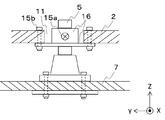
- FIG. 4 is a plan view showing the coupling structure of the mounting bracket 5 and the antenna adapter 2 when the inside of the radome 3 is viewed from above.
- FIG. 5 is an enlarged cross-sectional view of a part of the antenna device 100 along the PP'line of FIG.
- the mounting bracket 5 provided on the surface 7 of the moving body is coupled to the antenna adapter 2 via the bolt 15a and the receiving bracket 16. Therefore, the antenna adapter 2 can be easily removed from the moving body, and can be easily inspected or replaced at the time of failure.
- a receiving metal fitting 16 is attached to a part of the through hole 11 of the antenna adapter 2 by using a bolt 15b.
- the receiving metal fitting 16 and the mounting metal fitting 5 are connected by using a bolt 15a.
- a cushioning material 17 such as a rubber bush is interposed between the mounting bracket 5 and the receiving bracket 16, and even when the position of the mounting bracket 5 changes due to the pressurization inside the moving body. It plays a role in absorbing the stress caused by the change.
- Aircraft standards (ARINC791, ARINC792, etc.) stipulate that the antenna adapter 2 and the moving body surface 7 should be separated by 8 mm or more.
- the antenna device 100 When a moving object flies, the antenna device 100 also needs a structure to prepare for a lightning strike. Some of the surfaces of the radome 3 are provided with a structure for passing a current during a lightning strike, but if the distance between the inner wall of the radome 3 and the antenna element 13 is too narrow, dielectric breakdown due to electric discharge may occur. .. Therefore, it is preferable that the antenna adapter 2 and the moving body surface 7 have a gap of about 10 mm or more.
- the thickness of the antenna adapter 2 is preferably about 2 cm or less.
- the size of the antenna adapter 2 that is the base material of the antenna array 1 and the like varies depending on the size of the equipment to be mounted, but the size of the antenna for the Ka band defined by ARINC791 exceeds 2 square meters.
- the antenna array 1, the power supply 6, and the control circuit 8 installed in the antenna adapter 2 serve as heating elements.
- the antenna array 1 is the main heat source, and the communication IC 12 of the antenna array 1 needs to maintain the junction temperature at about 100 ° C. or lower. Therefore, in order for the antenna device 100 to operate, it is necessary to improve the heat dissipation performance of the antenna adapter 2 in which the communication IC 12 is installed.
- the running wind (outside air) obtained by the movement can be utilized for cooling the antenna device 100.
- the heating element is not set on the surface of the antenna device 100 in contact with the traveling wind, it is difficult to directly cool the antenna device 100 by the traveling wind. Therefore, in the antenna device 100 attached to the moving body, by providing a radiator in the peripheral portion of the antenna device 100, it is possible to dissipate heat from the radiator via the antenna adapter 2. As a result, the antenna device 100 can be cooled even if the heating element is not installed on the surface of the antenna device 100 in contact with the outside air.
- the radiator of the antenna device 100 is a smooth flat plate.
- the skirt 4 arranged around the antenna adapter 2 is used as a radiator. That is, the heat from the antenna adapter 2 is dissipated by the skirt 4.
- the skirt 4 is a flat metal plate, and there is a limit to the heat flux (the amount of heat that crosses the unit area per unit time) that can be obtained with the outside air. Therefore, in order to obtain high heat dissipation performance in the skirt 4, it is necessary to diffuse the heat transferred to the skirt 4 to the entire skirt 4 in advance.
- the heating element installed in the antenna device 100 diffuses heat to the skirt 4 via the antenna adapter 2. Therefore, by improving the ability of the antenna adapter 2 to diffuse heat, that is, the heat dissipation capacity of the antenna adapter 2, it is possible to diffuse the heat to the entire skirt 4 arranged along the outer periphery of the antenna adapter 2.
- the size of the antenna adapter 2 may be increased, but if the size of the antenna adapter 2 is restricted by aircraft standards or the like, the thickness of the antenna adapter 2 or It is difficult to increase the cross-sectional area, and there is a possibility that heat cannot be sufficiently diffused to the skirt 4.
- a communication IC 12 having a size of several tens of centimeters generates heat of a kilowatt class, sufficient heat diffusion may not be possible. If the heat cannot be sufficiently diffused to the skirt 4, the temperature of the central portion of the communication IC 12 cannot be lowered to 100 ° C. or lower, and the communication IC 12 may not operate as desired.
- the calorific value of the communication IC 12 is less than kilowatts, it is necessary to reduce the thermal resistance up to the skirt 4 which is the heat dissipation surface of the antenna adapter 2 having a thickness of about 2 cm as much as possible.
- the antenna adapter 2 As described above, most of the heat generated by the heating element of the antenna device 100 is transferred through the antenna adapter 2 and dissipated to the outside air using the skirt 4 as a heat radiating surface, but when the thickness of the antenna adapter 2 is thin. May not ensure sufficient heat dissipation.
- the antenna array 1 arranged in the central portion of the antenna adapter 2 has few effective heat dissipation paths because other heating elements are arranged around it, and heat is trapped.
- the antenna adapter 2 is provided with a heat pipe 9 having a high heat transport capacity.
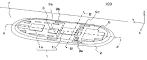
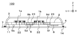
- FIG. 6 is a perspective view showing the antenna adapter 2 transmitted through the antenna device 100 shown in FIG. 7 is a cross-sectional view showing an AA'cross section of the antenna device 100 of FIG. 6, and FIG. 8 is a cross-sectional view showing a BB' cross section of the antenna device 100 of FIG.
- the control circuit 8, the power supply 6, and the antenna array 1 are connected by electrical wiring.
- the control circuit 8, the power supply 6, and the antenna array 1 are arranged on the opposite surfaces (+ Z-axis side surface and ⁇ Z-axis side surface) of the antenna adapter 2, the antenna array 1 of the antenna adapter 2 is arranged.
- a plurality of wiring through holes 22 connecting the + Z-axis side surface and the ⁇ Z-axis side surface for passing the electrical wiring are provided in the portion where the antennas are joined. Therefore, the heat pipes 9 (9a to 9d) are arranged in the antenna adapter 2 so as to surround the antenna array 1 so as not to interfere with the wiring through holes 22 (FIG. 6).
- the heat pipe 9 may be arranged only on one of the antenna arrays 1 having a high heat generation density.
- FIG. 6 shows an example in which the heat pipe 9 is arranged so as to sandwich the receiving antenna array 1b, but the arrangement example is not limited to this.
- the heat pipes 9 (9a to 9d) have a bent portion, and the shape thereof is L-shaped or the like.
- the heat pipes 9 (9a to 9d) need only be provided with a bent portion, and are not limited to the L-shape.
- the volatile working fluid is sealed in a pipe made of a material having high thermal conductivity such as copper and copper alloy, and the heat pipe 9 (9a to 9d) is operated by the heat of the heating element. It includes an evaporating unit 20 that vaporizes the fluid and a condensing unit 21 that condenses the vaporized working fluid.
- the working fluid becomes steam in the evaporation unit 20, moves to the condensation unit 21 and condenses, so that heat can be efficiently transferred.
- the condensed liquid is returned to the evaporation unit 20 again.
- the heat pipes 9 (9a to 9d) are arranged so as to extend from the antenna array 1 toward the skirt 4 so that the evaporation portion 20 of the heat pipe 9 faces the antenna array 1 side and the condensing portion 21 faces the skirt 4 side. ..
- the evaporation unit 20 faces the X-axis direction along the receiving antenna array 1b, and the condensing unit 21 that releases heat is located on the outer periphery of the antenna adapter 2. It is arranged so as to face the Y-axis direction along the adjacent skirt 4.
- the condensing portion 21 is arranged in a direction perpendicular to the traveling direction of the moving body, and the condensing portion 21 is arranged along the traveling direction of the moving body.
- the heat pipe 9a and the heat pipe 9b are arranged so that the condensing end of the heat pipe faces the + Y axis direction
- the heat pipe 9c and the heat pipe 9d are arranged so that the condensing end of the heat pipe faces the ⁇ Y axis direction.
- the condensing portion 21 is arranged in a direction parallel to the traveling direction of the moving body, or the condensing portion 21 is inclined from the traveling direction of the moving body. Including being placed in.
- the antenna device 100 should be low in the height direction in order to reduce air resistance, and it is desired that the antenna device 100 is lightweight.
- the antenna adapter 2 is required to have sufficient strength to withstand the lift received during flight. However, if the thickness of the antenna adapter 2 is about 2 cm, the heat pipe 9 (9a to 9d) is attached to the surface of the antenna adapter 2. It is also possible to place it in. However, considering that the communication radio wave between the antenna array 1 and the artificial satellite to be communicated is not blocked, and that the electrical wiring and insulation between the devices are not obstructed, the antenna adapter 2 should be arranged inside. Is desirable (FIGS. 7 and 8).
- FIG. 7 and 8 show an example in which the heat pipes 9 (9a to 9d) are arranged inside the antenna adapter 2 and within the thickness of the antenna adapter 2.
- the heat pipes 9 (9a to 9d) it is conceivable to provide the antenna adapter 2 with a groove 23 and install the heat pipe 9 (9a to 9d) along the groove 23.
- 9a-9d may be tilted and arranged.
- the end portion of the heat pipe 9a and the heat pipe 9b where the condensing portion 21 is located is tilted in the + Z direction until it fits within the thickness of the antenna adapter 2, and the evaporation portion of the heat pipe 9a and the heat pipe 9b. Tilt the portion where 20 is located in the ⁇ Z direction until it fits within the thickness of the antenna adapter 2.
- the end portion of the heat pipe 9c and the heat pipe 9d where the condensing portion 21 is located is tilted in the + Z direction until it fits within the thickness of the antenna adapter 2, and the portion where the evaporation portion 20 of the heat pipe 9a and the heat pipe 9b is located is tilted. Tilt in the ⁇ Z direction until it fits within the thickness of the antenna adapter 2 (Fig. 9). That is, the condensing portion 21 of the heat pipe 9 (9a to 9d) may be arranged so as to be above the evaporation portion 20.
- FIG. 6 shows an example in which the heat pipes 9 (9a to 9d) are arranged along the receiving antenna array 1b so that the thermal resistance between the heat pipes 9 (9a to 9d) and the receiving antenna array 1b is minimized. If the wiring through holes 22 are concentrated in the central portion of the receiving antenna array 1b, it is desirable to arrange the evaporation portion of the heat pipes 9 (9a to 9d) directly under the receiving antenna array 1b. ..
- the heat pipes 9 (9a to 9d) are arranged inside the antenna adapter 2 and directly below the antenna array 1.
- the heat pipes 9 (9a to 9d) are arranged in this way, the heat transport efficiency from the heating element can be improved, and the heat dissipation performance of the antenna adapter 2 can be improved.
- the improvement of the heat dissipation performance of the antenna adapter 2 it becomes possible to efficiently release heat to the outside by the skirt 4 which is the radiator of the antenna device 100.
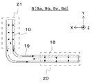
- FIG. 10 is a schematic cross-sectional view of the heat pipes 9 (9a to 9d).
- the structure of the heat pipe 9 and the cooling mechanism will be described with reference to FIG.
- the heat pipes 9a to 9d are distinguished in explaining the arrangement of the heat pipes 9, and are heat pipes 9 having the same structure as the heat pipes 9.
- the heat pipe 9 is a so-called wick type heat pipe 9, and a wick 10 is provided on the wall surface of the pipe.
- the wick 10 has a capillary structure, and the working fluid liquefied in the condensing unit 21 can be returned to the evaporation unit 20 by utilizing the capillary phenomenon of liquid.
- a working fluid is sealed inside the heat pipe 9.
- the larger the latent heat of vaporization the higher the heat transport capacity, so water is generally often used. However, water freezes below freezing. Therefore, when water is used as the working fluid, when the temperature of the heat pipe 9 becomes below the freezing point, the water may condense and expand, which may damage the heat pipe 9.
- the antenna device 100 When the antenna device 100 is mounted on an aircraft, it is exposed to the outside air of about 50 ° C. below freezing point in the sky. Therefore, if the antenna array 1 does not generate heat, the heat pipe 9 is cooled to below freezing point. There is also. Therefore, when water is used as the working fluid, a heating device such as a heater may be attached around the heat pipe 9. When the temperature of the environment in which the heat pipe 9 is used falls below the freezing point, a liquid containing ammonia, ethanol, or the like that does not freeze even below the freezing point may be used as the working fluid. That is, in the environment in which the antenna device 100 is used, a liquid that does not freeze may be used as the working fluid.
- the antenna device 100 attached to an aircraft it is predicted that it will be used in a low temperature environment during flight, so it is desirable to use a liquid that does not freeze under the usage environment as the working fluid of the heat pipe 9.
- the working fluid sealed inside the heat pipe 9 receives heat at the evaporation unit 20 and vaporizes. Since the pressure near the evaporation section 20 rises due to the vaporized working fluid 18, the vaporized working fluid 18 is carried to the condensing section 21 whose pressure is relatively low (broken arrow in FIG. 10).
- the condensing unit 21 is arranged closer to the outside air than the evaporation unit 20, and is cooled by the outside air. Therefore, the vaporized working fluid 18 (broken line arrow in FIG. 10) that has moved from the evaporation unit 20 is cooled and liquefied in the condensation unit 21.
- the working fluid 19 (solid arrow in FIG.
- liquefied in the condensing portion 21 is taken into the wick 10 arranged on the inner wall of the heat pipe 9.
- the liquefied working fluid 19 (solid arrow in FIG. 10) taken into the wick 10 is diffused by the capillary force of the wick 10 and is refluxed to the evaporating section 20 having a relatively lower capillary force than the condensing section 21.
- the liquefied working fluid 19 of the heat pipe 9 is vaporized in the evaporation section 20, carried to the condensation section 21, liquefied in the condensation section 21, and refluxed to the evaporation section 20 is called a reflux cycle. do.
- the heat pipe 9 can transport heat by utilizing the temperature around the heat pipe 9. Therefore, by using the heat pipe 9, heat can be transported without the need for a pump that requires maintenance.
- the heat pipe 9 is arranged so as to extend from the antenna array 1 toward the skirt 4. That is, the evaporation portion 20 of the heat pipe 9 is arranged near the antenna array 1 which is a heating element, and the condensing portion 21 of the heat pipe 9 is arranged near the skirt 4 which exchanges heat with the outside air.
- the working fluid of the heat pipe 9 receives heat from the antenna array 1, and the working fluid of the heat pipe 9 is vaporized.
- the vaporized working fluid 18 is carried to the condensing section 21 which is lower in temperature than the evaporating section 20, and is liquefied in the condensing section 21.
- the liquefied working fluid 19 returns to the evaporation section 20 by the capillary force of the wick 10 provided on the wall surface of the heat pipe 9.
- the heat pipe 9 carries the heat of the heating element from the central portion of the antenna adapter 2 to the outer peripheral portion where the skirt 4 is provided, which leads to improvement of the heat dissipation performance of the antenna adapter 2. That is, the heat diffusion efficiency of the antenna adapter 2 can be improved by providing the heat pipe 9.
- the heat pipe 9 is arranged along the groove 23 provided in the antenna adapter 2, the size of the antenna adapter 2 is not increased and the heating element is used. The heat can be dissipated toward the entire skirt 4.
- the heat of the antenna adapter 2 can be carried to the skirt 4 without increasing the size of the antenna adapter 2 and without maintenance. That is, by improving the heat dissipation performance of the antenna adapter 2, heat can be diffused to the entire skirt 4, and the cooling of the antenna device 100 is improved.
- the recirculation performance (wick limit) of the liquefied working fluid 19 due to the capillary force becomes a bottleneck.
- the maximum heat transport amount Q of the heat pipe 9 is represented by the equation (1).
- M is a term that depends on the characteristics of the working fluid, which is called the merit number.
- Right side second term is a term which depends on the wick properties, K is wick infiltration pressure coefficient, the r c a wick radius.
- the third term on the right side is a term that depends on the dimensions, A w is the cross-sectional area of the wick, and l eff is the effective length of the heat pipe 9.
- the fourth item is a term that depends on body force, where g is the gravitational acceleration, ⁇ is the surface tension, ⁇ l is the density, and ⁇ is the inclination of the heat pipe 9.
- the heat transport capacity is very high and the amount of latent heat is large when the recirculation cycle of the working fluid is operating.
- the thermal conductivity is one to two orders of magnitude higher.
- thermal conductivity performance higher than that of aluminum or copper, which is known as a good thermal conductor can be obtained.
- the equivalent thermal conductivity of the heat pipe 9 installed in the antenna device 100 is about 5000 W / mK
- the use of about four heat pipes 9 between the receiving antenna array 1b and the skirt 4 Thermal resistance can be reduced by about 30%. Therefore, when the air is generated in the kilowatt class, the temperature of the central portion of the receiving antenna array 1b can be kept below the target value even when the flight altitude of the aircraft is low and the outside air temperature is high.
- By increasing the number of heat pipes 9 arranged in the antenna adapter 2 to more than four it is possible to keep the temperature of the device lower.
- the installation space for the heat pipes 9 is limited, and the cost increases as the number of heat pipes 9 increases. Therefore, the maximum heat dissipation performance is achieved with the limited number of heat pipes 9. Is important.
- the recirculation cycle of the working fluid is delayed, and the liquefied working fluid 19 does not return to the evaporating part 20, that is, in a so-called dry-out state, the heat conduction is only the conduction of the pipe material of the heat pipe 9. ,
- the heat transport capacity may drop sharply.
- a factor that hinders the recirculation of the liquefied working fluid 19 is an event in which the body force (apparent weight) applied to the liquefied working fluid 19 cancels the capillary force.
- the antenna device 100 provided with the heat pipe 9 as shown in FIG. 6 is mounted on an aircraft. Since the satellite communication antenna of the aircraft is mainly used for in-flight entertainment, it is rarely used at the time of takeoff and landing, and it operates when cruising in the sky. Strictly speaking, the aircraft is flying with the nose raised about 3 degrees even when cruising in the sky, but for the sake of simplicity, it is assumed that the aircraft's fuselage is parallel to the XY plane (angle of attack 0 degrees). do. At this time, the direction of gravity when the aircraft is cruising (horizontal inertial flight) is considered to be the ⁇ Z axis direction.
- the liquefied working fluid 19 is not affected by body force as long as the heat pipes 9 (9a to 9d) are arranged in the XY plane, so that the liquefied working fluid is not affected. 19 is refluxed by capillary force. Therefore, all the heat pipes 9 (9a to 9d) can exhibit the expected heat transport capacity.
- the heat pipes 9 (9a to 9d) have a bent portion.
- the evaporation unit 20 is arranged so as to face the X-axis direction along the receiving antenna array 1b
- the condensing unit 21 is arranged so as to face the Y-axis direction along the skirt 4.
- the heat pipe 9a and the heat pipe 9b are arranged so that the evaporation portion 20 faces the X-axis direction and the condensing portion 21 faces the + Y-axis direction.
- the heat pipe 9c and the heat pipe 9d are arranged so that the evaporation portion 20 faces the X-axis direction and the condensing portion 21 faces the ⁇ Y-axis direction. That is, the condensing portion 21 of the heat pipe 9 (9a to 9d) is arranged in the direction (Y-axis direction) parallel to the traveling direction (+ Y-axis direction) of the moving body, and the evaporating portion 20 is arranged in the traveling direction (+ Y-axis direction) of the moving body. It is arranged in a direction (X-axis direction) perpendicular to (axial direction).
- At least one heat pipe 9 (9a, 9b) of the heat pipes 9 (9a to 9d) is provided so as to be bent in the same direction (+ Y-axis direction) as the traveling direction (+ Y-axis direction) of the moving body.
- At least one of the heat pipes 9 (9a to 9d) has a condensing portion 21, and the heat pipes 9 (9c, 9d) are in the direction opposite to the traveling direction (+ Y-axis direction) of the moving body (-Y-axis direction). ) Is bent and provided with a condensing portion 21.
- the heat pipes 9a and 9b correspond to the first heat pipe
- the heat pipes 9c and 9d correspond to the second heat pipe.
- the portion of the heat pipe 9 (9a to 9d) facing the Y-axis direction may be affected by the body force depending on the direction in which the acceleration is generated and the return direction of the working fluid.
- a portion arranged in a direction (Y-axis direction) parallel to the traveling direction (+ Y-axis direction) of the moving body may be affected by body force during acceleration. There is sex.
- the heat pipe 9c and the heat pipe 9d are temporarily prevented from recirculating by the body force, but in the heat pipe 9a and the heat pipe 9b, the recirculation is promoted by the body force, so that the heat pipe 9 (9a to 9d) as a whole is affected.
- the heat dissipation performance does not deteriorate.
- the antenna device 100 in which the heat pipes 9 (9a to 9d) are arranged as shown in FIG. 6, at least two heat pipes 9 continue to operate even when the moving body accelerates, so that the antenna device 100 is for reception.
- the antenna array 1b does not cause a sudden temperature rise that causes the junction temperature to exceed the specified value in a short time. That is, the heat pipe 9 does not dry out even during acceleration, and the heat of the antenna adapter 2 can continue to be dissipated to the skirt 4.
- the portion arranged in the direction (+ X-axis direction) perpendicular to the traveling direction (+ Y-axis direction) of the moving body is affected by the body force even during deceleration.
- the portion of the heat pipe 9 (9a to 9d) facing the Y-axis direction may be affected by the body force depending on the direction in which the acceleration is generated and the return direction of the working fluid.
- the heat pipe 99 (9a to 9d) having a bent portion a portion arranged in a direction (Y-axis direction) parallel to the traveling direction (+ Y-axis direction) of the moving body is affected by body force even during deceleration. there is a possibility.
- the heat pipe 9a and the heat pipe 9b are temporarily prevented from recirculating by the body force, but in the heat pipe 9c and the heat pipe 9d, the recirculation is promoted by the body force, so that the heat dissipation performance is not deteriorated.
- the heat pipes 9 (9a to 9d) are arranged as shown in FIG. 6, at least two heat pipes 9 continue to operate even when the moving body decelerates.
- the antenna array 1b does not cause a sudden temperature rise that causes the junction temperature to exceed the specified value in a short time. That is, the heat pipe 9 does not dry out even during deceleration, and the heat of the antenna adapter 2 can continue to be dissipated to the skirt 4.
- the antenna device 100 is thin by arranging the heat pipes 9 (9a to 9d) having the bent portion in the antenna adapter 2 extending from the antenna array 1 toward the skirt 4. Since the antenna device 100 does not require maintenance and the heat dissipation performance of the antenna adapter 2 can be improved, the antenna array 1 can be sufficiently cooled.
- the evaporating portion 20 of the heat pipes 9 (9a to 9d) faces the X-axis direction along the receiving antenna array 1b, and the condensing portion 21 faces the Y-axis direction along the skirt 4.
- the antenna adapter 2 Since it is not necessary to increase the size of the antenna adapter 2, it can also be applied to the thin antenna device 100. In addition, the antenna device 100 can be made thinner, the weight can be reduced, and the fuel efficiency of the moving body can be improved.
- the heat of the antenna adapter 2 can be efficiently transferred to the skirt 4 which is a radiator, heat can be dissipated even if the antenna array 1 or the like which is a heating element is installed in the center of the antenna adapter 2. Even if the communication capacity increases and the heat generation density increases at the center of the antenna adapter 2, the antenna array 1 can be cooled to the operating temperature, so that the antenna array 1 can be kept below the specified temperature. It will be possible.
- the antenna device can be configured according to the first embodiment.
- the cooling performance of 100 can be improved.
- the moving body when the moving body is an aircraft, situations such as cruising (horizontal inertial flight), acceleration and deceleration can be considered, but at least one end of the condensing portion 21 of the heat pipe 9 is oriented in the + Y axis direction, and at least one. Since the ends of the condensing portions 21 of the two heat pipes 9 are oriented in the ⁇ Y axis direction, the cooling performance of the antenna device 100 can be maintained. Further, even if the moving body accelerates or decelerates for a short time required for operation, all the heat pipes 9 mounted on the antenna device 100 do not dry out, and the antenna array 1 is kept below the specified temperature. It will be possible to keep. As a result, the cooling performance can be ensured even while the moving body is accelerating and decelerating, so that the communication service can be stably provided.
- FIG. 11 is a cross-sectional view of the antenna device 100 of the modified example of the antenna device 100 according to the first embodiment as viewed from the Z-axis direction.
- the modification of the present disclosure is a modification of the shape of the antenna adapter 2 and the shape of the heat pipes 9 (9a to 9d) according to the first embodiment.
- the shape of the antenna adapter 2 is an elliptical shape or an oval shape, and the bending of the heat pipes 9 (9a to 9d) is described by taking 90 degrees as an example.
- the antenna device 100 is mounted on a moving body having a fixed traveling direction such as an aircraft, in order to further reduce air resistance, for example, in the case of a drop-shaped shape in which the rear of the antenna adapter 2 is narrowed down. There is also.
- the condensing portion 21 side of the heat pipe 9 (9a to 9d) is arranged so as to be in contact with the skirt 4, the condensing portion 21 side of the heat pipe 9 (9a to 9d) does not follow the Y-axis direction.
- the bending of the heat pipe 9 is at an angle different from 90 degrees.
- at least one heat pipe 9 has the end of the condensing portion 21 facing the + Y axis direction, and at least one heat pipe 9 is a heat pipe.
- the antenna device 100 If the end of the condensing portion 21 of 9 is oriented in the ⁇ Y axis direction, the antenna device 100 according to the first embodiment even if the shape of the antenna adapter 2 of the first embodiment and the bending angle of the heat pipe 9 are different. The same effect as is obtained.
- the end of the condensing portion 21 of the heat pipe 9 is oriented in the + Y axis direction, and in the heat pipe 9c and the heat pipe 9d, the end of the condensing portion 21 of the heat pipe 9 is directed.
- the heat pipe 9a and the heat pipe 9b are condensed portions 21 of the heat pipe 9 when the length of the receiving antenna array 1b in the Y-axis direction is sufficiently long. The same effect can be obtained even if the end of the heat pipe 9c and the heat pipe 9d are arranged so that the end of the condensing portion 21 of the heat pipe 9 faces the + Y-axis direction.
- the number of heat pipes 9 has been described as four, the number of heat pipes 9 is increased if there is a margin in terms of cost, and if there is a margin in the installation space, it is mounted on the antenna adapter 2.
- the heat pipe 9 may be arranged around the transmission antenna array 1a, the control circuit 8, and the like.
- Embodiment 2 The antenna device 100 according to the second embodiment will be described with reference to FIGS. 12 and 13.
- the same reference numerals as those in FIGS. 6 and 10 indicate the same or corresponding parts.
- the heat pipe 9 of the antenna device 100 according to the first embodiment has two bent portions.
- the heat pipe 9 according to the second embodiment will be referred to as a U-shaped heat pipe. Further, the description of the content overlapping with the first embodiment will be omitted.
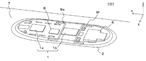
- FIG. 13 is a perspective view showing the arrangement of the U-shaped heat pipes 9 (9e, 9f) of the antenna device 101 according to the second embodiment.
- the arrangement of the U-shaped heat pipes 9 (9e, 9f) will be described with reference to FIG.
- the U-shaped heat pipes 9e and 9f have an evaporation unit 20 at the center of the heat pipe 9, and the evaporation unit 20 is arranged along the receiving antenna array 1b so as to face the X-axis direction. Further, the condensing portions 21a and 21b that release heat are arranged on the outer periphery of the antenna adapter 2 so as to face the Y-axis direction along the adjacent skirt 4.
- the condensing portions 21a and 21b of the heat pipes 9 (9e, 9f) are arranged in a direction (Y-axis direction) parallel to the traveling direction (+ Y-axis direction) of the moving body, and the evaporating portion 20 is in the traveling direction of the moving body. It is arranged in a direction (X-axis direction) perpendicular to (+ Y-axis direction). Further, at least one heat pipe 9 (9e) of the heat pipes 9 (9e, 9f) is provided by bending in the same direction (+ Y-axis direction) as the traveling direction (+ Y-axis direction) of the moving body.
- the heat pipes 9 (9f) having parts 21a and 21b and at least one of the heat pipes 9 (9e, 9f) are in the direction opposite to the traveling direction (+ Y-axis direction) (-Y-axis direction) of the moving body. It has a condensed portion 21 provided by bending.
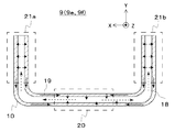
- FIG. 13 is a cross-sectional view of the U-shaped heat pipe 9 (9e, 9f) of the antenna device 101 according to the second embodiment.
- the structure of the U-shaped heat pipe 9 (9e, 9f) and the cooling mechanism will be described with reference to FIG.
- the heat pipe 9e and the heat pipe 9f are distinguished in explaining the arrangement of the U-shaped heat pipe 9, and are heat pipes having the same structure as the heat pipe 9.
- the U-shaped heat pipe 9 (9e, 9f) has two bent portions, has an evaporation portion 20 in the central portion, and has condensing portions 21a and 21b on both end portions.
- the U-shaped heat pipe 9 (9e, 9f) has a shape in which the ends of the evaporation portions 20 of the two L-shaped heat pipes 9 (FIG. 6) are joined. Therefore, the U-shaped heat pipe 9 (9e, 9f) has a configuration different from that of the L-shaped heat pipe 9 in that it has two bent portions, but other structures are the same as those of the L-shaped heat pipe 9.
- the working fluid sealed inside the U-shaped heat pipe 9 (9e, 9f) is vaporized by receiving heat from the receiving antenna array 1b at the evaporation unit 20 provided in the central portion. Since the pressure near the evaporation part 20 rises due to the vaporized working fluid 18, the vaporized working fluid 18 moves separately to the condensing parts 21a and 21b of the U-shaped heat pipe 9 (9e, 9f) having a relatively low pressure. (Dashed arrow in FIG. 13). Since the condensing portions 21a and 21b are arranged on the outer periphery of the antenna adapter 2 along the skirt 4 arranged adjacent to the antenna adapter 2, they are cooled by the running wind. Therefore, the vaporized working fluid 18 (broken line arrow in FIG.
- the U-shaped heat pipe 9 (9e, 9f) can transport heat by utilizing the ambient temperature of the U-shaped heat pipe 9 (9e, 9f). Therefore, by using the U-shaped heat pipes 9 (9e, 9f), it is possible to transport heat without the need for a pump that requires maintenance.
- the moving body is an aircraft, tilt the body when turning to obtain a bank angle.
- the apparent weight body force
- the apparent weight is generated in the -Z axis direction, so that it affects the capillary force of the liquefied working fluid 19. No volumetric force is generated.
- the heat dissipation performance is not deteriorated even when acceleration is generated in the X-axis direction.
- the condensing portions 21a and 21b are oriented in the + Y-axis direction, when acceleration is applied in the + Y-axis direction (during deceleration), the capillary force of the liquefied working fluid 19 is canceled by the body force. Therefore, the return to the evaporation unit 20 is temporarily prevented.
- the U-shaped heat pipe 9f arranged in pairs with the U-shaped heat pipe 9e since the condensing portions 21a and 21b are oriented in the ⁇ Y axis direction, acceleration is applied in the + Y axis direction (during deceleration). ), Since the body force generated in the liquefied working fluid 19 acts in the direction of promoting the recirculation, the heat transport capacity is improved as compared with the case where the body force is not generated.
- the U-shaped heat pipes 9e and 9f are arranged so that the condensing portions 21 of the U-shaped heat pipes 9e and 9f are arranged in the traveling direction of the moving body, and the condensing portions 21 of at least one heat pipe 9 are arranged in the same direction as the traveling direction of the moving body.
- the antenna device 101 shown in the second embodiment not only obtains the same effect as the antenna device 100 according to the first embodiment, but also uses more heat pipes 9 than the antenna device 100 shown in the first embodiment. Therefore, the weight of the antenna device 101 can be reduced. By reducing the weight of the antenna device 101, it is possible to reduce the fuel consumption of the moving body on which the antenna device 101 is mounted.
- At least one heat pipe 9 can operate without any problem even when the moving body accelerates and decelerates, the time required for the antenna element 13 used in the antenna device 101 to exceed the specified temperature is lengthened. This makes it possible to prolong the usable state of the antenna device 101.
- the ends of the condensing portions 21a and 21b of the U-shaped heat pipe 9e are oriented in the + Y-axis direction, and the ends of the condensing portions 21a and 21b of the U-shaped heat pipe 9f are oriented in the ⁇ Y-axis direction.
- the ends of the condensing portions 21a and 21b of the U-shaped heat pipe 9e are arranged in the ⁇ Y axis direction and the ends of the condensing portions 21a and 21b of the U-shaped heat pipe 9f are arranged in the + Y axis direction.
- the same effect as that of the first and second embodiments of the above can be obtained.
- Embodiment 3 The antenna device 102 according to the third embodiment will be described with reference to FIGS. 14 and 15.
- the same reference numerals as those in FIGS. 6 and 10 indicate the same or corresponding parts.
- the antenna device 102 of the third embodiment has a different arrangement of the heat pipes 9 (9 g, 9 h) from the antenna device 101 according to the second embodiment. Further, the description of the contents overlapping with the first embodiment and the second embodiment will be omitted.
- FIG. 14 is a perspective view showing the arrangement of U-shaped heat pipes (9 g, 9 h) of the antenna device 102 according to the third embodiment.
- the arrangement of the U-shaped heat pipe 9 (9 g, 9 h) will be described with reference to FIG.
- the evaporation sections 20a and 20b of the U-shaped heat pipe 9 (9g, 9h) are located at both ends of the heat pipe 9, and the evaporation sections 20a and 20b are arranged near the receiving antenna array 1b which is a heating element. That is, the heat pipes 9 have evaporation portions 20a and 20b on both ends, and the evaporation portions 20a and 20b are arranged so as to be along the receiving antenna array 1b so as to face the X-axis direction.
- the heat-dissipating condensing portions 21 are arranged on the outer periphery of the antenna adapter 2 so as to face the Y-axis direction along the adjacent skirts 4.
- the antenna adapter 2 in the portion where the antenna array 1 is arranged is provided with a plurality of wiring through holes 22 connecting the + Z-axis side surface and the ⁇ Z-axis side surface of the antenna adapter 2 in order to pass electrical wiring.
- the heat pipes 9e and 9f are arranged along the receiving antenna array 1b so that the thermal resistance between the heat pipes 9e and 9f is minimized, but the wiring through hole 22 is tentatively received.
- the heat pipes 9g and 9h are concentrated in the central portion of the antenna array 1b, the evaporative portions of the heat pipes 9g and 9h should be arranged directly below the receiving antenna array 1b.
- FIG. 15 is a cross-sectional view of a U-shaped heat pipe 9 (9 g, 9 h) of the antenna device 102 according to the third embodiment.
- the structure and cooling mechanism of the U-shaped heat pipe 9 (9 g, 9 h) will be described with reference to FIG.
- the heat pipe 9g and the heat pipe 9h are distinguished for explaining the arrangement of the U-shaped heat pipe 9, and are heat pipes having the same structure as the heat pipe 9.
- the U-shaped heat pipe 9 (9 g, 9h) has the same basic structure as the U-shaped heat pipe 9 (9e, 9f) of the second embodiment. However, the difference is that the condensing portion 21 is located at the center of the U-shaped heat pipe 9, and the evaporation portions 20a and 20b are located on both ends of the U-shaped heat pipe 9.
- the working fluid sealed inside the U-shaped heat pipe 9 (9 g, 9 h) is vaporized by receiving heat from the receiving antenna array 1b at the evaporation portions 20a and 20b provided on both end sides. Since the pressure near the evaporation parts 20a and 20b rises due to the vaporized working fluid 18, the vaporized working fluid 18 gathers in the condensing part 21 of the U-shaped heat pipe 9 (9g, 9h) having a relatively low pressure. (Dashed arrow in FIG. 15). Since the condensing portion 21 is arranged on the outer periphery of the antenna adapter 2 along the skirt 4 arranged adjacent to the antenna adapter 2, it is cooled by the running wind. Therefore, the vaporized working fluid 18 (broken line arrow in FIG.
- the working fluid 19 liquefied in the condensing portion 21 (solid arrow in FIG. 15) is taken into the wick 10 arranged on the inner wall of the U-shaped heat pipe 9 (9 g, 9 h).
- the liquefied working fluid 19 (solid arrow in FIG. 15) taken into the wick 10 is diffused by the capillary force of the wick 10 and flows to the evaporating portions 20a and 20b whose capillary pressure is relatively lower than that of the condensing portion 21.
- the heat pipe 9 can transport heat by utilizing the temperature around the heat pipe 9. Therefore, by using the heat pipe 9, heat can be transported without the need for a pump that requires maintenance.
- the antenna device 102 shown in the third embodiment not only obtains the same effect as the antenna device 100 according to the first embodiment, but also when the receiving antenna array 1b, which is the main cooling target, is long in the Y-axis direction. Especially effective.
- an appropriate region width is required for the condensing portion 21 of the heat pipe 9, and for example, about 1/3 to 1/4 of the total length of the heat pipe 9 is appropriate.
- the transmitting antenna array is tentatively arranged. If a heat radiating means such as a heat pipe is separately provided for cooling 1a or the control circuit 8, there is a possibility of spatial interference.
- an L-shaped heat pipe 9 is considered in combination with the U-shaped heat pipe 9 (9 g, 9h).
- the condensing portion 21 of the heat pipe 9 arranged on the + Y-axis side of the receiving antenna array 1b is bent toward the ⁇ Y-axis side, and the condensing portion 21 of the heat pipe 9 arranged on the ⁇ Y-axis side of the receiving antenna array 1b is bent.
- the weight of the antenna device 102 can be reduced.
- the L-shaped heat pipe 9 (9a to 9d) having one bend in the heat pipe 9 has been described, but the condensing portion 21 of the L-shaped heat pipe 9 is used. It may be combined and composed of a U-shaped heat pipe 9 (9 g, 9 h). That is, it has a heat pipe 9 (9a to 9d) having a condensing portion bent in the same direction as the traveling direction of the moving body and a condensing portion provided bent in the direction opposite to the traveling direction of the moving body.
- a heat pipe 9 (9 g, 9 h) configured by connecting the heat pipe 9 (9a to 9d) may be used.
- 1 Antenna array 1a Transmission antenna array, 1b Reception antenna array, 2 Antenna adapter, 3 Redome, 4 Skirt, 5, 5a, 5b, 5c, 5d, 5e, 5f Mounting bracket, 6 Power supply, 7 Moving object surface, 8 control circuit, 9 heat pipe, 9a, 9b, 9c, 9d L-shaped heat pipe, 9e, 9f, 9g, 9h U-shaped heat pipe, 10 wick, 11 through hole, 12 communication IC, 13 antenna element, 14 elastic body, 15a, 15b bolt, 16 receiving metal fitting, 17 cushioning material, 18 vaporized working fluid, 19 liquefied working fluid, 20 evaporating part, 21 condensing part, 22 wiring through hole, 23 groove, 100, 101, 102 Antenna device.
Landscapes
- Engineering & Computer Science (AREA)
- Mechanical Engineering (AREA)
- Details Of Aerials (AREA)
- Variable-Direction Aerials And Aerial Arrays (AREA)
Priority Applications (3)
| Application Number | Priority Date | Filing Date | Title |
|---|---|---|---|
| JP2022508669A JP7317211B2 (ja) | 2020-03-17 | 2020-03-17 | アンテナ装置 |
| PCT/JP2020/011768 WO2021186568A1 (ja) | 2020-03-17 | 2020-03-17 | アンテナ装置 |
| US17/908,915 US12034206B2 (en) | 2020-03-17 | 2020-03-17 | Antenna device |
Applications Claiming Priority (1)
| Application Number | Priority Date | Filing Date | Title |
|---|---|---|---|
| PCT/JP2020/011768 WO2021186568A1 (ja) | 2020-03-17 | 2020-03-17 | アンテナ装置 |
Publications (1)
| Publication Number | Publication Date |
|---|---|
| WO2021186568A1 true WO2021186568A1 (ja) | 2021-09-23 |
Family
ID=77770990
Family Applications (1)
| Application Number | Title | Priority Date | Filing Date |
|---|---|---|---|
| PCT/JP2020/011768 Ceased WO2021186568A1 (ja) | 2020-03-17 | 2020-03-17 | アンテナ装置 |
Country Status (3)
| Country | Link |
|---|---|
| US (1) | US12034206B2 (https=) |
| JP (1) | JP7317211B2 (https=) |
| WO (1) | WO2021186568A1 (https=) |
Families Citing this family (4)
| Publication number | Priority date | Publication date | Assignee | Title |
|---|---|---|---|---|
| US20220354020A1 (en) * | 2019-09-06 | 2022-11-03 | Carlisle Interconnect Technologies, Inc. | Mounting System For Mounting An Element To An Aircraft Surface |
| US12218400B2 (en) * | 2021-12-28 | 2025-02-04 | Mitsubishi Electric Corporation | Antenna device |
| CN118073810B (zh) * | 2024-04-25 | 2024-06-25 | 成都飞翼通科技有限公司 | 一种用于天线散热的整流罩结构 |
| CN118676602A (zh) * | 2024-08-07 | 2024-09-20 | 人天通信集团有限公司 | 一种方柱型天线美化外罩 |
Citations (3)
| Publication number | Priority date | Publication date | Assignee | Title |
|---|---|---|---|---|
| WO2017081148A1 (en) * | 2015-11-12 | 2017-05-18 | Connaught Electronics Ltd. | Sharkfin rf and camera integration |
| JP2019198009A (ja) * | 2018-05-10 | 2019-11-14 | 三菱電機株式会社 | アンテナ装置 |
| WO2020004274A1 (ja) * | 2018-06-26 | 2020-01-02 | 京セラ株式会社 | アンテナ素子、アレイアンテナ、通信ユニット、移動体、および基地局 |
Family Cites Families (3)
| Publication number | Priority date | Publication date | Assignee | Title |
|---|---|---|---|---|
| JP2003298270A (ja) * | 2002-03-29 | 2003-10-17 | Mitsubishi Electric Corp | アンテナ装置 |
| JP4564483B2 (ja) | 2006-12-27 | 2010-10-20 | 株式会社東芝 | 面型アクティブフェーズドアレイアンテナ装置 |
| JP6904243B2 (ja) | 2017-12-27 | 2021-07-14 | 三菱電機株式会社 | 移動体用アンテナ装置 |
-
2020
- 2020-03-17 US US17/908,915 patent/US12034206B2/en active Active
- 2020-03-17 WO PCT/JP2020/011768 patent/WO2021186568A1/ja not_active Ceased
- 2020-03-17 JP JP2022508669A patent/JP7317211B2/ja active Active
Patent Citations (3)
| Publication number | Priority date | Publication date | Assignee | Title |
|---|---|---|---|---|
| WO2017081148A1 (en) * | 2015-11-12 | 2017-05-18 | Connaught Electronics Ltd. | Sharkfin rf and camera integration |
| JP2019198009A (ja) * | 2018-05-10 | 2019-11-14 | 三菱電機株式会社 | アンテナ装置 |
| WO2020004274A1 (ja) * | 2018-06-26 | 2020-01-02 | 京セラ株式会社 | アンテナ素子、アレイアンテナ、通信ユニット、移動体、および基地局 |
Also Published As
| Publication number | Publication date |
|---|---|
| US12034206B2 (en) | 2024-07-09 |
| US20230087437A1 (en) | 2023-03-23 |
| JPWO2021186568A1 (https=) | 2021-09-23 |
| JP7317211B2 (ja) | 2023-07-28 |
Similar Documents
| Publication | Publication Date | Title |
|---|---|---|
| WO2021186568A1 (ja) | アンテナ装置 | |
| JP7050958B2 (ja) | アンテナ装置 | |
| US9293802B2 (en) | Antenna tile device and cold plate | |
| JP7119228B2 (ja) | アンテナ装置 | |
| US7940524B2 (en) | Remote cooling of a phased array antenna | |
| JP6999489B2 (ja) | アンテナ装置 | |
| US9578781B2 (en) | Heat management for electronic enclosures | |
| US10703490B2 (en) | Method and apparatus for heat-dissipation in electronics | |
| KR102380996B1 (ko) | 냉각홀이 형성된 항공기용 레이돔 어셈블리 | |
| CN113782940B (zh) | 高速气流穿通式风冷散热机载天线 | |
| CN109511253A (zh) | 一种有源相控阵雷达组件散热控温技术 | |
| CN209710577U (zh) | 一种有源相控阵雷达组件散热结构 | |
| US12245407B2 (en) | Aircraft and method for thermal management | |
| US12218400B2 (en) | Antenna device | |
| JP3539274B2 (ja) | アンテナ装置の冷却構造 | |
| CN113206369A (zh) | 用于飞行器的天线组件及飞行器 | |
| CN112492849A (zh) | 轻质高导热板 | |
| CN116946395B (zh) | 磁浮平台卫星载荷拓展散热面控温装置 | |
| US20250031346A1 (en) | Systems and methods for thermal management of externally mounted electronic equipment for an aircraft | |
| CN114620215A (zh) | 无人机机头及无人机 | |
| JP2019140429A (ja) | パラボラアンテナ装置の導風装置、パラボラアンテナ装置およびパラボラアンテナ装置の冷却方法 | |
| KR20250045378A (ko) | 잠열을 이용한 전자 소자 냉각장치 | |
| CN117734984A (zh) | 电调散热整流装置及飞行器 | |
| CN120370339A (zh) | 面向无人机的微型测风雷达温控系统及方法 | |
| JP2005059770A (ja) | 通気ダクト |
Legal Events
| Date | Code | Title | Description |
|---|---|---|---|
| 121 | Ep: the epo has been informed by wipo that ep was designated in this application |
Ref document number: 20925546 Country of ref document: EP Kind code of ref document: A1 |
|
| ENP | Entry into the national phase |
Ref document number: 2022508669 Country of ref document: JP Kind code of ref document: A |
|
| NENP | Non-entry into the national phase |
Ref country code: DE |
|
| 122 | Ep: pct application non-entry in european phase |
Ref document number: 20925546 Country of ref document: EP Kind code of ref document: A1 |