WO2021186549A1 - 冷凍空調装置 - Google Patents
冷凍空調装置 Download PDFInfo
- Publication number
- WO2021186549A1 WO2021186549A1 PCT/JP2020/011708 JP2020011708W WO2021186549A1 WO 2021186549 A1 WO2021186549 A1 WO 2021186549A1 JP 2020011708 W JP2020011708 W JP 2020011708W WO 2021186549 A1 WO2021186549 A1 WO 2021186549A1
- Authority
- WO
- WIPO (PCT)
- Prior art keywords
- refrigerant
- refrigerating
- air
- fluorescent agent
- window portion
- Prior art date
- Legal status (The legal status is an assumption and is not a legal conclusion. Google has not performed a legal analysis and makes no representation as to the accuracy of the status listed.)
- Ceased
Links
Images




Classifications
-
- F—MECHANICAL ENGINEERING; LIGHTING; HEATING; WEAPONS; BLASTING
- F25—REFRIGERATION OR COOLING; COMBINED HEATING AND REFRIGERATION SYSTEMS; HEAT PUMP SYSTEMS; MANUFACTURE OR STORAGE OF ICE; LIQUEFACTION SOLIDIFICATION OF GASES
- F25B—REFRIGERATION MACHINES, PLANTS OR SYSTEMS; COMBINED HEATING AND REFRIGERATION SYSTEMS; HEAT PUMP SYSTEMS
- F25B49/00—Arrangement or mounting of control or safety devices
- F25B49/02—Arrangement or mounting of control or safety devices for compression type machines, plants or systems
Definitions
- This disclosure relates to a freezing air conditioner.
- the refrigerating and air-conditioning system is provided with a refrigerant circuit (refrigerant cycle) in which a compressor, a condenser, an expansion valve and an evaporator are sequentially connected, and the refrigerant circulates in the refrigerant circuit.
- a refrigerant circuit refrigerant cycle
- work is performed to identify the location where the refrigerant is leaking.
- Non-Patent Document 1 As one method of identifying the location where the refrigerant is leaking, there is a method of spraying a foaming agent (Non-Patent Document 1). In this method, the location where the refrigerant is leaking is identified by spraying the foaming agent on the portion where the refrigerant is suspected to be leaking. When the foaming agent is sprayed on the part where the refrigerant is leaking, bubbles are generated at that part.
- Non-Patent Document 2 As another method for identifying the location where the refrigerant is leaking, there is a method using a refrigerant gas detector (Non-Patent Document 2). In this method, the refrigerant gas detector is applied to the refrigerant pipe (circuit) to identify the location where the refrigerant is leaking.
- Patent Document 1 As yet another method for identifying the location where the refrigerant is leaking, there is a method using a fluorescent agent (Patent Document 1).
- a fluorescent agent for detecting refrigerant leakage is added to refrigerating machine oil that circulates together with the refrigerant in the refrigeration circuit, and ultraviolet rays are irradiated by an ultraviolet lamp to identify the location where the refrigerant is leaking.
- the fluorescent agent leaked together with the refrigerant and the refrigerating machine oil emits light by irradiation with ultraviolet rays.
- the method for identifying the location where the refrigerant is leaking using a fluorescent agent circulates together with the refrigerant in order to reliably identify the location where the refrigerant is leaking. It is necessary to control the concentration of the fluorescent agent added to the refrigerating machine oil.
- the present disclosure was made as part of such development, and an object thereof is to provide a refrigerating air conditioner capable of easily confirming the concentration of the fluorescent agent added to the refrigerating machine oil.
- the refrigerating and air-conditioning apparatus is a refrigerating and air-conditioning apparatus having a refrigerating cycle in which a compressor, a condenser, an expansion valve and an evaporator are connected in order by a refrigerant pipe, and is a refrigerant, a refrigerating machine oil, a fluorescent agent, and a window. And have. Refrigerant and refrigerating machine oil circulate in the refrigeration cycle.
- the fluorescent agent is added to the refrigerating machine oil that circulates with the refrigerant.
- the window is provided in the refrigeration cycle to check the condition in the refrigeration cycle.
- the refrigerating cycle is provided with a window for checking the state in the refrigerating cycle.
- the window is irradiated with ultraviolet rays, and the emission intensity of the fluorescent agent added to the refrigerating machine oil is measured with respect to the intensity of the ultraviolet rays, so that the fluorescent agent having an appropriate concentration is added. It is possible to judge whether or not.
- a fluorescent agent having an appropriate concentration to the refrigerating machine oil, it is possible to reliably observe the fluorescence emitted by irradiating with ultraviolet rays. As a result, the location where the refrigerant is leaking can be reliably identified.
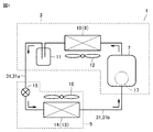
- FIG. It is a figure which shows the refrigerating cycle of the refrigerating air-conditioning apparatus which concerns on each embodiment. It is a figure which shows the refrigerating cycle of the refrigerating air-conditioning apparatus which concerns on Embodiment 1.
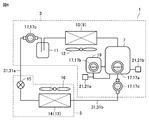
- FIG. It is a figure which shows the refrigerating cycle of the refrigerating air-conditioning apparatus which concerns on Embodiment 2. It is a figure which shows the refrigerating cycle of the refrigerating air-conditioning apparatus which concerns on Embodiment 3. It is a figure which shows the refrigerating cycle of the refrigerating air-conditioning apparatus which concerns on Embodiment 4. It is a figure which shows the refrigerating cycle of the refrigerating air-conditioning apparatus which concerns on Embodiment 5.
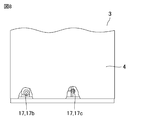
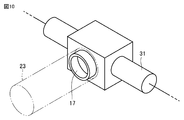
- FIG. 1 it is a diagram showing a refrigeration cycle including a desirable arrangement of windows and supply ports. It is a partial front view which shows the structure of the outdoor unit for demonstrating the desirable arrangement of the window part in each embodiment. In each embodiment, it is a front view of the outdoor unit for explaining the structure of the housing with respect to the window part shown in FIG. In each embodiment, it is a partial perspective view of the refrigerant pipe which shows the state which attached the cylindrical body to the window part.
- the refrigerating and air-conditioning device 1 includes an outdoor unit 3 and an indoor unit 5.
- the outdoor unit 3 houses a compressor 7, a heat exchanger 10 that serves as a condenser 9 (or an evaporator), and a liquid reservoir 11.
- the indoor unit 5 houses an expansion valve 15 and a heat exchanger 14 that serves as an evaporator 13 (or a condenser).
- the compressor 7, the heat exchanger 10, the liquid reservoir 11, the expansion valve 15, and the heat exchanger 14 are connected in this order by the refrigerant pipe 31.
- the outdoor unit 3 and the indoor unit 5 are connected by a local liquid pipe 31a and a local gas pipe 31b as a part of the refrigerant pipe 31.
- the refrigerant flows from the outdoor unit 3 to the indoor unit 5 the refrigerant flows through the local liquid pipe 31a.
- the refrigerant flows from the indoor unit 5 to the outdoor unit 3, the refrigerant flows through the local gas pipe 31b.
- the compressor 7 is a fluid machine that compresses the sucked low-pressure refrigerant and discharges it as a high-pressure refrigerant.
- the rotation frequency may be controlled by an inverter.
- the compressor 7 may be a compressor that rotates at a constant rotation speed.
- the heat exchanger 10 When the heat exchanger 10 functions as the condenser 9, the heat exchanger 10 exchanges heat between the refrigerant discharged from the compressor 7 and the outside air such as outdoor air. By this heat exchange, heat is released from the refrigerant to the outside air. Further, the heat exchanger 10 (condenser 9) may be a heat exchanger (condenser) that releases the heat of the refrigerant to the outside air sent by the fan 12.
- the expansion valve 15 expands the refrigerant flowing from the condenser 9 through the local liquid pipe 31a to reduce the pressure.
- the expansion valve 15 for example, an electronic expansion valve, a mechanical temperature type automatic expansion valve, a capillary, or the like can be used.
- the heat exchanger 14 When the heat exchanger 14 functions as the evaporator 13, heat exchange is performed in the heat exchanger 14 between the refrigerant decompressed by the expansion valve 15 and indoor air such as air in the freezing chamber. .. By this heat exchange, heat is released from the indoor air to the refrigerant, and the indoor air is cooled. Further, the heat exchanger 14 (evaporator 13) may be a heat exchanger (evaporator) that releases the heat of the outside air sent by the fan 16 to the refrigerant.
- a high-temperature and high-pressure gas refrigerant is discharged from the compressor 7.
- the discharged high-temperature and high-pressure gas refrigerant flows into the heat exchanger 10.
- the heat exchanger 10 functions as a condenser 9. In the heat exchanger 10, heat exchange is performed between the flowing refrigerant and the air supplied by the fan 12.
- the high-temperature and high-pressure gas refrigerant condenses into a high-pressure liquid refrigerant (single-phase).
- the high-pressure liquid refrigerant sent out from the heat exchanger 10 is sent to the indoor unit 5 via the liquid reservoir 11 and flows through the expansion valve 15.
- the high-pressure liquid refrigerant becomes a two-phase refrigerant of a low-pressure gas refrigerant and a liquid refrigerant by the expansion valve 15.
- the two-phase refrigerant flows into the heat exchanger 14.
- heat exchanger 14 heat exchange is performed between the flowing two-phase refrigerant and the air supplied by the fan 16.
- the liquid refrigerant evaporates to become a low-pressure gas refrigerant (single-phase). This heat exchange cools the room.
- the low-pressure gas refrigerant sent out from the heat exchanger 14 flows into the compressor 7.
- the low-pressure gas refrigerant that has flowed into the compressor 7 is compressed to become a high-temperature and high-pressure gas refrigerant, and is discharged from the compressor 7 again.
- this cycle is repeated.
- the flow of the refrigerant is in the opposite direction to the above-mentioned flow.
- the refrigerant will circulate in the refrigeration cycle along with the refrigerating machine oil and fluorescent agent.
- a single refrigerant, a pseudo-azeotropic mixed refrigerant, a non-quasi-azeotropic mixed refrigerant, or the like is used as the refrigerant that circulates in the refrigerating cycle (refrigerant circuit).
- the single refrigerant includes, for example, R22 or R134a.
- Examples of the pseudo azeotropic mixed refrigerant include R410A and R404A.
- the non-quasi-azeotropic mixed refrigerant include R407C and the like.
- a fluorescent agent for detecting the leakage of the refrigerant from the refrigerant pipe 31 and the like is added to the refrigerating machine oil that circulates in the refrigerating cycle together with the refrigerant. It is necessary to control the concentration of the fluorescent agent added to the refrigerating machine oil in order to reliably identify the location where the refrigerant is leaking.
- the above-mentioned refrigerating and air-conditioning device 1 is formed with a window portion 17 for checking the state in the refrigerating cycle.
- a sight glass is attached to the window portion 17.
- the concentration of the fluorescent agent added to the refrigerating machine oil can be estimated by irradiating the window portion 17 with ultraviolet rays and measuring the emission intensity of the fluorescent agent with respect to the intensity of the ultraviolet rays.
- the amount of the fluorescent agent added is, for example, about 0.25% by weight with respect to the refrigerating machine oil.
- Embodiment 1 An example of the refrigerating and air-conditioning apparatus 1 according to the first embodiment will be described.
- the compressor 7 is provided with the window portion 17a as the window portion 17 for confirming the state in the refrigeration cycle.
- the window portion 17a is provided, for example, at a height (position) where the oil level in the vicinity of the oil pool in the compressor 7 can be confirmed.
- ultraviolet rays emitted from an ultraviolet lamp are irradiated toward the window portion 17a provided in the compressor 7.
- the emission intensity of fluorescence emitted from a fluorescent agent by irradiating with ultraviolet rays is measured.
- concentration of the fluorescent agent added to the refrigerating machine oil is within an appropriate range.
- amount of the fluorescent agent added is about 0.25% by weight with respect to the refrigerating machine oil.
- the refrigerating machine oil to which the fluorescent agent is added leaks together with the refrigerant at the place where the refrigerant leaks.
- a fluorescent agent having an appropriate concentration (addition amount) to the refrigerating machine oil, it is possible to reliably observe the fluorescence emitted by irradiating with ultraviolet rays. As a result, the location where the refrigerant is leaking can be reliably identified.
- Embodiment 2 An example of the refrigerating and air-conditioning apparatus 1 according to the second embodiment will be described.
- an oil regulator 19 for storing refrigerating machine oil supplied in the refrigerating cycle is connected to the compressor 7.
- the oil regulator 19 is provided with a window portion 17b for checking the state in the refrigeration cycle.
- FIG. 3 shows a refrigeration cycle in which the compressor 7 is also provided with the window portion 17a, a refrigeration cycle in which the compressor 7 is not provided with the window portion 17a may be used.
- the emission intensity of fluorescence emitted from the fluorescent agent is measured by irradiating the window portion 17b provided in the oil regulator 19 with ultraviolet rays. By comparing the emission intensity with the reference emission intensity, it is determined whether or not the concentration of the fluorescent agent added to the refrigerating machine oil is within an appropriate range.
- the refrigerating machine oil to which the fluorescent agent is added leaks together with the refrigerant at the place where the refrigerant leaks.
- a fluorescent agent having an appropriate concentration (addition amount) to the refrigerating machine oil, it is possible to reliably observe the fluorescence emitted by irradiating with ultraviolet rays. As a result, the location where the refrigerant is leaking can be reliably identified.
- Embodiment 3 An example of the refrigerating and air-conditioning apparatus 1 according to the third embodiment will be described.
- the refrigerant pipe 31 between the liquid reservoir 11 and the indoor unit 5 arranged in the outdoor unit 3 is provided with a window portion 17c for checking the state in the refrigeration cycle.
- the window portion 17c is the condenser 9 (heat exchanger 9). 10)
- it is arranged on the downstream side of the flow of the refrigerant, and is arranged on the outlet side of the outdoor unit 3 in the refrigerant pipe 31.
- FIG. 4 shows a refrigeration cycle in which the compressor 7 is provided with the window portion 17a and the oil regulator 19 is provided with the window portion 17b.
- the window portion 17 may be a refrigeration cycle device in which both the window portion 17a and the window portion 17b are not provided. Further, a refrigeration cycle may be used in which the window portion 17 of either the window portion 17a or the window portion 17b is not provided.
- the emission intensity of fluorescence emitted from the fluorescent agent is measured by irradiating the window portion 17c provided on the outlet side of the outdoor unit 3 with ultraviolet rays. By comparing the emission intensity with the reference emission intensity, it is determined whether or not the concentration of the fluorescent agent added to the refrigerating machine oil is within an appropriate range.
- the refrigerating machine oil to which the fluorescent agent is added leaks together with the refrigerant at the place where the refrigerant leaks.
- a fluorescent agent having an appropriate concentration (addition amount) to the refrigerating machine oil, it is possible to reliably observe the fluorescence emitted by irradiating with ultraviolet rays. As a result, the location where the refrigerant is leaking can be reliably identified.
- Embodiment 4 An example of the refrigerating and air-conditioning apparatus 1 according to the fourth embodiment will be described.
- a window portion 17d for checking the inside of the refrigeration cycle is provided on the upstream side of the flow of the refrigerant with respect to the compressor 7.
- the window portion 17d is the outdoor unit 3 in the refrigerant pipe 31. It will be located on the entrance side of.
- FIG. 5 shows a refrigeration cycle in which the compressor 7 is provided with the window portion 17a, the oil regulator 19 is provided with the window portion 17b, and the window portion 17c is provided on the outlet side of the outdoor unit.
- the window portion 17 may be a refrigeration cycle device in which all of the window portion 17a, the window portion 17b, and the window portion 17c are not provided. Further, a refrigeration cycle in which any two window portions 17 of the window portion 17a, the window portion 17b, and the window portion 17c are not provided may be used. Further, a refrigeration cycle may be used in which the window portion 17 of any one of the window portion 17a, the window portion 17b and the window portion 17c is not provided.
- the emission intensity of fluorescence emitted from the fluorescent agent is measured by irradiating the window portion 17d provided on the inlet side of the outdoor unit 3 with ultraviolet rays. By comparing the emission intensity with the reference emission intensity, it is determined whether or not the concentration of the fluorescent agent added to the refrigerating machine oil is within an appropriate range.
- the refrigerating machine oil to which the fluorescent agent is added leaks together with the refrigerant at the place where the refrigerant leaks.
- a fluorescent agent having an appropriate concentration (addition amount) to the refrigerating machine oil, it is possible to reliably observe the fluorescence emitted by irradiating with ultraviolet rays. As a result, the location where the refrigerant is leaking can be reliably identified.
- the window portion 17d is arranged on the suction side of the compressor 7, it can be confirmed that the fluorescent agent circulates in the refrigerating cycle.
- Embodiment 5 An example of the refrigerating and air-conditioning apparatus 1 according to the fifth embodiment will be described.
- the outdoor unit 3 for example, two supply ports 21 for supplying the fluorescent agent to be added to the refrigerating machine oil into the refrigerating cycle are provided.
- the oil regulator 19 is provided with the supply port 21a
- the compressor 7 is provided with the supply port 21b.
- the emission intensity of fluorescence emitted from the fluorescent agent is measured by irradiating the window portion 17a provided in the compressor 7 or the like with ultraviolet rays. By comparing the emission intensity with the reference emission intensity, it is determined whether or not the concentration of the fluorescent agent added to the refrigerating machine oil is within an appropriate range.
- the fluorescent agent is supplied into the refrigeration cycle from the supply port 21a or the supply port 21b. If the emission intensity of the fluorescence emitted from the window 17 by irradiating with ultraviolet rays falls within an appropriate range, the supply of the fluorescent agent may be stopped.
- the inventors have conducted various studies on the position of the window portion 17 and the position of the fluorescent agent supply port 21 from the viewpoints of ease of work such as irradiation of ultraviolet rays, measurement of fluorescence, and supply of fluorescent agent, cost, and the like. rice field. As a result, as shown in FIG. 7, it was determined that it is preferable that the window portion 17 is provided with the window portion 17b in the oil regulator 19 and the window portion 17c is provided on the outlet side of the outdoor unit 3. Further, as the supply port 21, it was determined that it is preferable to provide the supply port 21a in the oil regulator 19.
- the oil regulator 19 is a tank for storing refrigerating machine oil. Inside the tank, a supply pipe for supplying refrigerating machine oil, a float as a member for adjusting the oil level of the refrigerating machine oil, and an adjusting mechanism for adjusting the amount of refrigerating machine oil supplied by opening and closing the supply pipe by floating are arranged. There is. As a result, a desired amount of refrigerating machine oil is stored in the tank.
- a sight glass of the window portion 17 is provided on either one of the oil regulator 19 and the compressor 7. Just do it. Considering the formability (ease of manufacture) and the point of confirming whether or not the fluorescent agent could be supplied from the fluorescent agent supply port 21, the sight glass of the window portion 17b was placed in the tank of the oil regulator 19 and the oil level was increased. It is considered more preferable to arrange the position so that the can be seen. By arranging the window portion 17a in the compressor 7, the position of the oil level of the refrigerating machine oil can be confirmed more accurately.
- Embodiment 6 An example of the refrigerating and air-conditioning apparatus 1 according to the sixth embodiment will be described.
- the emission intensity of fluorescence emitted from the fluorescent agent is measured by irradiating the window portion 17 with ultraviolet rays. At this time, it is easier to capture the fluorescence emitted from the fluorescent agent in a place where the surroundings are dark than in a place where the surroundings are bright.
- the position of the window portion 17 is preferably a position where sunlight does not directly enter. Therefore, as shown in FIG. 8, it is preferable that the window portion 17 is arranged in, for example, the housing 4 of the outdoor unit 3. In FIG. 8, for example, a window portion 17b provided in the oil regulator and a window portion 17c provided on the outlet side of the outdoor unit 3 are shown.
- the sight glasses of the windows 17b and 17c are also used during maintenance. Therefore, it is desirable that the windows 17b and 17c are arranged in a position inside the housing 4 where maintenance is easy. For example, it is desirable to arrange the windows 17b and 17c in a position where the maintenance sheet metal (door) can be opened and immediately confirmed. ..
- the housing 4 is provided with an opening 4b facing the window 17c and an opening 4a facing the window 17b.
- the concentration of the fluorescent agent can be measured more accurately without opening the door or the like. be able to.
- a tubular body 23 may be arranged in the window portion 17 to darken the periphery of the window portion 17. .. By arranging the tubular body 23, the concentration of the fluorescent agent can be measured more accurately.
- the fluorescent agent that circulates in the refrigeration cycle may solidify and precipitate when the temperature of the refrigerating machine oil drops.
- the fluorescent agent may precipitate when the evaporation temperature of the refrigerant is low (for example, ⁇ 45 ° C.).
- the refrigerating machine oil does not contain the fluorescent agent, or the amount of the fluorescent agent contained in the refrigerating machine oil decreases.
- the liquid back phenomenon is, for example, when heat exchange is not performed well due to frosting of the evaporator or a drastic decrease in air volume, the refrigerant is sucked into the compressor in a two-phase state of liquid and gas. The phenomenon that is done.
- the location where the refrigerant is leaking in the refrigeration cycle by the light emission of the fluorescent agent may be difficult to identify the location where the refrigerant is leaking in the refrigeration cycle by the light emission of the fluorescent agent. Therefore, when it is determined that the refrigerant is leaking, liquid backing occurs immediately before that, and precipitation of the fluorescent agent is confirmed, the temperature of the refrigerant is raised to eliminate the precipitation of the fluorescent agent.
- the irradiation of the fluorescent agent with ultraviolet rays and the measurement of the fluorescence emitted from the fluorescent agent may be performed by an operator, or may be measured by using a sensor or the like for measuring the fluorescence intensity. May be good.
- the heat exchanger 10 of the outdoor unit 3 functions as a condenser and the heat exchanger 14 of the indoor unit 5 functions as an evaporator
- the heat exchanger 10 of the outdoor unit 3 may function as an evaporator
- the heat exchanger 14 of the indoor unit 5 may function as a condenser.
- the position where the window portion is provided may be appropriately changed as necessary. Even in such a case, the concentration of the fluorescent agent can be measured.
- This disclosure is effectively used in a freezing air conditioner equipped with a freezing cycle in which a refrigerant circulates.
- Refrigerating air conditioner 3 Outdoor unit, 4 Housing, 4a, 4b opening, 5 Indoor unit, 7 Compressor, 9 Condenser, 10 Heat exchanger, 11 Liquid reservoir, 12 Fan, 13 Evaporator, 14 Heat exchange Vessel, 15 expansion valve, 16 fan, 17, 17a, 17b, 17c, 17d window, 19 oil regulator, 21, 21a, 21b supply port, 23 tubular body, 31 refrigerant pipe, 31a local liquid pipe, 31b local gas Plumbing.
Landscapes
- Engineering & Computer Science (AREA)
- Physics & Mathematics (AREA)
- Mechanical Engineering (AREA)
- Thermal Sciences (AREA)
- General Engineering & Computer Science (AREA)
- Other Air-Conditioning Systems (AREA)
- Investigating, Analyzing Materials By Fluorescence Or Luminescence (AREA)
Priority Applications (3)
| Application Number | Priority Date | Filing Date | Title |
|---|---|---|---|
| JP2022508654A JP7357763B2 (ja) | 2020-03-17 | 2020-03-17 | 冷凍空調装置 |
| PCT/JP2020/011708 WO2021186549A1 (ja) | 2020-03-17 | 2020-03-17 | 冷凍空調装置 |
| CN202080098342.5A CN115280083A (zh) | 2020-03-17 | 2020-03-17 | 制冷空调装置 |
Applications Claiming Priority (1)
| Application Number | Priority Date | Filing Date | Title |
|---|---|---|---|
| PCT/JP2020/011708 WO2021186549A1 (ja) | 2020-03-17 | 2020-03-17 | 冷凍空調装置 |
Publications (1)
| Publication Number | Publication Date |
|---|---|
| WO2021186549A1 true WO2021186549A1 (ja) | 2021-09-23 |
Family
ID=77770910
Family Applications (1)
| Application Number | Title | Priority Date | Filing Date |
|---|---|---|---|
| PCT/JP2020/011708 Ceased WO2021186549A1 (ja) | 2020-03-17 | 2020-03-17 | 冷凍空調装置 |
Country Status (3)
| Country | Link |
|---|---|
| JP (1) | JP7357763B2 (https=) |
| CN (1) | CN115280083A (https=) |
| WO (1) | WO2021186549A1 (https=) |
Cited By (2)
| Publication number | Priority date | Publication date | Assignee | Title |
|---|---|---|---|---|
| WO2023084771A1 (ja) * | 2021-11-15 | 2023-05-19 | 三菱電機株式会社 | アキュムレータおよび冷凍サイクル装置 |
| WO2025004228A1 (ja) * | 2023-06-28 | 2025-01-02 | 三菱電機株式会社 | 冷凍装置および空気調和装置 |
Citations (6)
| Publication number | Priority date | Publication date | Assignee | Title |
|---|---|---|---|---|
| JPS58221353A (ja) * | 1982-06-17 | 1983-12-23 | 三菱電機株式会社 | 冷凍装置の油供給装置 |
| JPH10288430A (ja) * | 1997-04-10 | 1998-10-27 | Denso Corp | 流量検出装置 |
| JP2003215040A (ja) * | 2002-01-24 | 2003-07-30 | Daikin Ind Ltd | 冷凍サイクルにおける潤滑油の状態検出装置 |
| JP2006275325A (ja) * | 2005-03-28 | 2006-10-12 | Sanyo Electric Co Ltd | コンプレッサユニット |
| JP2010078292A (ja) * | 2008-09-29 | 2010-04-08 | Chino Corp | オイル循環率測定装置 |
| WO2018225263A1 (ja) * | 2017-06-09 | 2018-12-13 | 三菱電機株式会社 | 冷凍装置および空気調和装置 |
Family Cites Families (1)
| Publication number | Priority date | Publication date | Assignee | Title |
|---|---|---|---|---|
| JP6818474B2 (ja) * | 2016-09-09 | 2021-01-20 | 三菱電機株式会社 | 冷凍サイクル装置 |
-
2020
- 2020-03-17 CN CN202080098342.5A patent/CN115280083A/zh active Pending
- 2020-03-17 WO PCT/JP2020/011708 patent/WO2021186549A1/ja not_active Ceased
- 2020-03-17 JP JP2022508654A patent/JP7357763B2/ja active Active
Patent Citations (6)
| Publication number | Priority date | Publication date | Assignee | Title |
|---|---|---|---|---|
| JPS58221353A (ja) * | 1982-06-17 | 1983-12-23 | 三菱電機株式会社 | 冷凍装置の油供給装置 |
| JPH10288430A (ja) * | 1997-04-10 | 1998-10-27 | Denso Corp | 流量検出装置 |
| JP2003215040A (ja) * | 2002-01-24 | 2003-07-30 | Daikin Ind Ltd | 冷凍サイクルにおける潤滑油の状態検出装置 |
| JP2006275325A (ja) * | 2005-03-28 | 2006-10-12 | Sanyo Electric Co Ltd | コンプレッサユニット |
| JP2010078292A (ja) * | 2008-09-29 | 2010-04-08 | Chino Corp | オイル循環率測定装置 |
| WO2018225263A1 (ja) * | 2017-06-09 | 2018-12-13 | 三菱電機株式会社 | 冷凍装置および空気調和装置 |
Cited By (4)
| Publication number | Priority date | Publication date | Assignee | Title |
|---|---|---|---|---|
| WO2023084771A1 (ja) * | 2021-11-15 | 2023-05-19 | 三菱電機株式会社 | アキュムレータおよび冷凍サイクル装置 |
| JP7646020B2 (ja) | 2021-11-15 | 2025-03-14 | 三菱電機株式会社 | アキュムレータおよび冷凍サイクル装置 |
| WO2025004228A1 (ja) * | 2023-06-28 | 2025-01-02 | 三菱電機株式会社 | 冷凍装置および空気調和装置 |
| WO2025004772A1 (ja) * | 2023-06-28 | 2025-01-02 | 三菱電機株式会社 | 冷凍装置および空気調和装置 |
Also Published As
| Publication number | Publication date |
|---|---|
| JP7357763B2 (ja) | 2023-10-06 |
| CN115280083A (zh) | 2022-11-01 |
| JPWO2021186549A1 (https=) | 2021-09-23 |
Similar Documents
| Publication | Publication Date | Title |
|---|---|---|
| ES2743328T3 (es) | Sistema de aire acondicionado | |
| JP6929747B2 (ja) | 空気調和機 | |
| CN110050160B (zh) | 热泵装置 | |
| CN104603557B (zh) | 制冷装置 | |
| JP6750696B2 (ja) | 冷媒サイクル装置 | |
| CN111201411A (zh) | 制冷装置 | |
| CN107429957A (zh) | 制冷循环装置以及制冷循环系统 | |
| ES2967966T3 (es) | Dispositivo de ciclo de refrigerante | |
| CN110709650B (zh) | 热泵利用设备 | |
| JP7357763B2 (ja) | 冷凍空調装置 | |
| WO2018011994A1 (ja) | 空気調和装置 | |
| WO2015132959A1 (ja) | 空気調和装置 | |
| JP6498289B2 (ja) | 冷凍サイクルシステム | |
| JP7412887B2 (ja) | 空気調和機及び流路切換弁 | |
| AU2010364874B2 (en) | Part replacement method for refrigeration cycle device and refrigeration cycle device | |
| CN110785617B (zh) | 空调装置 | |
| JP2016223640A (ja) | 冷凍空調装置 | |
| CN112752936B (zh) | 制冷剂填充方法 | |
| CN114364932A (zh) | 压缩机单元及冷冻装置 | |
| EP3591311A1 (en) | Refrigeration cycle device | |
| US20180259220A1 (en) | Corrosion inhibitor module for a packaged terminal air conditioner unit | |
| CN117063032A (zh) | 空调机 | |
| CN105308395B (zh) | 冷冻装置 | |
| KR20210109844A (ko) | 공기 조화 장치 및 그의 물 충전 방법 | |
| KR20090103416A (ko) | 공기조화 시스템 |
Legal Events
| Date | Code | Title | Description |
|---|---|---|---|
| 121 | Ep: the epo has been informed by wipo that ep was designated in this application |
Ref document number: 20926214 Country of ref document: EP Kind code of ref document: A1 |
|
| ENP | Entry into the national phase |
Ref document number: 2022508654 Country of ref document: JP Kind code of ref document: A |
|
| NENP | Non-entry into the national phase |
Ref country code: DE |
|
| 122 | Ep: pct application non-entry in european phase |
Ref document number: 20926214 Country of ref document: EP Kind code of ref document: A1 |