WO2021186526A1 - 回転電機 - Google Patents
回転電機 Download PDFInfo
- Publication number
- WO2021186526A1 WO2021186526A1 PCT/JP2020/011615 JP2020011615W WO2021186526A1 WO 2021186526 A1 WO2021186526 A1 WO 2021186526A1 JP 2020011615 W JP2020011615 W JP 2020011615W WO 2021186526 A1 WO2021186526 A1 WO 2021186526A1
- Authority
- WO
- WIPO (PCT)
- Prior art keywords
- partition plate
- electric machine
- rotary electric
- dividing
- divided
- Prior art date
- Legal status (The legal status is an assumption and is not a legal conclusion. Google has not performed a legal analysis and makes no representation as to the accuracy of the status listed.)
- Ceased
Links
Images





Classifications
-
- H—ELECTRICITY
- H02—GENERATION; CONVERSION OR DISTRIBUTION OF ELECTRIC POWER
- H02K—DYNAMO-ELECTRIC MACHINES
- H02K9/00—Arrangements for cooling or ventilating
- H02K9/02—Arrangements for cooling or ventilating by ambient air flowing through the machine
- H02K9/04—Arrangements for cooling or ventilating by ambient air flowing through the machine having means for generating a flow of cooling medium
- H02K9/06—Arrangements for cooling or ventilating by ambient air flowing through the machine having means for generating a flow of cooling medium with fans or impellers driven by the machine shaft
-
- H—ELECTRICITY
- H02—GENERATION; CONVERSION OR DISTRIBUTION OF ELECTRIC POWER
- H02K—DYNAMO-ELECTRIC MACHINES
- H02K9/00—Arrangements for cooling or ventilating
- H02K9/19—Arrangements for cooling or ventilating for machines with closed casing and closed-circuit cooling using a liquid cooling medium, e.g. oil
Definitions
- This application relates to a rotary electric machine.
- a refrigerant flow path is formed using a partition plate that partitions the internal space of the rotary electric machine in order to allow the refrigerant that cools the internal components of the rotary electric machine to flow.
- the partition plate is made of FRP (Fiber Reinforced Plastics) material, is formed in a shape surrounding the rotation axis, and is configured by connecting members divided into two in the circumferential direction (see, for example, Patent Document 1). .. Further, it is disclosed that the partition plate is made of a metal material (see, for example, Patent Document 2). Further, it is disclosed that the partition plate having a shape surrounding the rotating shaft is configured by a connectable split structure (see, for example, Patent Document 3).
- Cited Document 1 discloses an example in which the partition plate provided inside the rotary electric machine is formed of an FRP material which is an insulating member and has a further divided structure.
- an edge portion extending from the surface portion constituting the refrigerant flow path is required, two of the edge portions are overlapped, and the overlapped edge portion is used as a fastening material. It was configured to be connected by fixing it. If a metal bolt is used as the fastening material, it becomes necessary to secure an insulation distance between the bolt and the conductive portion of the component, which hinders the miniaturization of the rotary electric machine. Further, by providing the partition plate with an edge portion required for bolt fastening, the size of the partition plate itself becomes large, which also hinders the miniaturization of the rotary electric machine.
- Cited Document 2 since the partition plate is made of metal, it is necessary to keep an insulating distance between the coil end and the partition plate, and as a result, there is a problem that the total length of the rotary electric machine becomes large. Further, in Cited Document 3, detailed contents regarding the fact that the partition plate has a connectable split structure are not disclosed, and the specific configuration is unknown.
- This application was made to solve the above problems, and aims at further miniaturization of the rotary electric machine.
- the rotary electric machine includes a cylindrical stator arranged inside the frame, a rotor arranged on the inner peripheral side of the stator supported by a rotating shaft, and fixed to the rotating shaft in the axial direction.
- a partition that blows refrigerant into the machine along the machine, is arranged outside the stator inside the frame in the axial direction, and extends radially outward from the intake portion around the rotation shaft to form a refrigerant flow path.
- the partition plate is provided with a plate, the partition plate is formed of an insulating member, and a plurality of partition plate divided bodies divided in the circumferential direction are abutted and joined at the divided surface, and the partition plate divided bodies adjacent to each other are formed on the divided surface.
- Each groove is formed to form a communicating hole, and a coupling made of an insulating member is arranged in the hole across both of the two partition plate dividers. ..
- the entire partition plate can be composed of an insulating member without increasing the thickness of the partition plate, and the effect peculiar to the present application of miniaturization of the rotary electric machine can be obtained.
- FIG. It is a side sectional view of the rotary electric machine according to Embodiment 1.
- FIG. It is a top view of the partition plate of the rotary electric machine of Embodiment 1.
- FIG. It is a top view which shows one of the partition plate divisions constituting the partition plate of FIG.
- FIG. It is a side view which shows the state which the coupling body is inserted into the groove part of the division surface of the partition plate division body of Embodiment 1.
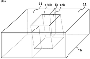
- FIG. It is an enlarged perspective view of the main part of the partition plate of Embodiment 1.
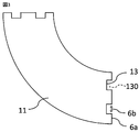
- FIG. FIG. 5 is an enlarged plan view of a main part of the partition plate divided body of the second embodiment. It is a top view of the partition plate of Embodiment 2.
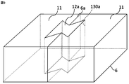
- FIG. 5 is an enlarged perspective view of a main part of the partition plate of the second embodiment.
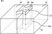
- FIG. 5 is an enlarged perspective view of a main part of the partition plate of the third embodiment.
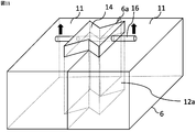
- FIG. 5 is an enlarged perspective view of a main part showing a state in which the coupling body is removed from the partition plate of FIG.
- FIG. 5 is an enlarged perspective view of the groove part of the division surface of the partition plate division body of Embodiment 5.
- FIG. 5 is an enlarged perspective view of a main part of the partition plate of the fifth embodiment.
- FIG. 1 is a side sectional view taken along the axis of the rotary electric machine 100 according to the first embodiment.
- the rotary electric machine 100 includes a frame 1, a stator 2, a rotor 3, a bracket 4, a rotary shaft 5, a partition plate 6, a fan 7 (axial flow fan), a coil end 8, and a heat exchanger 9. Etc. are provided as the main components.
- the cylindrical stator 2 is fixed inside the frame 1, and the rotor 3 integrated with the rotating shaft 5 is rotatably supported on the inner peripheral side of the stator 2.
- Brackets 4 which are annular members, are provided at both ends of the frame 1 in the axial direction to seal the internal space of the rotary electric machine 100.
- the rotating shaft 5 extends outward from both ends of the rotor 3 in the axial direction and engages with the bracket 4.
- the rotating shaft 5 is provided with a fan 7 that blows the refrigerant 10 inside the machine along the axial direction inside the frame 1.
- the heat exchanger 9 is arranged on the upper part of the frame 1, and the refrigerant 10 cooled by the heat exchanger 9 (the direction in which the refrigerant flows is indicated by an arrow) is placed inside the frame 1 at both ends in the axial direction. It passes through the refrigerant flow path consisting of the space partitioned by the partition plate 6, and is sent by the fan 7 to the inside of the machine, that is, to the side of the rotor 3, the stator 2, and the coil end 8 to cool each member and to the outside in the radial direction. It flows and is returned to the heat exchanger 9 again.
- the partition plate 6 is arranged outside the stator 2 inside the frame 1 in the axial direction, and extends radially outward from the intake portion around the rotating shaft 5 to form a refrigerant flow path.
- the partition plate 6 is made of an insulating member, for example, made of glass fiber reinforced plastic (FRP).
- FIG. 2 is a plan view of the partition plate 6 forming the refrigerant flow path inside the rotary electric machine 100, and shows a plan shape perpendicular to the axis.
- the partition plate 6 is formed in a ring shape having an opening for passing the rotating shaft 5 in the central portion thereof, and the opening serves as an intake portion for sending the refrigerant 10 to the inside of the machine in the axial direction.
- the partition plate division 11 formed by dividing into four equal parts in the circumferential direction is connected by the coupling body 12, and the partition plate 6 integrated is shown.
- the partition plate 6 is fixed to the inside of the rotary electric machine 100 by connecting the outer peripheral side thereof to the frame 1.
- the partition plate 6 has a configuration in which a plurality of partition plate divided bodies 11 are connected in the circumferential direction.
- the end face in the circumferential direction of one partition plate dividing body 11 is the dividing surface 6a.
- the dividing surface 6a is formed so as to extend radially from the rotating shaft 5.
- the number of divisions of the partition plate 6 can be adjusted as appropriate, and in addition to dividing the partition plate 6 at equal intervals, adjustments such as dividing one into a semicircle and the other into smaller parts are also possible. Needless to say.
- the dividing surface 6a of the partition plate dividing body 11 can be provided in a different direction in addition to the surface portion extending radially from the rotating shaft 5, and can be provided from the rotating shaft 5 during manufacturing or maintenance of the rotary electric machine 100.
- the extending direction of the dividing surface 6a can be adjusted so that the partition plate 6 can be easily removed.
- the opening shape of the intake portion located at the inner peripheral portion of the partition plate 6 can be formed in a funnel shape having a curved surface portion smoothly inclined in the axial direction as illustrated in FIG.
- the coupling body 12 is fitted into the abutting surface portion where the dividing surfaces 6a of the adjacent partition plate dividing bodies 11 are butted against each other, and the coupling body 12 and the partition plate dividing body 11 are combined with each other. It is a configuration in which the partition plate divided bodies 11 are connected to each other by the frictional force of the above.
- the connecting bodies 12 are arranged at two separated positions in one dividing surface 6a. Needless to say, the number and arrangement of the twelve can be adjusted as appropriate.
- FIG. 3 is an enlarged plan view of one partition plate dividing body 11, and the groove portion 13 formed on the dividing surface 6a which is the end surface in the circumferential direction is opened so that the plane shape becomes a quadrangle, and the dividing surface 6a is formed.
- the opening 6b opened in the above is dug down to a predetermined depth perpendicular to the dividing surface 6a, and the planar shape shown in FIG. 3 is provided in a shape swept in the axial direction.
- the groove portion 13 constitutes a part of the hole portion 130 into which the coupling body 12 is inserted.
- a hole 130 formed by communicating the two groove portions 13 is formed on the dividing surface 6a.
- the opening shape formed in one surface side of the partition plate 6 (machine outer surface portion 11a described later) extends to the other surface side of the partition plate 6 (machine inner surface portion 11b described later).
- the shape is swept in the direction, and in the example of the first embodiment, the hole 130 is provided in the axial direction.
- FIG. 4 is a side view showing a state in which the coupling body 12 is inserted into the groove portion 13 of the dividing surface 6a of the partition plate dividing body 11, from the machine outer surface portion 11a which is one plane of the partition plate dividing body 11.
- the conjugate 12 is inserted.
- the opening portion 6b of the groove portion 13 is opened on the dividing surface 6a of the partition plate dividing body 11. Since the shapes of the dividing surfaces 6a of the two partition plate dividing bodies 11 are provided symmetrically, the respective partition plates are in a state of being butted so that the divided surfaces 6a completely overlap each other.
- the opening 6b of the divided body 11 becomes a common opening region and forms one hole 130.
- One coupling body 12 is inserted into one hole 130, and the coupling body 12 is hung and arranged between adjacent partition plate split bodies 11, and the coupling body 12 plays a role as a connecting member. ..
- the shape of the groove portion 13 provided in the two adjacent partition plate divided bodies 11 may be the same shape as described above, or may be a different shape.
- the length (axis direction dimension) of the partition plate dividing body 11 of the coupling body 12 to be inserted into the hole 130 is equal to the thickness of the partition plate dividing body 11, the surface portion of the partition plate 6 is formed. Since no unevenness is generated, air resistance can be reduced, the constituent materials can be reduced when the conjugate 12 is shorter, and when the conjugate 12 is longer, the protrusion is processed into a projecting portion protruding from the surface portion. It is possible to additionally form an engaging portion or the like that can be used at the time of assembly.
- the composite body 12 is composed of an insulating member, and may be made of the same material as the partition plate 6 or may be made of a different material.
- FIG. 5 is an enlarged perspective view of a main part of the partition plate 6 when the axis is in the vertical direction, and shows a state in which the two partition plate dividing bodies 11 are connected via one coupling body 12.
- the combined body 12 is formed in a columnar shape and is fitted between the adjacent partition plate divided bodies 11.
- the partition plate dividing body 11 and the coupling body 12 are combined. 12 may be adhered with an adhesive.
- the partition plate 6 has a configuration in which the partition plate divided bodies 11 divided into a plurality of parts in the circumferential direction are abutted at the divided surface 6a which is the end surface thereof and are connected to each other.
- One hole 130 is formed by communicating the groove 13 formed in each of the split surfaces 6a of the adjacent partition plate splits 11, and the coupling body 12 made of an insulating member is inserted into the hole 130 without a gap. ..
- the bond 12 is formed in a shape that fills the hole 130.
- the joint is arranged across both of the two partition plate divisions 11, and the partition plate division 11 and the joint 12 are joined to form a partition plate 6 made of a ring-shaped insulating member as a whole. ..
- the partition plate 6 has a role of forming a flow path for sending the refrigerant 10 blown by the fan 7 from the outside of the partition plate 6 to the inside of the machine.
- an external force typified by an electromagnetic excitation force induced by the rotation of the rotor 3 acts on the partition plate 6 with the operation of the rotary electric machine 100
- the adjacent partition plate dividers 11 are separated from each other and the partition plates are separated from each other. If a gap is formed between the divided bodies 11, the refrigerant 10 may flow out from the inside of the machine to the outside of the machine through the gap, and a desired cooling effect may not be obtained. Therefore, it is necessary to suppress the separation of the adjacent partition plate dividing bodies 11 from each other and to join the partition plate dividing bodies 11 to each other so that a gap does not occur in the partition plate 6.
- the normal vector in the direction toward the inside of the hole 130 formed by the groove 13 on all the surfaces (inner wall surface and bottom surface) constituting the groove 13 is the radial direction and the partition plate division. It has an outward component of body 11.
- this normal vector has no component in the direction from the dividing surface 6a toward the inside of the partition plate dividing body 11, the partition plate dividing bodies 11 are separated from each other in the direction perpendicular to the dividing surface 6a.
- an external force acts on the partition plate 6, the frictional force generated between the partition plate dividing body 11 and the coupling body 12 acts as a force to prevent the partition plate dividing bodies 11 from being separated from each other.
- a groove portion 13 is formed along the axis on the dividing surface 6a of the partition plate dividing body 11, and the coupling body 12 is inserted into the groove portion 13. Therefore, even if an external force is generated in the radial direction of the partition plate 6, the coupling body 12 is arranged so as to extend in the axial direction across the two partition plate dividing bodies 11, so that the coupling is formed on the dividing surface 6a. The rotation around the body 12 can be suppressed, and the deviation can be prevented.
- the coupling body 12 and the partition plate dividing body 11 can be combined by forming the structure in which the coupling body 12 is arranged.
- the joint area of the joint body 12 can be increased more than the area of the division surface 6a when the joint body 12 is not provided, and the frictional force between the joint body 12 and the partition plate divided body 11 can be increased. It is possible to prevent the plate split bodies 11 from being separated from each other and to suppress the formation of gaps.
- the partition plate dividing body 11 is formed without using metal bolts and without providing the edge portion of the partition plate for bolt fastening. 11 can be combined with each other. Further, since the partition plate dividing body 11 and the coupling body 12 are formed by an insulating member, the coil end 8 and the partition plate 6 which are indispensable in the structure of a rotary electric machine using a metal bolt as a conventional fastening material.
- the axial dimension of the partition plate 6 itself does not increase, and the rotary electric machine 100
- the total length can be shortened as compared with the conventional one, and the device can be miniaturized.
- FIG. 2 an example in which the plane shape perpendicular to the axis is square is illustrated in FIG. 2 and the like, but when a force is applied in a direction in which the two abutted dividing surfaces 6a are separated from each other, a force is applied.
- a means such as adhesion with an adhesive as described above. According to this configuration, it goes without saying that the surface area serving as the adhesive surface is increased by providing the groove portion 13 on the divided surface 6a, and the adhesive performance is improved.
- the number of the groove portion 13 and the coupling body 12 formed on one dividing surface 6a of the partition plate dividing body 11 is not limited to two, and can be one or three or more. Needless to say, it can be changed according to the shape of the partition plate 6 to be formed (outer shape such as radial dimension and axial thickness).
- Embodiment 2 the rotary electric machine 100 according to the second embodiment of the present application will be described with reference to FIGS. 6 to 9.
- a hole 130 is provided in which the groove 13 provided in the two partition plate dividing bodies 11 is communicated with each other at the abutting surface, and the coupling 12 is provided in the hole 130.
- the opening dimension of the opening 6b of the groove 13 dug down from the dividing surface 6a of the partition plate dividing body 11 is the same in the depth direction (direction perpendicular to the dividing surface 6a).
- An example is shown in which the shape of the opening 6b of the groove 13 and the shape of the bottom surface of the groove 13 are the same.
- FIG. 6 an enlarged plan view of a main part perpendicular to the axis of the partition plate dividing body 11 is shown.
- the dimension is the widest than the bottom surface portion, is formed narrower as it is closer to the dividing surface 6a, and is inserted in the hole portion 130a formed by the groove portion 13a in the direction perpendicular to the dividing surface 6a of the coupling body 12a (described later). It is characterized by having a shape that can prevent it from falling off.
- FIG. 7 shows a planar shape perpendicular to the axis of the partition plate 6 of the second embodiment, and the adjacent partition plate divided bodies 11 are connected by a wedge-shaped joint body 12a.
- the planar shape perpendicular to the axial direction of the hole 130a into which the coupling body 12a is inserted is a shape having a constricted portion at an intermediate position in the circumferential direction, for example, the dividing surface 6a.
- FIG. 8 as an enlarged perspective view of the groove portion 13a formed on the dividing surface 6a of the partition plate dividing body 11, the groove portion 13a has a wide bottom surface portion and a narrow opening portion 6b. It is formed by being surrounded by (inner wall surface and bottom surface), and the space inside the inner wall surface forms a hole portion 130a that is jointly communicated with another groove portion 13a (not shown) arranged so as to face each other.
- a coupling body 12a having a wedge-shaped cross section is inserted into the hole 130a having a constricted portion without a gap along the axial direction. ..
- the shape of the combined body 12a is the same as that of the rotary electric machine 100 according to the first embodiment described above, when the two partition plate divided bodies 11 are adjacent to each other so that the divided surfaces 6a completely overlap each other. It is a columnar shape having an outer shape surrounded by a surface forming the hole 130a through which the groove 13a is communicated.
- the groove portion 13a provided on the dividing surface 6a of the partition plate dividing body 11 has at least one surface portion, and the normal vector 6c in the direction toward the hole portion 130a of the surface portion is the dividing surface. It has a component in the direction (inward direction) toward the inside of the partition plate dividing body 11 from 6a.
- the normal vectors 6c of the left and right inner wall surfaces (side surfaces) have an inward component in one groove portion 13a.
- the rotary electric machine 100 according to the second embodiment can additionally obtain the following effects in addition to the same effects as those of the first embodiment described above.
- the partition plate dividing bodies 11 are divided into the dividing surface 6a.
- the only force that prevents the partition plate dividing bodies 11 from separating from each other is the frictional force generated between the partition plate dividing body 11 and the coupling body 12a. rice field.
- the partition plate is divided by the rigidity of the partition plate dividing body 11 and the coupling body 12a. It is possible to prevent the split bodies 11 from being separated from each other.
- the rotary electric machine 100 is premised on long-term operation of at least several years, and a frictional force repeatedly acts between the partition plate dividing body 11 and the coupling body 12a during the operating period, and the partition plate dividing body 11 Alternatively, wear of the conjugate 12a, or both, may proceed.
- the frictional force generated between the partition plate dividing body 11 and the coupling body 12 decreases with time, and finally the partition plate dividing body 11 and the coupling body 12a
- the function of the coupling body 12a is that the frictional force applied between the partition plates 11 is completely eliminated, that is, the partition plate dividing body 11 and the coupling body 12a are separated, and the coupling body 12a is dropped off to bond the partition plate dividing bodies 11 to each other without a gap. May be lost.
- the normal vector 6c of at least one of the face portions constituting the groove portion 13a has a component that faces inward from the dividing surface 6a to the partition plate dividing body 11. .. Therefore, when an external force for separating the partition plate dividing bodies 11 from each other in the direction perpendicular to the dividing surface 6a is applied to the partition plate 6, a tensile stress is applied to the coupling body 12a. Therefore, unless the partition plate dividing body 11 and / or the connecting body 12a are deformed, the adjacent partition plate dividing bodies 11 do not separate from each other. That is, the rigidity of the partition plate dividing body 11 and the coupling body 12 can suppress the separation of the partition plate dividing bodies 11 from each other.
- FIG. 10 is an enlarged perspective view of a main part of the partition plate 6, in which adjacent partition plate dividing bodies 11 are connected by a coupling body 12a, and one end of the coupling body 12a is a protruding portion 14 to form a partition plate dividing body 11.
- FIG. 11 is an enlarged perspective view of a main part showing a state in which the coupling body 12a of FIG. 10 is pulled out from the abutting surface portion of the partition plate dividing body 11.
- the rotary electric machine 100 of the third embodiment has the same configuration as the rotary electric machine 100 of the second embodiment described above, but differs in the following points.
- the protruding portion 14 of the coupling body 12a protrudes outward from the machine in the axial direction from one surface (outside surface portion of the machine) of the partition plate dividing body 11, and the partition is formed.
- the coupling body 12a is filled in the thickness direction of the plate splitting body 11, and the coupling body 12a is inserted so that the end surface of the coupling body 12a and the other surface (inner surface portion of the machine) of the partition plate dividing body are flush with each other. The condition has been adjusted.
- the protruding portion 14 is provided with, for example, an engaging portion 15 for engaging a jig for pulling out the coupling body 12a from the partition plate 6.
- the length of the protruding portion 14 protruding from the machine outer surface of the partition plate 6 is, for example, 5 cm or more. It is appropriate, and more preferably 10 cm or more.
- the protrusion 14 is engaged with a through hole that penetrates the inside of the protrusion 14 in a direction parallel to the division surface 6a at an angle that is not perpendicular to the division surface 6a, for example, as shown in FIG. It has a part 15. As shown in FIG.
- a rod-shaped jig 16 is inserted into the through hole serving as the engaging portion 15 when the coupling body 12a is pulled out, and a force is applied by pulling the jig 16 to the outside of the machine.
- a through hole is opened at a position passing through the central portion of the protruding portion 14.
- the shape of the open end of the through hole is preferably circular, but may be elliptical or polygonal.
- the operation of the rotary electric machine 100 according to the third embodiment will be described.
- the rotary electric machine 100 according to the third embodiment has the same effect as that of the first and second embodiments described above, and can further obtain the following peculiar effects.
- the third embodiment has a protruding portion 14 that protrudes from the machine outer surface portion of the partition plate 6 when the coupling body 12a is arranged in the groove portion 13a, and has a protruding portion 14 that protrudes from one side surface portion of the protruding portion 14.
- An engaging portion 15 formed of a through hole that penetrates the inside of the coupling body 12a in one direction and reaches another side surface portion is provided. Therefore, as shown in FIG. 11, a rod-shaped jig 16 having a diameter smaller than the opening size of the engaging portion 15 is inserted into the through hole, and the jig 16 is pulled toward the outside of the rotary electric machine 100.
- the coupling body 12a can be pulled out from the partition plate split body 11 in the axial direction. After that, the partition plate dividing body 11 is separated to remove the rotor 3, and after the inspection is completed, the rotor 3 is arranged and the coupling body 12a is embedded in the hole 130a again to join the partition plate dividing bodies 11 to each other.
- the partition plate 6 can be returned to the integrated structure, and the configuration of the rotary electric machine 100 before the inspection can be restored.
- a protrusion for preventing penetration is provided on the other surface side of the partition plate dividing body 11 so as to protrude inside the hole 130a.
- the through hole is provided as the engaging portion 15, but a structure other than the through hole can be adopted as long as the shape allows the jig used for pulling to be engaged.
- the structures related to these engaging portions 15 may be applied to the structures of the coupling portion 12 and the hole portion 130 described in the first embodiment described above.
- Embodiment 4 Next, the rotary electric machine 100 of the fourth embodiment will be described.
- the rotary electric machine 100 of the fourth embodiment has the same outer diameter shape as that of the first embodiment described above, but the coefficient of linear expansion of the constituent members of the coupling body 12 is the linear expansion of the constituent members of the partition plate split body 11. It is characterized by being larger than the coefficient.
- the rotary electric machine 100 of the fourth embodiment when the rotary electric machine 100 is operated, the temperature inside the machine is about 70 degrees, which is at least higher than normal temperature. Therefore, during the operation of the rotary electric machine 100, the partition plate dividing body 11 and the coupling body 12 expand at a rate corresponding to the linear expansion coefficient of the materials constituting each of them as the temperature inside the machine rises.
- the coefficient of linear expansion of the coupling body 12 is larger than the coefficient of linear expansion of the partition plate dividing body 11 as in the fourth embodiment, the coupling body 12 is more likely than the partition plate dividing body 11 when the temperature inside the machine becomes high. Expands more and compressive stress is generated in the conjugate 12. Due to this compressive stress, the frictional force generated between the partition plate dividing body 11 and the connecting body 12 is increased, and the function of the connecting body 12 for binding the partition plate dividing bodies 11 to each other is improved.
- the difference in linear expansion coefficient between the partition plate dividing body 11 and the coupling body 12 is such that the stress generated in the partition plate dividing body 11 when the temperature inside the machine rises is smaller than the yield stress of the material constituting the partition plate dividing body 11 and the coupling body.
- the operation is performed so that the stress generated in 12 is smaller than the yield stress of the material constituting the bonded body 12, that is, the plastic deformation does not occur due to the difference in linear expansion coefficient between the partition plate divided body 11 and the bonded body 12. It is calculated from the hourly temperature and the yield stress of the material.
- the hole 130 (or 130a) for inserting the coupling 12 (or 12a) formed in the partition plate 6 has a cross-sectional shape perpendicular to the axis swept in the axial direction.
- An example has been shown in which the center line of the columnar coupling 12 (or 12a) formed in a shape is parallel to the axis, but in the rotary electric machine 100 according to the fifth embodiment, the groove portion into which the coupling 12b is inserted is shown.
- the hole 130b formed by 13b is formed so as to extend in a direction intersecting the axial direction. That is, the cross-sectional shape perpendicular to the axial direction of the hole 130b is the same opening shape, but the opening direction is not parallel to the axis but is inclined with respect to the axial direction. be.
- FIG. 12 shows an example of an enlarged perspective view of a main part of the partition plate divided body 11, and shows a groove portion 13b which is a part of the hole portion 130b.
- the hole portion 130b is provided so as to intersect with respect to the axial direction (thickness direction of the partition plate 6). Therefore, as shown in FIG. 12, the opening 6b of the groove 13b has a parallelogram shape on the dividing surface 6a, and is deeper in front of the groove 13b (inside the machine or outside the machine) and in depth (outside the machine or inside the machine). Is different.
- FIG. 13 shows an enlarged perspective view of a main part of the partition plate 6. In FIG.
- the coupling body 12b for connecting the two partition plate dividing bodies 11 is tilted from one surface of the partition plate dividing body 11 toward the other surface so as to be inclined in the direction perpendicular to the dividing surface 6a and in the radial direction. It is inserted into the opened hole 130b.
- the shape of the groove portion 13b is a shape in which the cross-sectional shape in the axial direction is inclined with respect to the thickness direction (axial direction) of the partition plate dividing body 11 and swept.
- the shape of the coupling body 12b is also formed into a columnar shape inclined with respect to the thickness direction of the partition plate dividing body 11.
- the two partition plate dividing bodies 11 are formed in the thickness direction (axial direction) and the radial direction of the partition plate dividing body 11.
- the partition plate dividing body 11 and / or the connecting body 12 need to be deformed. Therefore, in addition to the frictional force applied between the partition plate dividing body 11 and the coupling body 12 (increased by increasing the surface area), the partition plate dividing bodies 11 are divided into partition plates by the rigidity of the partition plate dividing body 11 and the coupling body 12. Separation can be prevented by displacing the body 11 in opposite directions with respect to the thickness direction. By doing so, it is possible to suppress the deterioration of the cooling performance due to the refrigerant 10 without forming a gap between the partition plate divided bodies 11. In the examples shown in FIGS.
- the coupling body 12b was inserted at the abutting surface portion of the partition plate 6 at an angle both in the direction perpendicular to the dividing surface 6a and in the radial direction, but was perpendicular to the dividing surface 6a. It is possible to obtain a constant coupling force due to the rigidity of the coupling body 12b even if it is tilted only in the direction or the radial direction.
- Embodiment 6 Next, the rotary electric machine 100 of the sixth embodiment will be described.
- the structure of the rotary electric machine 100 of the sixth embodiment is the same as that of the first embodiment described above, but is characterized in that the conjugate 12 is made of a thermosetting resin.
- the temperature at which the thermosetting resin cures is preferably higher than room temperature and lower than the operating temperature of the rotary electric machine 100.
- the operation of the rotary electric machine 100 according to the sixth embodiment will be described.
- the conjugate 12 is made of a thermosetting resin. If the binder 12 is made of a thermosetting resin that is uncured at room temperature, the binder 12 can be fitted into the hole 130 while being elastically deformed at the time of the first assembly of the partition plate 6. ..
Landscapes
- Engineering & Computer Science (AREA)
- Power Engineering (AREA)
- Motor Or Generator Cooling System (AREA)
Abstract
回転軸(5)の周囲にリング状に配置され、冷媒流路の形成に用いられる仕切り板(6)は、複数の絶縁部材よりなる仕切り板分割体(11)を周方向に結合させた構造である。隣接する仕切り板分割体(11)は周方向の端面となる分割面(6a)において突き合わされて結合されている。分割面(6a)に各々形成された溝部(13a)は、仕切り板分割体(11)の分割面(6a)同士が突き合わされたことで連通して一つの孔部(130a)を形成する。孔部(130a)は、例えば仕切り板(6)の厚さ方向にその開口形状を掃引した形状である。孔部(130a)の内部には絶縁部材よりなる結合体(12a)が挿入され、結合体(12a)と仕切り板分割体(11)との間に摩擦力が生じて両者が結合される。
Description
本願は回転電機に関するものである。
回転電機の内部構成部を冷却する冷媒を流すために、回転電機の内部空間を仕切る仕切り板を用いて冷媒流路が形成される。例えば、仕切り板は、FRP(Fiber Reinforced Plastics)材で構成され、回転軸を取り巻く形状に形成され、周方向に二分割された部材が結合されてなる構成である(例えば、特許文献1参照)。また、仕切り板を金属材料にて構成することが開示されている(例えば、特許文献2参照)。さらに、回転軸を取り囲む形状である仕切り板を結合可能な分割構造にて構成することが開示されている(例えば、特許文献3参照)。
上述のように、引用文献1にあっては、回転電機の内部に設けられた仕切り板が絶縁部材であるFRP材で形成され、さらに分割構造である例が開示されている。しかし、分割された二つのFRP材を結合させるために冷媒流路を構成する面部から延出された縁部が必要であり、その縁部を二枚重ね合わせ、その重ね合わされた縁部を締結材にて固定することで結合させる構成であった。締結材として金属ボルトを用いれば構成要素の導電部との間に絶縁距離を確保する必要が生じ、回転電機の小型化において支障があった。また、仕切り板にボルト締結に必要となる縁部を設けることによって、仕切り板自体の寸法が大きくなるという点においても、回転電機の小型化において支障があった。
引用文献2にあっては、仕切り板が金属製であるため、コイルエンドと仕切り板の間に絶縁距離をとる必要があり、その結果、回転電機全長が大きくなるという課題があった。
また、引用文献3にあっては、仕切り板が結合可能な分割構造であることについて詳細な内容を開示しておらず、具体的な構成が不明である。
また、引用文献3にあっては、仕切り板が結合可能な分割構造であることについて詳細な内容を開示しておらず、具体的な構成が不明である。
本願は、上記のような問題を解決するためになされたものであり、回転電機のさらなる小型化を目的とするものである。
本願に係わる回転電機は、フレームの内部に配置された円筒状の固定子、上記固定子の内周側に回転軸に支持されて配置された回転子、上記回転軸に固定され、軸方向に沿って機内側に冷媒を送風するファン、上記フレームの内部の上記固定子の軸方向外側に配置され、上記回転軸の周囲の吸気部から径方向外側に延伸されて冷媒流路を形成する仕切り板を備え、上記仕切り板は、絶縁部材で形成され、周方向に複数に分割された仕切り板分割体が分割面において突き合わされて結合され、隣接する上記仕切り板分割体の上記分割面には各々溝部が形成されて連通した孔部が形成され、上記孔部には絶縁部材よりなる結合体が二つの上記仕切り板分割体の両方にまたがって配設されたことを特徴とするものである。
本願の回転電機によれば、仕切り板の厚さを増すことなく仕切り板全体を絶縁部材で構成でき、回転電機の小型化という本願特有の効果を得ることが可能となる。
実施の形態1.
本願の実施の形態1による回転電機100について、図1から図5を用いて説明する。図1は実施の形態1による回転電機100の軸に沿った方向の側断面図である。図1に示すように、回転電機100は、フレーム1、固定子2、回転子3、ブラケット4、回転軸5、仕切り板6、ファン7(軸流ファン)、コイルエンド8、熱交換器9等を主な構成要素として備えている。
本願の実施の形態1による回転電機100について、図1から図5を用いて説明する。図1は実施の形態1による回転電機100の軸に沿った方向の側断面図である。図1に示すように、回転電機100は、フレーム1、固定子2、回転子3、ブラケット4、回転軸5、仕切り板6、ファン7(軸流ファン)、コイルエンド8、熱交換器9等を主な構成要素として備えている。
円筒状の固定子2はフレーム1の内部に固定され、回転軸5に一体化された回転子3が固定子2の内周側に回転可能に支持されている。フレーム1の軸方向の両端部には円環状の部材であるブラケット4が設けられており、回転電機100の内部空間を密閉している。回転子3の軸方向の両端部から回転軸5が機外側に延伸し、ブラケット4に係合している。回転軸5にはフレーム1の内部において軸方向に沿って機内側に冷媒10を送風するファン7が設けられている。
例えば、熱交換器9はフレーム1の上部に配置され、この熱交換器9で冷却された冷媒10(冷媒の流れる方向を矢印で示した)は、フレーム1の内部において、軸方向両端部の仕切り板6によって仕切られた空間よりなる冷媒流路を通り、ファン7によって機内側、つまり回転子3、固定子2、コイルエンド8の側に送られて各部材を冷却し、径方向外側へ流れて熱交換器9に再度還流される。仕切り板6は、フレーム1の内部の固定子2の軸方向外側に配置され、回転軸5の周囲の吸気部から径方向外側に延伸されて冷媒流路を形成している。仕切り板6は絶縁部材によって構成されており、例えばガラス繊維強化樹脂(FRP)製である。
図2は、回転電機100の内部にて冷媒流路を形成する仕切り板6の平面図であり、軸に垂直な平面形状を示している。仕切り板6はその中心部に回転軸5を通すための開口部を有するリング状に形成されており、その開口部は冷媒10を軸方向機内側に送る吸気部となる。図2の例では、周方向に4等分されてなる仕切り板分割体11が結合体12によって結合され、一体化された仕切り板6が示されている。
例えば、この仕切り板6は、その外周側をフレーム1と結合させることで回転電機100の内部に固定されている。
例えば、この仕切り板6は、その外周側をフレーム1と結合させることで回転電機100の内部に固定されている。
図2に示すように、仕切り板6は、周方向に複数の仕切り板分割体11が結合されてなる構成である。一つの仕切り板分割体11の周方向の端面が分割面6aである。例えば、分割面6aは回転軸5から放射状に伸びる状態に形成されている。仕切り板6の分割数は適宜調整することができ、また、仕切り板6を等間隔に分割する以外に、一つを半円、他をより小さいパーツに分割するなどの調整も可能であることは言うまでもない。
さらに、仕切り板分割体11の分割面6aは回転軸5から放射状に伸びる面部とする以外に、別の方向に設けることも可能であり、回転電機100の製造時またはメンテナンス時に回転軸5からの仕切り板6の取り外しが容易となるように、分割面6aの伸びる方向を調整することが可能である。
なお、仕切り板6の内周部に位置する吸気部の開口形状については、図1に例示するように軸方向に滑らかに傾斜する曲面部を持つ漏斗状に形成することが可能である。
なお、仕切り板6の内周部に位置する吸気部の開口形状については、図1に例示するように軸方向に滑らかに傾斜する曲面部を持つ漏斗状に形成することが可能である。
また、図2に示すように、仕切り板6は隣接する仕切り板分割体11の分割面6a同士が突き合わされた突き合わせ面部に結合体12を嵌入させて、結合体12と仕切り板分割体11との摩擦力によって仕切り板分割体11同士を結合した構成である。
図2の例では、仕切り板分割体11の内周部から外周部にかけての径方向において、一つの分割面6a内の離間した2か所にそれぞれ結合体12を配置しているが、結合体12の個数および配置は適宜調整することが可能であることは言うまでもない。
図2の例では、仕切り板分割体11の内周部から外周部にかけての径方向において、一つの分割面6a内の離間した2か所にそれぞれ結合体12を配置しているが、結合体12の個数および配置は適宜調整することが可能であることは言うまでもない。
図3は、一つの仕切り板分割体11の拡大平面図であり、周方向の端面となる分割面6aに形成された溝部13は、その平面形状が四角形となるように開口され、分割面6aに開口された開口部6bが分割面6aに垂直に所定の深さに掘り下げられ、かつ、図3に示す平面形状が軸方向に掃引された形状に設けられている。溝部13は結合体12を挿入する孔部130の一部を構成する。
図3の仕切り板分割体11に同形状の仕切り板分割体11が分割面6aにおいて突き合わされると、分割面6aには二つの溝部13が連通してなる孔部130が形成される。この孔部130は、仕切り板6の一方の表面側(後述する機外側表面部11a)に穿たれた開口形状が、仕切り板6の他方の表面側(後述する機内側表面部11b)にかけて一方向に掃引された形状であり、この実施の形態1の例では軸方向に孔部130が設けられている。
図4は、仕切り板分割体11の分割面6aの溝部13に結合体12が挿入される状態を示した側面図であり、仕切り板分割体11の一方の平面である機外側表面部11aから結合体12が挿入される。図4に示すように、仕切り板分割体11の分割面6aには、溝部13の開口部6bが開口されている。そして、二枚の仕切り板分割体11の分割面6aの形状が面対称に設けられたことにより、互いの分割面6aが完全に重なるように突き合わされた状態にあっては、各々の仕切り板分割体11が有する開口部6bは共通した開口領域となって一つの孔部130を形成する。一つの孔部130には一つの結合体12が挿入され、隣接する仕切り板分割体11の間に結合体12が掛け渡されて配置され、結合体12は繋ぎ部材としての役割を担っている。
なお、隣接する二つの仕切り板分割体11に設けられた溝部13の形状は、上述のように同形状であってもよいし、また異なる形状であってもよい。孔部130に挿入する結合体12の仕切り板分割体11の厚さ方向に沿った長さ(軸方向の寸法)は、仕切り板分割体11の厚さと等しい場合に仕切り板6の表面部に凹凸が生じることがないため、空気抵抗を低減でき、結合体12がより短い場合には構成材料の低減化が可能となり、結合体12がより長い場合には表面部から突出した突出部に加工を施すことで組み立て時に利用できる係合部等を付加的に形成することが可能である。
結合体12は絶縁部材によって構成され、仕切り板6と同じ材料であっても、また異なる材料であってもよい。
結合体12は絶縁部材によって構成され、仕切り板6と同じ材料であっても、また異なる材料であってもよい。
また、図5は軸を上下方向とした場合の仕切り板6の要部拡大斜視図であり、一つの結合体12を介して二つの仕切り板分割体11が結合された状態を示している。例えば、結合体12は柱状形状に形成され、隣接する仕切り板分割体11の間に嵌入されている。
ここで、仕切り板分割体11と結合体12の間の間隙を埋め、二枚の仕切り板分割体11同士を結合する結合体12の機能を向上させる目的で、仕切り板分割体11と結合体12とを接着剤で接着してもよい。
ここで、仕切り板分割体11と結合体12の間の間隙を埋め、二枚の仕切り板分割体11同士を結合する結合体12の機能を向上させる目的で、仕切り板分割体11と結合体12とを接着剤で接着してもよい。
このように、仕切り板6は、周方向に複数に分割されてなる仕切り板分割体11が、その端面となる分割面6aにおいて突き合わされて互いに結合された構成である。隣接する仕切り板分割体11の分割面6aに各々形成された溝部13が連通することで一つの孔部130が形成され、この孔部130に絶縁部材よりなる結合体12が隙間なく挿入される。結合体12は孔部130を埋める形状に形成される。結合体には二つの仕切り板分割体11の両方にまたがって配設され、仕切り板分割体11と結合体12とが接合され、全体としてリング状の絶縁部材よりなる仕切り板6が形成される。
この実施の形態1の回転電機100の作用について説明する。仕切り板6は、ファン7によって送風される冷媒10を仕切り板6の機外側から機内側に送るための流路を形成する役割を持つ。回転電機100の運転にともなって、回転子3の回転により誘起される電磁加振力に代表される外力が仕切り板6に作用した場合、隣接する仕切り板分割体11同士が分離して仕切り板分割体11の間に間隙が生じると、その間隙を通じて冷媒10が機内側から機外側に流出し、所望の冷却効果が得られなくなる場合がある。そのため、隣接する仕切り板分割体11同士の分離を抑制し、仕切り板6に間隙が生じないように仕切り板分割体11同士を結合させる必要がある。
図2から5に示すように、溝部13を構成する全ての面(内壁面および底面)の溝部13によって穿たれた孔部130の内側に向かう方向の法線ベクトルは、径方向および仕切り板分割体11の外部に向かう成分を持っている。この法線ベクトルが、分割面6aから仕切り板分割体11の内部に向かう方向の成分を持たない構成である場合、仕切り板分割体11同士を分割面6aと垂直な方向に分離させようとする外力が仕切り板6に作用した際には、仕切り板分割体11と結合体12との間に生じる摩擦力が仕切り板分割体11同士の分離を防ぐ力として働く。
図2から4に示す例では、仕切り板分割体11の分割面6aには溝部13が軸に沿って形成され、その溝部13に結合体12が挿入されている。そのため、仕切り板6の径方向に外力が生じたとしても、結合体12が二つの仕切り板分割体11の間にまたがって軸方向に延在して配置されているため、分割面6aにおける結合体12を中心とした回動を抑制でき、ズレを防止することができる。
また、仕切り板6の周方向の仕切り板分割体11同士を引き離す方向への外力が生じたとしても、結合体12を配設した構造とすることによって、結合体12と仕切り板分割体11との接合面積を、結合体12を設けない場合の分割面6aの面積よりも増大させることができ、結合体12と仕切り板分割体11との摩擦力を増大させることができるため、隣接する仕切り板分割体11同士の分離を防ぎ、隙間が生じることを抑制することが可能となる。
このように、結合体12を用いた仕切り板分割体11の結合方法を採用することで、金属ボルトを用いることなく、かつボルト締結のための仕切り板の縁部を設けることなく仕切り板分割体11同士の結合が可能となる。さらに、仕切り板分割体11および結合体12が絶縁部材によって形成されたものであることから、従来の締結材として金属ボルトを用いた回転電機の構造において必須であったコイルエンド8と仕切り板6との間の所定の絶縁距離を確保することが不要となり、仕切り板6の中に結合体12を埋め込む構成であるため、仕切り板6自体の軸方向の寸法が大きくならず、回転電機100の全長を従来のものよりも短縮することができ、装置の小型化が可能となる。
なお、上述の結合体12として、図2等に軸に垂直な平面形状が方形であるものを例示したが、突き合わされた二つの分割面6aが引き離される方向に力が加えられた場合に、結合体12が脱落することを抑制するために、上述したように接着剤による接着等の手段を用いることが有効である。本構成によれば、分割面6aに溝部13が設けられることで接着面となる表面積が増大し、接着性能が向上することは言うまでもない。
また、仕切り板分割体11の一つの分割面6aに形成する溝部13および結合体12の本数は2本に限定されることなく、1本とすること、あるいは3本以上とすることが可能であり、形成する仕切り板6の形状(径方向の寸法および軸方向の厚み等の外形)等に応じて変化させることが可能であることは言うまでもない。
また、仕切り板分割体11の一つの分割面6aに形成する溝部13および結合体12の本数は2本に限定されることなく、1本とすること、あるいは3本以上とすることが可能であり、形成する仕切り板6の形状(径方向の寸法および軸方向の厚み等の外形)等に応じて変化させることが可能であることは言うまでもない。
実施の形態2.
次に、本願の実施の形態2の回転電機100について、図6から図9を用いて説明する。上述の実施の形態1のものにあっては、二つの仕切り板分割体11に設けられた溝部13が突き合わせ面にて連通されてなる孔部130が設けられ、その孔部130に結合体12が挿入されて一体化された仕切り板6を得ることについて説明した。そして、実施の形態1による回転電機100は、仕切り板分割体11の分割面6aから掘り下げられた溝部13の開口部6bの開口寸法が深さ方向(分割面6aに垂直な方向)に同じであり、溝部13の開口部6bの形状と溝部13の底面部の形状が同形状となる例を示していた。
次に、本願の実施の形態2の回転電機100について、図6から図9を用いて説明する。上述の実施の形態1のものにあっては、二つの仕切り板分割体11に設けられた溝部13が突き合わせ面にて連通されてなる孔部130が設けられ、その孔部130に結合体12が挿入されて一体化された仕切り板6を得ることについて説明した。そして、実施の形態1による回転電機100は、仕切り板分割体11の分割面6aから掘り下げられた溝部13の開口部6bの開口寸法が深さ方向(分割面6aに垂直な方向)に同じであり、溝部13の開口部6bの形状と溝部13の底面部の形状が同形状となる例を示していた。
これに対し、本実施の形態2に係る回転電機100は、図6に仕切り板分割体11の軸に垂直な要部拡大平面図を示すように、分割面6aに形成された溝部13aの開口寸法が、底面部よりもで最も広く、分割面6aに近いほど狭く形成され、溝部13aによって形成された孔部130aに挿入される結合体12a(後述する)の分割面6aに垂直な方向への脱落防止が可能な形状であることを特徴としている。
図7は実施の形態2の仕切り板6の軸に垂直な平面形状を示すものであり、隣接する仕切り板分割体11はくさび状の結合体12aによって結合されている。結合体12aが挿入される孔部130aの軸方向に垂直な平面形状は、周方向における中間的な位置、例えば分割面6aにおいてくびれ部分を有する形状である。
図8に、仕切り板分割体11の分割面6aに形成された溝部13aの拡大斜視図を示すように、溝部13aは底面部が広く、開口部6bが狭くなるように、三つの平面部(内壁面および底面)によって囲まれて形成され、その内部の空間は、対向配置されるもう一つの溝部13a(図示せず)と共同で連通した孔部130aを形成する。
図8に、仕切り板分割体11の分割面6aに形成された溝部13aの拡大斜視図を示すように、溝部13aは底面部が広く、開口部6bが狭くなるように、三つの平面部(内壁面および底面)によって囲まれて形成され、その内部の空間は、対向配置されるもう一つの溝部13a(図示せず)と共同で連通した孔部130aを形成する。
図9に仕切り板分割体11の要部拡大斜視図を示すように、くびれ部分を持つ孔部130aには断面形状がくさび状である結合体12aが軸方向に沿って隙間なく挿入されている。
結合体12aの形状は、上述の実施の形態1に係る回転電機100と同様に、二枚の仕切り板分割体11を互いの分割面6aが完全に重なるように隣接させたときに二箇所の溝部13aを連通させた孔部130aを構成する面で囲まれた外形形状を持つ柱状形状である。
結合体12aの形状は、上述の実施の形態1に係る回転電機100と同様に、二枚の仕切り板分割体11を互いの分割面6aが完全に重なるように隣接させたときに二箇所の溝部13aを連通させた孔部130aを構成する面で囲まれた外形形状を持つ柱状形状である。
図6に示したように、仕切り板分割体11の分割面6aに設けられた溝部13aは少なくとも一つの面部を有し、その面部の孔部130aに向かう向きの法線ベクトル6cは、分割面6aから仕切り板分割体11の内部に向かう向き(内向き)の成分を有している。図6等の例では、一つの溝部13aの中で左右の内壁面(側面)の法線ベクトル6cが内向きの成分を有している。
次に、この実施の形態2の回転電機100の作用について説明する。実施の形態2に係る回転電機100は、上述の実施の形態1のものと同様の効果に加え、次のような効果を付加的に得ることができる。
実施の形態1のように溝部13を構成する全ての面部の法線ベクトルが分割面6aから仕切り板分割体11に内向きの成分を持たない場合、仕切り板分割体11同士を分割面6aに垂直な方向について分離させようとする外力が仕切り板6に作用した際に、仕切り板分割体11同士の分離を防ぐ力は仕切り板分割体11と結合体12aの間に生じる摩擦力のみであった。しかし、本実施の形態2のように、くびれ部を持つ孔部130aにくさび部を持つ結合体12aを挿入する構成とすることで、仕切り板分割体11と結合体12aの剛性によって、仕切り板分割体11同士の分離を防ぐことが可能となる。
実施の形態1のように溝部13を構成する全ての面部の法線ベクトルが分割面6aから仕切り板分割体11に内向きの成分を持たない場合、仕切り板分割体11同士を分割面6aに垂直な方向について分離させようとする外力が仕切り板6に作用した際に、仕切り板分割体11同士の分離を防ぐ力は仕切り板分割体11と結合体12aの間に生じる摩擦力のみであった。しかし、本実施の形態2のように、くびれ部を持つ孔部130aにくさび部を持つ結合体12aを挿入する構成とすることで、仕切り板分割体11と結合体12aの剛性によって、仕切り板分割体11同士の分離を防ぐことが可能となる。
通常、回転電機100は少なくとも数年という長期間の運用を前提としており、運用されている期間において仕切り板分割体11と結合体12aの間には繰り返し摩擦力が作用し、仕切り板分割体11もしくは結合体12a、またはその両方の摩耗が進行しうる。仕切り板分割体11および結合体12aの摩耗が進行すると、仕切り板分割体11と結合体12の間に生じる摩擦力は経時的に減少し、ついには仕切り板分割体11と結合体12aとの間に加わる摩擦力が完全に消失、つまり仕切り板分割体11と結合体12aが分離し、結合体12aが脱落するなどして仕切り板分割体11同士を間隙なく結合するという結合体12aの機能が失われる場合がある。
本実施の形態2では、図6に示したように、溝部13aを構成する面部のうち少なくとも一つの面部の法線ベクトル6cが分割面6aから仕切り板分割体11に内向きとなる成分を持つ。そのため、仕切り板分割体11同士を分割面6aと垂直な方向に分離させようとする外力が仕切り板6に加わった際には、結合体12aには引張応力が加わる。そのため、仕切り板分割体11または結合体12aまたはその両方が変形しなければ、隣接する仕切り板分割体11同士が分離することはない。つまり、仕切り板分割体11および結合体12が持つ剛性によって仕切り板分割体11同士の分離を抑制することができる。
このような構成とすることで、仕切り板分割体11同士を間隙が生じないよう結合させた状態をより安定的に保持することが可能となり、回転電機100の冷媒10による冷却性能の低下を抑制することができる。
このような構成とすることで、仕切り板分割体11同士を間隙が生じないよう結合させた状態をより安定的に保持することが可能となり、回転電機100の冷媒10による冷却性能の低下を抑制することができる。
なお、孔部130aおよび結合体12aの軸方向に垂直な平面形状が径方向に対称的に形成され、径方向の両端にくびれ部およびくさび部が設けられた例を示していたが、くびれ部およびくさび部が片側のみに形成されていても、仕切り板分割体11および結合体12aの剛性による仕切り板分割体11同士の分離抑制効果を得ることができる。また、くびれ部およびくさび部の形状は図6から図9に示した形状に限らず、円弧状など曲面形状を有していてもよい。
実施の形態3.
次に、図10および図11を用いて実施の形態3に係る回転電機100について説明する。図10は仕切り板6の要部拡大斜視図であり、隣接する仕切り板分割体11を結合体12aで結合させた構成であって、結合体12aの一端が突出部14として仕切り板分割体11の表面部から突出した状態を示すものであり、図11は、図10の結合体12aを仕切り板分割体11の突き合わせ面部から引き抜く状態を示した要部拡大斜視図である。本実施の形態3の回転電機100は上述の実施の形態2の回転電機100と同様の構成を備えるが、以下の点において異なる。
次に、図10および図11を用いて実施の形態3に係る回転電機100について説明する。図10は仕切り板6の要部拡大斜視図であり、隣接する仕切り板分割体11を結合体12aで結合させた構成であって、結合体12aの一端が突出部14として仕切り板分割体11の表面部から突出した状態を示すものであり、図11は、図10の結合体12aを仕切り板分割体11の突き合わせ面部から引き抜く状態を示した要部拡大斜視図である。本実施の形態3の回転電機100は上述の実施の形態2の回転電機100と同様の構成を備えるが、以下の点において異なる。
実施の形態3による回転電機100では、図10に示すように、仕切り板分割体11の一方の表面(機外側表面部)から結合体12aの突出部14が軸方向の機外側に突出し、仕切り板分割体11の厚さ方向に結合体12aが充填されており、結合体12aの端面と仕切り板分割体の他方の表面(機内側表面部)は面一となるように結合体12aの挿入状態が調整されている。その突出部14には、例えば結合体12aを仕切り板6から引き抜くための治具を係合させる係合部15が設けられている。
結合体12aが隣接する仕切り板分割体11の溝部13bによって形成される孔部130aに配置された際、突出部14が仕切り板6の機外側表面より突出する長さは、例えば5cm以上とすることが適切であり、より好ましくは10cm以上とすることが適切である。この突出部14は、分割面6aに対して垂直とならない角度、例えば図10に示すように、分割面6aに平行となる方向に突出部14内を一方向に貫通する貫通孔よりなる係合部15を有している。
図11に示すように、係合部15となる貫通孔には、結合体12aの引き抜き時に棒状の治具16が挿入され、この治具16が機外側に引っ張られることで力が加えられるため、引き抜き時のバランスを保つため、突出部14の中心部を通過する位置に貫通孔が開口されていることが望ましい。また、貫通孔の開口端の形状は円形が好ましいが、楕円形または多角形の形状であってもよい。
図11に示すように、係合部15となる貫通孔には、結合体12aの引き抜き時に棒状の治具16が挿入され、この治具16が機外側に引っ張られることで力が加えられるため、引き抜き時のバランスを保つため、突出部14の中心部を通過する位置に貫通孔が開口されていることが望ましい。また、貫通孔の開口端の形状は円形が好ましいが、楕円形または多角形の形状であってもよい。
本実施の形態3の回転電機100の作用について説明する。実施の形態3に係る回転電機100は上述の実施の形態1および2のものと同様の効果を奏するものであり、さらに次のような特有の効果を得ることができる。
回転電機100の運用に際し、定期点検などで回転子3を取り外すために仕切り板分割体11を分離させる必要が生じる場合が想定される。本実施の形態3のものは、結合体12aが溝部13aに配置された際に仕切り板6の機外側表面部から突出する突出部14を有しており、突出部14の一つの側面部から結合体12aの内部を一方向に貫通し別の側面部に至る貫通孔よりなる係合部15が設けられている。そのため、図11に示すように、係合部15の貫通孔に、その開口寸法より小径の棒状の治具16を挿入し、回転電機100の機外側に向かって治具16を引くことで、結合体12aを仕切り板分割体11から軸方向に引き抜くことが可能となる。その後、仕切り板分割体11を分離させて回転子3を取り外し、点検が終了した後、回転子3を配置し再度孔部130aに結合体12aを埋め込んで仕切り板分割体11同士を結合させることで仕切り板6を一体構造に戻すことができ、点検前の回転電機100の構成に復元させることが可能となる。
回転電機100の運用に際し、定期点検などで回転子3を取り外すために仕切り板分割体11を分離させる必要が生じる場合が想定される。本実施の形態3のものは、結合体12aが溝部13aに配置された際に仕切り板6の機外側表面部から突出する突出部14を有しており、突出部14の一つの側面部から結合体12aの内部を一方向に貫通し別の側面部に至る貫通孔よりなる係合部15が設けられている。そのため、図11に示すように、係合部15の貫通孔に、その開口寸法より小径の棒状の治具16を挿入し、回転電機100の機外側に向かって治具16を引くことで、結合体12aを仕切り板分割体11から軸方向に引き抜くことが可能となる。その後、仕切り板分割体11を分離させて回転子3を取り外し、点検が終了した後、回転子3を配置し再度孔部130aに結合体12aを埋め込んで仕切り板分割体11同士を結合させることで仕切り板6を一体構造に戻すことができ、点検前の回転電機100の構成に復元させることが可能となる。
なお、突出部14の仕切り板分割体11への没入を抑制するために、仕切り板分割体11の他方の表面側に突き抜け防止用の突起部を孔部130aの内側に突出させる要領で配設し、結合体12a側にはその突起部を収納する凹部を形成するなど、挿入深さの調整が可能な構成とすることも有効である。
また、上述の例では係合部15として貫通孔を設けることを示したが、引き抜きに用いる治具を係合させることが可能な形状であれば貫通孔以外の構造を採用することが可能であり、これら係合部15に関連する構造を、上述の実施の形態1において説明した結合体12および孔部130の構造に適用させてもよいことは言うまでもない。
また、上述の例では係合部15として貫通孔を設けることを示したが、引き抜きに用いる治具を係合させることが可能な形状であれば貫通孔以外の構造を採用することが可能であり、これら係合部15に関連する構造を、上述の実施の形態1において説明した結合体12および孔部130の構造に適用させてもよいことは言うまでもない。
実施の形態4.
次に、実施の形態4の回転電機100について説明する。実施の形態4の回転電機100は、上述した実施の形態1のものと外径形状は同様であるが、結合体12の構成部材の線膨張係数が仕切り板分割体11の構成部材の線膨張係数よりも大きい点に特徴がある。
次に、実施の形態4の回転電機100について説明する。実施の形態4の回転電機100は、上述した実施の形態1のものと外径形状は同様であるが、結合体12の構成部材の線膨張係数が仕切り板分割体11の構成部材の線膨張係数よりも大きい点に特徴がある。
本実施の形態4の回転電機100の作用について説明する。実施の形態4に係る回転電機100は、回転電機100の運転時、機内の温度は約70度と、少なくとも常温よりも高温となる。そのため、回転電機100の運転時は仕切り板分割体11および結合体12は機内の温度上昇に伴ってそれぞれを構成する材料がもつ線膨張係数に応じた割合で膨張する。本実施の形態4のように、仕切り板分割体11の線膨張係数よりも結合体12の線膨張係数が大きい場合、機内の温度が高温になると仕切り板分割体11よりも結合体12の方がより大きく膨張し、結合体12には圧縮応力が生じる。この圧縮応力により仕切り板分割体11と結合体12の間に発生する摩擦力は増大し、仕切り板分割体11同士を結合させる結合体12の機能は向上する。
仕切り板分割体11と結合体12の線膨張係数差は、機内の温度上昇時に仕切り板分割体11に発生する応力が仕切り板分割体11を構成する材料の降伏応力よりも小さく、かつ結合体12に生じる応力が結合体12を構成する材料の降伏応力よりも小さくなるよう、つまり、仕切り板分割体11と結合体12の線膨張係数差によって塑性変形が生じない範囲となるように、運転時温度と材料の降伏応力から算出される。
実施の形態5.
次に、図12および図13を参照して実施の形態5の回転電機100について説明する。上述の実施の形態1から4においては、仕切り板6に形成された結合体12(または12a)を挿入する孔部130(または130a)が、軸に垂直な断面形状が軸方向に掃引された形状に形成され、柱状形状の結合体12(または12a)の中心線が軸に平行である例を示していたが、この実施の形態5に係る回転電機100では、結合体12bを挿入する溝部13bによって構成される孔部130bが、軸方向に対して交差する方向に延びて形成されている。つまり、孔部130bの軸方向に垂直な断面形状は同じ開口形状であるが、その開口形状が掃引される方向が軸と平行ではなく、軸方向に対して傾いた方向である点に特徴がある。
次に、図12および図13を参照して実施の形態5の回転電機100について説明する。上述の実施の形態1から4においては、仕切り板6に形成された結合体12(または12a)を挿入する孔部130(または130a)が、軸に垂直な断面形状が軸方向に掃引された形状に形成され、柱状形状の結合体12(または12a)の中心線が軸に平行である例を示していたが、この実施の形態5に係る回転電機100では、結合体12bを挿入する溝部13bによって構成される孔部130bが、軸方向に対して交差する方向に延びて形成されている。つまり、孔部130bの軸方向に垂直な断面形状は同じ開口形状であるが、その開口形状が掃引される方向が軸と平行ではなく、軸方向に対して傾いた方向である点に特徴がある。
図12は、仕切り板分割体11の要部拡大斜視図の一例を示すものであり、孔部130bの一部となる溝部13bを示している。隣接する仕切り板分割体11が突き合わされる面部(分割面6a)において、孔部130bは軸方向(仕切り板6の厚さ方向)に対して交差するように設けられている。よって図12に示すように、溝部13bの開口部6bは分割面6aにおいて平行四辺形の形状をなし、さらに溝部13bの手前(機内側または機外側)と奥行(機外側または機内側)で深さが異なっている。
図13に仕切り板6の要部拡大斜視図を示す。図13において、上下が軸方向、左右が分割面6aに垂直な方向、奥行が径方向に相当している。二つの仕切り板分割体11を結合させる結合体12bは、仕切り板分割体11の一方の表面から他方の表面に向かって、分割面6aに垂直な方向と径方向とに傾斜するように傾けて開口された孔部130bに挿入されている。
図13に仕切り板6の要部拡大斜視図を示す。図13において、上下が軸方向、左右が分割面6aに垂直な方向、奥行が径方向に相当している。二つの仕切り板分割体11を結合させる結合体12bは、仕切り板分割体11の一方の表面から他方の表面に向かって、分割面6aに垂直な方向と径方向とに傾斜するように傾けて開口された孔部130bに挿入されている。
次に、本実施の形態5の回転電機100の作用について説明する。この実施の形態5に係る回転電機100では、溝部13bの形状が、軸方向における断面形状を仕切り板分割体11の厚さ方向(軸方向)に対して傾斜させて掃引させた形状である。これに合わせて結合体12bの形状も仕切り板分割体11の厚さ方向に対して傾斜させた柱状形状に形成される。このような形状の結合体12bによって二枚の仕切り板分割体11を結合した構造にあっては、仕切り板分割体11の厚さ方向(軸方向)および径方向について二枚の仕切り板分割体11が互いに逆方向に変位するように分離させようとする外力が作用した場合に、仕切り板分割体11または結合体12、またはその両方が変形する必要がある。そのため、仕切り板分割体11と結合体12の間に加わる摩擦力(表面積増大により増加する)に加えて仕切り板分割体11および結合体12が持つ剛性によって仕切り板分割体11同士が仕切り板分割体11の厚さ方向について互いに逆方向に変位することで分離することを防ぐことができる。このようにすれば、仕切り板分割体11同士に間隙を生じさせず、冷媒10による冷却性能の低下を抑制することが可能となる。
なお、図12および図13に示した例では結合体12bを仕切り板6の突き合わせ面部において、分割面6aに垂直な方向および径方向の両方に傾けて挿入させたが、分割面6aに垂直な方向のみまたは径方向のみに傾けても結合体12bの剛性による一定の結合力は得ることが可能である。
なお、図12および図13に示した例では結合体12bを仕切り板6の突き合わせ面部において、分割面6aに垂直な方向および径方向の両方に傾けて挿入させたが、分割面6aに垂直な方向のみまたは径方向のみに傾けても結合体12bの剛性による一定の結合力は得ることが可能である。
実施の形態6.
次に、本実施の形態6の回転電機100について説明する。実施の形態6の回転電機100の構造は上述した実施の形態1のものと外形形状は同様であるが、結合体12が熱硬化性樹脂によって構成されている点に特徴がある。熱硬化性樹脂が硬化する温度は常温よりも高く、回転電機100の運転温度よりも低いことが好ましい。
次に、本実施の形態6の回転電機100について説明する。実施の形態6の回転電機100の構造は上述した実施の形態1のものと外形形状は同様であるが、結合体12が熱硬化性樹脂によって構成されている点に特徴がある。熱硬化性樹脂が硬化する温度は常温よりも高く、回転電機100の運転温度よりも低いことが好ましい。
本実施の形態6の回転電機100の作用について説明する。この実施の形態6に係る回転電機100では、フレーム1に仕切り板分割体11を組付ける際、寸法公差により溝部13によりなる孔部130に結合体12を嵌め込めなくなるという事態を回避するために、結合体12を熱硬化性樹脂によって構成している。常温では未硬化である熱硬化性樹脂にて結合体12を構成すれば、仕切り板6の最初の組み立て時には、孔部130に対して結合体12を弾性変形させながら嵌め込むことが可能となる。孔部130に挿入された段階で未硬化の状態である結合体12は、その後の回転電機100の運転に伴う機内の温度上昇によって硬化が進行して高剛性化し、隙間なく孔部130に充填され、仕切り板分割体11の分離を抑制する効果を発揮することが可能となる。
本願は、様々な例示的な実施の形態及び実施例が記載されているが、1つ、または複数の実施の形態に記載された様々な特徴、態様、及び機能は特定の実施の形態の適用に限られるのではなく、単独で、または様々な組み合わせで実施の形態に適用可能である。
従って、例示されていない無数の変形例が、本願明細書に開示される技術の範囲内において想定される。例えば、少なくとも1つの構成要素を変形する場合、追加する場合または省略する場合、さらには、少なくとも1つの構成要素を抽出し、他の実施の形態の構成要素と組み合わせる場合が含まれるものとする。
従って、例示されていない無数の変形例が、本願明細書に開示される技術の範囲内において想定される。例えば、少なくとも1つの構成要素を変形する場合、追加する場合または省略する場合、さらには、少なくとも1つの構成要素を抽出し、他の実施の形態の構成要素と組み合わせる場合が含まれるものとする。
1 フレーム、 2 固定子、 3 回転子、 4 ブラケット、 5 回転軸、 6 仕切り板、 6a 分割面、 6b 開口部、 6c 法線ベクトル、 7 ファン、 8 コイルエンド、 9 熱交換器、 10 冷媒、 11 仕切り板分割体、 11a 機外側表面部、 11b 機内側表面部、 12、12a、12b 結合体、 13、13a、13b 溝部、 14 突出部、 15 係合部、 16 治具、 100 回転電機、 130、130a、130b 孔部
Claims (10)
- フレームの内部に配置された円筒状の固定子、
上記固定子の内周側に回転軸に支持されて配置された回転子、
上記回転軸に固定され、軸方向に沿って機内側に冷媒を送風するファン、
上記フレームの内部の上記固定子の軸方向外側に配置され、上記回転軸の周囲の吸気部から径方向外側に延伸されて冷媒流路を形成する仕切り板を備え、
上記仕切り板は、絶縁部材で形成され、周方向に複数に分割された仕切り板分割体が分割面において突き合わされて結合され、隣接する上記仕切り板分割体の上記分割面には各々溝部が形成されて連通した孔部が形成され、上記孔部には絶縁部材よりなる結合体が二つの上記仕切り板分割体の両方にまたがって配設されたことを特徴とする回転電機。 - 上記仕切り板分割体の上記分割面に形成された上記孔部は、上記仕切り板の一方の表面側に穿たれた開口形状が、上記仕切り板の他方の表面側にかけて一方向に掃引された形状であることを特徴とする請求項1記載の回転電機。
- 上記仕切り板分割体の上記分割面は、上記回転軸から放射状に伸びて形成され、
リング状に形成された上記仕切り板の内周から外周に至る上記分割面の中間的な位置に上記結合体が配置されたことを特徴とする請求項1または請求項2記載の回転電機。 - 隣り合う二つの上記仕切り板分割体の上記分割面に形成された上記孔部は、軸方向に垂直な断面が周方向における中間的な位置においてくびれ部分を有する形状であり、上記孔部に二つの上記仕切り板分割体を連結するくさび状の上記結合体が挿入されたことを特徴とする請求項1から3のいずれか一項記載の回転電機。
- 上記仕切り板分割体の上記分割面に設けられた上記溝部は少なくとも一つの面部を有し、上記面部の上記孔部に向かう向きの法線ベクトルが、上記分割面から上記仕切り板分割体の内部に向かう向きの成分を有することを特徴とする請求項1から3のいずれか一項記載の回転電機。
- 上記結合体を挿入する上記孔部は、軸方向に沿って形成されたことを特徴とする請求項1から5のいずれか一項記載の回転電機。
- 上記結合体を挿入する上記孔部は、軸方向に対して交差する方向に延びて形成されたことを特徴とする請求項1から5のいずれか一項記載の回転電機。
- 上記結合体は、上記仕切り板の一方の表面側から機外側に突出した突出部を有し、上記突出部には上記結合体の上記仕切り板への脱着に用いる治具を係合させる係合部が設けられたことを特徴とする請求項1から7のいずれか一項記載の回転電機。
- 上記結合体は、上記仕切り板分割体よりも線膨張係数が大きい材料によって形成されたことを特徴とする請求項1から8のいずれか一項記載の回転電機。
- 上記結合体は、熱硬化性樹脂により形成されたことを特徴とする請求項1から9のいずれか一項記載の回転電機。
Priority Applications (1)
| Application Number | Priority Date | Filing Date | Title |
|---|---|---|---|
| PCT/JP2020/011615 WO2021186526A1 (ja) | 2020-03-17 | 2020-03-17 | 回転電機 |
Applications Claiming Priority (1)
| Application Number | Priority Date | Filing Date | Title |
|---|---|---|---|
| PCT/JP2020/011615 WO2021186526A1 (ja) | 2020-03-17 | 2020-03-17 | 回転電機 |
Publications (1)
| Publication Number | Publication Date |
|---|---|
| WO2021186526A1 true WO2021186526A1 (ja) | 2021-09-23 |
Family
ID=77770882
Family Applications (1)
| Application Number | Title | Priority Date | Filing Date |
|---|---|---|---|
| PCT/JP2020/011615 Ceased WO2021186526A1 (ja) | 2020-03-17 | 2020-03-17 | 回転電機 |
Country Status (1)
| Country | Link |
|---|---|
| WO (1) | WO2021186526A1 (ja) |
Citations (7)
| Publication number | Priority date | Publication date | Assignee | Title |
|---|---|---|---|---|
| JP2001095205A (ja) * | 1999-09-20 | 2001-04-06 | Hitachi Ltd | 電動機 |
| US20060219855A1 (en) * | 2005-03-11 | 2006-10-05 | Orazio Gualteri | Curtain pole |
| JP2013240150A (ja) * | 2012-05-11 | 2013-11-28 | Hitachi Ltd | 回転電機 |
| JP2018074727A (ja) * | 2016-10-28 | 2018-05-10 | 東芝三菱電機産業システム株式会社 | 全閉型回転電機およびその組立方法 |
| JP2018182839A (ja) * | 2017-04-07 | 2018-11-15 | 東芝三菱電機産業システム株式会社 | 回転電機 |
| JP2019067739A (ja) * | 2017-10-05 | 2019-04-25 | トヨタ自動車株式会社 | 回転体収容ケース用の端子台 |
| JP2019103275A (ja) * | 2017-12-04 | 2019-06-24 | 東芝三菱電機産業システム株式会社 | 回転電機および回転電機システム |
-
2020
- 2020-03-17 WO PCT/JP2020/011615 patent/WO2021186526A1/ja not_active Ceased
Patent Citations (7)
| Publication number | Priority date | Publication date | Assignee | Title |
|---|---|---|---|---|
| JP2001095205A (ja) * | 1999-09-20 | 2001-04-06 | Hitachi Ltd | 電動機 |
| US20060219855A1 (en) * | 2005-03-11 | 2006-10-05 | Orazio Gualteri | Curtain pole |
| JP2013240150A (ja) * | 2012-05-11 | 2013-11-28 | Hitachi Ltd | 回転電機 |
| JP2018074727A (ja) * | 2016-10-28 | 2018-05-10 | 東芝三菱電機産業システム株式会社 | 全閉型回転電機およびその組立方法 |
| JP2018182839A (ja) * | 2017-04-07 | 2018-11-15 | 東芝三菱電機産業システム株式会社 | 回転電機 |
| JP2019067739A (ja) * | 2017-10-05 | 2019-04-25 | トヨタ自動車株式会社 | 回転体収容ケース用の端子台 |
| JP2019103275A (ja) * | 2017-12-04 | 2019-06-24 | 東芝三菱電機産業システム株式会社 | 回転電機および回転電機システム |
Similar Documents
| Publication | Publication Date | Title |
|---|---|---|
| JP6874630B2 (ja) | 回転電機ロータ及びその製造方法 | |
| CN107925287A (zh) | 轴向间隙型旋转电机 | |
| US10291092B2 (en) | Rotor and motor including the same | |
| JPWO2011114414A1 (ja) | ロータおよびその製造方法 | |
| US20130106207A1 (en) | Permanent magnet rotors and methods of assembling the same | |
| EP3349332B1 (en) | Rotor and motor including same | |
| CN108933027B (zh) | 电抗器及其制造方法 | |
| JP4705065B2 (ja) | 電動機の回転子及び電動機及び空気調和機 | |
| US12034335B2 (en) | Stator and motor | |
| WO2021186526A1 (ja) | 回転電機 | |
| US11509190B2 (en) | Motor and method of producing the same | |
| CN107852047A (zh) | 旋转电机的转子 | |
| US12027928B2 (en) | Insulator and motor | |
| US11482898B2 (en) | Rotor for rotary electric machine | |
| EP3836355B1 (en) | Method for manufacturing a rotor for a permanent magnet surface affixation-type rotating machine | |
| JP2007037289A (ja) | 永久磁石形回転電機 | |
| JP7047290B2 (ja) | モータ | |
| CN110741536A (zh) | 转子和马达 | |
| JP6639688B2 (ja) | 永久磁石励磁型同期機の回転子および回転子のための磁極間スペーサ部材 | |
| JPWO2020039774A1 (ja) | 送風機 | |
| CN108292871B (zh) | 旋转电机 | |
| JPWO2006114890A1 (ja) | アウタロータ型モータのステータ | |
| KR102754778B1 (ko) | 비자성 보강재를 이용한 구조보강 및 누설자속 차단성능을 지닌 ipm 모터 회전자의 생성방법 | |
| US20240413676A1 (en) | Installation structure of stator core for axial gap motor | |
| US9525315B2 (en) | Magnet tiles assembly |
Legal Events
| Date | Code | Title | Description |
|---|---|---|---|
| 121 | Ep: the epo has been informed by wipo that ep was designated in this application |
Ref document number: 20926175 Country of ref document: EP Kind code of ref document: A1 |
|
| NENP | Non-entry into the national phase |
Ref country code: DE |
|
| 122 | Ep: pct application non-entry in european phase |
Ref document number: 20926175 Country of ref document: EP Kind code of ref document: A1 |
|
| NENP | Non-entry into the national phase |
Ref country code: JP |