WO2021182603A1 - Wastewater treatment method - Google Patents
Wastewater treatment method Download PDFInfo
- Publication number
- WO2021182603A1 WO2021182603A1 PCT/JP2021/010002 JP2021010002W WO2021182603A1 WO 2021182603 A1 WO2021182603 A1 WO 2021182603A1 JP 2021010002 W JP2021010002 W JP 2021010002W WO 2021182603 A1 WO2021182603 A1 WO 2021182603A1
- Authority
- WO
- WIPO (PCT)
- Prior art keywords
- tank
- treated water
- phosphorus
- bacteria
- oxygen
- Prior art date
Links
Images

Classifications
-
- C—CHEMISTRY; METALLURGY
- C02—TREATMENT OF WATER, WASTE WATER, SEWAGE, OR SLUDGE
- C02F—TREATMENT OF WATER, WASTE WATER, SEWAGE, OR SLUDGE
- C02F3/00—Biological treatment of water, waste water, or sewage
- C02F3/02—Aerobic processes
- C02F3/10—Packings; Fillings; Grids
-
- C—CHEMISTRY; METALLURGY
- C02—TREATMENT OF WATER, WASTE WATER, SEWAGE, OR SLUDGE
- C02F—TREATMENT OF WATER, WASTE WATER, SEWAGE, OR SLUDGE
- C02F3/00—Biological treatment of water, waste water, or sewage
- C02F3/34—Biological treatment of water, waste water, or sewage characterised by the microorganisms used
-
- Y—GENERAL TAGGING OF NEW TECHNOLOGICAL DEVELOPMENTS; GENERAL TAGGING OF CROSS-SECTIONAL TECHNOLOGIES SPANNING OVER SEVERAL SECTIONS OF THE IPC; TECHNICAL SUBJECTS COVERED BY FORMER USPC CROSS-REFERENCE ART COLLECTIONS [XRACs] AND DIGESTS
- Y02—TECHNOLOGIES OR APPLICATIONS FOR MITIGATION OR ADAPTATION AGAINST CLIMATE CHANGE
- Y02W—CLIMATE CHANGE MITIGATION TECHNOLOGIES RELATED TO WASTEWATER TREATMENT OR WASTE MANAGEMENT
- Y02W10/00—Technologies for wastewater treatment
- Y02W10/10—Biological treatment of water, waste water, or sewage
Landscapes
- Life Sciences & Earth Sciences (AREA)
- Microbiology (AREA)
- Biodiversity & Conservation Biology (AREA)
- Hydrology & Water Resources (AREA)
- Engineering & Computer Science (AREA)
- Environmental & Geological Engineering (AREA)
- Water Supply & Treatment (AREA)
- Chemical & Material Sciences (AREA)
- Organic Chemistry (AREA)
- Purification Treatments By Anaerobic Or Anaerobic And Aerobic Bacteria Or Animals (AREA)
- Biological Treatment Of Waste Water (AREA)
Abstract
A wastewater treatment method, having: a step 1 for feeding organic wastewater to an anaerobic tank and an anoxic tank; a step 2 for causing, in the anaerobic tank, bacteria in activated sludge to release phosphorus and discharging primary-treated water; a step 3 for performing, in a first aerobic tank, nitrification, denitrification and phosphorus absorption on the primary-treated water by means of bacteria carried on a carrier and bacteria in activated sludge, and discharging secondary-treated water; a step 4 for performing denitrification in the anoxic tank and discharging tertiary-treated water; a step 5 for performing nitrification and phosphorus absorption in a second aerobic tank and discharging quaternary-treated water; and a step 6 for separating the sludge in a solid-liquid separation device and discharging final treated water, and returning a part of the separated sludge to the anaerobic tank. Thereby provided is a wastewater treatment method that makes it possible, when biologically treating organic wastewater containing nitrogen and phosphorus, to efficiently remove nitrogen and phosphorus without increasing the size of treatment tanks and auxiliary equipment.
Description
本発明は、窒素及びリンを含有する有機性排水に対して生物処理を行う排水処理方法に関する。
The present invention relates to a wastewater treatment method for biologically treating organic wastewater containing nitrogen and phosphorus.
排水中に含まれる窒素及びリンが海や湖へ流入することで引き起こされる富栄養化などの問題に対して、生物学的に窒素及びリンを処理する様々な方法が行われている。
Various methods have been biologically used to treat nitrogen and phosphorus in response to problems such as eutrophication caused by the influx of nitrogen and phosphorus contained in wastewater into the sea and lakes.
下水などの排水に含まれる窒素は、大部分がアンモニア態窒素(NH4-N)である。実際の下水処理では、NH4-Nが好気条件下で酸化態窒素(NOx-N)に変換される。当該変換のことを、以下、硝化反応又は硝化と略すことがある。その後、前記硝化で生成したNOx-Nが、無酸素条件下で有機物等の水素供与体を使用して窒素ガス(N2)に変換される。当該変換のことを、以下、脱窒反応又は脱窒と略すことがある。次いで前記脱窒で生成した窒素ガスが系外に放出されることで排水から窒素成分が除去される。上記好気条件とは溶存酸素が存在する条件である。上記無酸素条件とは溶存酸素が存在しないが、結合性酸素が存在する条件である。
Most of the nitrogen contained in wastewater such as sewage is ammonia nitrogen (NH 4- N). In actual sewage treatment, NH 4- N is converted to oxidized nitrogen (NO x-N) under aerobic conditions. The conversion may be abbreviated as nitrification reaction or nitrification below. Then, NO x −N produced by the nitrification is converted to nitrogen gas (N 2 ) under anoxic conditions using a hydrogen donor such as an organic substance. The conversion may be abbreviated as denitrification reaction or denitrification below. Next, the nitrogen gas generated by the denitrification is released to the outside of the system, so that the nitrogen component is removed from the wastewater. The aerobic condition is a condition in which dissolved oxygen is present. The above-mentioned anoxic condition is a condition in which dissolved oxygen does not exist but bound oxygen exists.
下水などの排水に含まれるリンは、嫌気工程、好気工程の順で処理されることによって活性汚泥中に高濃度に蓄積され、系外に余剰汚泥と共に排出されて除去される。上記嫌気工程とは、溶存酸素及び結合性酸素が存在しない条件下で処理を行う工程のことである。嫌気工程において、活性汚泥中のポリリン酸蓄積細菌が、菌体内に蓄積していたポリリン酸を加水分解してリン酸とエネルギーにし、リン酸を体外へ放出し、エネルギーを使用して被処理水中の有機物を体内に吸収する。吸収された有機物は、ポリヒドロキシアルカノエイト(PHA)やグリコーゲンのような菌体内貯蔵物質として蓄えられる。その後、好気工程において、貯蔵有機物が炭酸ガスまで酸化分解されて、ポリリン酸蓄積細菌が増殖し、リンはポリリン酸蓄積細菌の体内に吸収されて、ポリリン酸として過剰蓄積される。以上の工程を経て活性汚泥中に高濃度に蓄積された余剰汚泥を系外に排出することでリンが除去される。
Phosphorus contained in wastewater such as sewage is treated in the order of anaerobic process and aerobic process, and is accumulated in activated sludge at a high concentration, and is discharged to the outside of the system together with excess sludge to be removed. The anaerobic step is a step of performing the treatment under the condition that dissolved oxygen and binding oxygen are not present. In the anaerobic process, polyphosphate-accumulating bacteria in activated sludge hydrolyze the polyphosphate accumulated in the cells into phosphoric acid and energy, release the phosphoric acid to the outside of the body, and use the energy to treat the water to be treated. Absorbs the organic substances in the body. The absorbed organic matter is stored as an intracellular storage substance such as polyhydroxy alkanoate (PHA) and glycogen. Then, in the aerobic step, the stored organic matter is oxidatively decomposed to carbon dioxide gas, polyphosphate-accumulating bacteria grow, and phosphorus is absorbed into the body of the polyphosphate-accumulating bacteria and excessively accumulated as polyphosphate. Phosphorus is removed by discharging excess sludge accumulated in a high concentration in activated sludge to the outside of the system through the above steps.
特許文献1には、被処理水を嫌気工程、無酸素工程、好気工程、固液分離工程に順次導入し、前記固液分離工程で分離した汚泥を嫌気工程に返送すると共に、前記好気工程処理液を無酸素工程へ循環する有機性排水の脱窒・脱リン方法において、被処理水の一部を無酸素工程に分注することを特徴とする窒素・リン含有有機性排水の処理方法が記載されている。
In Patent Document 1, water to be treated is sequentially introduced into an anaerobic step, an oxygen-free step, an aerobic step, and a solid-liquid separation step, and sludge separated in the solid-liquid separation step is returned to the anaerobic step and aerobic. In the denitrification / dephosphorification method of organic wastewater that circulates the process treatment liquid to the anoxic process, the treatment of nitrogen / phosphorus-containing organic wastewater is characterized by dispensing a part of the water to be treated into the anoxic process. The method is described.
特許文献2には、窒素、リン含有有機性排水の嫌気工程、好気工程及び固液分離工程の各工程を順次通す処理方法において、前記嫌気工程が浮遊活性汚泥を含む第一嫌気工程及び浮遊活性汚泥と微生物固定化担体を含む第二嫌気工程からなり、また好気工程が浮遊活性汚泥を含む第一好気工程及び浮遊活性汚泥と微生物固定化担体を含む第二好気工程からなると共に、前記固液分離工程で分離された活性汚泥を第一嫌気工程へ返送し、第二好気工程流出液を第二嫌気工程へ循環することを特徴とする窒素、リン含有有機性排水の処理方法が記載されている。
In Patent Document 2, in a treatment method in which each step of an anaerobic step, an aerobic step and a solid-liquid separation step of nitrogen and phosphorus-containing organic wastewater is sequentially passed, the anaerobic step includes a first anaerobic step containing suspended activated sludge and floating. It consists of a second anaerobic step containing activated sludge and a microbial immobilization carrier, and the aerobic step consists of a first aerobic step containing suspended activated sludge and a second aerobic step containing suspended activated sludge and a microbial immobilization carrier. , Treatment of organic wastewater containing nitrogen and phosphorus, which comprises returning the activated sludge separated in the solid-liquid separation step to the first anaerobic step and circulating the second aerobic step effluent to the second anaerobic step. The method is described.
特許文献3には、被処理排水を嫌気工程、第1無酸素工程、第1好気工程、第2無酸素工程、第2好気工程及び固液分離工程の各工程を順次通す、窒素、リン含有有機性排水の処理方法において、前記固液分離工程で分離した汚泥を嫌気工程に返送すること、前記第1好気工程処理液を第1無酸素工程へ循環すること、及び第2無酸素工程において脱窒に必要な有機物を添加する窒素、リン含有有機性排水の処理方法が記載されている。
In Patent Document 3, the wastewater to be treated is sequentially passed through each step of an anaerobic step, a first anoxic step, a first aerobic step, a second anoxic step, a second aerobic step and a solid-liquid separation step. In the method for treating phosphorus-containing organic wastewater, the sludge separated in the solid-liquid separation step is returned to the anaerobic step, the first aerobic step treatment liquid is circulated to the first anoxic step, and the second none. A method for treating organic wastewater containing nitrogen and phosphorus to which organic substances necessary for denitrification in the oxygen process is added is described.
しかしながら、特許文献1~3に記載されている処理方法では、窒素処理能力が高い場合はリン処理能力が低く、リン処理能力が高い場合は窒素処理能力が低くなる。そのため、窒素及びリン負荷が高い被処理排水を処理するためには処理時間を長く取るために大きな処理槽容積が必要であった。また、これらの処理方法では硝化液循環法を採用しているが、窒素除去率が循環率に依存するために、処理効率を向上させるためには循環比を高くする必要がある。しかし、そのためには吐出能力の高いポンプが必要になるし、担体を使用する場合には担体除去スクリーンの設置面積の拡大が必要であり、付帯設備の大型化という問題点を有していた。
However, in the treatment methods described in Patent Documents 1 to 3, when the nitrogen treatment capacity is high, the phosphorus treatment capacity is low, and when the phosphorus treatment capacity is high, the nitrogen treatment capacity is low. Therefore, in order to treat the wastewater to be treated having a high nitrogen and phosphorus load, a large treatment tank volume is required in order to take a long treatment time. Further, although the nitrification liquid circulation method is adopted in these treatment methods, since the nitrogen removal rate depends on the circulation rate, it is necessary to increase the circulation ratio in order to improve the treatment efficiency. However, for that purpose, a pump having a high discharge capacity is required, and when a carrier is used, it is necessary to expand the installation area of the carrier removal screen, which has a problem of increasing the size of ancillary equipment.
本発明は上記課題を解決するためになされたものであり、窒素及びリンを含有する有機性排水に対して生物処理を行うに際し、処理槽やそれに付帯する設備を大型化することなく、窒素及びリンを効率的に除去することのできる排水処理方法を提供することを目的とするものである。
The present invention has been made to solve the above problems, and when performing biological treatment on organic wastewater containing nitrogen and phosphorus, nitrogen and the equipment attached thereto are not enlarged. It is an object of the present invention to provide a wastewater treatment method capable of efficiently removing phosphorus.
上記課題は、嫌気槽、第1好気槽、無酸素槽、第2好気槽及び固液分離装置をこの順序で備え、前記第1好気槽に担体が充填された処理装置を用いて、窒素及びリンを含有する有機性排水に対して生物処理を行う排水処理方法であって;
前記有機性排水を前記嫌気槽及び前記無酸素槽に供給する工程1と、
前記嫌気槽内において、活性汚泥中の細菌にリンを放出させて1次処理水を排出する工程2と、
前記第1好気槽内において、前記1次処理水に対して、担体に担持された細菌及び活性汚泥中の細菌により、硝化、脱窒及びリンの吸収を行って2次処理水を排出する工程3と、
前記無酸素槽内において、前記有機性排水及び前記2次処理水の混合水に対して、活性汚泥中の細菌により脱窒を行って3次処理水を排出する工程4と、
前記第2好気槽内において、前記3次処理水に対して、活性汚泥中の細菌により硝化及びリンの吸収を行って4次処理水を排出する工程5と、
前記固液分離装置において、前記4次処理水から汚泥を分離して最終処理水を排出するとともに、分離された前記汚泥の一部を前記嫌気槽に返送する工程6とを有し、
前記第1好気槽における容積当たりの溶解性BOD負荷が0.05~0.60kg/m3・dであることを特徴とする排水処理方法を提供することによって解決される。 The above task is to use a processing device in which an anaerobic tank, a first aerobic tank, an oxygen-free tank, a second aerobic tank and a solid-liquid separation device are provided in this order, and the first aerobic tank is filled with a carrier. , A wastewater treatment method that biologically treats organic wastewater containing nitrogen and phosphorus;
Step 1 of supplying the organic wastewater to the anaerobic tank and the oxygen-free tank,
In the anaerobic tank, thestep 2 of releasing phosphorus to the bacteria in the activated sludge to discharge the primary treated water,
In the first aerobic tank, the primary treated water is nitrified, denitrified and absorbed by phosphorus by the bacteria carried on the carrier and the bacteria in the activated sludge, and the secondary treated water is discharged.Step 3 and
In the oxygen-free tank, thestep 4 of denitrifying the mixed water of the organic wastewater and the secondary treated water with bacteria in the activated sludge to discharge the tertiary treated water.
In the second aerobic tank, the third treated water is nitrified and absorbed by bacteria in the activated sludge, and the fourth treated water is discharged.
The solid-liquid separation device includes astep 6 of separating sludge from the fourth treated water, discharging the final treated water, and returning a part of the separated sludge to the anaerobic tank.
It is solved by providing a wastewater treatment method characterized in that the soluble BOD load per volume in the first aerobic tank is 0.05 to 0.60 kg / m 3 · d.
前記有機性排水を前記嫌気槽及び前記無酸素槽に供給する工程1と、
前記嫌気槽内において、活性汚泥中の細菌にリンを放出させて1次処理水を排出する工程2と、
前記第1好気槽内において、前記1次処理水に対して、担体に担持された細菌及び活性汚泥中の細菌により、硝化、脱窒及びリンの吸収を行って2次処理水を排出する工程3と、
前記無酸素槽内において、前記有機性排水及び前記2次処理水の混合水に対して、活性汚泥中の細菌により脱窒を行って3次処理水を排出する工程4と、
前記第2好気槽内において、前記3次処理水に対して、活性汚泥中の細菌により硝化及びリンの吸収を行って4次処理水を排出する工程5と、
前記固液分離装置において、前記4次処理水から汚泥を分離して最終処理水を排出するとともに、分離された前記汚泥の一部を前記嫌気槽に返送する工程6とを有し、
前記第1好気槽における容積当たりの溶解性BOD負荷が0.05~0.60kg/m3・dであることを特徴とする排水処理方法を提供することによって解決される。 The above task is to use a processing device in which an anaerobic tank, a first aerobic tank, an oxygen-free tank, a second aerobic tank and a solid-liquid separation device are provided in this order, and the first aerobic tank is filled with a carrier. , A wastewater treatment method that biologically treats organic wastewater containing nitrogen and phosphorus;
In the anaerobic tank, the
In the first aerobic tank, the primary treated water is nitrified, denitrified and absorbed by phosphorus by the bacteria carried on the carrier and the bacteria in the activated sludge, and the secondary treated water is discharged.
In the oxygen-free tank, the
In the second aerobic tank, the third treated water is nitrified and absorbed by bacteria in the activated sludge, and the fourth treated water is discharged.
The solid-liquid separation device includes a
It is solved by providing a wastewater treatment method characterized in that the soluble BOD load per volume in the first aerobic tank is 0.05 to 0.60 kg / m 3 · d.
このとき、工程1において、前記有機性排水の60~95体積%を前記嫌気槽に供給するとともに、前記有機性排水の5~40体積%を前記無酸素槽に供給することが好ましい。
At this time, in step 1, it is preferable to supply 60 to 95% by volume of the organic wastewater to the anaerobic tank and 5 to 40% by volume of the organic wastewater to the oxygen-free tank.
また、工程2において、前記嫌気槽の汚泥当たりのBOD負荷が0.20~14.5kg-BOD/kg-MLSS・dであることが好ましい。
Further, in step 2, it is preferable that the BOD load per sludge in the anaerobic tank is 0.20 to 14.5 kg-BOD / kg-MLSS · d.
また、前記担体が連通孔を有することが好ましい。前記担体がポリビニルアルコールゲル担体であることも好ましい。
Further, it is preferable that the carrier has a communication hole. It is also preferable that the carrier is a polyvinyl alcohol gel carrier.
また、工程6において、分離された前記汚泥の一部を前記嫌気槽と前記無酸素槽の両方に返送してもよい。
Further, in step 6, a part of the separated sludge may be returned to both the anaerobic tank and the oxygen-free tank.
本発明によれば、窒素及びリンを含有する有機性排水に対して生物処理を行うに際し、処理槽やそれに付帯する設備を大型化することなく、窒素及びリンを効率的に除去することのできる排水処理方法を提供することができる。
According to the present invention, when performing biological treatment on organic wastewater containing nitrogen and phosphorus, nitrogen and phosphorus can be efficiently removed without increasing the size of the treatment tank and the equipment attached thereto. A wastewater treatment method can be provided.
本発明は、嫌気槽、第1好気槽、無酸素槽、第2好気槽及び固液分離装置をこの順序で備え、前記第1好気槽に担体が充填された処理装置を用いて、窒素及びリンを含有する有機性排水に対して生物処理を行う排水処理方法に関する。
The present invention includes an anaerobic tank, a first aerobic tank, an oxygen-free tank, a second aerobic tank, and a solid-liquid separation device in this order, and uses a processing device in which the first aerobic tank is filled with a carrier. The present invention relates to a wastewater treatment method for biologically treating organic wastewater containing nitrogen and phosphorus.
本発明の処理方法は、前記有機性排水を前記嫌気槽及び前記無酸素槽に供給する工程1と、
前記嫌気槽内において、活性汚泥中の細菌にリンを放出させて1次処理水を排出する工程2と、
前記第1好気槽内において、前記1次処理水に対して、担体に担持された細菌及び活性汚泥中の細菌により、硝化、脱窒及びリンの吸収を行って2次処理水を排出する工程3と、
前記無酸素槽内において、前記有機性排水及び前記2次処理水の混合水に対して、活性汚泥中の細菌により脱窒を行って3次処理水を排出する工程4と、
前記第2好気槽内において、前記3次処理水に対して、活性汚泥中の細菌により硝化及びリンの吸収を行って4次処理水を排出する工程5と、
前記固液分離装置において、前記4次処理水から汚泥を分離して最終処理水を排出するとともに、分離された前記汚泥の一部を前記嫌気槽に返送する工程6とを有し、
前記第1好気槽における容積当たりの溶解性BOD負荷が0.05~0.60kg/m3・dであることを特徴とするものである。 The treatment method of the present invention comprises thestep 1 of supplying the organic wastewater to the anaerobic tank and the oxygen-free tank.
In the anaerobic tank, thestep 2 of releasing phosphorus to the bacteria in the activated sludge to discharge the primary treated water,
In the first aerobic tank, the primary treated water is nitrified, denitrified and absorbed by phosphorus by the bacteria carried on the carrier and the bacteria in the activated sludge, and the secondary treated water is discharged.Step 3 and
In the oxygen-free tank, thestep 4 of denitrifying the mixed water of the organic wastewater and the secondary treated water with bacteria in the activated sludge to discharge the tertiary treated water.
In the second aerobic tank, the third treated water is nitrified and absorbed by bacteria in the activated sludge to discharge the fourth treated water.
The solid-liquid separation device includes astep 6 of separating sludge from the fourth treated water, discharging the final treated water, and returning a part of the separated sludge to the anaerobic tank.
It is characterized in that the soluble BOD load per volume in the first aerobic tank is 0.05 to 0.60 kg / m 3 · d.
前記嫌気槽内において、活性汚泥中の細菌にリンを放出させて1次処理水を排出する工程2と、
前記第1好気槽内において、前記1次処理水に対して、担体に担持された細菌及び活性汚泥中の細菌により、硝化、脱窒及びリンの吸収を行って2次処理水を排出する工程3と、
前記無酸素槽内において、前記有機性排水及び前記2次処理水の混合水に対して、活性汚泥中の細菌により脱窒を行って3次処理水を排出する工程4と、
前記第2好気槽内において、前記3次処理水に対して、活性汚泥中の細菌により硝化及びリンの吸収を行って4次処理水を排出する工程5と、
前記固液分離装置において、前記4次処理水から汚泥を分離して最終処理水を排出するとともに、分離された前記汚泥の一部を前記嫌気槽に返送する工程6とを有し、
前記第1好気槽における容積当たりの溶解性BOD負荷が0.05~0.60kg/m3・dであることを特徴とするものである。 The treatment method of the present invention comprises the
In the anaerobic tank, the
In the first aerobic tank, the primary treated water is nitrified, denitrified and absorbed by phosphorus by the bacteria carried on the carrier and the bacteria in the activated sludge, and the secondary treated water is discharged.
In the oxygen-free tank, the
In the second aerobic tank, the third treated water is nitrified and absorbed by bacteria in the activated sludge to discharge the fourth treated water.
The solid-liquid separation device includes a
It is characterized in that the soluble BOD load per volume in the first aerobic tank is 0.05 to 0.60 kg / m 3 · d.
本発明の処理方法では、工程2において、活性汚泥中の細菌によりリンを放出させるとともにBODを除去して1次処理水を排出する。そのため、続く工程3において、第1好気槽に入る1次処理水のBOD負荷が減少し、リンの吸収の低下が抑制されるため、リンの吸収効率を向上させることができる。
In the treatment method of the present invention, in step 2, phosphorus is released by bacteria in activated sludge, BOD is removed, and primary treated water is discharged. Therefore, in the subsequent step 3, the BOD load of the primary treated water entering the first aerobic tank is reduced, and the decrease in phosphorus absorption is suppressed, so that the phosphorus absorption efficiency can be improved.
上記工程3においては、1次処理水に対して、担体に担持された細菌及び活性汚泥中の細菌により、硝化、脱窒及びリンの吸収を行って2次処理水を排出する。ここで、担体の内部は溶存酸素濃度が低く当該内部に無酸素領域が形成されるので、この領域に脱窒菌が棲息することが可能となる。そのため、工程3において、硝化とともに脱窒を進行させることができるので、続く工程4における窒素負荷を低減させることができる。したがって、無酸素槽を大きくすることなく、窒素の除去効率を向上させることができる。
In the above step 3, the primary treated water is nitrified, denitrified and absorbed by phosphorus by the bacteria carried on the carrier and the bacteria in the activated sludge, and the secondary treated water is discharged. Here, since the dissolved oxygen concentration is low inside the carrier and an oxygen-free region is formed inside the carrier, denitrifying bacteria can inhabit this region. Therefore, in step 3, denitrification can proceed along with nitrification, so that the nitrogen load in the subsequent step 4 can be reduced. Therefore, the nitrogen removal efficiency can be improved without increasing the size of the oxygen-free tank.
さらに本発明の処理方法では、工程1において、有機性排水を嫌気槽だけでなく無酸素槽へも供給するので、無酸素槽にメタノールなどの有機物を添加しなくても脱窒効率を上げることができる。また、特許文献1~3に記載された方法のように、硝化液を循環させなくても窒素の除去効率は高い。
Further, in the treatment method of the present invention, in step 1, organic wastewater is supplied not only to the anaerobic tank but also to the oxygen-free tank, so that the denitrification efficiency can be improved without adding an organic substance such as methanol to the oxygen-free tank. Can be done. Further, as in the methods described in Patent Documents 1 to 3, the nitrogen removal efficiency is high without circulating the nitrifying solution.
このように、本発明の処理方法によれば、窒素及びリンを含有する有機性排水に対して生物処理を行うに際し、処理槽やそれに付帯する設備を大型化することなく、窒素及びリンを効率的に除去することができる。
As described above, according to the treatment method of the present invention, when performing biological treatment on organic wastewater containing nitrogen and phosphorus, nitrogen and phosphorus can be efficiently treated without enlarging the treatment tank and the equipment attached thereto. Can be removed as a target.
(処理装置)
本発明の処理方法で用いられる処理装置の一例について図面を参照しつつ説明する。図1は本発明の処理方法で用いられる処理装置の一例を示したプロセスフロー図である。図1に示す処理装置は、嫌気槽1、第1好気槽2、無酸素槽3、第2好気槽4及び固液分離装置5をこの順序で備えている。以下、この処理装置を用いて排水処理を行った場合を例にして、本発明の処理方法について説明する。 (Processing device)
An example of the processing apparatus used in the processing method of the present invention will be described with reference to the drawings. FIG. 1 is a process flow diagram showing an example of a processing apparatus used in the processing method of the present invention. The processing apparatus shown in FIG. 1 includes ananaerobic tank 1, a first aerobic tank 2, an oxygen-free tank 3, a second aerobic tank 4, and a solid-liquid separation device 5 in this order. Hereinafter, the treatment method of the present invention will be described by taking as an example the case where wastewater treatment is performed using this treatment device.
本発明の処理方法で用いられる処理装置の一例について図面を参照しつつ説明する。図1は本発明の処理方法で用いられる処理装置の一例を示したプロセスフロー図である。図1に示す処理装置は、嫌気槽1、第1好気槽2、無酸素槽3、第2好気槽4及び固液分離装置5をこの順序で備えている。以下、この処理装置を用いて排水処理を行った場合を例にして、本発明の処理方法について説明する。 (Processing device)
An example of the processing apparatus used in the processing method of the present invention will be described with reference to the drawings. FIG. 1 is a process flow diagram showing an example of a processing apparatus used in the processing method of the present invention. The processing apparatus shown in FIG. 1 includes an
(工程1)
本発明における工程1は、前記有機性排水を前記嫌気槽1及び前記無酸素槽3に供給する工程である。工程1について、図1に示した処理装置を例に説明する。この処理装置では、有機性排水は排水管6を通って処理装置に導入される。この排水管6は途中で排水管7Aと7Bに分岐しており、排水管7Aによって嫌気槽1へ有機性排水が供給されるとともに、排水管7Bによって無酸素槽3へも有機性排水が供給される。 (Step 1)
Thestep 1 in the present invention is a step of supplying the organic wastewater to the anaerobic tank 1 and the oxygen-free tank 3. The process 1 will be described by taking the processing apparatus shown in FIG. 1 as an example. In this treatment device, the organic wastewater is introduced into the treatment device through the drain pipe 6. The drainage pipe 6 is branched into drainage pipes 7A and 7B on the way, and the drainage pipe 7A supplies the organic drainage to the anaerobic tank 1 and the drainage pipe 7B also supplies the organic drainage to the oxygen-free tank 3. Will be done.
本発明における工程1は、前記有機性排水を前記嫌気槽1及び前記無酸素槽3に供給する工程である。工程1について、図1に示した処理装置を例に説明する。この処理装置では、有機性排水は排水管6を通って処理装置に導入される。この排水管6は途中で排水管7Aと7Bに分岐しており、排水管7Aによって嫌気槽1へ有機性排水が供給されるとともに、排水管7Bによって無酸素槽3へも有機性排水が供給される。 (Step 1)
The
工程1において、前記有機性排水の60~95体積%を前記嫌気槽1に供給するとともに、前記有機性排水の5~40体積%を前記無酸素槽3に供給することが好ましい。
In step 1, it is preferable to supply 60 to 95% by volume of the organic wastewater to the anaerobic tank 1 and 5 to 40% by volume of the organic wastewater to the oxygen-free tank 3.
前記有機性排水の60~95体積%を前記嫌気槽1に供給するとは、下記式(1)で定義される嫌気槽1への分配率を60~95体積%にすることである。
(B/A)×100(%) (1)
A:有機性排水の全流量[m3/d]
B:嫌気槽1へ供給される有機性排水の流量[m3/d] Supplying 60 to 95% by volume of the organic wastewater to theanaerobic tank 1 means setting the distribution ratio to the anaerobic tank 1 defined by the following formula (1) to 60 to 95% by volume.
(B / A) x 100 (%) (1)
A: Total flow rate of organic wastewater [m 3 / d]
B: Flow rate of organic wastewater supplied to the anaerobic tank 1 [m 3 / d]
(B/A)×100(%) (1)
A:有機性排水の全流量[m3/d]
B:嫌気槽1へ供給される有機性排水の流量[m3/d] Supplying 60 to 95% by volume of the organic wastewater to the
(B / A) x 100 (%) (1)
A: Total flow rate of organic wastewater [m 3 / d]
B: Flow rate of organic wastewater supplied to the anaerobic tank 1 [m 3 / d]
図1に示した処理装置を用いた場合、「有機性排水の全流量」は「排水管6を流れる有機性排水の流量」に相当する流量であり、「嫌気槽1へ供給される有機性排水の流量」は「排水管7Aから嫌気槽1へ供給される有機性排水の流量」に相当する流量である。
When the treatment apparatus shown in FIG. 1 is used, the “total flow rate of organic wastewater” is a flow rate corresponding to the “flow rate of organic wastewater flowing through the drainage pipe 6” and is “organic supplied to the anaerobic tank 1”. The “drainage flow rate” is a flow rate corresponding to the “flow rate of organic wastewater supplied from the drainage pipe 7A to the anaerobic tank 1”.
嫌気槽1への分配率が小さいと、嫌気槽1でのリンの放出が十分に行われず、その後の工程におけるリンの吸収量が低下し、結果としてリンの除去量が低下する。したがって嫌気槽1への分配率が60体積%未満の場合、リンの放出が十分に行われず、最終処理水のT-P(全リン)濃度が高くなり、水質の優れた最終処理水を安定的に得ることができなくなるおそれがある。また、無酸素槽3に供給されるNH4-Nの量も多くなる。したがって、嫌気槽1への分配率が60体積%未満の場合、無酸素槽3に供給されたNH4-Nが、第2好気槽4で硝化された後、脱窒処理されないまま排出される。その結果として、最終処理水のT-N(全窒素)濃度が高くなり、水質の優れた最終処理水を安定的に得ることができなくなるおそれがある。嫌気槽1への分配率は70体積%以上であることがより好ましい。一方、嫌気槽1への分配率が大きいと、無酸素槽3に供給される有機物の量は少なくなり、当該無酸素槽3において行われる脱窒量が低下する。したがって、嫌気槽1への分配率が95体積%を超える場合、T-N濃度が低く水質の優れた最終処理水を安定的に得ることができなくなるおそれがある。嫌気槽1への分配率は90体積%以下であることがより好ましい。
If the distribution rate to the anaerobic tank 1 is small, the phosphorus is not sufficiently released in the anaerobic tank 1, the amount of phosphorus absorbed in the subsequent steps is reduced, and as a result, the amount of phosphorus removed is reduced. Therefore, when the distribution rate to the anaerobic tank 1 is less than 60% by volume, phosphorus is not sufficiently released, the PP (total phosphorus) concentration of the final treated water becomes high, and the final treated water having excellent water quality is stabilized. There is a risk that it will not be possible to obtain the target. In addition, the amount of NH 4- N supplied to the oxygen-free tank 3 also increases. Therefore, when the distribution ratio to the anaerobic tank 1 is less than 60% by volume, NH 4- N supplied to the oxygen-free tank 3 is nitrified in the second aerobic tank 4 and then discharged without being denitrified. NS. As a result, the TN (total nitrogen) concentration of the final treated water becomes high, and there is a possibility that the final treated water having excellent water quality cannot be stably obtained. The distribution rate to the anaerobic tank 1 is more preferably 70% by volume or more. On the other hand, if the distribution rate to the anaerobic tank 1 is large, the amount of organic matter supplied to the oxygen-free tank 3 decreases, and the amount of denitrification performed in the oxygen-free tank 3 decreases. Therefore, when the distribution rate to the anaerobic tank 1 exceeds 95% by volume, it may not be possible to stably obtain the final treated water having a low TN concentration and excellent water quality. The distribution rate to the anaerobic tank 1 is more preferably 90% by volume or less.
前記有機性排水の5~40体積%を前記無酸素槽3に供給するとは、下記式(2)で定義される無酸素槽3への分配率を5~40体積%にすることである。
(C/A)×100(%) (2)
A:有機性排水の全流量[m3/d]
C:無酸素槽3へ供給される有機性排水の流量[m3/d] Tosupply 5 to 40% by volume of the organic wastewater to the oxygen-free tank 3 means to set the distribution ratio to the oxygen-free tank 3 defined by the following formula (2) to 5 to 40% by volume.
(C / A) x 100 (%) (2)
A: Total flow rate of organic wastewater [m 3 / d]
C: Flow rate of organic wastewater supplied to the oxygen-free tank 3 [m 3 / d]
(C/A)×100(%) (2)
A:有機性排水の全流量[m3/d]
C:無酸素槽3へ供給される有機性排水の流量[m3/d] To
(C / A) x 100 (%) (2)
A: Total flow rate of organic wastewater [m 3 / d]
C: Flow rate of organic wastewater supplied to the oxygen-free tank 3 [m 3 / d]
図1に示した処理装置を用いた場合、「有機性排水の全流量」は「排水管6を流れる有機性排水の流量」に相当する流量であり、「無酸素槽3へ供給される有機性排水の流量」は「排水管7Bから無酸素槽3へ供給される有機性排水の流量」に相当する流量である。
When the treatment apparatus shown in FIG. 1 is used, the “total flow rate of organic wastewater” is a flow rate corresponding to the “flow rate of organic wastewater flowing through the drainage pipe 6” and is “organic supplied to the oxygen-free tank 3”. The “flow rate of sexual wastewater” is a flow rate corresponding to the “flow rate of organic wastewater supplied from the drainage pipe 7B to the oxygen-free tank 3”.
無酸素槽3への分配率が小さいと、無酸素槽3に供給される有機物の量が少なくなり、当該無酸素槽3内における脱窒反応の速度が低下する。したがって、無酸素槽3への分配率が5体積%未満の場合、T-N濃度が低く水質の優れた最終処理水を安定的に得ることができなくなるおそれがある。無酸素槽3への分配率は、10体積%以上であることがより好ましい。一方、無酸素槽3への分配率が大きいほど無酸素槽3に供給される有機物の量は多くなるが、それに伴って無酸素槽3に供給されるNH4-Nの量も多くなる。したがって無酸素槽3への分配率が40体積%を超えると、無酸素槽3に供給されたNH4-Nが、第2好気槽4で硝化された後、脱窒処理されないまま排出される。その結果として、最終処理水のT-N濃度が高くなり、水質の優れた最終処理水を安定的に得ることができなくなるおそれがある。無酸素槽3への分配率は30体積%以下であることがより好ましい。
If the distribution rate to the oxygen-free tank 3 is small, the amount of organic matter supplied to the oxygen-free tank 3 is small, and the rate of the denitrification reaction in the oxygen-free tank 3 is lowered. Therefore, when the distribution ratio to the oxygen-free tank 3 is less than 5% by volume, it may not be possible to stably obtain the final treated water having a low TN concentration and excellent water quality. The distribution rate to the oxygen-free tank 3 is more preferably 10% by volume or more. On the other hand, the larger the distribution ratio to the oxygen-free tank 3, the larger the amount of organic matter supplied to the oxygen-free tank 3, but the amount of NH 4- N supplied to the oxygen-free tank 3 also increases accordingly. Therefore, when the distribution rate to the oxygen-free tank 3 exceeds 40% by volume, NH 4- N supplied to the oxygen-free tank 3 is nitrified in the second aerobic tank 4 and then discharged without being denitrified. NS. As a result, the TN concentration of the final treated water becomes high, and there is a possibility that the final treated water having excellent water quality cannot be stably obtained. The distribution rate to the oxygen-free tank 3 is more preferably 30% by volume or less.
嫌気槽1への分配率及び無酸素槽3への分配率の調整方法は特に限定されない。例えば図1に示した処理装置を用いる場合、排水管7A、7Bが分岐している箇所に調整弁などを設置して嫌気槽1への分配率及び無酸素槽3への分配率を調整する方法が挙げられる。
The method of adjusting the distribution rate to the anaerobic tank 1 and the distribution rate to the oxygen-free tank 3 is not particularly limited. For example, when the treatment device shown in FIG. 1 is used, a regulating valve or the like is installed at a position where the drain pipes 7A and 7B are branched to adjust the distribution rate to the anaerobic tank 1 and the distribution rate to the oxygen-free tank 3. The method can be mentioned.
(工程2)
本発明における工程2は、前記嫌気槽1内において、活性汚泥中の細菌にリンを放出させて1次処理水を排出する工程である。このとき、BOD(Biochemical Oxygen Demand)の除去も行われる。この活性汚泥中にはリンを放出する能力を有する細菌が存在している。すなわち、この活性汚泥中にはポリリン酸蓄積細菌が存在している。 (Step 2)
Thestep 2 in the present invention is a step of releasing phosphorus to the bacteria in the activated sludge and discharging the primary treated water in the anaerobic tank 1. At this time, BOD (Biochemical Oxygen Demand) is also removed. Bacteria capable of releasing phosphorus are present in this activated sludge. That is, polyphosphate-accumulating bacteria are present in this activated sludge.
本発明における工程2は、前記嫌気槽1内において、活性汚泥中の細菌にリンを放出させて1次処理水を排出する工程である。このとき、BOD(Biochemical Oxygen Demand)の除去も行われる。この活性汚泥中にはリンを放出する能力を有する細菌が存在している。すなわち、この活性汚泥中にはポリリン酸蓄積細菌が存在している。 (Step 2)
The
嫌気槽1では、活性汚泥中のポリリン酸蓄積細菌により、菌体内に蓄積されていたリンが有機性排水中に放出される。リンの放出に伴って、有機性排水中の有機物が菌体内に吸収されて、PHAやグリコーゲンのような菌体内貯蔵物質として蓄えられる。活性汚泥中にポリリン酸蓄積細菌が存在することは以下の方法で確認することができる。容器に有機物とリンを含む排水及び活性汚泥を添加して曝気し、曝気を止めて有機物をさらに加えて酸化還元電位(ORP:Oxidation Reduction Potential)が-250mV以下になるまで攪拌する。このとき、活性汚泥中にポリリン酸蓄積細菌が存在すれば、曝気時に排水中のT-Pの量が減少し、攪拌時に排水中のT-Pの量が増加する。この方法により、活性汚泥にポリリン酸蓄積細菌が存在することを確認することができる。
In the anaerobic tank 1, the polyphosphate-accumulating bacteria in the activated sludge release the phosphorus accumulated in the cells into the organic wastewater. With the release of phosphorus, organic matter in organic wastewater is absorbed into the cells and stored as intracellular storage substances such as PHA and glycogen. The presence of polyphosphate-accumulating bacteria in activated sludge can be confirmed by the following method. Drainage containing organic substances and phosphorus and activated sludge are added to the container for aeration, the aeration is stopped, organic substances are further added, and the mixture is stirred until the oxidation-reduction potential (ORP) becomes -250 mV or less. At this time, if polyphosphate-accumulating bacteria are present in the activated sludge, the amount of TOP in the wastewater decreases during aeration and increases in the amount of TOP in the wastewater during agitation. By this method, it can be confirmed that polyphosphate-accumulating bacteria are present in the activated sludge.
工程2において、前記嫌気槽1の汚泥当たりのBOD負荷が0.20~14.5kg-BOD/kg-MLSS・dであることが好ましい。嫌気槽1における汚泥当たりのBOD負荷が高いと有機物を処理しきれず、第1好気槽2に供給されるBODの量が多くなる。その結果、第1好気槽2におけるリンの吸収が低下し、最終処理水のT-P濃度が高くなり、水質の優れた最終処理水を安定的に得ることができなくなるおそれがある。嫌気槽1における汚泥当たりのBOD負荷は7.0kg-BOD/kg-MLSS・d以下であることがより好ましく、2.5kg-BOD/kg-MLSS・d以下であることがさらに好ましい。一方で嫌気槽1における汚泥当たりのBOD負荷が低いとリンの放出が十分に進行せず、リンの処理能力が低下するため、最終処理水のT-P濃度が高くなり、水質の優れた最終処理水を安定的に得ることができなくなるおそれがある。嫌気槽1における汚泥当たりのBOD負荷は0.70kg-BOD/kg-MLSS・d以上であることがより好ましい。
In step 2, the BOD load per sludge in the anaerobic tank 1 is preferably 0.20 to 14.5 kg-BOD / kg-MLSS · d. If the BOD load per sludge in the anaerobic tank 1 is high, the organic matter cannot be completely processed, and the amount of BOD supplied to the first aerobic tank 2 increases. As a result, the absorption of phosphorus in the first aerobic tank 2 is reduced, the PP concentration of the final treated water is increased, and there is a possibility that the final treated water having excellent water quality cannot be stably obtained. The BOD load per sludge in the anaerobic tank 1 is more preferably 7.0 kg-BOD / kg-MLSS · d or less, and further preferably 2.5 kg-BOD / kg-MLSS · d or less. On the other hand, if the BOD load per sludge in the anaerobic tank 1 is low, phosphorus release does not proceed sufficiently and the phosphorus treatment capacity decreases, so that the TOP concentration of the final treated water becomes high and the final treated water has excellent water quality. There is a risk that the treated water cannot be obtained in a stable manner. The BOD load per sludge in the anaerobic tank 1 is more preferably 0.70 kg-BOD / kg-MLSS · d or more.
嫌気槽1における汚泥当たりのBOD負荷の調整方法は、有機性排水のBODに応じて、嫌気槽1に固液分離装置5から返送される返送汚泥の濃度及び流量を調整する方法や嫌気槽1の水理学的滞留時間(HRT:Hydraulic Retention Time)を調整する方法などが挙げられる。
The method of adjusting the BOD load per sludge in the anaerobic tank 1 is a method of adjusting the concentration and flow rate of the returned sludge returned to the anaerobic tank 1 from the solid-liquid separator 5 according to the BOD of the organic wastewater, or the anaerobic tank 1 A method of adjusting the hydraulic oxygen demand (HRT) of the above can be mentioned.
嫌気槽1内の活性汚泥濃度(MLSS:Mixed Liquor Suspended Solid)は、500~10000mg/Lであることが好ましい。MLSSが500mg/L未満であるとリンの放出速度が低下するおそれがある。また、リンの放出速度が低下すると有機物の吸収速度も低下するため、第1好気槽2に入るBOD負荷が高くなり、第1好気槽2におけるリンの吸収速度が低下するおそれがある。MLSSは1000mg/L以上であることがより好ましく、2000mg/L以上であることがさらに好ましく、3000mg/L以上であることが特に好ましい。一方、MLSSが10000mg/Lを超えると、後段の固液分離装置5において固液分離が難しくなるおそれがある。MLSSは8000mg/L以下であることがより好ましく、6000mg/L以下であることがさらに好ましく、5000mg/L以下であることが特に好ましい。
The activated sludge concentration (MLSS: Mixed Liquor Suspended Solid) in the anaerobic tank 1 is preferably 500 to 10000 mg / L. If the MLSS is less than 500 mg / L, the phosphorus release rate may decrease. Further, when the phosphorus release rate decreases, the absorption rate of organic substances also decreases, so that the BOD load entering the first aerobic tank 2 increases, and the phosphorus absorption rate in the first aerobic tank 2 may decrease. The MLSS is more preferably 1000 mg / L or more, further preferably 2000 mg / L or more, and particularly preferably 3000 mg / L or more. On the other hand, if the MLSS exceeds 10000 mg / L, solid-liquid separation may become difficult in the solid-liquid separation device 5 in the subsequent stage. The MLSS is more preferably 8000 mg / L or less, further preferably 6000 mg / L or less, and particularly preferably 5000 mg / L or less.
嫌気槽1内のpHは5.0~9.0であることが好ましい。pHがこの範囲から外れると細菌が生育し難くなるとともに、リンの放出速度が低下するおそれがある。pHは5.5以上であることがより好ましく、6.0以上であることがさらに好ましい。一方、pHは8.5以下であることがより好ましく、8.0以下であることがさらに好ましい。pHの調整方法としてはpHコントローラーにより設定pHになるように酸性またはアルカリ性の試薬を添加する方法が挙げられる。
The pH in the anaerobic tank 1 is preferably 5.0 to 9.0. If the pH deviates from this range, it becomes difficult for bacteria to grow and the phosphorus release rate may decrease. The pH is more preferably 5.5 or higher, and even more preferably 6.0 or higher. On the other hand, the pH is more preferably 8.5 or less, and even more preferably 8.0 or less. Examples of the pH adjusting method include a method of adding an acidic or alkaline reagent so as to have a pH set by a pH controller.
嫌気槽1内の温度は10~40℃であることが好ましい。温度がこの範囲から外れると細菌が生育し難くなるとともに、リンの放出速度が低下するおそれがある。温度は20℃以上であることがより好ましい。一方、温度は35℃以下であることがより好ましい。温度の調整方法として、温度を上げる場合は嫌気槽1の中に配管を設置し、配管内にスチームを循環させ、温度センサーにより制御を行う方法が挙げられる。温度を下げる場合は嫌気槽1の中に配管を設置し、冷却水を循環させ、温度センサーにより制御を行う方法が挙げられる。
The temperature inside the anaerobic tank 1 is preferably 10 to 40 ° C. If the temperature falls outside this range, it becomes difficult for bacteria to grow and the rate of phosphorus release may decrease. The temperature is more preferably 20 ° C. or higher. On the other hand, the temperature is more preferably 35 ° C. or lower. As a method of adjusting the temperature, when raising the temperature, a method of installing a pipe in the anaerobic tank 1, circulating steam in the pipe, and controlling by a temperature sensor can be mentioned. When lowering the temperature, a method of installing a pipe in the anaerobic tank 1, circulating cooling water, and controlling by a temperature sensor can be mentioned.
嫌気槽1内のORPは-250mV以下であることが好ましい。ORPが-250mVを超えると、リンの放出速度が低下するおそれがある。ORPは-300mV以下であることがより好ましい。ORPは電位差測定装置を用いた方法などにより測定することができる。
The ORP in the anaerobic tank 1 is preferably -250 mV or less. If the ORP exceeds -250 mV, the phosphorus release rate may decrease. More preferably, the ORP is −300 mV or less. The ORP can be measured by a method using a potentiometric titration device or the like.
嫌気槽1においてリンの放出を十分に進行させる観点から、槽内を攪拌し、ORPの値を調整することが好ましい。攪拌の方法は特に限定されないが、図1に示すように撹拌機17を備えることが好ましい。
From the viewpoint of sufficiently promoting the release of phosphorus in the anaerobic tank 1, it is preferable to stir the inside of the tank and adjust the ORP value. The stirring method is not particularly limited, but it is preferable to provide the stirring machine 17 as shown in FIG.
嫌気槽1のHRTが1~5時間であることが好ましい。HRTが1時間を下回るとリンの放出量が低下するおそれがある。一方でHRTが5時間を超えると第1好気槽2に流入するBODが減少し、担体18内部での脱窒量が低下し、水質の優れた最終処理水を安定的に得ることができなくなるおそれがある。嫌気槽1のHRTは3時間以下であることがより好ましい。
The HRT of the anaerobic tank 1 is preferably 1 to 5 hours. If the HRT is less than 1 hour, the amount of phosphorus released may decrease. On the other hand, when the HRT exceeds 5 hours, the BOD flowing into the first aerobic tank 2 decreases, the amount of denitrification inside the carrier 18 decreases, and the final treated water having excellent water quality can be stably obtained. It may disappear. The HRT of the anaerobic tank 1 is more preferably 3 hours or less.
(工程3)
本発明における工程3は、前記第1好気槽2内において、前記1次処理水に対して、担体18に担持された細菌及び活性汚泥中の細菌により、硝化、脱窒及びリンの吸収を行って2次処理水を排出する工程である。ここで用いられる担体18には、硝化能力を有する細菌及び脱窒能力を有する細菌が担持されている。すなわち、この担体18には、硝化菌及び脱窒菌が担持されている。また、第1好気槽2内の活性汚泥中には硝化能力を有する細菌及びリンを吸収する能力を有する細菌が存在している。すなわち、この活性汚泥中には硝化菌及びポリリン酸蓄積細菌が存在している。 (Step 3)
Instep 3 of the present invention, in the first aerobic tank 2, the primary treated water is vitrified, denitrified and absorbed by phosphorus by the bacteria carried on the carrier 18 and the bacteria in the activated sludge. This is the process of discharging the secondary treated water. The carrier 18 used here carries a bacterium having a nitrifying ability and a bacterium having a denitrifying ability. That is, the carrier 18 carries nitrifying bacteria and denitrifying bacteria. Further, in the activated sludge in the first aerobic tank 2, bacteria having a nitrifying ability and bacteria having an ability to absorb phosphorus are present. That is, nitrifying bacteria and polyphosphate-accumulating bacteria are present in this activated sludge.
本発明における工程3は、前記第1好気槽2内において、前記1次処理水に対して、担体18に担持された細菌及び活性汚泥中の細菌により、硝化、脱窒及びリンの吸収を行って2次処理水を排出する工程である。ここで用いられる担体18には、硝化能力を有する細菌及び脱窒能力を有する細菌が担持されている。すなわち、この担体18には、硝化菌及び脱窒菌が担持されている。また、第1好気槽2内の活性汚泥中には硝化能力を有する細菌及びリンを吸収する能力を有する細菌が存在している。すなわち、この活性汚泥中には硝化菌及びポリリン酸蓄積細菌が存在している。 (Step 3)
In
第1好気槽2では、担体18または活性汚泥中に存在する硝化菌により、1次処理水中のNH4-Nの硝化が行われる。さらに、硝化で生成したNOx-Nが担体18内部の無酸素領域に担持された脱窒菌により一部脱窒され窒素ガスに変換される。一方で活性汚泥中に存在するポリリン酸蓄積細菌により、リンの吸収が行われる。担体18に硝化能力を有する細菌(硝化菌)が担持されていること、又は活性汚泥中に硝化能力を有する細菌(硝化菌)が存在していることは以下の方法で確認することができる。容器にNH4-Nを含む排水、担体18又は活性汚泥を添加し、曝気する。このとき、硝化菌が担体18に担持されているか、又は活性汚泥中に存在していれば、排水のNH4-Nが減少しNOx-Nが増加する。この方法により、硝化菌の存在を確認することができる。一方、担体18に脱窒能力を有する細菌(脱窒菌)が担持されていることは以下の方法で確認することができる。容器にNOx-Nと有機物を含む排水及び担体18を添加し、撹拌する。このとき、担体18に脱窒菌が担持されていれば、排水のNOx-Nが減少する。この方法により、担体18に脱窒菌が担持されていることを確認することができる。また、遺伝子プローブによるFISH(Fluorescent In Situ Hybridization)法によっても、担体18に硝化菌又は脱窒菌が担持されていること、活性汚泥中に硝化菌が存在することを確認することができる。
In the first aerobic tank 2, NH 4- N in the primary treatment water is nitrified by the nitrifying bacteria present in the carrier 18 or the activated sludge. Further, NO x- N produced by nitrification is partially denitrified by denitrifying bacteria carried in the anoxic region inside the carrier 18 and converted into nitrogen gas. On the other hand, phosphorus is absorbed by polyphosphate-accumulating bacteria present in activated sludge. It can be confirmed by the following method that the carrier 18 carries a bacterium having a nitrifying ability (nitrifying bacterium) or that the activated sludge contains a bacterium having a nitrifying ability (nitrifying bacterium). Waste water containing NH 4 -N in the vessel, a support was added 18 or activated sludge, aeration. At this time, if the nitrifying bacteria are supported on the carrier 18 or are present in the activated sludge, the NH 4- N of the wastewater decreases and the NO x- N increases. By this method, the presence of nitrifying bacteria can be confirmed. On the other hand, it can be confirmed by the following method that the carrier 18 carries a bacterium having a denitrifying ability (denitrifying bacterium). Add NO x- N and wastewater containing organic matter and carrier 18 to the container and stir. At this time, if the denitrifying bacteria are supported on the carrier 18, the NO x −N of the waste water is reduced. By this method, it can be confirmed that the denitrifying bacterium is supported on the carrier 18. Further, it can also be confirmed by the FISH (Fluorescence In situ Hybridization) method using a gene probe that the carrier 18 carries nitrifying bacteria or denitrifying bacteria and that the nitrifying bacteria are present in the activated sludge.
本発明において、第1好気槽2における容積当たりの溶解性BOD負荷が0.05~0.60kg/m3・dであることが重要である。嫌気槽1から第1好気槽2に入る1次処理水のBOD負荷が高い場合はリンの吸収が低下するため、嫌気槽1においてBODを十分に分解することが必要とされる。したがって、第1好気槽2の容積当たりの溶解性BOD負荷は0.60kg/m3・d以下であることが重要である。第1好気槽2の容積当たりの溶解性BOD負荷が高いと第1好気槽2におけるリンの吸収が低下して、最終処理水のT-P濃度が高くなり、水質の優れた最終処理水を安定的に得ることができなくなる。BODが供給されることで、リンの吸収が低下するのは第1好気槽2において一部リンの放出が起きているためと推測される。第1好気槽2の容積当たりの溶解性BOD負荷は0.40kg/m3・d以下であることが好ましい。一方で第1好気槽2の容積当たりの溶解性BOD負荷が低いと、第1好気槽2において、担体18内部での脱窒量が低下し、水質の優れた最終処理水を安定的に得ることができなくなる。したがって、第1好気槽2の容積当たりの溶解性BOD負荷は0.05kg/m3・d以上であることも重要である。第1好気槽2の容積当たりの溶解性BOD負荷は0.10kg/m3・d以上であることが好ましい。
In the present invention, it is important that the soluble BOD load per volume in the first aerobic tank 2 is 0.05 to 0.60 kg / m 3 · d. When the BOD load of the primary treated water entering the first aerobic tank 2 from the anaerobic tank 1 is high, the absorption of phosphorus decreases, so that it is necessary to sufficiently decompose the BOD in the anaerobic tank 1. Therefore, it is important that the soluble BOD load per volume of the first aerobic tank 2 is 0.60 kg / m 3 · d or less. When the soluble BOD load per volume of the first aerobic tank 2 is high, the absorption of phosphorus in the first aerobic tank 2 decreases, the PP concentration of the final treated water becomes high, and the final treatment with excellent water quality. It becomes impossible to obtain stable water. It is presumed that the supply of BOD reduces the absorption of phosphorus because a part of phosphorus is released in the first aerobic tank 2. The soluble BOD load per volume of the first aerobic tank 2 is preferably 0.40 kg / m 3 · d or less. On the other hand, when the soluble BOD load per volume of the first aerobic tank 2 is low, the amount of denitrification inside the carrier 18 is reduced in the first aerobic tank 2, and the final treated water having excellent water quality is stable. You will not be able to get it. Therefore, it is also important that the soluble BOD load per volume of the first aerobic tank 2 is 0.05 kg / m 3 · d or more. The soluble BOD load per volume of the first aerobic tank 2 is preferably 0.10 kg / m 3 · d or more.
第1好気槽2におけるT-N除去率は、10%以上であることが好ましい。T-N除去率の値が小さいほど無酸素槽3に供給されるT-Nの量が多くなる。そのため、無酸素槽3で処理しきれないT-Nにより、最終処理水のT-N濃度が高くなるおそれがある。
The TN removal rate in the first aerobic tank 2 is preferably 10% or more. The smaller the value of the TN removal rate, the larger the amount of TN supplied to the oxygen-free tank 3. Therefore, the TN concentration of the final treated water may increase due to the TN that cannot be treated in the oxygen-free tank 3.
ここで、第1好気槽2におけるT-N除去率(%)は、下記式(3)で定義される値である。
[(C-D)/C]×100 (3)
C:第1好気槽2に供給される1次処理水のT-N負荷[kg/d]
D:第1好気槽2から排出される2次処理水のT-N量[kg/d] Here, the TN removal rate (%) in the firstaerobic tank 2 is a value defined by the following formula (3).
[(CD) / C] x 100 (3)
C: TN load [kg / d] of the primary treated water supplied to the firstaerobic tank 2.
D: Amount of TN of secondary treated water discharged from the first aerobic tank 2 [kg / d]
[(C-D)/C]×100 (3)
C:第1好気槽2に供給される1次処理水のT-N負荷[kg/d]
D:第1好気槽2から排出される2次処理水のT-N量[kg/d] Here, the TN removal rate (%) in the first
[(CD) / C] x 100 (3)
C: TN load [kg / d] of the primary treated water supplied to the first
D: Amount of TN of secondary treated water discharged from the first aerobic tank 2 [kg / d]
第1好気槽2内のMLSSは、500~10000mg/Lであることが好ましい。MLSSが500mg/L未満であると硝化速度及びリンの吸収速度が低下するおそれがある。MLSSは1000mg/L以上であることがより好ましく、2000mg/L以上であることがさらに好ましく、3000mg/L以上であることが特に好ましい。一方、MLSSが10000mg/Lを超えると、後段の固液分離装置5において固液分離が難しくなるおそれがある。MLSSは8000mg/L以下であることがより好ましく、6000mg/L以下であることがさらに好ましく、5000mg/L以下であることが特に好ましい。
The MLSS in the first aerobic tank 2 is preferably 500 to 10000 mg / L. If the MLSS is less than 500 mg / L, the nitrification rate and the phosphorus absorption rate may decrease. The MLSS is more preferably 1000 mg / L or more, further preferably 2000 mg / L or more, and particularly preferably 3000 mg / L or more. On the other hand, if the MLSS exceeds 10000 mg / L, solid-liquid separation may become difficult in the solid-liquid separation device 5 in the subsequent stage. The MLSS is more preferably 8000 mg / L or less, further preferably 6000 mg / L or less, and particularly preferably 5000 mg / L or less.
第1好気槽2内のpHは5.0~9.0であることが好ましい。pHがこの範囲から外れると細菌が生育し難くなるとともに、硝化速度、脱窒速度及びリンの吸収速度が低下するおそれがある。pHは5.5以上であることがより好ましく、6.0以上であることがさらに好ましい。一方、pHは8.5以下であることがより好ましく、8.0以下であることがさらに好ましい。pHの調整方法としてはpHコントローラーにより設定pHになるように酸性またはアルカリ性の試薬を添加する方法が挙げられる。
The pH in the first aerobic tank 2 is preferably 5.0 to 9.0. If the pH deviates from this range, it becomes difficult for bacteria to grow, and the nitrification rate, denitrification rate, and phosphorus absorption rate may decrease. The pH is more preferably 5.5 or higher, and even more preferably 6.0 or higher. On the other hand, the pH is more preferably 8.5 or less, and even more preferably 8.0 or less. Examples of the pH adjusting method include a method of adding an acidic or alkaline reagent so as to have a pH set by a pH controller.
第1好気槽2内の温度は10~40℃であることが好ましい。温度がこの範囲から外れると細菌が生育し難くなるとともに、硝化速度、脱窒速度及びリンの吸収速度が低下するおそれがある。温度は20℃以上であることがより好ましい。一方、温度は35℃以下であることがより好ましい。温度の調整方法として、温度を上げる場合は第1好気槽2の中に配管を設置し、配管内にスチームを循環させ、温度センサーにより制御を行う方法が挙げられる。温度を下げる場合は第1好気槽2の中に配管を設置し、冷却水を循環させ、温度センサーにより制御を行う方法が挙げられる。
The temperature inside the first aerobic tank 2 is preferably 10 to 40 ° C. If the temperature falls outside this range, it becomes difficult for bacteria to grow, and the nitrification rate, denitrification rate, and phosphorus absorption rate may decrease. The temperature is more preferably 20 ° C. or higher. On the other hand, the temperature is more preferably 35 ° C. or lower. As a method of adjusting the temperature, when raising the temperature, a method of installing a pipe in the first aerobic tank 2, circulating steam in the pipe, and controlling by a temperature sensor can be mentioned. When lowering the temperature, a method of installing a pipe in the first aerobic tank 2, circulating cooling water, and controlling by a temperature sensor can be mentioned.
第1好気槽2において、硝化をより効率よく進行させる観点から、第1好気槽2内の処理水を曝気することが好ましい。曝気の方法は特に限定されないが、図1に示すように散気装置20を備えることが好ましい。散気装置20からの空気によって第1好気槽2内の処理水を曝気することができるとともに、処理水及び担体18を十分に流動させることができる。担体18の流動性をさらに向上させたい場合は、撹拌機などを用いて処理水を撹拌してもよい。また、担体18の流出を防ぐために、図1に示すように、第1好気槽2の排出口にスクリーン19を設けることも好ましい。
In the first aerobic tank 2, it is preferable to aerate the treated water in the first aerobic tank 2 from the viewpoint of promoting nitrification more efficiently. The method of aeration is not particularly limited, but it is preferable to provide an aeration device 20 as shown in FIG. The treated water in the first aerobic tank 2 can be aerated by the air from the air diffuser 20, and the treated water and the carrier 18 can be sufficiently flowed. If it is desired to further improve the fluidity of the carrier 18, the treated water may be agitated using a stirrer or the like. Further, in order to prevent the carrier 18 from flowing out, it is also preferable to provide a screen 19 at the discharge port of the first aerobic tank 2 as shown in FIG.
第1好気槽2の溶存酸素(DO:Dissolved Oxygen)は0.5~7.0mg/Lであることが好ましい。DOが0.5mg/L未満の場合、硝化速度及びリンの吸収速度が低下するおそれがある。DOは1.0mg/L以上であることがより好ましく、2.0mg/L以上であることがさらに好ましい。一方、DOが7.0mg/Lを超える場合、脱窒速度が低下するおそれがある。DOは6.0mg/L以下であることがより好ましく、5.0mg/L以下であることがさらに好ましい。なお、DOは、隔膜電極法などの方法により測定することができる。DOの調整方法としては散気装置20からの曝気風量を調整する方法が挙げられる。
The dissolved oxygen (DO: Dissolved Oxygen) in the first aerobic tank 2 is preferably 0.5 to 7.0 mg / L. If DO is less than 0.5 mg / L, the nitrification rate and phosphorus absorption rate may decrease. The DO is more preferably 1.0 mg / L or more, and further preferably 2.0 mg / L or more. On the other hand, if DO exceeds 7.0 mg / L, the denitrification rate may decrease. The DO is more preferably 6.0 mg / L or less, and further preferably 5.0 mg / L or less. DO can be measured by a method such as a diaphragm electrode method. Examples of the DO adjusting method include a method of adjusting the aeration air volume from the air diffuser 20.
槽容積に対する担体18の体積割合(充填率)は、1次処理水のNH4-N濃度や流量に応じて適宜決めることができる。担体18の充填率が高いほど硝化反応及び脱窒反応を効率よく進行させることができるが、充填率が高すぎると担体18の流動性が下がり反応効率が低下することがある。充填率は40%以下であることが好ましく、25%以下であることがより好ましい。一方、第1好気槽2で安定的に排水処理を行う観点から、充填率は5%以上であることが好ましい。
The volume ratio of the carrier 18 relative to the tank volume (filling rate) can be appropriately determined in accordance with the NH 4 -N concentration and flow rate of the primary treated water. The higher the filling rate of the carrier 18, the more efficiently the nitrification reaction and the denitrification reaction can proceed. However, if the filling rate is too high, the fluidity of the carrier 18 may decrease and the reaction efficiency may decrease. The filling rate is preferably 40% or less, more preferably 25% or less. On the other hand, from the viewpoint of stable wastewater treatment in the first aerobic tank 2, the filling rate is preferably 5% or more.
本発明で用いられる担体18は、表面から内部に連通する孔(連通孔)を有することが好ましい。ここで、孔が連通しているとは、孔が各々独立に存在しているのではなく、孔同士が相互に連通していることをいう。連通孔は、電子顕微鏡を用いて担体18を観察することにより確認することができる。
The carrier 18 used in the present invention preferably has holes (communication holes) that communicate from the surface to the inside. Here, the fact that the holes communicate with each other means that the holes do not exist independently of each other, but that the holes communicate with each other. The communication holes can be confirmed by observing the carrier 18 using an electron microscope.
連通孔内のDOは担体18表面からの距離によって変わる。そのため、好気的条件となる担体18表面には硝化菌が担持され、無酸素条件となる担体18内部には脱窒菌が担持される。連通孔の孔径は、細菌のみが担体18内部に棲息できる孔径であることが好ましい。担体18の表面付近の孔径が0.1~100μmであることが好ましい。孔径が0.1μm未満の場合、細菌が担体18内部に進入できないことがある。表面付近の孔径は0.5μm以上であることがより好ましい。一方、表面付近の孔径が100μmを超える場合、細菌以外の大きな生物が侵入し、硝化速度及び脱窒速度が低下するおそれがある。孔径は50μm以下であることがより好ましい。なお、連通孔の孔径は、電子顕微鏡を用いた観察により測定することができる。
The DO in the communication hole changes depending on the distance from the surface of the carrier 18. Therefore, nitrifying bacteria are supported on the surface of the carrier 18 under aerobic conditions, and denitrifying bacteria are supported inside the carrier 18 under anoxic conditions. The pore size of the communication hole is preferably such that only bacteria can live inside the carrier 18. The pore size near the surface of the carrier 18 is preferably 0.1 to 100 μm. If the pore size is less than 0.1 μm, bacteria may not be able to enter the inside of the carrier 18. The pore diameter near the surface is more preferably 0.5 μm or more. On the other hand, if the pore size near the surface exceeds 100 μm, large organisms other than bacteria may invade and the nitrification rate and denitrification rate may decrease. The pore diameter is more preferably 50 μm or less. The diameter of the communication hole can be measured by observation using an electron microscope.
本発明で用いられる担体18の種類は特に限定されない。PVA(ポリビニルアルコール)、PEG(ポリエチレングリコール)など有機高分子から成るもの、活性炭やセラミックスなど無機物から成るものなど、表面及び内部に微生物を担持できる担体18を適宜使用できる。細菌との親和性が高く、細菌棲息性に優れている点から、担体18が高分子ゲル担体であることが好ましく、ポリビニルアルコールゲル担体(PVAゲル担体)であることがより好ましい。中でも、連通孔を有するPVAゲル担体が好適に採用される。
The type of carrier 18 used in the present invention is not particularly limited. A carrier 18 capable of carrying microorganisms on the surface and inside, such as one made of an organic polymer such as PVA (polyvinyl alcohol) and PEG (polyethylene glycol), and one made of an inorganic substance such as activated charcoal and ceramics, can be appropriately used. The carrier 18 is preferably a polymer gel carrier, and more preferably a polyvinyl alcohol gel carrier (PVA gel carrier), because it has a high affinity with bacteria and is excellent in bacterial habitatability. Among them, a PVA gel carrier having communication holes is preferably adopted.
本発明におけるPVAゲル担体は、細菌の保持量を増大させることができると共に、繰り返し使用における耐久性を確保することができる観点から、アセタール化されたPVAゲル担体であってもよい。
The PVA gel carrier in the present invention may be an acetalized PVA gel carrier from the viewpoint of being able to increase the amount of bacteria retained and ensuring durability in repeated use.
PVAゲル担体は、スポンジなどの発泡体と異なり、外力が加わり変形したとしても容易には水分が放出されず細菌の棲息に適した環境を提供することができる。PVAゲル担体の含水率は70質量%以上であることが好ましい。含水率は80質量%以上であることがより好ましく、90質量%以上であることがさらに好ましい。一方、含水率が98質量%を超える場合には、PVAゲル担体の強度が低下するおそれがある。含水率は96質量%以下であることがより好ましい。
Unlike a foam such as a sponge, a PVA gel carrier can provide an environment suitable for bacterial habitat because water is not easily released even if it is deformed by an external force. The water content of the PVA gel carrier is preferably 70% by mass or more. The water content is more preferably 80% by mass or more, and further preferably 90% by mass or more. On the other hand, if the water content exceeds 98% by mass, the strength of the PVA gel carrier may decrease. The water content is more preferably 96% by mass or less.
担体18の球相当径は、1~10mmであることが好ましい。球相当径が小さい場合、第1好気槽2に担体18の流出を防ぐためのスクリーン19を設置した場合に、スクリーン19の網目を小さくしなければならず、目詰まりを起こすおそれがある。球相当径は2mm以上であることがより好ましい。一方、球相当径が10mmを超える場合、担体18の流動性が低下するおそれがある。球相当径は6mm以下であることがより好ましい。ここで、球相当径とは粒子の体積と等しい体積を有する球の直径である。
The sphere-equivalent diameter of the carrier 18 is preferably 1 to 10 mm. When the equivalent diameter of the sphere is small, when the screen 19 for preventing the outflow of the carrier 18 is installed in the first aerobic tank 2, the mesh of the screen 19 must be reduced, which may cause clogging. It is more preferable that the equivalent diameter of the sphere is 2 mm or more. On the other hand, if the equivalent diameter of the sphere exceeds 10 mm, the fluidity of the carrier 18 may decrease. It is more preferable that the equivalent diameter of the sphere is 6 mm or less. Here, the sphere equivalent diameter is the diameter of a sphere having a volume equal to the volume of the particles.
担体18の形状は、特に限定されるものではなく、立方体、直方体、円柱状、球状、マカロニ状など任意の形状をとることができる。これらの中でも、細菌との接触効率を考えると球状が好ましい。
The shape of the carrier 18 is not particularly limited, and can take any shape such as a cube, a rectangular parallelepiped, a columnar shape, a spherical shape, and a macaroni shape. Among these, a spherical shape is preferable in consideration of contact efficiency with bacteria.
担体18の比重は水よりわずかに大きく、第1好気槽2から流失しない程度に、当該第1好気槽2の中で揺動させることができる比重であることが好ましい。本発明の処理方法において、比重が水よりわずかに大きい担体18を用いることにより、担体18を流出させることなくより安定的に有機性排水を処理することができる。かかる観点から、担体18の比重は、1.001以上であることが好ましく、1.005以上であることがより好ましい。一方、比重は、1.5以下であることが好ましく、1.2以下であることがより好ましく、1.1以下であることがさらに好ましい。
The specific gravity of the carrier 18 is slightly larger than that of water, and it is preferable that the carrier 18 has a specific density that can be swung in the first aerobic tank 2 so as not to be washed away from the first aerobic tank 2. In the treatment method of the present invention, by using the carrier 18 having a specific gravity slightly higher than that of water, the organic wastewater can be treated more stably without causing the carrier 18 to flow out. From this point of view, the specific gravity of the carrier 18 is preferably 1.001 or more, and more preferably 1.005 or more. On the other hand, the specific gravity is preferably 1.5 or less, more preferably 1.2 or less, and even more preferably 1.1 or less.
第1好気槽2のHRTは1~5時間であることが好ましい。HRTが1時間を下回ると硝化量、脱窒量及びリンの吸収量が低下するおそれがある。一方でHRTが5時間を超えると第1好気槽2での細菌の自己酸化が促進されて、窒素及びリンの溶出が起こるおそれがある。第1好気槽2のHRTは3時間以下であることがより好ましい。
The HRT of the first aerobic tank 2 is preferably 1 to 5 hours. If the HRT is less than 1 hour, the amount of nitrification, the amount of denitrification and the amount of phosphorus absorbed may decrease. On the other hand, if the HRT exceeds 5 hours, the self-oxidation of bacteria in the first aerobic tank 2 is promoted, and nitrogen and phosphorus may be eluted. The HRT of the first aerobic tank 2 is more preferably 3 hours or less.
(工程4)
本発明における工程4は、前記無酸素槽3内において、前記有機性排水及び前記2次処理水の混合水に対して、活性汚泥中の細菌により脱窒を行って3次処理水を排出する工程である。この工程では2次処理水に含まれるNOx-Nが、有機性排水に含まれる有機物の存在下で脱窒菌によって脱窒されて窒素ガスに変換される。このとき、活性汚泥の内生脱窒が同時に進行してもよい。これにより、前記混合水から窒素が除去される。無酸素槽3に担体を投入し当該担体に担持された脱窒菌による脱窒を併用してもかまわない。 (Step 4)
Instep 4 of the present invention, in the oxygen-free tank 3, the mixed water of the organic wastewater and the secondary treated water is denitrified by bacteria in the activated sludge to discharge the tertiary treated water. It is a process. In this step, NO x −N contained in the secondary treated water is denitrified by denitrifying bacteria in the presence of organic matter contained in the organic wastewater and converted into nitrogen gas. At this time, endogenous denitrification of activated sludge may proceed at the same time. As a result, nitrogen is removed from the mixed water. A carrier may be charged into the oxygen-free tank 3 and denitrification by a denitrifying bacterium supported on the carrier may be used in combination.
本発明における工程4は、前記無酸素槽3内において、前記有機性排水及び前記2次処理水の混合水に対して、活性汚泥中の細菌により脱窒を行って3次処理水を排出する工程である。この工程では2次処理水に含まれるNOx-Nが、有機性排水に含まれる有機物の存在下で脱窒菌によって脱窒されて窒素ガスに変換される。このとき、活性汚泥の内生脱窒が同時に進行してもよい。これにより、前記混合水から窒素が除去される。無酸素槽3に担体を投入し当該担体に担持された脱窒菌による脱窒を併用してもかまわない。 (Step 4)
In
無酸素槽3のMLSSは、1000~10000mg/Lであることが好ましい。MLSSが1000mg/L未満であると脱窒速度が低下するおそれがある。MLSSは1000mg/L以上であることがより好ましく、2000mg/L以上であることがさらに好ましく、3000mg/L以上であることが特に好ましい。一方、MLSSが10000mg/Lを超えると、工程6の固液分離装置5において固液分離が難しくなるおそれがある。MLSSは8000mg/L以下であることがより好ましく、6000mg/L以下であることがさらに好ましく、5000mg/L以下であることが特に好ましい。MLSSの調整方法としては第1好気槽2からの汚泥の流入と必要であれば固液分離装置5において沈降した汚泥を返送汚泥として無酸素槽3に返送することで調整する方法が挙げられる。
The MLSS of the oxygen-free tank 3 is preferably 1000 to 10000 mg / L. If the MLSS is less than 1000 mg / L, the denitrification rate may decrease. The MLSS is more preferably 1000 mg / L or more, further preferably 2000 mg / L or more, and particularly preferably 3000 mg / L or more. On the other hand, if the MLSS exceeds 10000 mg / L, the solid-liquid separation device 5 in step 6 may have difficulty in solid-liquid separation. The MLSS is more preferably 8000 mg / L or less, further preferably 6000 mg / L or less, and particularly preferably 5000 mg / L or less. Examples of the MLSS adjustment method include an inflow of sludge from the first aerobic tank 2 and, if necessary, a method of adjusting the sludge settled in the solid-liquid separation device 5 by returning it to the oxygen-free tank 3 as return sludge. ..
無酸素槽3のORPは-100mV以下であることが好ましい。ORPが、-100mVを超えると、脱窒速度が低下するおそれがある。ORPは-150mV以下であることがより好ましい。ORPは、電位差測定装置を用いた方法などにより測定することができる。
The ORP of the oxygen-free tank 3 is preferably -100 mV or less. If the ORP exceeds -100 mV, the denitrification rate may decrease. More preferably, the ORP is −150 mV or less. The ORP can be measured by a method using a potentiometric titration device or the like.
無酸素槽3内のpHは5.0~9.0であることが好ましい。pHがこの範囲から外れると細菌が生育し難くなるとともに、脱窒速度が低下するおそれがある。pHは5.5以上であることがより好ましく、6.0以上であることがさらに好ましい。一方、pHは8.5以下であることがより好ましく、8.0以下であることがさらに好ましい。pHの調整方法としてはpHコントローラーにより設定pHになるように酸性またはアルカリ性の試薬を添加する方法が挙げられる。
The pH in the oxygen-free tank 3 is preferably 5.0 to 9.0. If the pH deviates from this range, it becomes difficult for bacteria to grow and the denitrification rate may decrease. The pH is more preferably 5.5 or higher, and even more preferably 6.0 or higher. On the other hand, the pH is more preferably 8.5 or less, and even more preferably 8.0 or less. Examples of the pH adjusting method include a method of adding an acidic or alkaline reagent so as to have a pH set by a pH controller.
無酸素槽3の温度は10~40℃であることが好ましい。温度がこの範囲から外れると細菌が生育し難くなるとともに、脱窒速度が低下するおそれがある。温度は20℃以上であることがより好ましい。一方、温度は35℃以下であることがより好ましい。温度の調整方法として、温度を上げる場合は無酸素槽3の中に配管を設置し、配管内にスチームを循環させ、温度センサーにより制御を行う方法が挙げられる。温度を下げる場合は無酸素槽3の中に配管を設置し、冷却水を循環させ、温度センサーにより制御を行う方法が挙げられる。
The temperature of the oxygen-free tank 3 is preferably 10 to 40 ° C. If the temperature falls outside this range, it becomes difficult for bacteria to grow and the denitrification rate may decrease. The temperature is more preferably 20 ° C. or higher. On the other hand, the temperature is more preferably 35 ° C. or lower. As a method of adjusting the temperature, when raising the temperature, a method of installing a pipe in the oxygen-free tank 3, circulating steam in the pipe, and controlling by a temperature sensor can be mentioned. When lowering the temperature, a method of installing a pipe in the oxygen-free tank 3, circulating cooling water, and controlling by a temperature sensor can be mentioned.
無酸素槽3のHRTは1~5時間であることが好ましい。HRTが1時間を下回ると脱窒量が低下するおそれがある。無酸素槽3のHRTは1.5時間以上であることがより好ましい。一方でHRTが5時間を超えると無酸素槽3での細菌の自己解体が促進されて、窒素及びリンの溶出が起こるおそれがある。無酸素槽3のHRTは4時間以下であることがより好ましい。
The HRT of the oxygen-free tank 3 is preferably 1 to 5 hours. If the HRT is less than 1 hour, the amount of denitrification may decrease. The HRT of the oxygen-free tank 3 is more preferably 1.5 hours or more. On the other hand, if the HRT exceeds 5 hours, the self-decomposition of bacteria in the anoxic tank 3 is promoted, and nitrogen and phosphorus may be eluted. The HRT of the oxygen-free tank 3 is more preferably 4 hours or less.
無酸素槽3において脱窒を十分に進行させる観点から、槽内を攪拌し、ORPの値を調整することが好ましい。攪拌の方法は特に限定されないが、図1に示すように撹拌機21を備えることが好ましい。
From the viewpoint of sufficiently advancing denitrification in the oxygen-free tank 3, it is preferable to stir the inside of the tank and adjust the ORP value. The stirring method is not particularly limited, but it is preferable to provide the stirring machine 21 as shown in FIG.
(工程5)
本発明における工程5は、前記第2好気槽4内において、前記3次処理水に対して、活性汚泥中の細菌により硝化及びリンの吸収を行って4次処理水を排出する工程である。この工程では3次処理水に含まれるNH4-NがNOx-Nに変換されるとともに、3次処理水中のリンが活性汚泥中の細菌に吸収される。第2好気槽4に担体を投入し当該担体に担持された硝化菌による硝化を併用してもかまわない。 (Step 5)
Thestep 5 in the present invention is a step in which the tertiary treated water is nitrified and absorbed by bacteria in the activated sludge in the second aerobic tank 4 to discharge the fourth treated water. .. In this step, NH 4- N contained in the tertiary treated water is converted to NO x- N, and phosphorus in the tertiary treated water is absorbed by bacteria in the activated sludge. A carrier may be charged into the second aerobic tank 4 and nitrification by a nitrifying bacterium supported on the carrier may be used in combination.
本発明における工程5は、前記第2好気槽4内において、前記3次処理水に対して、活性汚泥中の細菌により硝化及びリンの吸収を行って4次処理水を排出する工程である。この工程では3次処理水に含まれるNH4-NがNOx-Nに変換されるとともに、3次処理水中のリンが活性汚泥中の細菌に吸収される。第2好気槽4に担体を投入し当該担体に担持された硝化菌による硝化を併用してもかまわない。 (Step 5)
The
第2好気槽4のMLSSは、1000~10000mg/Lであることが好ましい。MLSSが1000mg/L未満であると硝化速度及びリンの吸収速度が低下するおそれがある。MLSSは1000mg/L以上であることがより好ましく、2000mg/L以上であることがさらに好ましく、3000mg/L以上であることが特に好ましい。一方、MLSSが10000mg/Lを超えると、後段の固液分離装置5において固液分離が難しくなるおそれがある。MLSSは8000mg/L以下であることがより好ましく、6000mg/L以下であることがさらに好ましく、5000mg/L以下であることが特に好ましい。
The MLSS of the second aerobic tank 4 is preferably 1000 to 10000 mg / L. If the MLSS is less than 1000 mg / L, the nitrification rate and the phosphorus absorption rate may decrease. The MLSS is more preferably 1000 mg / L or more, further preferably 2000 mg / L or more, and particularly preferably 3000 mg / L or more. On the other hand, if the MLSS exceeds 10000 mg / L, solid-liquid separation may become difficult in the solid-liquid separation device 5 in the subsequent stage. The MLSS is more preferably 8000 mg / L or less, further preferably 6000 mg / L or less, and particularly preferably 5000 mg / L or less.
第2好気槽4内のpHは5.0~9.0であることが好ましい。pHがこの範囲から外れると細菌が生育し難くなるとともに、硝化速度及びリンの吸収速度が低下するおそれがある。pHは5.5以上であることがより好ましく、6.0以上であることがさらに好ましい。一方、pHは8.5以下であることがより好ましく、8.0以下であることがさらに好ましい。pHの調整方法としてはpHコントローラーにより設定pHになるように酸性またはアルカリ性の試薬を添加する方法が挙げられる。
The pH in the second aerobic tank 4 is preferably 5.0 to 9.0. If the pH deviates from this range, it becomes difficult for bacteria to grow, and the nitrification rate and phosphorus absorption rate may decrease. The pH is more preferably 5.5 or higher, and even more preferably 6.0 or higher. On the other hand, the pH is more preferably 8.5 or less, and even more preferably 8.0 or less. Examples of the pH adjusting method include a method of adding an acidic or alkaline reagent so as to have a pH set by a pH controller.
第2好気槽4の温度は10~40℃であることが好ましい。温度がこの範囲から外れると細菌が生育し難くなるとともに、硝化速度及びリンの吸収速度が低下するおそれがある。温度は20℃以上であることがより好ましい。一方、温度は35℃以下であることがより好ましい。温度の調整方法として、温度を上げる場合は第2好気槽4の中に配管を設置し、配管内にスチームを循環させ、温度センサーにより制御を行う方法が挙げられる。温度を下げる場合は第2好気槽4の中に配管を設置し、冷却水を循環させ、温度センサーにより制御を行う方法が挙げられる。
The temperature of the second aerobic tank 4 is preferably 10 to 40 ° C. If the temperature deviates from this range, it becomes difficult for bacteria to grow, and the nitrification rate and phosphorus absorption rate may decrease. The temperature is more preferably 20 ° C. or higher. On the other hand, the temperature is more preferably 35 ° C. or lower. As a method of adjusting the temperature, when raising the temperature, a method of installing a pipe in the second aerobic tank 4, circulating steam in the pipe, and controlling by a temperature sensor can be mentioned. When lowering the temperature, a method of installing a pipe in the second aerobic tank 4, circulating cooling water, and controlling by a temperature sensor can be mentioned.
第2好気槽4のHRTは0.5~5時間であることが好ましい。HRTが0.5時間を下回ると硝化量及びリンの吸収量が低下するおそれがある。第2好気槽4のHRTは1時間以上であることがより好ましい。一方でHRTが5時間を超えると第2好気槽4での細菌の自己酸化が促進されて、窒素及びリンの溶出が起こるおそれがある。第2好気槽4のHRTは3時間以下であることがより好ましい。
The HRT of the second aerobic tank 4 is preferably 0.5 to 5 hours. If the HRT is less than 0.5 hours, the amount of nitrification and the amount of phosphorus absorbed may decrease. The HRT of the second aerobic tank 4 is more preferably 1 hour or longer. On the other hand, if the HRT exceeds 5 hours, the self-oxidation of bacteria in the second aerobic tank 4 is promoted, and nitrogen and phosphorus may be eluted. The HRT of the second aerobic tank 4 is more preferably 3 hours or less.
第2好気槽4において、硝化をより効率よく進行させる観点から、第2好気槽4内の処理水を曝気することが好ましい。曝気の方法は特に限定されないが、図1に示すように散気装置22を備えることが好ましい。散気装置22からの空気によって第2好気槽4内の処理水を曝気することができるとともに、処理水を十分に流動させることができる。
In the second aerobic tank 4, it is preferable to aerate the treated water in the second aerobic tank 4 from the viewpoint of promoting nitrification more efficiently. The method of aeration is not particularly limited, but it is preferable to provide an aeration device 22 as shown in FIG. The treated water in the second aerobic tank 4 can be aerated by the air from the air diffuser 22, and the treated water can be sufficiently flowed.
第2好気槽4のDOは0.5~7.0mg/Lであることが好ましい。DOが0.5mg/L未満の場合、硝化速度及びリンの吸収速度が低下するおそれがある。DOは1.0mg/L以上であることがより好ましい。一方、DOが7.0mg/Lを超える場合、自己酸化が促進されて窒素及びリンの溶出が起こるおそれがある。DOは6.0mg/L以下であることがより好ましく、5.0mg/L以下であることがさらに好ましい。なお、DOは、隔膜電極法などの方法により測定することができる。DOの調整方法としては散気装置22からの曝気風量を調整する方法が挙げられる。
The DO of the second aerobic tank 4 is preferably 0.5 to 7.0 mg / L. If DO is less than 0.5 mg / L, the nitrification rate and phosphorus absorption rate may decrease. The DO is more preferably 1.0 mg / L or more. On the other hand, when DO exceeds 7.0 mg / L, self-oxidation may be promoted and nitrogen and phosphorus may be eluted. The DO is more preferably 6.0 mg / L or less, and further preferably 5.0 mg / L or less. DO can be measured by a method such as a diaphragm electrode method. Examples of the DO adjusting method include a method of adjusting the aeration air volume from the air diffuser 22.
(工程6)
本発明における工程6は、前記固液分離装置5において、前記4次処理水から汚泥を分離して最終処理水を排出するとともに、分離された前記汚泥の一部を前記嫌気槽1に返送する工程である。このとき、分離された前記汚泥の一部を前記嫌気槽1と前記無酸素槽3の両方に返送してもよい。 (Step 6)
Instep 6 of the present invention, in the solid-liquid separation device 5, sludge is separated from the fourth treated water to discharge the final treated water, and a part of the separated sludge is returned to the anaerobic tank 1. It is a process. At this time, a part of the separated sludge may be returned to both the anaerobic tank 1 and the oxygen-free tank 3.
本発明における工程6は、前記固液分離装置5において、前記4次処理水から汚泥を分離して最終処理水を排出するとともに、分離された前記汚泥の一部を前記嫌気槽1に返送する工程である。このとき、分離された前記汚泥の一部を前記嫌気槽1と前記無酸素槽3の両方に返送してもよい。 (Step 6)
In
ここで、工程6で用いられる固液分離装置5は、液体と固体とを分離することのできる装置であれば特に限定されず、例えば、沈殿槽などが挙げられる。沈殿槽では、活性汚泥が沈降し活性汚泥と上澄み液に分離され、沈降した活性汚泥は返送汚泥として嫌気槽1に返送される。無酸素槽3にも返送されることが好ましい場合もある。上澄み液は系外に排出され最終処理水として処理水管12から放流される。またリンを吸収した活性汚泥は汚泥排出管16から余剰汚泥として系外に排出される。工程6で用いられる固液分離装置5として、膜分離装置も挙げられる。
Here, the solid-liquid separation device 5 used in step 6 is not particularly limited as long as it is a device capable of separating a liquid and a solid, and examples thereof include a settling tank. In the settling tank, the activated sludge is settled and separated into the activated sludge and the supernatant liquid, and the settled activated sludge is returned to the anaerobic tank 1 as return sludge. It may be preferable to return it to the oxygen-free tank 3. The supernatant liquid is discharged to the outside of the system and discharged from the treated water pipe 12 as final treated water. The activated sludge that has absorbed phosphorus is discharged from the sludge discharge pipe 16 as excess sludge to the outside of the system. As the solid-liquid separation device 5 used in step 6, a membrane separation device can also be mentioned.
本発明の処理方法によって処理される有機性排水としては、窒素及びリンを少なくとも含有する有機性排水であれば特に限定されず下水や産業排水などが挙げられる。また、有機性排水のT-P濃度、T-N濃度及びBODの値は特に限定されない。しかしながら、本発明の処理方法は、T-P濃度が、好ましくは1mg/L以上、より好ましくは3mg/L以上、さらに好ましくは7mg/L以上の有機性排水の処理に適している。一方、T-P濃度は50mg/L以下であることが好ましい。
The organic wastewater treated by the treatment method of the present invention is not particularly limited as long as it is an organic wastewater containing at least nitrogen and phosphorus, and examples thereof include sewage and industrial wastewater. Further, the values of the T-P concentration, the TN concentration and the BOD of the organic wastewater are not particularly limited. However, the treatment method of the present invention is suitable for treating organic wastewater having a T-P concentration of preferably 1 mg / L or more, more preferably 3 mg / L or more, and even more preferably 7 mg / L or more. On the other hand, the T-P concentration is preferably 50 mg / L or less.
T-N濃度は10mg/L以上であることが好ましく、150mg/L以下であることが好ましい。本発明の処理方法は、上記範囲の有機性排水の処理に適している。また、BODの値は、50mg/L以上であることが好ましく、700mg/L以下であることが好ましい。本発明の処理方法は、上記範囲の有機性排水の処理に適している。
The TN concentration is preferably 10 mg / L or more, and preferably 150 mg / L or less. The treatment method of the present invention is suitable for treating organic wastewater in the above range. The BOD value is preferably 50 mg / L or more, and preferably 700 mg / L or less. The treatment method of the present invention is suitable for treating organic wastewater in the above range.
また本発明の内容を損なわない範囲で凝集沈殿法を併用しても良い。例えば、第2好気槽4と固液分離装置5の間に凝集槽を設けて、凝集剤とリンを接触させた後、リンを取り込んだ凝集剤を沈殿槽で沈降させる。このようにして沈降させたリンと凝集剤を汚泥排出管16から余剰汚泥として系外に排出する。このとき、凝集剤とリンを十分に接触させる観点から、槽内を攪拌することが好ましい。攪拌の方法は特に限定されないが、撹拌機を備えることが好ましい。
Further, the coagulation precipitation method may be used in combination as long as the contents of the present invention are not impaired. For example, a coagulation tank is provided between the second aerobic tank 4 and the solid-liquid separation device 5, and after the coagulant and phosphorus are brought into contact with each other, the coagulant incorporating phosphorus is settled in the settling tank. The phosphorus and coagulant thus settled are discharged from the sludge discharge pipe 16 as excess sludge to the outside of the system. At this time, it is preferable to stir the inside of the tank from the viewpoint of sufficiently contacting the flocculant and phosphorus. The method of stirring is not particularly limited, but it is preferable to provide a stirrer.
以下、実施例及び比較例を挙げて本発明を詳細に説明するが、本発明は、これら実施例に限定されるものではない。
Hereinafter, the present invention will be described in detail with reference to Examples and Comparative Examples, but the present invention is not limited to these Examples.
実施例1
図1に示す処理装置を用いて、窒素、リン及び有機物を含有する有機性排水に対して生物処理を行った。
(有機性排水)
生物処理される有機性排水として、以下の組成の下水を用いた。
BOD:250mg/L、T-N濃度:50mg/L、NH4-N濃度:50mg/L、T-P濃度:11mg/L、浮遊物質(SS:Suspended Solids)濃度:250mg/L
また、排水管6を流れる有機性排水の流量は24L/dである。 Example 1
Using the treatment apparatus shown in FIG. 1, biological treatment was performed on organic wastewater containing nitrogen, phosphorus and organic substances.
(Organic wastewater)
Sewage having the following composition was used as the organic wastewater to be biologically treated.
BOD: 250 mg / L, TN concentration: 50 mg / L, NH 4- N concentration: 50 mg / L, TOP concentration: 11 mg / L, Suspended solids (SS: Suspended Solids) concentration: 250 mg / L
The flow rate of organic wastewater flowing through thedrainage pipe 6 is 24 L / d.
図1に示す処理装置を用いて、窒素、リン及び有機物を含有する有機性排水に対して生物処理を行った。
(有機性排水)
生物処理される有機性排水として、以下の組成の下水を用いた。
BOD:250mg/L、T-N濃度:50mg/L、NH4-N濃度:50mg/L、T-P濃度:11mg/L、浮遊物質(SS:Suspended Solids)濃度:250mg/L
また、排水管6を流れる有機性排水の流量は24L/dである。 Example 1
Using the treatment apparatus shown in FIG. 1, biological treatment was performed on organic wastewater containing nitrogen, phosphorus and organic substances.
(Organic wastewater)
Sewage having the following composition was used as the organic wastewater to be biologically treated.
BOD: 250 mg / L, TN concentration: 50 mg / L, NH 4- N concentration: 50 mg / L, TOP concentration: 11 mg / L, Suspended solids (SS: Suspended Solids) concentration: 250 mg / L
The flow rate of organic wastewater flowing through the
(処理装置)
図1に示す処理装置は、嫌気槽1、第1好気槽2、無酸素槽3、第2好気槽4及び固液分離装置5をこの順序で備えている。 (Processing device)
The processing apparatus shown in FIG. 1 includes ananaerobic tank 1, a first aerobic tank 2, an oxygen-free tank 3, a second aerobic tank 4, and a solid-liquid separation device 5 in this order.
図1に示す処理装置は、嫌気槽1、第1好気槽2、無酸素槽3、第2好気槽4及び固液分離装置5をこの順序で備えている。 (Processing device)
The processing apparatus shown in FIG. 1 includes an
・嫌気槽1
嫌気槽1の容積は1.5Lである。嫌気槽1には撹拌機17が取り付けられており、この撹拌機17により槽内の被処理排水が攪拌されている。また図1に示すように有機性排水を供給する排水管6は途中で排水管7Aと7Bに分岐していて、排水管7Aを通って有機性排水が嫌気槽1に供給される。嫌気槽1に供給された有機性排水は、活性汚泥中の細菌によりリンの放出及びBODの除去が行われる。嫌気槽1で処理された1次処理水は処理水管8を通って第1好気槽2へ供給される。 ・Anaerobic tank 1
The volume of theanaerobic tank 1 is 1.5 L. A stirrer 17 is attached to the anaerobic tank 1, and the wastewater to be treated in the tank is agitated by the stirrer 17. Further, as shown in FIG. 1, the drainage pipe 6 for supplying organic wastewater is branched into drainage pipes 7A and 7B on the way, and the organic wastewater is supplied to the anaerobic tank 1 through the drainage pipe 7A. In the organic wastewater supplied to the anaerobic tank 1, phosphorus is released and BOD is removed by bacteria in the activated sludge. The primary treated water treated in the anaerobic tank 1 is supplied to the first aerobic tank 2 through the treated water pipe 8.
嫌気槽1の容積は1.5Lである。嫌気槽1には撹拌機17が取り付けられており、この撹拌機17により槽内の被処理排水が攪拌されている。また図1に示すように有機性排水を供給する排水管6は途中で排水管7Aと7Bに分岐していて、排水管7Aを通って有機性排水が嫌気槽1に供給される。嫌気槽1に供給された有機性排水は、活性汚泥中の細菌によりリンの放出及びBODの除去が行われる。嫌気槽1で処理された1次処理水は処理水管8を通って第1好気槽2へ供給される。 ・
The volume of the
嫌気槽1の管理条件を表1に示す。表1に示すように、嫌気槽1内のpHは7~8であり、DOは0mg/Lであり、ORPは-400~-300mVであり、槽内の温度は30℃であり、MLSSは3500mg/Lであった。嫌気槽1のHRTは1.5時間とした。嫌気槽1の汚泥当たりのBOD負荷は0.914kg-BOD/kg-MLSS・dであった。また、排水管7Aを通って供給される有機性排水量は調整弁によって調整して19.2L/dとした。
Table 1 shows the management conditions for the anaerobic tank 1. As shown in Table 1, the pH in the anaerobic tank 1 is 7 to 8, the DO is 0 mg / L, the ORP is -400 to -300 mV, the temperature in the tank is 30 ° C., and the MLSS is. It was 3500 mg / L. The HRT of the anaerobic tank 1 was 1.5 hours. The BOD load per sludge in the anaerobic tank 1 was 0.914 kg-BOD / kg-MLSS · d. The amount of organic wastewater supplied through the drainage pipe 7A was adjusted by a regulating valve to 19.2 L / d.
・第1好気槽2
第1好気槽2の容積は2Lである。第1好気槽2の底部には散気装置20が取り付けられていて、槽内の被処理排水が曝気されている。さらに、槽の出口には担体18が流出するのを防ぐためにスクリーン19が取り付けられている。第1好気槽2に供給された1次処理水は、担体18に担持された細菌及び活性汚泥中の細菌により硝化され、担体18内部の無酸素領域に担持された脱窒菌により一部脱窒され、活性汚泥中の細菌によりリンが吸収される。第1好気槽2で処理された2次処理水は処理水管9を通って無酸素槽3へ供給される。 ・ Firstaerobic tank 2
The volume of the firstaerobic tank 2 is 2 L. An air diffuser 20 is attached to the bottom of the first aerobic tank 2 to aerate the wastewater to be treated in the tank. Further, a screen 19 is attached to the outlet of the tank to prevent the carrier 18 from flowing out. The primary treated water supplied to the first aerobic tank 2 is nitrified by the bacteria carried on the carrier 18 and the bacteria in the activated sludge, and partially denitrified by the denitrifying bacteria carried on the anoxic region inside the carrier 18. It is denitrified and phosphorus is absorbed by bacteria in the activated sludge. The secondary treated water treated in the first aerobic tank 2 is supplied to the oxygen-free tank 3 through the treated water pipe 9.
第1好気槽2の容積は2Lである。第1好気槽2の底部には散気装置20が取り付けられていて、槽内の被処理排水が曝気されている。さらに、槽の出口には担体18が流出するのを防ぐためにスクリーン19が取り付けられている。第1好気槽2に供給された1次処理水は、担体18に担持された細菌及び活性汚泥中の細菌により硝化され、担体18内部の無酸素領域に担持された脱窒菌により一部脱窒され、活性汚泥中の細菌によりリンが吸収される。第1好気槽2で処理された2次処理水は処理水管9を通って無酸素槽3へ供給される。 ・ First
The volume of the first
第1好気槽2には担体18が0.2L投入されている。投入した担体18は、ポリビニルアルコールゲル担体(株式会社クラレ製のPVAゲル「クラゲール」)であった。この担体18は球状であって、球相当径は4mmであり、比重は1.025であり、含水率は93質量%である。電子顕微鏡を用いてこの担体18の表面を観察したところ、相互に連通した孔が確認された。また、得られた電子顕微鏡写真を用いて担体18の表面付近の孔径を測定したところ、孔径は0.5~20μmであった。このとき、孔の形状が円でない場合、円相当径を孔径とした。
0.2 L of carrier 18 is charged into the first aerobic tank 2. The loaded carrier 18 was a polyvinyl alcohol gel carrier (PVA gel "Kragale" manufactured by Kuraray Co., Ltd.). The carrier 18 is spherical, has a spherical equivalent diameter of 4 mm, a specific gravity of 1.025, and a water content of 93% by mass. When the surface of the carrier 18 was observed using an electron microscope, holes communicating with each other were confirmed. Moreover, when the pore diameter near the surface of the carrier 18 was measured using the obtained electron micrograph, the pore diameter was 0.5 to 20 μm. At this time, when the shape of the hole is not a circle, the diameter equivalent to the circle is defined as the hole diameter.
第1好気槽2の管理条件を表1に示す。表1に示すように、第1好気槽2内のpHは7~8であり、DOは3~6mg/Lであり、槽内の温度は30℃であり、MLSSは3500mg/Lであった。第1好気槽2のHRTは2時間とした。また第1好気槽2における容積当たりの溶解性BOD負荷は0.24kg/m3・dであった。
Table 1 shows the management conditions of the first aerobic tank 2. As shown in Table 1, the pH in the first aerobic tank 2 is 7 to 8, the DO is 3 to 6 mg / L, the temperature in the tank is 30 ° C., and the MLSS is 3500 mg / L. rice field. The HRT of the first aerobic tank 2 was set to 2 hours. The soluble BOD load per volume in the first aerobic tank 2 was 0.24 kg / m 3 · d.
・無酸素槽3
無酸素槽3の容積は3Lである。無酸素槽3には撹拌機21が取り付けられており、この撹拌機21により槽内の被処理排水が攪拌されている。また図1に示すように有機性排水を供給する排水管6は途中で排水管7Aと7Bに分岐していて、排水管7Bを通って有機性排水が無酸素槽3に供給される。無酸素槽3に供給された有機性排水は、活性汚泥中の細菌により脱窒される。無酸素槽3で処理された3次処理水は処理水管10を通って第2好気槽4へ供給される。 ・Anoxic tank 3
The volume of the oxygen-free tank 3 is 3 L. A stirrer 21 is attached to the oxygen-free tank 3, and the wastewater to be treated in the tank is agitated by the stirrer 21. Further, as shown in FIG. 1, the drainage pipe 6 for supplying organic wastewater is branched into drainage pipes 7A and 7B on the way, and the organic wastewater is supplied to the oxygen-free tank 3 through the drainage pipe 7B. The organic wastewater supplied to the oxygen-free tank 3 is denitrified by bacteria in the activated sludge. The tertiary treated water treated in the oxygen-free tank 3 is supplied to the second aerobic tank 4 through the treated water pipe 10.
無酸素槽3の容積は3Lである。無酸素槽3には撹拌機21が取り付けられており、この撹拌機21により槽内の被処理排水が攪拌されている。また図1に示すように有機性排水を供給する排水管6は途中で排水管7Aと7Bに分岐していて、排水管7Bを通って有機性排水が無酸素槽3に供給される。無酸素槽3に供給された有機性排水は、活性汚泥中の細菌により脱窒される。無酸素槽3で処理された3次処理水は処理水管10を通って第2好気槽4へ供給される。 ・
The volume of the oxygen-
無酸素槽3の管理条件を表1に示す。表1に示すように、無酸素槽3内のpHは7~8であり、DOは0mg/Lであり、ORPは-250~-150mVであり、槽内の温度は30℃であり、MLSSは4000mg/Lであった。無酸素槽3のHRTは3時間とした。また、排水管7Bを通って供給される有機性排水量は調整弁によって調整して4.8L/dとした。
Table 1 shows the management conditions for the oxygen-free tank 3. As shown in Table 1, the pH in the oxygen-free tank 3 is 7 to 8, the DO is 0 mg / L, the ORP is -250 to -150 mV, the temperature in the tank is 30 ° C., and the MLSS. Was 4000 mg / L. The HRT of the oxygen-free tank 3 was set to 3 hours. The amount of organic wastewater supplied through the drainage pipe 7B was adjusted by a regulating valve to 4.8 L / d.
・第2好気槽4
第2好気槽4の容積は1.5Lである。第2好気槽4の底部には散気装置22が取り付けられていて、槽内の被処理排水が曝気されている。第2好気槽4に供給された3次処理水は、活性汚泥中の細菌により硝化されるとともにリンが吸収される。第2好気槽4で処理された4次処理水は処理水管11を通って固液分離装置5へ供給される。 ・ Secondaerobic tank 4
The volume of the secondaerobic tank 4 is 1.5 L. An air diffuser 22 is attached to the bottom of the second aerobic tank 4, and the wastewater to be treated in the tank is aerated. The tertiary treated water supplied to the second aerobic tank 4 is nitrified by bacteria in the activated sludge and phosphorus is absorbed. The quaternary treated water treated in the second aerobic tank 4 is supplied to the solid-liquid separation device 5 through the treated water pipe 11.
第2好気槽4の容積は1.5Lである。第2好気槽4の底部には散気装置22が取り付けられていて、槽内の被処理排水が曝気されている。第2好気槽4に供給された3次処理水は、活性汚泥中の細菌により硝化されるとともにリンが吸収される。第2好気槽4で処理された4次処理水は処理水管11を通って固液分離装置5へ供給される。 ・ Second
The volume of the second
第2好気槽4の管理条件を表1に示す。表1に示すように、第2好気槽4内のpHは7~8であり、DOは1~5mg/Lであり、槽内の温度は30℃、MLSSは4000mg/Lであった。第2好気槽4のHRTは1.5時間とした。
Table 1 shows the management conditions for the second aerobic tank 4. As shown in Table 1, the pH in the second aerobic tank 4 was 7 to 8, the DO was 1 to 5 mg / L, the temperature in the tank was 30 ° C., and the MLSS was 4000 mg / L. The HRT of the second aerobic tank 4 was 1.5 hours.
・固液分離装置5
固液分離装置5は容量5Lの沈殿槽である。当該沈殿槽において、4次処理水に含まれる固形物を沈殿させて上澄み液を分離した。そして、最終処理水として処理水管12から装置の外へ排出した。この沈殿槽の下部には汚泥管13が取り付けられている。この汚泥管13は返送汚泥管14及び15と汚泥排出管16とに分岐していて、沈殿槽に蓄積した沈殿(汚泥)の一部を、返送汚泥管14で嫌気槽1へ、返送汚泥管15で無酸素槽3へ返送した。また沈殿槽に蓄積した沈殿(汚泥)の一部を汚泥排出管16に通して系外に排出し、余剰汚泥中に蓄積させたリンを除去した。 ・ Solid-liquid separator 5
The solid-liquid separation device 5 is a settling tank having a capacity of 5 L. In the settling tank, the solid matter contained in the quaternary treated water was precipitated to separate the supernatant liquid. Then, the final treated water was discharged from the treated water pipe 12 to the outside of the apparatus. A sludge pipe 13 is attached to the lower part of the settling tank. The sludge pipe 13 is branched into a return sludge pipe 14 and 15 and a sludge discharge pipe 16, and a part of the sediment (sludge) accumulated in the settling tank is returned to the anaerobic tank 1 by the return sludge pipe 14. It was returned to the anoxic tank 3 at 15. Further, a part of the sediment (sludge) accumulated in the settling tank was passed through the sludge discharge pipe 16 and discharged to the outside of the system to remove phosphorus accumulated in the excess sludge.
固液分離装置5は容量5Lの沈殿槽である。当該沈殿槽において、4次処理水に含まれる固形物を沈殿させて上澄み液を分離した。そして、最終処理水として処理水管12から装置の外へ排出した。この沈殿槽の下部には汚泥管13が取り付けられている。この汚泥管13は返送汚泥管14及び15と汚泥排出管16とに分岐していて、沈殿槽に蓄積した沈殿(汚泥)の一部を、返送汚泥管14で嫌気槽1へ、返送汚泥管15で無酸素槽3へ返送した。また沈殿槽に蓄積した沈殿(汚泥)の一部を汚泥排出管16に通して系外に排出し、余剰汚泥中に蓄積させたリンを除去した。 ・ Solid-
The solid-

以上説明した処理装置を用いて、上述した有機性排水に対して生物処理を行った。処理装置全体で処理を行った結果を以下に示す。
Using the treatment equipment described above, biological treatment was performed on the above-mentioned organic wastewater. The results of processing by the entire processing device are shown below.
(結果)
処理装置から排出された最終処理水の水質を調べたところ、最終処理水のT-N濃度は6mg/Lであり、NH4-N濃度は2mg/Lであり、T-P濃度は0.5mg/Lであった。 (result)
When the quality of the final treated water discharged from the treatment apparatus was examined, the TN concentration of the final treated water was 6 mg / L, the NH 4- N concentration was 2 mg / L, and the T-P concentration was 0. It was 5 mg / L.
ここで、処理装置に導入した有機性排水のT-N濃度は50mg/Lであり、NH4-N濃度は50mg/Lであり、T-P濃度は11mg/Lであるので、T-N除去率は88%であり、NH4-N除去率は96%であり、T-P除去率は95%であった。結果を表2に示す。また、処理槽合計の容積当たりのT-N除去量は0.132kg/m3・dであり、NH4-N除去量は0.144kg/m3・dであり、T-P除去量は0.0315kg/m3・dであった。
Here, the TN concentration of the organic wastewater introduced into the treatment apparatus is 50 mg / L, the NH 4- N concentration is 50 mg / L, and the T-P concentration is 11 mg / L. The removal rate was 88%, the NH 4- N removal rate was 96%, and the TOP removal rate was 95%. The results are shown in Table 2. Moreover, T-N removal amount per volume of the processing tank total is 0.132kg / m 3 · d, NH 4 -N removal amount is 0.144kg / m 3 · d, T -P removal amount It was 0.0315 kg / m 3 · d.
実施例2
嫌気槽1への分配率及び無酸素槽3への分配率を表2に示すように変更した以外は実施例1と同様にして排水処理を行った。その結果、最終処理水のT-N濃度は8mg/Lであり、NH4-N濃度は2mg/Lであり、T-P濃度は0.5mg/Lであった。T-N除去率は84%であり、NH4-N除去率は96%であり、T-P除去率は95%であった。結果を表2に示す。また、処理槽合計の容積当たりのT-N除去量は0.126kg/m3・dであり、NH4-N除去量は0.144kg/m3・dであり、T-P除去量は0.0315kg/m3・dであった。 Example 2
Wastewater treatment was carried out in the same manner as in Example 1 except that the distribution rate to theanaerobic tank 1 and the distribution rate to the oxygen-free tank 3 were changed as shown in Table 2. As a result, the TN concentration of the final treated water was 8 mg / L, the NH 4- N concentration was 2 mg / L, and the T-P concentration was 0.5 mg / L. The TN removal rate was 84%, the NH 4- N removal rate was 96%, and the TOP removal rate was 95%. The results are shown in Table 2. Moreover, T-N removal amount per volume of the processing tank total is 0.126kg / m 3 · d, NH 4 -N removal amount is 0.144kg / m 3 · d, T -P removal amount It was 0.0315 kg / m 3 · d.
嫌気槽1への分配率及び無酸素槽3への分配率を表2に示すように変更した以外は実施例1と同様にして排水処理を行った。その結果、最終処理水のT-N濃度は8mg/Lであり、NH4-N濃度は2mg/Lであり、T-P濃度は0.5mg/Lであった。T-N除去率は84%であり、NH4-N除去率は96%であり、T-P除去率は95%であった。結果を表2に示す。また、処理槽合計の容積当たりのT-N除去量は0.126kg/m3・dであり、NH4-N除去量は0.144kg/m3・dであり、T-P除去量は0.0315kg/m3・dであった。 Example 2
Wastewater treatment was carried out in the same manner as in Example 1 except that the distribution rate to the
比較例1
嫌気槽1の汚泥濃度を1000mg/Lとし、嫌気槽1の汚泥当たりのBOD負荷を3.20kg-BOD/kg-MLSS・dとし、第1好気槽2に供給される1次処理水の容積当たりの溶解性BOD負荷を0.85kg/m3・dとした以外は実施例1と同様にして排水処理を行った。その結果、最終処理水のT-N濃度は6mg/Lであり、NH4-N濃度は2mg/Lであり、T-P濃度は6mg/Lであった。T-N徐去率は88%であり、NH4-N除去率は96%であり、T-P除去率は45%であった。結果を表2に示す。また、処理槽合計の容積当たりのT-N除去量は0.132kg/m3・dであり、NH4-N除去量は0.144kg/m3・dであり、T-P除去量は0.0150kg/m3・dであった。 Comparative Example 1
The sludge concentration of theanaerobic tank 1 is 1000 mg / L, the BOD load per sludge of the anaerobic tank 1 is 3.20 kg-BOD / kg-MLSS · d, and the primary treated water supplied to the first aerobic tank 2 is Wastewater treatment was carried out in the same manner as in Example 1 except that the soluble BOD load per volume was 0.85 kg / m 3 · d. As a result, the TN concentration of the final treated water was 6 mg / L, the NH 4- N concentration was 2 mg / L, and the T-P concentration was 6 mg / L. The TN gradual removal rate was 88%, the NH 4- N removal rate was 96%, and the TP removal rate was 45%. The results are shown in Table 2. Moreover, T-N removal amount per volume of the processing tank total is 0.132kg / m 3 · d, NH 4 -N removal amount is 0.144kg / m 3 · d, T -P removal amount It was 0.0150 kg / m 3 · d.
嫌気槽1の汚泥濃度を1000mg/Lとし、嫌気槽1の汚泥当たりのBOD負荷を3.20kg-BOD/kg-MLSS・dとし、第1好気槽2に供給される1次処理水の容積当たりの溶解性BOD負荷を0.85kg/m3・dとした以外は実施例1と同様にして排水処理を行った。その結果、最終処理水のT-N濃度は6mg/Lであり、NH4-N濃度は2mg/Lであり、T-P濃度は6mg/Lであった。T-N徐去率は88%であり、NH4-N除去率は96%であり、T-P除去率は45%であった。結果を表2に示す。また、処理槽合計の容積当たりのT-N除去量は0.132kg/m3・dであり、NH4-N除去量は0.144kg/m3・dであり、T-P除去量は0.0150kg/m3・dであった。 Comparative Example 1
The sludge concentration of the
比較例2
有機性排水を無酸素槽3に供給しなかった以外は実施例1と同様にして排水処理を行った。その結果、最終処理水のT-N濃度は15mg/Lであり、NH4-N濃度は2mg/Lであり、T-P濃度は0.5mg/Lであった。T-N除去率は70%であり、NH4-N除去率は96%であり、T-P除去率は95%であった。結果を表2に示す。また、処理槽合計の容積当たりのT-N除去量は0.105kg/m3・dであり、NH4-N除去量は0.144kg/m3・dであり、T-P除去量は0.0315kg/m3・dであった。 Comparative Example 2
The wastewater treatment was carried out in the same manner as in Example 1 except that the organic wastewater was not supplied to the oxygen-free tank 3. As a result, the TN concentration of the final treated water was 15 mg / L, the NH 4- N concentration was 2 mg / L, and the T-P concentration was 0.5 mg / L. The TN removal rate was 70%, the NH 4- N removal rate was 96%, and the TOP removal rate was 95%. The results are shown in Table 2. Moreover, T-N removal amount per volume of the processing tank total is 0.105kg / m 3 · d, NH 4 -N removal amount is 0.144kg / m 3 · d, T -P removal amount It was 0.0315 kg / m 3 · d.
有機性排水を無酸素槽3に供給しなかった以外は実施例1と同様にして排水処理を行った。その結果、最終処理水のT-N濃度は15mg/Lであり、NH4-N濃度は2mg/Lであり、T-P濃度は0.5mg/Lであった。T-N除去率は70%であり、NH4-N除去率は96%であり、T-P除去率は95%であった。結果を表2に示す。また、処理槽合計の容積当たりのT-N除去量は0.105kg/m3・dであり、NH4-N除去量は0.144kg/m3・dであり、T-P除去量は0.0315kg/m3・dであった。 Comparative Example 2
The wastewater treatment was carried out in the same manner as in Example 1 except that the organic wastewater was not supplied to the oxygen-
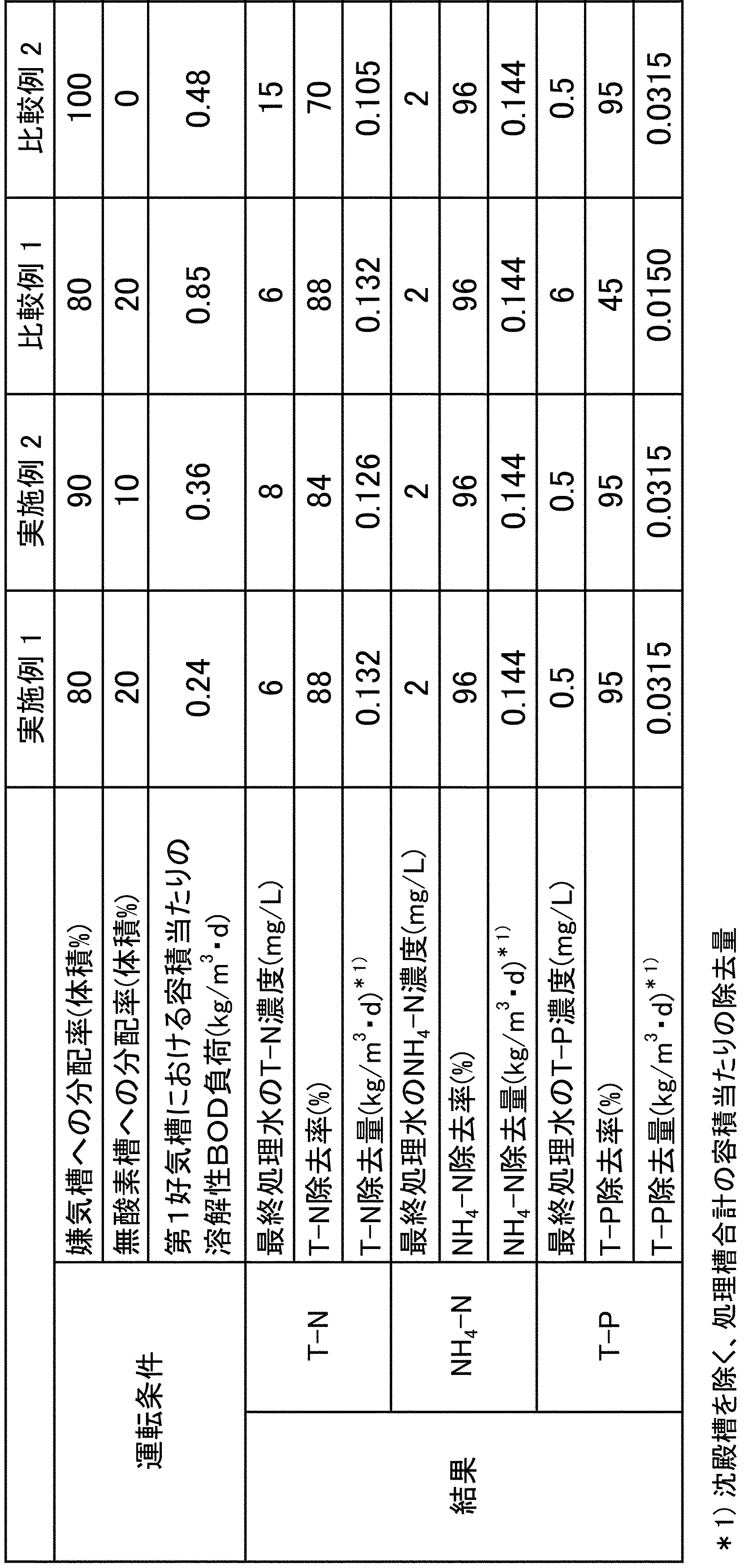
以上の実施例及び比較例の結果から、第1好気槽2の容積当たりの溶解性BOD負荷を所定の範囲に保ち、有機性排水の一部を無酸素槽3に供給することによって、窒素及びリンを効率的に除去することができた。
From the results of the above Examples and Comparative Examples, nitrogen was obtained by keeping the soluble BOD load per volume of the first aerobic tank 2 within a predetermined range and supplying a part of the organic wastewater to the oxygen-free tank 3. And phosphorus could be removed efficiently.
1 嫌気槽
2 第1好気槽
3 無酸素槽
4 第2好気槽
5 固液分離装置
6、7A、7B 排水管
8、9、10、11、12 処理水管
13 汚泥管
14 、15 返送汚泥管
16 汚泥排出管
17、21 撹拌機
18 担体
19 スクリーン
20、22 散気装置
1Anaerobic tank 2 1st aerobic tank 3 Anoxic tank 4 2nd aerobic tank 5 Solid- liquid separator 6, 7A, 7B Drain pipe 8, 9, 10, 11, 12 Treated water pipe 13 Sludge pipe 14, 15 Return sludge Pipe 16 Sludge discharge pipe 17, 21 Stirrer 18 Carrier 19 Screen 20, 22 Air diffuser
2 第1好気槽
3 無酸素槽
4 第2好気槽
5 固液分離装置
6、7A、7B 排水管
8、9、10、11、12 処理水管
13 汚泥管
14 、15 返送汚泥管
16 汚泥排出管
17、21 撹拌機
18 担体
19 スクリーン
20、22 散気装置
1
Claims (6)
- 嫌気槽、第1好気槽、無酸素槽、第2好気槽及び固液分離装置をこの順序で備え、前記第1好気槽に担体が充填された処理装置を用いて、窒素及びリンを含有する有機性排水に対して生物処理を行う排水処理方法であって;
前記有機性排水を前記嫌気槽及び前記無酸素槽に供給する工程1と、
前記嫌気槽内において、活性汚泥中の細菌にリンを放出させて1次処理水を排出する工程2と、
前記第1好気槽内において、前記1次処理水に対して、担体に担持された細菌及び活性汚泥中の細菌により、硝化、脱窒及びリンの吸収を行って2次処理水を排出する工程3と、
前記無酸素槽内において、前記有機性排水及び前記2次処理水の混合水に対して、活性汚泥中の細菌により脱窒を行って3次処理水を排出する工程4と、
前記第2好気槽内において、前記3次処理水に対して、活性汚泥中の細菌により硝化及びリンの吸収を行って4次処理水を排出する工程5と、
前記固液分離装置において、前記4次処理水から汚泥を分離して最終処理水を排出するとともに、分離された前記汚泥の一部を前記嫌気槽に返送する工程6とを有し、
前記第1好気槽における容積当たりの溶解性BOD負荷が0.05~0.60kg/m3・dであることを特徴とする排水処理方法。 Nitrogen and phosphorus are provided in this order with an anaerobic tank, a first aerobic tank, an oxygen-free tank, a second aerobic tank, and a solid-liquid separator, and the first aerobic tank is filled with a carrier. It is a wastewater treatment method that biologically treats organic wastewater containing
Step 1 of supplying the organic wastewater to the anaerobic tank and the oxygen-free tank,
In the anaerobic tank, the step 2 of releasing phosphorus to the bacteria in the activated sludge to discharge the primary treated water,
In the first aerobic tank, the primary treated water is nitrified, denitrified and absorbed by phosphorus by the bacteria carried on the carrier and the bacteria in the activated sludge, and the secondary treated water is discharged. Step 3 and
In the oxygen-free tank, the step 4 of denitrifying the mixed water of the organic wastewater and the secondary treated water with bacteria in the activated sludge to discharge the tertiary treated water.
In the second aerobic tank, the third treated water is nitrified and absorbed by bacteria in the activated sludge to discharge the fourth treated water.
The solid-liquid separation device includes a step 6 of separating sludge from the fourth treated water, discharging the final treated water, and returning a part of the separated sludge to the anaerobic tank.
A wastewater treatment method characterized in that the soluble BOD load per volume in the first aerobic tank is 0.05 to 0.60 kg / m 3 · d. - 工程1において、前記有機性排水の60~95体積%を前記嫌気槽に供給するとともに、前記有機性排水の5~40体積%を前記無酸素槽に供給する請求項1に記載の排水処理方法。 The wastewater treatment method according to claim 1, wherein in step 1, 60 to 95% by volume of the organic wastewater is supplied to the anaerobic tank and 5 to 40% by volume of the organic wastewater is supplied to the oxygen-free tank. ..
- 工程2において、前記嫌気槽の汚泥当たりのBOD負荷が0.20~14.5kg-BOD/kg-MLSS・dである請求項1又は2に記載の排水処理方法。 The wastewater treatment method according to claim 1 or 2, wherein in step 2, the BOD load per sludge in the anaerobic tank is 0.20 to 14.5 kg-BOD / kg-MLSS · d.
- 前記担体が連通孔を有する請求項1~3のいずれかに記載の排水処理方法。 The wastewater treatment method according to any one of claims 1 to 3, wherein the carrier has a communication hole.
- 前記担体がポリビニルアルコールゲル担体である請求項1~4のいずれかに記載の排水処理方法。 The wastewater treatment method according to any one of claims 1 to 4, wherein the carrier is a polyvinyl alcohol gel carrier.
- 工程6において、分離された前記汚泥の一部を前記嫌気槽と前記無酸素槽の両方に返送する請求項1~5のいずれかに記載の排水処理方法。
The wastewater treatment method according to any one of claims 1 to 5, wherein a part of the separated sludge is returned to both the anaerobic tank and the oxygen-free tank in the step 6.
Applications Claiming Priority (2)
| Application Number | Priority Date | Filing Date | Title |
|---|---|---|---|
| JP2020044347A JP2023046420A (en) | 2020-03-13 | 2020-03-13 | Wastewater treatment method |
| JP2020-044347 | 2020-03-13 |
Publications (1)
| Publication Number | Publication Date |
|---|---|
| WO2021182603A1 true WO2021182603A1 (en) | 2021-09-16 |
Family
ID=77671757
Family Applications (1)
| Application Number | Title | Priority Date | Filing Date |
|---|---|---|---|
| PCT/JP2021/010002 WO2021182603A1 (en) | 2020-03-13 | 2021-03-12 | Wastewater treatment method |
Country Status (2)
| Country | Link |
|---|---|
| JP (1) | JP2023046420A (en) |
| WO (1) | WO2021182603A1 (en) |
Citations (7)
| Publication number | Priority date | Publication date | Assignee | Title |
|---|---|---|---|---|
| JPS5573398A (en) * | 1978-11-30 | 1980-06-03 | Ebara Infilco Co Ltd | Biological denitrification and dephosphorization of waste water |
| JPH01242198A (en) * | 1988-03-25 | 1989-09-27 | Toshiba Corp | Controlling device for stepped nitration denitrification process |
| JPH05169087A (en) * | 1991-12-19 | 1993-07-09 | Unitika Ltd | Treatment of nitrogen and phosphorus in sewage |
| JPH08168795A (en) * | 1994-12-19 | 1996-07-02 | Ngk Insulators Ltd | Sewage denitrification and dephosphorization treatment and device used for the same |
| JPH10314782A (en) * | 1997-05-22 | 1998-12-02 | Kuraray Co Ltd | Water treatment carrier, its manufacture and method for nitrification and denitrification using that |
| JP2005246134A (en) * | 2004-03-01 | 2005-09-15 | Mitsubishi Heavy Ind Ltd | Method for treating organic wastewater |
| JP2014184396A (en) * | 2013-03-22 | 2014-10-02 | Hitachi Ltd | Water treatment apparatus and method |
-
2020
- 2020-03-13 JP JP2020044347A patent/JP2023046420A/en active Pending
-
2021
- 2021-03-12 WO PCT/JP2021/010002 patent/WO2021182603A1/en active Application Filing
Patent Citations (7)
| Publication number | Priority date | Publication date | Assignee | Title |
|---|---|---|---|---|
| JPS5573398A (en) * | 1978-11-30 | 1980-06-03 | Ebara Infilco Co Ltd | Biological denitrification and dephosphorization of waste water |
| JPH01242198A (en) * | 1988-03-25 | 1989-09-27 | Toshiba Corp | Controlling device for stepped nitration denitrification process |
| JPH05169087A (en) * | 1991-12-19 | 1993-07-09 | Unitika Ltd | Treatment of nitrogen and phosphorus in sewage |
| JPH08168795A (en) * | 1994-12-19 | 1996-07-02 | Ngk Insulators Ltd | Sewage denitrification and dephosphorization treatment and device used for the same |
| JPH10314782A (en) * | 1997-05-22 | 1998-12-02 | Kuraray Co Ltd | Water treatment carrier, its manufacture and method for nitrification and denitrification using that |
| JP2005246134A (en) * | 2004-03-01 | 2005-09-15 | Mitsubishi Heavy Ind Ltd | Method for treating organic wastewater |
| JP2014184396A (en) * | 2013-03-22 | 2014-10-02 | Hitachi Ltd | Water treatment apparatus and method |
Also Published As
| Publication number | Publication date |
|---|---|
| JP2023046420A (en) | 2023-04-05 |
Similar Documents
| Publication | Publication Date | Title |
|---|---|---|
| JP4508694B2 (en) | Water treatment method and apparatus | |
| CA2748534C (en) | Method and device for removing biological nitrogen and support therefor | |
| KR100767724B1 (en) | A method and an apparatus for waste water treatment through biological system combined with flotation separation of activated sluge | |
| KR100271942B1 (en) | Method for treating high density waste water and apparatus therefore using soil microbe with do controlling aeration tank | |
| KR101603540B1 (en) | Waste water treatment system for high density nitrogen remove and sludge reduction with anaerobic inter-barrier and fluidized media | |
| KR101010053B1 (en) | Apparatus for treating wastewater | |
| JP4915036B2 (en) | Denitrification method and denitrification apparatus | |
| JP4867098B2 (en) | Biological denitrification method and apparatus | |
| JP2001314885A (en) | High load biological treatment method | |
| WO2021182603A1 (en) | Wastewater treatment method | |
| JP3136902B2 (en) | Wastewater treatment method | |
| JP4027217B2 (en) | Livestock wastewater treatment equipment | |
| KR101932611B1 (en) | Advanced water treatment system using Heat-Recovery system for Prevention of Microorganism Activation Reduction by temperature difference of water treatment step | |
| SG186810A1 (en) | Sewage treatment apparatus | |
| JP2004255269A (en) | Denitrification method and denitrification apparatus | |
| Wessman et al. | Increasing the capacity for treatment of chemical plant wastewater by replacing existing suspended carrier media with Kaldnes Moving Bed (TM) media at a plant in Singapore | |
| JP4796852B2 (en) | Wastewater treatment equipment | |
| JPH02237698A (en) | Biological removing method of nitrogen and phosphorus and its apparatus | |
| JPH10296283A (en) | Carrier separating method for biological reaction tank using carrier combinedly | |
| JP2001179280A (en) | Method and apparatus for treating wastewater | |
| JP2002177986A (en) | Biological denitrification equipment | |
| KR20220078024A (en) | Apparatus and Method for Treating Anaerobic Digestive Fluid | |
| WO2019198803A1 (en) | Wastewater treatment method | |
| JP2000107797A (en) | Purification method and apparatus | |
| JP3558204B2 (en) | Wastewater biological treatment equipment |
Legal Events
| Date | Code | Title | Description |
|---|---|---|---|
| 121 | Ep: the epo has been informed by wipo that ep was designated in this application |
Ref document number: 21768427 Country of ref document: EP Kind code of ref document: A1 |
|
| NENP | Non-entry into the national phase |
Ref country code: DE |
|
| 122 | Ep: pct application non-entry in european phase |
Ref document number: 21768427 Country of ref document: EP Kind code of ref document: A1 |
|
| NENP | Non-entry into the national phase |
Ref country code: JP |