WO2021182494A1 - 機器保護部材および機器保護部材の製造方法 - Google Patents
機器保護部材および機器保護部材の製造方法 Download PDFInfo
- Publication number
- WO2021182494A1 WO2021182494A1 PCT/JP2021/009431 JP2021009431W WO2021182494A1 WO 2021182494 A1 WO2021182494 A1 WO 2021182494A1 JP 2021009431 W JP2021009431 W JP 2021009431W WO 2021182494 A1 WO2021182494 A1 WO 2021182494A1
- Authority
- WO
- WIPO (PCT)
- Prior art keywords
- wall portion
- edge
- protection member
- gap
- accommodating
- Prior art date
- Legal status (The legal status is an assumption and is not a legal conclusion. Google has not performed a legal analysis and makes no representation as to the accuracy of the status listed.)
- Ceased
Links
Images




Classifications
-
- B—PERFORMING OPERATIONS; TRANSPORTING
- B60—VEHICLES IN GENERAL
- B60R—VEHICLES, VEHICLE FITTINGS, OR VEHICLE PARTS, NOT OTHERWISE PROVIDED FOR
- B60R16/00—Electric or fluid circuits specially adapted for vehicles and not otherwise provided for; Arrangement of elements of electric or fluid circuits specially adapted for vehicles and not otherwise provided for
- B60R16/02—Electric or fluid circuits specially adapted for vehicles and not otherwise provided for; Arrangement of elements of electric or fluid circuits specially adapted for vehicles and not otherwise provided for electric constitutive elements
-
- F—MECHANICAL ENGINEERING; LIGHTING; HEATING; WEAPONS; BLASTING
- F01—MACHINES OR ENGINES IN GENERAL; ENGINE PLANTS IN GENERAL; STEAM ENGINES
- F01N—GAS-FLOW SILENCERS OR EXHAUST APPARATUS FOR MACHINES OR ENGINES IN GENERAL; GAS-FLOW SILENCERS OR EXHAUST APPARATUS FOR INTERNAL-COMBUSTION ENGINES
- F01N3/00—Exhaust or silencing apparatus having means for purifying, rendering innocuous, or otherwise treating exhaust
- F01N3/08—Exhaust or silencing apparatus having means for purifying, rendering innocuous, or otherwise treating exhaust for rendering innocuous
-
- Y—GENERAL TAGGING OF NEW TECHNOLOGICAL DEVELOPMENTS; GENERAL TAGGING OF CROSS-SECTIONAL TECHNOLOGIES SPANNING OVER SEVERAL SECTIONS OF THE IPC; TECHNICAL SUBJECTS COVERED BY FORMER USPC CROSS-REFERENCE ART COLLECTIONS [XRACs] AND DIGESTS
- Y02—TECHNOLOGIES OR APPLICATIONS FOR MITIGATION OR ADAPTATION AGAINST CLIMATE CHANGE
- Y02A—TECHNOLOGIES FOR ADAPTATION TO CLIMATE CHANGE
- Y02A50/00—TECHNOLOGIES FOR ADAPTATION TO CLIMATE CHANGE in human health protection, e.g. against extreme weather
- Y02A50/20—Air quality improvement or preservation, e.g. vehicle emission control or emission reduction by using catalytic converters
Definitions
- This disclosure relates to a device protection member and a method for manufacturing the device protection member.
- the device protection member has a wall portion formed so as to stand up from a housing portion in which the electronic device is arranged, and can protect the electronic device from a fluid such as water radiated from the surroundings.
- the vehicle is equipped with various devices for arranging electronic devices outside.
- Patent Document 1 discloses an exhaust gas purification device capable of preventing deterioration of purification performance.
- This exhaust gas purification device is for purifying exhaust gas using urea water, and is arranged outside the vehicle.
- the device protection member may have a gap between the wall portion raised from the accommodating portion, and it is difficult to reliably protect the electronic device.
- An object of the present disclosure is to provide a device protection member that reliably protects an electronic device and a method for manufacturing the device protection member.
- the device protection member has a plate shape, is arranged at a housing portion where electronic devices of a vehicle are arranged, and a first wall which is arranged at a first edge portion of the housing portion and is raised from the housing portion.
- the portion is arranged at the second edge portion of the accommodating portion intersecting the first edge portion, and is raised from the accommodating portion so as to face each other with a gap between the side edge portion of the first wall portion.
- the second wall portion is provided with a second wall portion, and the second wall portion has an extension portion formed so that the side edge portion projects to the outside of the first wall portion and hides the gap.
- the method for manufacturing the device protection member according to the present disclosure includes a step of forming a notch in the first edge portion of the plate-shaped member, raising the first edge portion from the notch to form the first wall portion, and forming the first wall portion.
- a first wall portion is formed by raising a second edge portion that intersects the first edge portion and forming a second wall portion that faces the side edge portion of the first wall portion with a gap.
- the step of forming the accommodating portion including the step of forming the accommodating portion for arranging the electronic devices of the vehicle inside the wall portion and the second wall portion, is performed by cutting into the side edge portion of the second wall portion.
- An extension portion is formed that protrudes to the outside of the first wall portion and hides the gap.
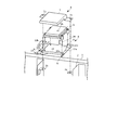
- FIG. 1 is a diagram showing a configuration of a vehicle provided with a device protection member according to the first embodiment of the present disclosure.
- FIG. 2 is a diagram showing a configuration of a device protection member.
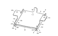
- FIG. 3 is a diagram showing the configuration of the lower cover portion.
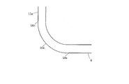
- FIG. 4 is a diagram showing how the corners are curved.
- FIG. 5 is a diagram showing the configuration of the extension portion.
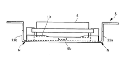
- FIG. 6A is a diagram showing how the side wall portion, the front wall portion, and the rear wall portion hide the communication holes.
- FIG. 6B is a diagram showing how the side wall portion, the front wall portion, and the rear wall portion hide the communication holes.
- FIG. 7 is a diagram showing a state in which a device protection member is manufactured.
- FIG. 8 is a diagram showing the configuration of the lower cover portion of the second embodiment.
- FIG. 1 shows the configuration of a vehicle provided with the device protection member according to the first embodiment of the present disclosure.
- the vehicle has a vehicle frame 1, a support 2, a purification device 3, and a device protection member 4.
- the vehicle frame 1 is a so-called chassis frame that supports each part of the vehicle, and is arranged so as to extend in the front-rear direction of the vehicle.
- the support 2 supports the purification device 3 with respect to the vehicle frame 1 and is fixed to the right side of the vehicle frame 1.
- the purification device 3 has a tank 5 and a control device 6.
- the tank 5 contains a reducing agent supplied into an exhaust pipe (not shown). Examples of the reducing agent include urea water and the like.
- the control device 6 is connected to an injector (not shown) via wiring 6a or the like to control the discharge of urea water from the injector.
- the control device 6 constitutes the electronic device of the present disclosure.
- the injector is arranged in the exhaust pipe and connected to the tank 5, and under the control of the control device 6, the reducing agent contained in the tank 5 is discharged into the exhaust pipe.
- the device protection member 4 is fixed to the support 2 and arranged so as to cover the control device 6.
- the device protection member 4 has an upper cover portion 7 and a lower cover portion 8.
- the upper cover portion 7 protects the control device 6 from a fluid such as water, and is formed so as to cover the upper portion of the control device 6. Further, a pair of fixing portions 7a and 7b projecting from the front of the vehicle and the rear of the vehicle are arranged on the side portion of the upper cover portion 7.
- the lower cover portion 8 protects the control device 6 from a fluid such as water, and is formed so as to cover the lower part of the control device 6. That is, the lower cover portion 8 is arranged so as to sandwich and accommodate the control device 6 with the upper cover portion 7.
- the lower cover portion 8 has an accommodating portion 9, a side wall portion 10, a front wall portion 11a, and a rear wall portion 11b.
- the accommodating portion 9 has a rectangular plate shape, and the control device 6 is arranged on the upper side thereof.
- Four fixing holes for fixing the control device 6 are formed in the accommodating portion 9, and the control device 6 is fixed by a fixing tool such as a bolt (not shown).
- the control device 6 has a communication hole 6b formed on the lower surface facing the accommodating portion 9 to communicate the outside and the inside.
- the communication hole 6b suppresses, for example, the pressure difference between the inside and outside of the control device 6 to prevent the generation of moisture inside the device.
- the side wall portion 10 is integrally connected to the right edge portion of the accommodating portion 9 facing the right side of the vehicle, and is formed so as to stand up from the accommodating portion 9.
- the side wall portion 10 constitutes the first wall portion of the present disclosure.
- the front wall portion 11a is integrally connected to the leading edge portion orthogonal to the right edge portion of the accommodating portion 9, that is, the leading edge portion facing the front of the vehicle, and is formed so as to rise upward from the accommodating portion 9. At this time, the front wall portion 11a is formed so as to face the side edge portion 10a of the side wall portion 10 with a gap N.
- the rear wall portion 11b is integrally connected to the trailing edge portion orthogonal to the right edge portion of the accommodating portion 9, that is, the trailing edge portion facing the rear of the vehicle, and is formed so as to rise upward from the accommodating portion 9. At this time, the rear wall portion 11b is formed so as to face the side edge portion 10b of the side wall portion 10 with a gap N.
- the front wall portion 11a and the rear wall portion 11b form the second wall portion of the present disclosure.
- the lower cover portion 8 is provided with fixing portions 12a and 12b, a wiring mounting portion 13, and a contact portion 14.
- the fixing portions 12a and 12b are arranged corresponding to the front wall portion 11a and the rear wall portion 11b, respectively.
- the fixing portion 12a is arranged so as to project forward from the position corresponding to the fixing portion 7a of the upper cover portion 7 on the front wall portion 11a.
- the fixing portion 12b is arranged so as to project rearward from the position corresponding to the fixing portion 7b of the upper cover portion 7 on the rear wall portion 11b.
- flange portions 2a and 2b are arranged on the support 2.
- the fixing portions 12a and 12b are fixed to the flange portions 2a and 2b of the support 2 together with the fixing portions 7a and 7b of the upper cover portion 7 by fixing tools such as bolts (not shown).
- the wiring attachment portion 13 is arranged so as to project in front of the side wall portion 10, and for example, the wiring 6a of the control device 6 is attached.
- the contact portion 14 is erected upward from the left edge portion of the accommodating portion 9 facing the left side of the vehicle, and is arranged so as to face the left side portion of the control device 6.
- the contact portion 14 is formed so as to come into contact with the control device 6 when the control device 6 is arranged in the accommodating portion 9 in a direction different from the normal direction.
- the front wall portion 11a and the rear wall portion 11b are formed so that the side edge portion on the right side of the vehicle protrudes to the outside of the side wall portion 10, that is, protrudes to the right side of the vehicle to hide the gap N from the outside. It has the extended portions 15a and 15b.
- the extension portions 15a and 15b are arranged so that the lower edge portions 17a and 17b on the corner portions 16a and 16b side of the upper edge portion and the lower edge portion extending in the protruding direction are separated from the accommodating portion 9.
- the corner portions 16a and 16b are connecting portions connecting the front wall portion 11a and the rear wall portion 11b and the accommodating portion 9.
- a notch S is formed at the root portion of the extension portions 15a and 15b protruding outward from the corner portions 16a and 16b side upward.
- the extension portions 15a and 15b are arranged so as to hide all the communication holes 6b of the control device 6 from the gap N. That is, the extension portions 15a and 15b are arranged so that the communication holes 6b cannot be directly seen from the outside through the gap N.
- the front wall portion 11a and the rear wall portion 11b are raised from the accommodating portion 9 so that the corner portions 16a and 16b are curved.
- the front wall portion 11a is raised so that the corner portion 16a is curved from the start end 18a to the end end 18b and has a predetermined bending radius.
- the extension portion 15a is formed so that the lower edge portion 17a extends toward the start end 18a, that is, downward from the curved end 18b of the corner portion 16a.
- the lower edge portion 17a of the extension portion 15a is formed so as to extend downward to a position corresponding to the start end 18a.
- the extension portion 15a is formed so as to hide the gap N to the lower end.
- the extension portion 15a is formed so as to hide the side wall portion 10 from the direction orthogonal to the front wall portion 11a.
- the front wall portion 11a is formed so that the tip portion of the notch S extends upward beyond the curved end 18b of the corner portion 16a.
- the side wall portion 10 has a height equal to or higher than the height position of the communication hole 6b of the control device 6, and hides all of the communication hole 6b from the direction orthogonal to the side wall portion 10. It is formed.
- the front wall portion 11a has a height equal to or higher than the height position of the communication hole 6b of the control device 6, and hides all of the communication holes 6b from the direction orthogonal to the front wall portion 11a. It is formed like this.
- cuts 103a and 103b are formed in the vicinity of both ends of the edge 102 of the rectangular plate-shaped member 101.
- the fixing portions 12a and 12b and the wiring mounting portion 13 are omitted.
- the cuts 103a and 103b are formed at positions corresponding to the side edge portions 10a and 10b of the side wall portion 10. At this time, the cuts 103a and 103b are formed so as to extend in a direction orthogonal to the edge portion 102 by a length corresponding to the height of the side wall portion 10.
- the cuts 105a and 105b extending from the tips of the cuts 103a and 103b toward the edges 104a and 104b orthogonal to the edge 102 are formed, respectively. That is, the cuts 105a and 105b are formed so as to extend in a direction orthogonal to the cuts 103a and 103b. Here, the cuts 105a and 105b are formed so as to extend longer than the end 18b of the corners 16a and 16b from the position corresponding to the start 18a of the corners 16a and 16b.
- the edge portion 102 is bent upward from the vicinity of the tip portions of the cuts 103a and 103b to stand up. Further, the edges 104a and 104b are bent upward from the vicinity of the base ends of the notches 105a and 105b to stand up. As a result, as shown in FIG. 3, the side wall portion 10, the front wall portion 11a, and the rear wall portion 11b that are raised upward from the accommodating portion 9 are formed. Further, the notch S is formed by the notches 105a and 105b.
- the front wall portion 11a and the rear wall portion 11b are raised so as to face each other with a gap N between them and the side wall portion 10.
- the front wall portion 11a and the rear wall portion 11b are raised so that the corner portions 16a and 16b are curved, and the gap N is caused by the curvature of the corner portions 16a and 16b. Will occur.
- a gap N is generated due to the curvature of the corner portions 16a and 16b, and the device protection member.
- a fluid such as water may enter through the gap N.
- extension portions 15a and 15b are formed on the side edges of the front wall portion 11a and the rear wall portion 11b so as to protrude to the outside of the side wall portion 10 and hide the gap N.
- the extension portions 15a and 15b do not need to hide all of the gap N, and may be formed so as to hide a part of the gap N from the outside.
- the cuts 103a and 103b are preferably formed linearly, that is, formed so as to extend in a direction orthogonal to the edge 102 with a small width. As a result, the gaps N can be formed at small intervals.
- the extension portions 15a and 15b can be separated from the curvature of the corner portions 16a and 16b. That is, the lower edge portions 17a and 17b of the extension portions 15a and 15b are formed so as to extend straight downward without being curved together with the corner portions 16a and 16b. As a result, as shown in FIG. 5, the lower edge portions 17a and 17b of the extension portions 15a and 15b can be formed so as to extend to the positions corresponding to the curved start ends 18a of the corner portions 16a and 16b, and the gap N can be formed. You can hide up to the bottom.
- the cuts 105a and 105b are formed linearly, that is, formed so as to extend toward the edges 104a and 104b with a small width. Thereby, the notch S can be formed with a small width.
- the notches 105a and 105b are formed so as to extend beyond the curved end 18b of the corner portions 16a and 16b. As a result, the corner portions 16a and 16b can be easily bent to raise the front wall portion 11a and the rear wall portion 11b.
- the cuts 103a and 103b and the cuts 105a and 105b are formed at a length and position such that the extension portions 15a and 15b hide all the communication holes 6b of the control device 6 from the gap N.
- the extension portions 15a and 15b can be formed so as to hide all of the communication holes 6b from the gap N.
- the lower cover portion 8 in which the accommodating portion 9 is arranged can be formed inside the side wall portion 10, the front wall portion 11a, and the rear wall portion 11b. Since the lower cover portion 8 is formed by bending the plate-shaped member 101, it can be formed by a simple method, and the labor thereof can be suppressed. On the other hand, the upper cover portion 7 is formed so as to cover the upper portion of the control device 6 from the plate-shaped member.
- the device protection member 4 can be manufactured. As shown in FIG. 2, the manufactured device protection member 4 is arranged so as to sandwich the control device 6 in the vertical direction between the upper cover portion 7 and the lower cover portion 8, and is fixed to the right side portion of the vehicle frame 1. It is fixed to the support 2. At this time, since the fixing portions 7a and 7b and the fixing portions 12a and 12b are arranged horizontally, the device protection member 4 is fixed by using a fixture while being placed on the flange portions 2a and 2b of the support 2. can do. Therefore, the device protection member 4 can be easily fixed to the vehicle.
- control device 6 of the purification device 3 since the control device 6 of the purification device 3 is arranged outside the vehicle, there is a risk of being frequently exposed to a fluid such as water.
- a fluid such as water.
- commercial vehicles such as trucks are exposed to a strong force of fluid because they are washed using, for example, a high-pressure washer. Therefore, even if a mechanism such as a valve for preventing the intrusion of the fluid is provided in the communication hole 6b of the control device 6, the fluid may invade the inside through the communication hole 6b.
- the control device 6 can be protected from the fluid.
- the extension portions 15a and 15b are formed so as to protrude to the outside of the side wall portion 10 and hide the gap N. Therefore, it is possible to prevent the fluid from entering through the gap N and reliably protect the control device 6.
- extension portions 15a and 15b are arranged so as to hide all of the communication holes 6b of the control device 6 from the gap N, it is possible to prevent the fluid from directly flying into the communication holes 6b and to prevent the fluid from flying directly into the communication holes 6b. Can be protected more reliably. Therefore, it is preferable that the extension portions 15a and 15b change their positions and sizes with respect to the gap N so as to hide all of the communication holes 6b from the gap N according to the positions of the communication holes 6b.
- the lower edge portions 17a and 17b of the extension portions 15a and 15b are formed so as to extend downward from the curved end 18b of the corner portions 16a and 16b. As a result, it is possible to suppress the intrusion of fluid from the gap N and more reliably protect the control device 6. At this time, it is preferable that the lower edge portions 17a and 17b of the extension portions 15a and 15b are formed so as to extend to a position corresponding to the curved start end 18a of the corner portions 16a and 16b. As a result, the gap N can be hidden to the lower end, and the control device 6 can be protected more reliably.
- the front wall portion 11a and the rear wall portion 11b are formed so that the tip end portion of the notch S extends upward beyond the curved end 18b of the corner portions 16a and 16b.
- the extension portions 15a and 15b can be separated from the curvature of the corner portions 16a and 16b, and the lower edge portions 17a and 17b can be formed so as to extend downward. Therefore, the control device 6 can be protected more reliably.
- the notch S is formed so as to face a direction orthogonal to the front wall portion 11a and the rear wall portion 11b. Therefore, it is possible to prevent the fluid from entering the communication hole 6b and more reliably protect the control device 6.
- the extension portions 15a and 15b are formed so as to project to the outside of the side wall portion 10 and hide the gap N, so that the invasion of fluid from the gap N is suppressed and the control device 6 is operated. It can be reliably protected.
- extension portions 15a and 15b are arranged on the front wall portion 11a and the rear wall portion 11b, but can also be arranged on the side wall portion 10.
- extension portions 21a and 21b can be arranged on both side edges of the side wall portion 10 of the first embodiment.
- the extension portion 21a is arranged so as to project toward the front of the vehicle to the outside of the front wall portion 11a and hide the gap N formed between the side wall portion 10 and the front wall portion 11a.
- the extension portion 21b is arranged so as to project toward the rear of the vehicle to the outside of the rear wall portion 11b and hide the gap N formed between the side wall portion 10 and the rear wall portion 11b.
- the front wall portion 11a and the rear wall portion 11b form the first wall portion of the present disclosure
- the side wall portion 10 constitutes the second wall portion of the present disclosure.
- the extension portion is as in the first embodiment. It is preferable to arrange the 15a and 15b on the front wall portion 11a and the rear wall portion 11b. Thereby, the invasion of the fluid from the gap N can be suppressed more reliably.
- the extension portions 21a and 21b are formed so as to project to the outside of the front wall portion 11a and the rear wall portion 11b to hide the gap N, so that the invasion of fluid from the gap N is suppressed.
- the control device 6 can be reliably protected.
- the extension portion is arranged on the lower cover portion 8, but it is limited to this as long as it is formed so as to project to the outside of the wall portion and hide the gap N. It is not something that can be done.
- the extension portion may be arranged on the front wall portion and the rear wall portion of the upper cover portion 7.
- the front wall portion 11a and the rear wall portion 11b are arranged so as to be orthogonal to the side wall portion 10, but may be arranged so as to intersect the side wall portion 10. , Not limited to this.
- the device protection member according to the present disclosure can be used as a member on which electronic devices of a vehicle are arranged.
Landscapes
- Engineering & Computer Science (AREA)
- Mechanical Engineering (AREA)
- Chemical & Material Sciences (AREA)
- Combustion & Propulsion (AREA)
- General Engineering & Computer Science (AREA)
- Casings For Electric Apparatus (AREA)
- Exhaust Gas After Treatment (AREA)
Abstract
電子機器を確実に保護する機器保護部材および機器保護部材の製造方法を提供する。この機器保護部材は、板形状を有し、車両の電子機器が配置される収容部と、収容部の第1の縁部に配置され、収容部から立ち上げられた第1の壁部と、第1の縁部に交差する収容部の第2の縁部に配置され、第1の壁部の側縁部との間に隙間を空けて対向するように収容部から立ち上げられた第2の壁部とを備え、第2の壁部は、側縁部が第1の壁部の外側まで突出して隙間を隠すように形成された延長部を有する。
Description
本開示は、機器保護部材および機器保護部材の製造方法に関する。
従来から、車両の電子機器を保護する機器保護部材が実用化されている。機器保護部材は、電子機器が配置される収容部から立ち上がるように壁部が形成されており、例えば周囲から放射される水などの流体から電子機器を保護することができる。車両には、外部に電子機器を配置する様々な装置が搭載されている。
例えば、特許文献1には、浄化性能の低下を防止可能な排ガス浄化装置が開示されている。この排ガス浄化装置は、尿素水を用いて排出ガスを浄化するためのもので、車両の外部に配置される。
このように、車両の外部に配置される電子機器は、水などの流体を浴びる可能性が高いため、電子機器を確実に保護することが求められる。しかしながら、機器保護部材は、収容部から立ち上げられた壁部と壁部との間に隙間が生じる場合があり、電子機器を確実に保護することが困難であった。
本開示は、電子機器を確実に保護する機器保護部材および機器保護部材の製造方法を提供することを目的とする。
本開示に係る機器保護部材は、板形状を有し、車両の電子機器が配置される収容部と、収容部の第1の縁部に配置され、収容部から立ち上げられた第1の壁部と、第1の縁部に交差する収容部の第2の縁部に配置され、第1の壁部の側縁部との間に隙間を空けて対向するように収容部から立ち上げられた第2の壁部とを備え、第2の壁部は、側縁部が第1の壁部の外側まで突出して隙間を隠すように形成された延長部を有するものである。
本開示に係る機器保護部材の製造方法は、板状部材の第1の縁部に切り込みを形成するステップと、切り込みから第1の縁部を立ち上げて第1の壁部を形成すると共に、第1の縁部に交差する第2の縁部を立ち上げて第1の壁部の側縁部との間に隙間を空けて対向する第2の壁部を形成することにより、第1の壁部および第2の壁部の内側に車両の電子機器を配置する収容部を形成するステップと、を含み、収容部を形成するステップは、切り込みにより、第2の壁部の側縁部に第1の壁部の外側まで突出して隙間を隠す延長部が形成されるものである。
本開示によれば、電子機器を確実に保護することが可能となる。
以下、本開示に係る実施の形態を添付図面に基づいて説明する。
(実施の形態1)
図1に、本開示の実施の形態1に係る機器保護部材を備えた車両の構成を示す。車両は、車両フレーム1と、支持体2と、浄化装置3と、機器保護部材4とを有する。
図1に、本開示の実施の形態1に係る機器保護部材を備えた車両の構成を示す。車両は、車両フレーム1と、支持体2と、浄化装置3と、機器保護部材4とを有する。
車両フレーム1は、車両の各部を支持する、いわゆるシャシフレームで、車両の前後方向に延びるように配置されている。
支持体2は、車両フレーム1に対して浄化装置3を支持するもので、車両フレーム1の右側部に固定されている。
浄化装置3は、タンク5と、制御機器6とを有する。
タンク5は、図示しない排気管内に供給される還元剤が内部に収容されている。還元剤としては、例えば、尿素水などが挙げられる。
タンク5は、図示しない排気管内に供給される還元剤が内部に収容されている。還元剤としては、例えば、尿素水などが挙げられる。
制御機器6は、配線6aなどを介して、図示しないインジェクターに接続され、インジェクターからの尿素水の放出を制御する。この制御機器6は、本開示の電子機器を構成する。
なお、インジェクターは、排気管に配置されると共にタンク5に接続され、制御機器6の制御の下、タンク5に収容された還元剤を排気管内に放出するものである。
なお、インジェクターは、排気管に配置されると共にタンク5に接続され、制御機器6の制御の下、タンク5に収容された還元剤を排気管内に放出するものである。
機器保護部材4は、支持体2に固定され、制御機器6を覆うように配置されている。
次に、機器保護部材4の構成について詳細に説明する。
図2に示すように、機器保護部材4は、上側カバー部7と、下側カバー部8とを有する。
上側カバー部7は、水などの流体から制御機器6を保護するもので、制御機器6の上部を覆うように形成されている。また、上側カバー部7の側部には、車両前方および車両後方にそれぞれ突出する一対の固定部7aおよび7bが配置されている。
上側カバー部7は、水などの流体から制御機器6を保護するもので、制御機器6の上部を覆うように形成されている。また、上側カバー部7の側部には、車両前方および車両後方にそれぞれ突出する一対の固定部7aおよび7bが配置されている。
下側カバー部8は、水などの流体から制御機器6を保護するもので、制御機器6の下部を覆うように形成されている。すなわち、下側カバー部8は、上側カバー部7との間で制御機器6を挟んで収容するように配置されている。下側カバー部8は、収容部9と、側壁部10と、前壁部11aと、後壁部11bとを有する。
収容部9は、矩形の板形状を有し、その上側に制御機器6が配置される。収容部9には、制御機器6を固定するための4つの固定穴が形成されており、図示しないボルトなどの固定具で制御機器6が固定される。
なお、制御機器6は、収容部9に対向する下面に外部と内部を連通する連通孔6bが形成されている。この連通孔6bは、例えば、制御機器6の内外の圧力差を抑制して、機器内部に水分が発生することを防止する。
なお、制御機器6は、収容部9に対向する下面に外部と内部を連通する連通孔6bが形成されている。この連通孔6bは、例えば、制御機器6の内外の圧力差を抑制して、機器内部に水分が発生することを防止する。
側壁部10は、収容部9において車両の右側方を向いた右側縁部に一体に接続され、収容部9から上方に立ち上がるように形成されている。側壁部10は、本開示の第1の壁部を構成する。
前壁部11aは、収容部9において右側縁部に直交する前縁部、すなわち車両前方を向いた前縁部に一体に接続され、収容部9から上方に立ち上がるように形成されている。このとき、前壁部11aは、側壁部10の側縁部10aとの間に隙間Nを空けて対向するように形成されている。
後壁部11bは、収容部9において右側縁部に直交する後縁部、すなわち車両後方を向いた後縁部に一体に接続され、収容部9から上方に立ち上がるように形成されている。このとき、後壁部11bは、側壁部10の側縁部10bとの間に隙間Nを空けて対向するように形成されている。
なお、前壁部11aおよび後壁部11bは、本開示の第2の壁部を構成する。
なお、前壁部11aおよび後壁部11bは、本開示の第2の壁部を構成する。
また、下側カバー部8には、固定部12aおよび12bと、配線取付部13と、接触部14とが配置されている。
固定部12aおよび12bは、前壁部11aおよび後壁部11bにそれぞれ対応して配置されている。固定部12aは、前壁部11aにおいて上側カバー部7の固定部7aに対応する位置から車両前方に突出するように配置されている。一方、固定部12bは、後壁部11bにおいて上側カバー部7の固定部7bに対応する位置から車両後方に突出するように配置されている。ここで、支持体2には、フランジ部2aおよび2bが配置されている。固定部12aおよび12bは、上側カバー部7の固定部7aおよび7bと共に支持体2のフランジ部2aおよび2bに図示しないボルトなどの固定具で固定される。
配線取付部13は、側壁部10の正面に突出するように配置され、例えば、制御機器6の配線6aなどが取り付けられる。
接触部14は、収容部9において車両の左側方を向いた左側縁部から上方に立設され、制御機器6の左側部に対向して配置されている。接触部14は、制御機器6が正規の向きと異なる向きで収容部9に配置された場合に、制御機器6に接触するように形成されている。
接触部14は、収容部9において車両の左側方を向いた左側縁部から上方に立設され、制御機器6の左側部に対向して配置されている。接触部14は、制御機器6が正規の向きと異なる向きで収容部9に配置された場合に、制御機器6に接触するように形成されている。
次に、下側カバー部8の構成について詳細に説明する。
図3に示すように、前壁部11aおよび後壁部11bは、車両右側の側縁部が側壁部10の外側まで突出、すなわち車両の右側方に突出して隙間Nを外側から隠すように形成された延長部15aおよび15bを有する。
延長部15aおよび15bは、突出方向に延びる上縁部および下縁部のうち、角部16aおよび16b側の下縁部17aおよび17bが収容部9から切り離されて配置されている。ここで、角部16aおよび16bは、前壁部11aおよび後壁部11bと収容部9との間を接続する接続部分である。そして、外側に突出する延長部15aおよび15bの根元部分には、角部16aおよび16b側から上方に向かって切り込みSが形成されている。
このとき、延長部15aおよび15bは、制御機器6の連通孔6bの全てを隙間Nから隠すように配置されている。すなわち、延長部15aおよび15bは、隙間Nを介して連通孔6bが外側から直接的に見えないように配置されている。
このとき、延長部15aおよび15bは、制御機器6の連通孔6bの全てを隙間Nから隠すように配置されている。すなわち、延長部15aおよび15bは、隙間Nを介して連通孔6bが外側から直接的に見えないように配置されている。
ここで、前壁部11aおよび後壁部11bは、角部16aおよび16bが湾曲するように収容部9から立ち上げられている。例えば、前壁部11aは、図4に示すように、始端18aから終端18bまで角部16aが湾曲して所定の曲げ半径を有するように立ち上げられている。
そして、延長部15aは、図5に示すように、下縁部17aが角部16aの湾曲の終端18bより始端18a側、すなわち下方に延びるように形成されている。具体的には、延長部15aの下縁部17aは、下方に向かって始端18aに対応する位置まで延びるように形成されている。これにより、延長部15aは、隙間Nを下端まで隠すように形成される。また、延長部15aは、前壁部11aに直交する方向から側壁部10を隠すように形成されている。
また、前壁部11aは、切り込みSの先端部が角部16aの湾曲の終端18bを超えて上方に延びるように形成される。
また、前壁部11aは、切り込みSの先端部が角部16aの湾曲の終端18bを超えて上方に延びるように形成される。
また、図6Aに示すように、側壁部10は、制御機器6の連通孔6bの高さ位置以上の高さを有し、側壁部10に直交する方向から連通孔6bの全てを隠すように形成されている。
また、図6Bに示すように、前壁部11aは、制御機器6の連通孔6bの高さ位置以上の高さを有し、前壁部11aに直交する方向から連通孔6bの全てを隠すように形成されている。
また、図6Bに示すように、前壁部11aは、制御機器6の連通孔6bの高さ位置以上の高さを有し、前壁部11aに直交する方向から連通孔6bの全てを隠すように形成されている。
なお、後壁部11bは、前壁部11aと同様の構成を有するため、説明を省略する。
次に、機器保護部材4の製造方法について説明する。
まず、図7に示すように、矩形状の板状部材101の縁部102の両端部近傍に切り込み103aおよび103bを形成する。なお、図7では、固定部12aおよび12b、配線取付部13は省略して示している。
切り込み103aおよび103bは、側壁部10の側縁部10aおよび10bに対応する位置に形成される。このとき、切り込み103aおよび103bは、縁部102に直交する方向に、側壁部10の高さに応じた長さだけ延びるように形成される。
また、切り込み103aおよび103bの先端部から、縁部102に直交する縁部104aおよび104bに向かって延びる切り込み105aおよび105bをそれぞれ形成する。すなわち、切り込み105aおよび105bは、切り込み103aおよび103bに直交する方向に延びるように形成される。ここで、切り込み105aおよび105bは、角部16aおよび16bの始端18aに対応する位置から、角部16aおよび16bの終端18bより長く延びるように形成される。
続いて、切り込み103aおよび103bの先端部近傍から縁部102を上方に屈曲させて立ち上げる。また、切り込み105aおよび105bの基端部近傍から縁部104aおよび104bを上方に屈曲させて立ち上げる。
これにより、図3に示すように、収容部9から上方に立ち上げられた側壁部10、前壁部11aおよび後壁部11bが形成されることになる。また、切り込み105aおよび105bにより切り込みSが形成される。
これにより、図3に示すように、収容部9から上方に立ち上げられた側壁部10、前壁部11aおよび後壁部11bが形成されることになる。また、切り込み105aおよび105bにより切り込みSが形成される。
このとき、前壁部11aおよび後壁部11bは、側壁部10との間に隙間Nを空けて対向するように立ち上げられる。ここで、前壁部11aおよび後壁部11bは、図4に示すように、角部16aおよび16bが湾曲するように立ち上げられており、隙間Nは角部16aおよび16bの湾曲に起因して生じることになる。
一般的に、板状部材101を屈曲させて側壁部10、前壁部11aおよび後壁部11bを形成すると、角部16aおよび16bの湾曲に起因して隙間Nが生じてしまい、機器保護部材4を車両の外部に配置した場合に、隙間Nから水などの流体が侵入するおそれがあった。
そこで、切り込み103aおよび103bを形成することにより、前壁部11aおよび後壁部11bの側縁部に、側壁部10の外側まで突出して隙間Nを隠す延長部15aおよび15bを形成する。このとき、延長部15aおよび15bは、隙間Nの全てを隠す必要は無く、隙間Nの一部を外側から隠すように形成されていればよい。
なお、切り込み103aおよび103bは、線状に形成、すなわち小さな幅で縁部102に直交する方向に延びるように形成することが好ましい。これにより、隙間Nを小さな間隔で形成することができる。
なお、切り込み103aおよび103bは、線状に形成、すなわち小さな幅で縁部102に直交する方向に延びるように形成することが好ましい。これにより、隙間Nを小さな間隔で形成することができる。
また、切り込み105aおよび105bを形成することにより、延長部15aおよび15bを角部16aおよび16bの湾曲から切り離すことができる。すなわち、延長部15aおよび15bの下縁部17aおよび17bが、角部16aおよび16bと共に湾曲されずに、下方に向かって真っ直ぐに延びるように形成される。これにより、図5に示すように、延長部15aおよび15bの下縁部17aおよび17bを角部16aおよび16bの湾曲の始端18aに対応する位置まで延びるように形成することができ、隙間Nを下端まで隠すことができる。
なお、切り込み105aおよび105bは、線状に形成、すなわち小さな幅で縁部104aおよび104bに向かって延びるように形成することが好ましい。これにより、切り込みSを小さな幅で形成することができる。
また、切り込み105aおよび105bは、角部16aおよび16bの湾曲の終端18bを超えて延びるように形成されている。これにより、角部16aおよび16bを容易に屈曲させて前壁部11aおよび後壁部11bを立ち上げることができる。
また、切り込み103aおよび103b、切り込み105aおよび105bは、延長部15aおよび15bが制御機器6の連通孔6bの全てを隙間Nから隠すような長さおよび位置に形成される。これにより、連通孔6bの全てを隙間Nから隠すように延長部15aおよび15bを形成することができる。
このようにして、側壁部10、前壁部11aおよび後壁部11bの内側に収容部9が配置された下側カバー部8を形成することができる。下側カバー部8は、板状部材101を屈曲させて形成されるため、簡便な方法で形成することができ、その労力を抑制することができる。
一方、上側カバー部7が、板状部材から制御機器6の上部を覆うように形成される。
一方、上側カバー部7が、板状部材から制御機器6の上部を覆うように形成される。
このようにして、機器保護部材4を製造することができる。
製造された機器保護部材4は、図2に示すように、上側カバー部7と下側カバー部8で制御機器6を上下方向に挟むように配置され、車両フレーム1の右側部に固定された支持体2に固定される。このとき、固定部7aおよび7b、固定部12aおよび12bが、水平に配置されているため、機器保護部材4を支持体2のフランジ部2aおよび2bに載置した状態で固定具を用いて固定することができる。このため、機器保護部材4を車両に容易に固定することができる。
製造された機器保護部材4は、図2に示すように、上側カバー部7と下側カバー部8で制御機器6を上下方向に挟むように配置され、車両フレーム1の右側部に固定された支持体2に固定される。このとき、固定部7aおよび7b、固定部12aおよび12bが、水平に配置されているため、機器保護部材4を支持体2のフランジ部2aおよび2bに載置した状態で固定具を用いて固定することができる。このため、機器保護部材4を車両に容易に固定することができる。
一般的に、浄化装置3の制御機器6は、車両の外部に配置されるため、水などの流体を頻繁に浴びるおそれがある。特に、トラックなどの商用車は、例えば、高圧洗浄機などを用いて車両を洗浄するため、強い勢いの流体を浴びることになる。このため、制御機器6の連通孔6bに流体の侵入を防ぐ弁などの機構を設けた場合でも、流体が連通孔6bを介して内部に侵入するおそれがある。
そこで、制御機器6を覆うように上側カバー部7と下側カバー部8を配置することにより、制御機器6を流体から保護することができる。
このとき、延長部15aおよび15bが、側壁部10の外側まで突出して隙間Nを隠すように形成されている。このため、隙間Nから流体が侵入することを抑制し、制御機器6を確実に保護することができる。
また、延長部15aおよび15bは、制御機器6の連通孔6bの全てを隙間Nから隠すように配置されるため、流体が連通孔6bに直接的に飛んでくることを抑制し、制御機器6をより確実に保護することができる。
このため、延長部15aおよび15bは、連通孔6bの位置に応じて、連通孔6bの全てを隙間Nから隠すように隙間Nに対する位置および大きさなどを変えることが好ましい。
このため、延長部15aおよび15bは、連通孔6bの位置に応じて、連通孔6bの全てを隙間Nから隠すように隙間Nに対する位置および大きさなどを変えることが好ましい。
また、延長部15aおよび15bの下縁部17aおよび17bが、角部16aおよび16bの湾曲の終端18bより下方に延びるように形成されている。これにより、隙間Nからの流体の侵入を抑制し、制御機器6をより確実に保護することができる。
このとき、延長部15aおよび15bの下縁部17aおよび17bは、角部16aおよび16bの湾曲の始端18aに対応する位置まで延びるように形成することが好ましい。これにより、隙間Nを下端まで隠すことができ、制御機器6をより確実に保護することができる。
このとき、延長部15aおよび15bの下縁部17aおよび17bは、角部16aおよび16bの湾曲の始端18aに対応する位置まで延びるように形成することが好ましい。これにより、隙間Nを下端まで隠すことができ、制御機器6をより確実に保護することができる。
また、前壁部11aおよび後壁部11bは、切り込みSの先端部が角部16aおよび16bの湾曲の終端18bを超えて上方に延びるように形成されている。これにより、延長部15aおよび15bを角部16aおよび16bの湾曲から切り離すことができ、下縁部17aおよび17bを下方に延びるように形成することができる。このため、制御機器6をより確実に保護することができる。
また、切り込みSは、前壁部11aおよび後壁部11bに直交する方向を向くように形成されている。このため、流体が連通孔6bに向かって侵入することを抑制し、制御機器6をより確実に保護することができる。
また、切り込みSは、前壁部11aおよび後壁部11bに直交する方向を向くように形成されている。このため、流体が連通孔6bに向かって侵入することを抑制し、制御機器6をより確実に保護することができる。
本実施の形態によれば、延長部15aおよび15bが、側壁部10の外側まで突出して隙間Nを隠すように形成されるため、隙間Nから流体が侵入することを抑制し、制御機器6を確実に保護することができる。
(実施の形態2)
以下、本開示の実施の形態2について説明する。ここでは、上記の実施の形態1との相違点を中心に説明し、上記の実施の形態1との共通点については、共通の参照符号を使用して、その詳細な説明を省略する。
以下、本開示の実施の形態2について説明する。ここでは、上記の実施の形態1との相違点を中心に説明し、上記の実施の形態1との共通点については、共通の参照符号を使用して、その詳細な説明を省略する。
上記の実施の形態1では、延長部15aおよび15bは、前壁部11aおよび後壁部11bに配置されたが、側壁部10に配置することもできる。
例えば、図8に示すように、実施の形態1の側壁部10の両側縁部に延長部21aおよび21bを配置することができる。
例えば、図8に示すように、実施の形態1の側壁部10の両側縁部に延長部21aおよび21bを配置することができる。
延長部21aは、車両前方に向かって前壁部11aの外側まで突出して、側壁部10と前壁部11aとの間に形成される隙間Nを隠すように配置される。
延長部21bは、車両後方に向かって後壁部11bの外側まで突出して、側壁部10と後壁部11bとの間に形成される隙間Nを隠すように配置される。
延長部21bは、車両後方に向かって後壁部11bの外側まで突出して、側壁部10と後壁部11bとの間に形成される隙間Nを隠すように配置される。
すなわち、前壁部11aおよび後壁部11bが本開示の第1の壁部を構成し、側壁部10が本開示の第2の壁部を構成することになる。
これにより、隙間Nから流体が侵入することを抑制し、制御機器6を確実に保護することができる。
なお、図3に示すように、制御機器6の連通孔6bが、収容部9の中央部近傍で且つ左側縁部近傍に配置されている場合には、実施の形態1のように、延長部15aおよび15bを前壁部11aおよび後壁部11bに配置することが好ましい。これにより、隙間Nからの流体の侵入をより確実に抑制することができる。
なお、図3に示すように、制御機器6の連通孔6bが、収容部9の中央部近傍で且つ左側縁部近傍に配置されている場合には、実施の形態1のように、延長部15aおよび15bを前壁部11aおよび後壁部11bに配置することが好ましい。これにより、隙間Nからの流体の侵入をより確実に抑制することができる。
本実施の形態によれば、延長部21aおよび21bが、前壁部11aおよび後壁部11bの外側まで突出して隙間Nを隠すように形成されるため、隙間Nから流体が侵入することを抑制し、制御機器6を確実に保護することができる。
なお、上記の実施の形態1および2では、延長部は、下側カバー部8に配置されたが、壁部の外側まで突出して隙間Nを隠すように形成されていればよく、これに限られるものではない。例えば、延長部は、上側カバー部7の前壁部および後壁部に配置することもできる。
また、上記の実施の形態1および2では、前壁部11aおよび後壁部11bは、側壁部10に直交するように配置されたが、側壁部10に交差するように配置されていればよく、これに限られるものではない。
その他、上記の実施の形態は、何れも本発明の実施をするにあたっての具体化の一例を示したものに過ぎず、これらによって本発明の技術的範囲が限定的に解釈されてはならないものである。すなわち、本発明はその要旨、またはその主要な特徴から逸脱することなく、様々な形で実施することができる。例えば、上記の実施の形態で説明した各部の形状や個数などについての開示はあくまで例示であり、適宜変更して実施することができる。
本出願は、2020年3月11日付で出願された日本国特許出願(特願2020-042032)に基づくものであり、その内容はここに参照として取り込まれる。
本開示に係る機器保護部材は、車両の電子機器が配置される部材に利用できる。
1 車両フレーム
2 支持体
2a,2b フランジ部
3 浄化装置
4 機器保護部材
5 タンク
6 制御機器
6a 配線
6b 連通孔
7 上側カバー部
7a,7b,12a,12b 固定部
8 下側カバー部
9 収容部
10 側壁部
10a,10b 側縁部
11a 前壁部
11b 後壁部
13 配線取付部
14 接触部
15a,15b,21a,21b 延長部
16a,16b 角部
17a,17b 下縁部
18a 始端
18b 終端
101 板状部材
102,104a,104b 縁部
103a,103b,105a,105b 切り込み
N 隙間
S 切り込み
2 支持体
2a,2b フランジ部
3 浄化装置
4 機器保護部材
5 タンク
6 制御機器
6a 配線
6b 連通孔
7 上側カバー部
7a,7b,12a,12b 固定部
8 下側カバー部
9 収容部
10 側壁部
10a,10b 側縁部
11a 前壁部
11b 後壁部
13 配線取付部
14 接触部
15a,15b,21a,21b 延長部
16a,16b 角部
17a,17b 下縁部
18a 始端
18b 終端
101 板状部材
102,104a,104b 縁部
103a,103b,105a,105b 切り込み
N 隙間
S 切り込み
Claims (6)
- 板形状を有し、車両の電子機器が配置される収容部と、
前記収容部の第1の縁部に配置され、前記収容部から立ち上げられた第1の壁部と、
前記第1の縁部に交差する前記収容部の第2の縁部に配置され、前記第1の壁部の側縁部との間に隙間を空けて対向するように前記収容部から立ち上げられた第2の壁部と
を備え、
前記第2の壁部は、側縁部が前記第1の壁部の外側まで突出して前記隙間を隠すように形成された延長部を有する機器保護部材。 - 前記第2の壁部は、前記収容部との間の角部が湾曲するように立ち上げられると共に、外側に突出する前記延長部の根元部分に前記角部側から切り込みが形成され、
前記延長部は、突出方向に延びる一対の縁部のうち前記角部側の縁部が前記角部の湾曲の終端より始端側に延びるように形成される請求項1に記載の機器保護部材。 - 前記第2の壁部は、前記切り込みの先端部が前記角部の湾曲の終端を超えて延びるように形成される請求項2に記載の機器保護部材。
- 前記電子機器は、外部と内部を連通する連通孔を有し、
前記延長部は、前記連通孔の全てを前記隙間から隠すように配置される請求項1に記載の機器保護部材。 - 前記収容部は、前記車両の側部において前記電子機器の下側に配置され、
前記第1の壁部は、車両側方を向くように前記収容部から上方に立ち上げられた側壁部からなり、
前記第2の壁部は、車両前方を向くように前記収容部から上方に立ち上げられた前壁部と、車両後方を向くように前記収容部から上方に立ち上げられた後壁部とからなる請求項1に記載の機器保護部材。 - 板状部材の第1の縁部に切り込みを形成するステップと、
前記切り込みから前記第1の縁部を立ち上げて第1の壁部を形成すると共に、前記第1の縁部に交差する第2の縁部を立ち上げて前記第1の壁部の側縁部との間に隙間を空けて対向する第2の壁部を形成することにより、前記第1の壁部および前記第2の壁部の内側に車両の電子機器を配置する収容部を形成するステップと、
を含み、
前記収容部を形成するステップは、前記切り込みにより、前記第2の壁部の側縁部に前記第1の壁部の外側まで突出して前記隙間を隠す延長部が形成される機器保護部材の製造方法。
Priority Applications (1)
| Application Number | Priority Date | Filing Date | Title |
|---|---|---|---|
| CN202180017602.6A CN115190851B (zh) | 2020-03-11 | 2021-03-10 | 设备保护部件及设备保护部件的制造方法 |
Applications Claiming Priority (2)
| Application Number | Priority Date | Filing Date | Title |
|---|---|---|---|
| JP2020042032A JP7347274B2 (ja) | 2020-03-11 | 2020-03-11 | 機器保護部材および機器保護部材の製造方法 |
| JP2020-042032 | 2020-03-11 |
Publications (1)
| Publication Number | Publication Date |
|---|---|
| WO2021182494A1 true WO2021182494A1 (ja) | 2021-09-16 |
Family
ID=77672394
Family Applications (1)
| Application Number | Title | Priority Date | Filing Date |
|---|---|---|---|
| PCT/JP2021/009431 Ceased WO2021182494A1 (ja) | 2020-03-11 | 2021-03-10 | 機器保護部材および機器保護部材の製造方法 |
Country Status (3)
| Country | Link |
|---|---|
| JP (1) | JP7347274B2 (ja) |
| CN (1) | CN115190851B (ja) |
| WO (1) | WO2021182494A1 (ja) |
Citations (4)
| Publication number | Priority date | Publication date | Assignee | Title |
|---|---|---|---|---|
| JPS60111073U (ja) * | 1983-12-29 | 1985-07-27 | パイオニア株式会社 | 電気機器のシヤ−シ構造 |
| JPS63200396U (ja) * | 1987-06-12 | 1988-12-23 | ||
| JPH11346065A (ja) * | 1998-06-01 | 1999-12-14 | Canon Inc | 筐体製造方法およびその製造方法により製造された筐体を備えた画像読取装置および画像形成装置 |
| JP2003318567A (ja) * | 2002-04-24 | 2003-11-07 | Shin Kobe Electric Mach Co Ltd | 天板又は底板及びそれらを用いた箱体 |
Family Cites Families (7)
| Publication number | Priority date | Publication date | Assignee | Title |
|---|---|---|---|---|
| JPH06336796A (ja) * | 1993-05-28 | 1994-12-06 | Toho Sheet & Frame Co Ltd | 金属板横葺屋根用ワンピースジョイント金具の製造法 |
| JP3962976B2 (ja) * | 2001-05-09 | 2007-08-22 | オムロン株式会社 | ユニットケース及び回路ユニット |
| JP3105265U (ja) * | 2004-05-17 | 2004-10-21 | 宣得股▲ふん▼有限公司 | 電磁波シールドケース |
| CN201115284Y (zh) * | 2007-09-21 | 2008-09-10 | 光红建圣股份有限公司 | 隔离器 |
| CN206181710U (zh) * | 2016-11-09 | 2017-05-17 | 广东欧珀移动通信有限公司 | 屏蔽罩 |
| JP6457608B1 (ja) * | 2017-10-03 | 2019-01-23 | 日新製鋼株式会社 | 屋根の谷部の構造 |
| CN209101571U (zh) * | 2018-11-02 | 2019-07-12 | Tcl家用电器(中山)有限公司 | 热水器防水结构及热水器 |
-
2020
- 2020-03-11 JP JP2020042032A patent/JP7347274B2/ja active Active
-
2021
- 2021-03-10 CN CN202180017602.6A patent/CN115190851B/zh active Active
- 2021-03-10 WO PCT/JP2021/009431 patent/WO2021182494A1/ja not_active Ceased
Patent Citations (4)
| Publication number | Priority date | Publication date | Assignee | Title |
|---|---|---|---|---|
| JPS60111073U (ja) * | 1983-12-29 | 1985-07-27 | パイオニア株式会社 | 電気機器のシヤ−シ構造 |
| JPS63200396U (ja) * | 1987-06-12 | 1988-12-23 | ||
| JPH11346065A (ja) * | 1998-06-01 | 1999-12-14 | Canon Inc | 筐体製造方法およびその製造方法により製造された筐体を備えた画像読取装置および画像形成装置 |
| JP2003318567A (ja) * | 2002-04-24 | 2003-11-07 | Shin Kobe Electric Mach Co Ltd | 天板又は底板及びそれらを用いた箱体 |
Also Published As
| Publication number | Publication date |
|---|---|
| CN115190851B (zh) | 2026-05-01 |
| JP7347274B2 (ja) | 2023-09-20 |
| JP2021142837A (ja) | 2021-09-24 |
| CN115190851A (zh) | 2022-10-14 |
Similar Documents
| Publication | Publication Date | Title |
|---|---|---|
| US6772982B2 (en) | Mounting structure | |
| KR100985030B1 (ko) | 보호장치가 장착되는 건설기계용 운전실캡 | |
| US20190100162A1 (en) | Sensor protector and vehicle equipped therewith | |
| CN106356483A (zh) | 车辆用电池单元 | |
| JP7347274B2 (ja) | 機器保護部材および機器保護部材の製造方法 | |
| JP7141998B2 (ja) | 保護部材及び保護構造 | |
| JP7195065B2 (ja) | 車載機器の取付構造 | |
| EP3798369B1 (en) | Construction machine | |
| EP1733954A2 (en) | Under-cover mounting structure for an industrial vehicle | |
| JP6067314B2 (ja) | 建設機械 | |
| CN211844082U (zh) | 一种可替换的主动进气格栅的安装支架 | |
| JP2015140049A (ja) | 車両用補機の取付構造 | |
| KR20150057446A (ko) | 가상 엔진음 시스템의 스피커 장착용 브라켓 | |
| JP6935723B2 (ja) | 燃料系部品の保護構造 | |
| JP5604005B2 (ja) | ステアリングホイールユニット | |
| JP2015121162A (ja) | 車両部品用保護板 | |
| KR20060090435A (ko) | 배기관 보호 팁 구조 및 이를 구비한 플라즈마 디스플레이모듈 | |
| CN203876686U (zh) | 一种电热水器的保护结构 | |
| JP2002061227A (ja) | ブルドーザのフロアフレーム及びそのフロアフレームを備えたブルドーザ用rops運転室 | |
| JP5935647B2 (ja) | 取付構造を備える車載機器 | |
| JP2007069724A (ja) | キャブ用保護部材、キャブおよび作業機械 | |
| KR100783896B1 (ko) | 리어범퍼의 테일트림 구조 | |
| CN213743642U (zh) | 一种工程卡车用防扬尘装置 | |
| JP5073045B2 (ja) | 建設機械 | |
| JP7141999B2 (ja) | 保護部材及び保護構造 |
Legal Events
| Date | Code | Title | Description |
|---|---|---|---|
| 121 | Ep: the epo has been informed by wipo that ep was designated in this application |
Ref document number: 21767630 Country of ref document: EP Kind code of ref document: A1 |
|
| NENP | Non-entry into the national phase |
Ref country code: DE |
|
| 122 | Ep: pct application non-entry in european phase |
Ref document number: 21767630 Country of ref document: EP Kind code of ref document: A1 |