WO2021182344A1 - カメラ、カメラボディ及び放熱器 - Google Patents
カメラ、カメラボディ及び放熱器 Download PDFInfo
- Publication number
- WO2021182344A1 WO2021182344A1 PCT/JP2021/008790 JP2021008790W WO2021182344A1 WO 2021182344 A1 WO2021182344 A1 WO 2021182344A1 JP 2021008790 W JP2021008790 W JP 2021008790W WO 2021182344 A1 WO2021182344 A1 WO 2021182344A1
- Authority
- WO
- WIPO (PCT)
- Prior art keywords
- transfer member
- heat transfer
- heat
- battery
- sheet metal
- Prior art date
- Legal status (The legal status is an assumption and is not a legal conclusion. Google has not performed a legal analysis and makes no representation as to the accuracy of the status listed.)
- Ceased
Links
Images













Classifications
-
- H—ELECTRICITY
- H04—ELECTRIC COMMUNICATION TECHNIQUE
- H04N—PICTORIAL COMMUNICATION, e.g. TELEVISION
- H04N23/00—Cameras or camera modules comprising electronic image sensors; Control thereof
- H04N23/50—Constructional details
-
- G—PHYSICS
- G03—PHOTOGRAPHY; CINEMATOGRAPHY; ANALOGOUS TECHNIQUES USING WAVES OTHER THAN OPTICAL WAVES; ELECTROGRAPHY; HOLOGRAPHY
- G03B—APPARATUS OR ARRANGEMENTS FOR TAKING PHOTOGRAPHS OR FOR PROJECTING OR VIEWING THEM; APPARATUS OR ARRANGEMENTS EMPLOYING ANALOGOUS TECHNIQUES USING WAVES OTHER THAN OPTICAL WAVES; ACCESSORIES THEREFOR
- G03B17/00—Details of cameras or camera bodies; Accessories therefor
- G03B17/55—Details of cameras or camera bodies; Accessories therefor with provision for heating or cooling, e.g. in aircraft
Definitions
- the present invention relates to a camera, a camera body and a radiator.
- Patent Documents 1 to 3 A technique is known in which a unit for heat dissipation is attached to a camera body to dissipate heat inside (for example, Patent Documents 1 to 3).
- JP-A-2017-34314 Japanese Unexamined Patent Publication No. 2010-213000 Japanese Unexamined Patent Publication No. 2003-46828
- One embodiment according to the technique of the present disclosure provides a camera, a camera body and a radiator capable of dissipating internal heat to the outside as needed.
- a first battery chamber having a battery insertion port that is opened and closed by a lid and having an opening at an end in the insertion direction of the battery inserted from the battery insertion port, and a first that is arranged in contact with a heat source.
- a second heat transfer member that moves between the heat transfer member, a first position that abuts on the first heat transfer member, and a second position that is separated from the first heat transfer member, and closes the opening at the second position.
- a camera body including a member and a drive mechanism for moving a second heat transfer member between the first position and the second position, and a lid that can be closed and loaded into the battery chamber, and inserted into the battery chamber.
- a radiator having a protrusion at the end in the direction is provided, and when the radiator is loaded into the battery chamber, the protrusion passes through the opening and comes into contact with the second heat transfer member located at the first position, and the first A camera in which a heat transfer member and a radiator are thermally connected via a second heat transfer member.
- the radiator is a housing, a heat radiating member built in the housing, and a part of which protrudes from the housing to form a protruding portion, and a heat radiating member built in the housing and accumulated in the heat radiating member.
- the camera of (1) which is provided with a heat exhaust mechanism for discharging heat to the outside of the camera.
- the heat exhaust mechanism is a fan, the camera of (2).
- the second heat transfer member is a camera according to any one of (2) to (4), which has a higher thermal conductivity than the first heat transfer member.
- At least one abutting portion of the heat radiating member, the first heat transfer member, and the second heat transfer member is provided with a third heat transfer member different from the first heat transfer member and the second heat transfer member.
- One of the cameras from 2) to (5).
- the drive mechanism has an urging member that urges the second heat transfer member toward the second position, and when the radiator is loaded into the battery chamber, the protruding portion resists the urging force of the urging member.
- the camera according to any one of (1) to (6), which presses the second heat transfer member and moves the second heat transfer member to the first position.
- the drive mechanism has a guide rail for guiding the movement of the second heat transfer member and an actuator for moving the second heat transfer member along the guide rail.
- the actuator is the camera of (8) that moves the second heat transfer member to the first position and the second position by electromagnetic force.
- the camera body further includes a heat radiating hole for discharging heat
- the second heat transfer member further has a heat radiating hole opening / closing portion for opening the heat radiating hole at the first position and closing the heat radiating hole at the second position.
- the camera of (10) is provided in the vacant area when the heat dissipation hole is fixed with a tripod or gripped by hand.
- a first battery chamber having a battery insertion port opened and closed by a lid and having an opening at an end in the insertion direction of the battery inserted from the battery insertion port, and a first arranged in contact with a heat source.
- a second heat transfer member that moves between the heat transfer member, a first position that abuts on the first heat transfer member, and a second position that is separated from the first heat transfer member, and closes the opening at the second position.
- a member and a drive mechanism for moving the second heat transfer member between the first position and the second position, the lid can be closed and the heat transfer member can be loaded into the battery chamber, and the end portion in the insertion direction into the battery chamber.
- the protruding portion When a radiator having a protruding portion is loaded into the battery chamber, the protruding portion passes through the opening and comes into contact with the second heat transfer member located at the first position, and the first heat transfer member and the radiator are second-conducted.
- a camera body that is thermally connected via a thermal member.
- a first battery chamber having a battery insertion port opened and closed by a lid and having an opening at an end in the insertion direction of the battery inserted from the battery insertion port, and a first arranged in contact with a heat source.
- a second heat transfer member that moves between the heat transfer member, a first position that abuts on the first heat transfer member, and a second position that is separated from the first heat transfer member, and closes the opening at the second position.
- a radiator that is loaded into the battery compartment of a camera body provided with a member and a drive mechanism for moving a second heat transfer member between the first position and the second position to dissipate heat from a heat source, and is a lid.
- Can be closed and loaded into the battery chamber has a protrusion at the end in the direction of insertion into the battery compartment, and when loaded into the battery chamber, the protrusion is located in the first position through the opening.
- a radiator that comes into contact with a heat transfer member and is thermally connected to the first heat transfer member via the second heat transfer member.
- the figure which shows another example of the holding mechanism of a battery and a radiator The figure which shows another example of the 1st contact and the 2nd contact
- the figure which shows another example of a drive mechanism The figure which shows the operating state of an electromagnet when a battery is loaded.
- the figure which shows the operating state of the electromagnet when a radiator is loaded The figure which shows the schematic structure of the inside of a camera body Bottom view of the camera body
- the figure which shows the relationship between the movement of a slit plate and the opening and closing of a heat dissipation slit The figure which shows the relationship between the movement of a slit plate and the opening and closing of a heat dissipation slit
- the figure which shows the operation state of a slit plate The figure which shows the operation state of a slit plate
- the figure which shows another example of a heat radiating part The figure which shows the operation state of the lower slit plate and the upper slit plate
- the digital camera having the function of shooting a moving image is provided with a heat dissipation mechanism.
- the digital camera is equipped with a heat dissipation mechanism, there is a drawback that the size and weight of the device are increased.
- the digital camera of the present embodiment provides a digital camera capable of dissipating internal heat to the outside as needed.
- FIG. 1 is a diagram showing a system configuration of a digital camera.
- the digital camera 1 of the present embodiment is an interchangeable lens type digital camera, and includes an interchangeable lens 2 and a camera body 10. Further, the digital camera 1 of the present embodiment includes a mountable radiator 100 on the camera body 10. The radiator 100 is a unit that releases heat generated inside the camera body 10, and is used by being attached to the camera body 10. The radiator 100 is mounted in the battery compartment instead of the battery 200.
- FIG. 2 is a front perspective view of the camera body.
- FIG. 3 is a rear perspective view of the camera body.
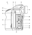
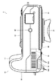
- FIG. 4 is a right side view of the camera body.
- FIG. 5 is a left side view of the camera body.
- the camera body 10 is configured to be portable and has a grip 11 at one end in the lateral direction (left end in FIG. 2).
- a lens mount 12 is provided on the front surface of the camera body 10.
- the interchangeable lens 2 is attached to the lens mount 12.
- a top display monitor 13 is a display unit that mainly displays camera setting information (shutter speed, aperture value, sensitivity, etc.).
- the top display monitor 13 is composed of a liquid crystal display, an organic EL display (Organic Electroluminescence display), and the like.
- the shutter speed dial 14 is a dial for setting the shutter speed.
- the metering dial 15 is a dial for setting the metering mode of the camera.
- the sensitivity dial 17 is a dial for setting the sensitivity.
- the shooting mode dial 18 is a dial for setting a shooting mode.
- the shooting mode dial 18 switches between a mode for shooting a still image (still image shooting mode) and a mode for shooting a moving image (moving image shooting mode).
- a shutter button 19 a power lever 20, a command dial 21, and the like are provided on the upper part of the grip 11.
- the power lever 20 is a lever that turns on and off the power of the digital camera 1.
- the rear surface of the camera body 10 is provided with a rear display monitor 22, a finder (electronic viewfinder) 23, and various operation buttons.
- the rear display monitor 22 is composed of a liquid crystal display, an organic EL display (Organic Electroluminescence display), and the like.
- a terminal cover 24 that can be opened and closed is provided on the right side surface of the camera body 10.
- the terminal cover 24 is attached to the camera body 10 so as to be openable and closable via a hinge (not shown).
- the terminal cover 24 is selectively locked and unlocked in a closed state by a locking mechanism (not shown).
- a terminal portion is provided inside the terminal cover 24.
- the terminal portion includes a power input terminal 25, a video output terminal 26, a USB (Universal Serial Bus) terminal 27, and a microphone terminal 28.
- the power input terminal 25 is connected to a commercial power source (alternating current) via an AC adapter.
- the commercial power supply is an example of an external power supply.
- the power input terminal 25 is an example of an external power supply connection unit.
- a battery cover 30 that can be opened and closed is provided on the left side surface of the camera body 10.
- the battery cover 30 is attached to the camera body 10 so as to be openable and closable via a hinge (not shown).
- the battery cover 30 is selectively locked and unlocked in a closed state by a locking mechanism (not shown).
- a battery insertion slot 32 and a memory card slot 33 are provided inside the battery cover 30.
- the battery insertion port 32 is an insertion port for the battery 200 into the battery chamber 34.
- the battery chamber 34 is provided inside the camera body 10.
- the memory card slot 33 is a loading unit for the memory card 210.
- the battery insertion slot 32 and the memory card slot 33 are opened and closed by the battery cover 30.
- the battery cover 30 is an example of a lid that opens and closes the battery insertion slot 32.
- the main heat source for digital cameras is the image processing unit.
- the amount of heat generated increases when shooting continuously for a long time.
- the image processing unit is composed of a circuit by LSI (Large Scale Integration). Therefore, when the image processing unit is composed of an LSI, it is desirable to dissipate the heat of the LSI and keep the circuit at a relatively low temperature.
- LSI Large Scale Integration
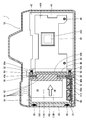
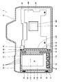
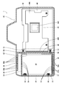
- FIG. 6 is a diagram showing a schematic configuration inside the camera body. This figure corresponds to the 6-6 cross section of FIG. Note that FIG. 6 mainly illustrates only the configuration related to heat dissipation. Further, FIG. 6 shows a state in which the battery 200 is loaded in the battery chamber 34.
- the camera body 10 has an LSI 40 as a heat source inside.
- the LSI 40 is mounted on the camera board 42.
- the camera board 42 is fixed to a frame (not shown) provided on the camera body 10 and arranged at a predetermined position in the camera body.
- the camera substrate 42 fixed to the frame is arranged orthogonal to the shooting optical axis.
- a first sheet metal 44 for heat dissipation is attached to the camera board 42.
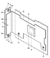
- FIG. 7 is a perspective view showing a schematic configuration of the first sheet metal.
- the first sheet metal 44 has a first sheet metal main body 44A and a first sheet metal contact portion 44B formed by bending one end of the first sheet metal main body 44A at a right angle.
- the first sheet metal 44 is made of a metal such as aluminum, iron, or copper having good heat transfer characteristics.
- the first sheet metal 44 is an example of the first heat transfer member.
- the first sheet metal body 44A is fixed with screws 46 and attached to a specified position on the camera board 42.
- the first sheet metal main body 44A has an LSI contact portion 44C corresponding to the position of the LSI 40.
- the LSI contact portion 44C is a portion that contacts the LSI 40 when the first sheet metal main body portion 44A is attached to the camera substrate 42.
- the LSI contact portion 44C is configured as a recess having a shape corresponding to the outer shape of the LSI 40.
- the LSI 40 may be configured to be brought into contact with the LSI contact portion 44C via a heat conductive sheet (including a sheet-shaped heat conductive gel, a heat conductive pad, etc.).
- a heat conductive sheet including a sheet-shaped heat conductive gel, a heat conductive pad, etc.
- the first sheet metal contact portion 44B has a rectangular flat plate shape.
- the first sheet metal contact portion 44B is arranged at a predetermined position in the camera body by attaching the first sheet metal main body portion 44A to the camera substrate 42, and is arranged perpendicular to the camera substrate 42.
- the LSI 40 When the LSI 40 generates heat, the heat is transferred to the first sheet metal contact portion 44B via the first sheet metal main body portion 44A.
- a second sheet metal 48 is provided inside the camera body 10.
- the second sheet metal 48 is provided so as to be movable back and forth with respect to the first sheet metal contact portion 44B.
- the second sheet metal 48 is made of a metal such as aluminum, iron, or copper having good heat transfer characteristics.
- the second sheet metal 48 is an example of the second heat transfer member.
- the second sheet metal 48 has a rectangular flat plate shape and is arranged so as to face the first sheet metal contact portion 44B.
- the surface of the second sheet metal 48 facing the first sheet metal contact portion 44B functions as a contact portion with the first sheet metal contact portion 44B. Further, in the first sheet metal contact portion 44B, the surface facing the second sheet metal 48 functions as a contact portion with the second sheet metal 48.
- the second sheet metal 48 is movably provided by being guided by a pair of guide rods 50.
- the guide rod 50 is an example of a guide rail.
- the pair of guide rods 50 are attached to the outer wall surface (partition plate) of the battery chamber 34.
- the guide rod 50 attached to the outer wall surface of the battery chamber 34 is arranged along the camera board 42.
- the second sheet metal 48 is provided with a guide hole 48A through which the guide rod 50 is passed.
- the second sheet metal 48 is attached to the guide rod 50 by passing the guide rod 50 through the guide hole 48A, and is held movably along the guide rod 50.
- the second sheet metal 48 attached to the guide rod 50 moves back and forth with respect to the first sheet metal contact portion 44B by moving along the guide rod 50.
- the guide rod 50 is provided with a spring (coil spring) 52.
- a spring coil spring
- One end of the spring 52 abuts on the second sheet metal 48, and the other end abuts on the spring stopper 50A provided at the tip of the guide rod 50.
- the second sheet metal 48 is urged by the spring 52 in a direction away from the first sheet metal contact portion 44B.
- the spring 52 is an example of an urging member.
- a mechanism for moving the second sheet metal 48 forward and backward using the spring 52 is an example of a drive mechanism.
- a battery chamber 34 is provided inside the camera body 10.
- the battery chamber 34 is a space for accommodating the battery 200.
- the battery chamber 34 has a shape corresponding to the outer shape of the battery 200.
- the battery 200 of the digital camera 1 of the present embodiment has a rectangular parallelepiped shape. Therefore, the battery chamber 34 also has a rectangular parallelepiped shape.
- the battery chamber 34 is surrounded by a partition plate 54 and is provided inside the camera body 10.
- the battery chamber 34 has a battery insertion port 32.
- the battery insertion port 32 is provided at a position covered by the battery cover 30. Therefore, the battery insertion port 32 is opened and closed by the battery cover 30.
- a first contact 56 and a second contact 58 are provided inside the battery chamber 34.
- the first contact 56 is a contact for the battery 200.
- the second contact 58 is a contact for the radiator 100.
- the contact 200A provided with the battery 200 is connected to the first contact 56.
- the digital camera 1 is powered by the battery 200 via the first contact 56.
- the contact 100A provided in the radiator 100 is connected to the second contact 58.
- the radiator 100 is supplied with power from the camera body side via the second contact 58.
- a pressing spring 60 is provided inside the battery cover 30.
- the pressing spring 60 urges the battery 200 loaded in the battery chamber 34 along the insertion direction.
- the direction indicated by the arrow IN is the insertion direction of the battery 200.
- the battery 200 is inserted laterally toward the inside of the camera body 10. This direction is orthogonal to the shooting optical axis.
- the guide rod 50 is arranged along the insertion direction of the battery 200. Therefore, the second contact 58 also moves along the insertion direction of the battery 200.
- the battery chamber 34 has a rectangular opening 62 at the end (right end in FIG. 6) in the insertion direction of the battery 200. As shown in FIG. 6, when the battery 200 is loaded in the battery chamber 34, the opening 62 is closed by the second sheet metal 48. Even when nothing is loaded in the battery chamber 34, the opening 62 is closed by the second sheet metal 48. The second sheet metal 48 is urged by the spring 52 and comes into contact with the outer wall surface of the battery chamber 34 to close the opening 62.
- the position where the second sheet metal 48 comes into contact with the first sheet metal contact portion 44B is set as the first position. Further, the position where the second sheet metal 48 closes the opening 62 is set as the second position. The second sheet metal 48 is in contact with the first sheet metal 44 when it is located at the first position, and is separated from the first sheet metal 44 when it is located at the second position.
- the battery chamber 34 has a plurality of upper ventilation holes 64 on the upper surface thereof. Further, the battery chamber 34 has a plurality of lower vent holes 66 on the lower surface portion.
- the radiator 100 is loaded in the battery chamber 34 to dissipate heat inside the camera body 10. More specifically, the heat dissipation of the LSI 40, which is a heat source, is promoted to dissipate heat inside the camera body 10.
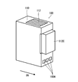
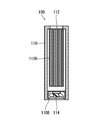
- FIG. 8 is a perspective view showing the external configuration of the radiator.
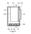
- FIG. 9 is a cross-sectional view showing the internal structure of the radiator.
- FIG. 10 is a cross-sectional view taken along the line 10-10 of FIG.
- the radiator 100 includes a housing 110, a heat sink 112, and a heat radiating fan 114.
- the housing 110 constitutes the housing of the radiator 100.
- the housing 110 has an outer shape corresponding to the outer shape of the battery 200. Therefore, the housing 110 can be loaded into the battery chamber 34 with the battery cover 30 closed.
- the heat sink 112 is housed inside the housing 110, and a part of the heat sink 112 is exposed from the housing 110.
- the heat sink 112 is an example of a heat radiating member, and has a base portion 112A, a fin portion 112B, and a protruding portion 112C.
- the base portion 112A has a rectangular flat plate shape.
- the heat sink 112 is attached to the housing 110 by screwing the base portion 112A to the housing 110 with screws (not shown).
- the fin portion 112B is composed of a plurality of plates extending from the base portion 112A.
- the plates constituting the fin portion 112B are arranged along the insertion direction IN of the radiator 100.
- the protruding portion 112C is an exposed portion of the heat sink 112, and is provided so as to project from the housing 110.
- the housing 110 has a tip opening 110A on the end surface of the tip of the insertion direction IN into the battery chamber 34.
- the projecting portion 112C is provided so as to project from the tip opening 110A along the insertion direction IN.
- the protrusion 112C has a shape through which the opening 62 provided in the battery chamber 34 can be inserted.
- the end face of the protruding portion 112C is formed of a flat surface and is arranged orthogonal to the insertion direction IN.
- the end face of the protruding portion 112C functions as a contact portion with the second sheet metal 48, and is arranged so as to face the second sheet metal 48 when the radiator 100 is loaded into the battery chamber 34.
- the heat radiating fan 114 is arranged inside the housing 110, and discharges the heat accumulated in the heat sink 112 to the outside of the camera body 10.
- the heat radiating fan 114 is arranged so as to face the heat radiating port 110B provided on the lower surface of the housing 110.
- the heat radiating fan 114 is driven by a built-in motor to rotate.
- the heat radiating fan 114 is an example of a heat discharging mechanism.
- the electric power for driving the heat dissipation fan 114 is supplied from the camera body side.
- the housing 110 is provided with a contact 100A for power supply.
- the contact 100A is connected to the second contact 58 provided in the battery chamber 34. In this case, the power is supplied to the camera body 10 via the AC adapter.
- the radiator 100 configured as described above has an external shape having a protruding portion at the end in the insertion direction into the battery chamber 34 with respect to the external shape of the battery 200.
- the portion of the heat sink 112 that protrudes from the housing 110 constitutes the protrusion of the radiator 100.
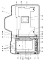
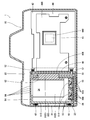
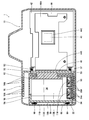
- FIG. 11 is a diagram showing a schematic configuration of the inside of the camera body when a radiator is loaded.
- the radiator 100 can be loaded into the battery chamber 34 with the battery cover 30 closed.
- the radiator 100 loaded in the battery chamber 34 is pressed by the pressing spring 60 provided in the battery cover 30 and urged in the insertion direction IN.
- the protrusion 112C is fitted into the opening 62 of the battery chamber 34.
- the protruding portion 112C fitted in the opening 62 abuts on the second sheet metal 48 and moves the second sheet metal 48 against the urging force of the spring 52.
- the second sheet metal 48 pushed by the projecting portion 112C abuts on the first sheet metal contact portion 44B and stops.
- the first sheet metal 44 and the heat sink 112 are thermally connected via the second sheet metal 48.
- the heat of the LSI 40 is transferred to the heat sink 112 via the first sheet metal 44 and the second sheet metal 48, and is dissipated through the heat sink 112.
- the contact 100A of the radiator 100 is connected to the second contact 58 provided in the battery chamber 34.
- electric power is supplied to the radiator 100 from the camera body side via the second contact 58.
- the radiator 100 rotates. This promotes heat dissipation by the heat sink 112.
- the digital camera 1 of the present embodiment can dissipate heat inside the camera body 10 as needed.
- the radiator 100 is loaded into the battery chamber 34 instead of the battery 200.
- the situation where heat dissipation is required is, for example, the case of continuously shooting high-quality moving images for a long time.
- the amount of heat generated by the LSI 40 which is the image processing unit, increases. Therefore, when shooting a high-quality moving image, the radiator 100 is loaded in the battery chamber 34, and the heat inside the camera body 10 is dissipated to the outside.
- the heat dissipation function of the digital camera 1 is turned on by loading the radiator 100 into the battery chamber 34.
- the power supply is switched to an external power supply (power supply from the AC adapter). In this case, connect the AC adapter to the power input terminal 25.
- FIG. 12 is a diagram illustrating the operation of switching the heat dissipation function on and off.
- FIG. (A) shows a state in which the heat dissipation function is off.
- FIG. (B) shows a state in which the heat dissipation function is on.
- the heat dissipation function is turned off.
- the second sheet metal 48 is separated from the first sheet metal contact portion 44B by the urging force of the spring 52. As a result, the heat dissipation path to the battery side is cut off.
- the amount of heat generated by the LSI 40 is smaller when shooting a still image than when shooting a moving image. Therefore, when shooting a still image, the battery 200 can be used for shooting.
- the second sheet metal 48 separated from the first sheet metal contact portion 44B contacts the outer wall surface of the battery chamber 34 and closes the opening 62. This makes it possible to prevent dust from entering the inside of the camera body 10 from the battery compartment side.
- the radiator 100 when the radiator 100 is loaded in the battery chamber 34, the heat dissipation function is turned on.
- the radiator 100 can be loaded into the battery chamber 34 with the battery cover 30 closed.
- the protrusion of the radiator 100 presses the second sheet metal 48 against the urging force of the spring 52, and the second sheet metal Move 48.
- the moved second sheet metal 48 comes into contact with the first sheet metal contact portion 44B and stops.
- the second sheet metal 48 is pushed by the protruding portion 112C and comes into contact with the first sheet metal contact portion 44B, the first sheet metal 44 and the heat sink 112 are thermally connected via the second sheet metal 48.
- a heat dissipation path from the first sheet metal 44 to the heat sink 112 is formed. Further, this promotes heat dissipation, and heat inside the camera body 10 is dissipated to the outside.
- the contact 100A provided in the radiator 100 is connected to the second contact 58.
- electric power is supplied from the camera body 10 to the radiator 100, and the heat radiating fan 114 operates.
- heat radiating is further promoted.
- the heat inside the camera can be dissipated to the outside as needed.
- the radiator 100 is loaded in the battery chamber 34 instead of the battery 200, so that the camera body itself does not need to be provided with a heat radiating mechanism.
- the camera body 10 can be made smaller and lighter.
- the heat dissipation path to the battery side is cut off, so heat does not flow to the battery side. This makes it possible to prevent the life of the battery 200 from being shortened.
- [Modification example] (1) Relationship of Thermal Conductivity of First Sheet Metal and Second Sheet Metal It is preferable to set the relationship of thermal conductivity of the first sheet metal 44 and the second sheet metal 48 as follows. That is, the thermal conductivity of the second sheet metal 48 is set higher than the thermal conductivity of the first sheet metal 44. As a result, more heat flows toward the radiator 100, and the heat generated from the heat source can be efficiently dissipated to the outside. In addition to this, since a large amount of heat flows to the radiator side, the heat flowing to the exterior of the camera body 10 (particularly, the exterior on the back side) is reduced, and the temperature information of the exterior can be suppressed. In order to have such a thermal conductivity relationship, for example, the first sheet metal 44 is made of aluminum and the second sheet metal 48 is made of a body.
- the heat sink 112 is set to have a thermal conductivity equal to or higher than that of the second sheet metal 48.
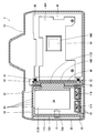
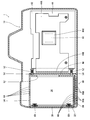
- FIG. 13 is a diagram showing a schematic configuration of the inside of the camera body when the second sheet metal is provided with the heat conductive sheet.
- the second sheet metal 48 is provided with a heat conductive sheet 70 on a surface (contact portion) with which the protrusion (projection portion of the heat sink 112) of the radiator 100 abuts.
- the heat conductive sheet 70 is composed of a sheet-shaped heat conductive gel. When the radiator 100 is loaded into the battery chamber 34, the protruding portion is brought into contact with the second sheet metal 48 via the heat conductive sheet 70.
- the heat conductive sheet 70 is an example of the third heat transfer member.
- the heat conductive sheet is provided on the second sheet metal side
- the heat conductive sheet may be provided on the radiator side.
- a heat conductive sheet is attached to the end face of the protrusion.
- the second sheet metal 48 and the first sheet metal contact portion 44B can be brought into contact with each other via a heat conductive sheet.
- a heat conductive sheet is provided at at least one of the contact portions of the second sheet metal 48 and the first sheet metal contact portion 44B.
- the battery 200 and the radiator 100 loaded in the battery chamber 34 are pressed and held in the insertion direction by the pressing spring 60 provided in the battery cover 30.
- the configuration for holding the battery 200 and the radiator 100 loaded in the battery chamber 34 is not limited to this.
- FIG. 14 is a diagram showing another example of the holding mechanism of the battery and the radiator.
- the battery insertion port 32 has a battery holding claw 72, and the battery holding claw 72 holds the battery 200 and the radiator 100 loaded in the battery chamber 34.
- the battery holding claw 72 swings between the locked position and the unlocked position with the shaft 72A as the swing center. At the locked position, the claw portion at the tip of the battery holding claw 72 projects into the battery insertion port 32 and engages with the battery 200 and the radiator 100 loaded in the battery chamber 34. Further, in the unlocked position of the battery holding claw 72, the claw portion at the tip thereof is compared with the battery insertion port 32, and the battery 200 and the radiator 100 loaded in the battery chamber 34 can be taken out.
- the battery holding claw 72 is urged toward the locked position by a spring (not shown).
- the radiator 100 can be used with the battery cover 30 open.
- the heat radiating fan 114 is configured to exhaust air toward the battery insertion port 32.
- first contact 56 and the second contact 58 are provided inside the battery chamber 34, but the configuration and layout of the first contact 56 and the second contact 58 are different. It is not limited to this.
- FIG. 15 is a diagram showing another example of the first contact and the second contact.
- the first contact 76 and the second contact 78 are provided on the battery cover 30.
- the first contact 76 and the second contact 78 have a spring property, and urge the battery 200 and the radiator 100 loaded in the battery chamber 34 in the insertion direction IN.
- the functions of the first contact 76 and the second contact 78 are the same as those of the first contact 56 and the second contact 58 of the above embodiment. That is, the first contact 76 is a contact for the battery 200, and the second contact 78 is a contact for the radiator 100.
- the battery 200 is provided with a contact at a position corresponding to the first contact 76.
- the heat radiating fan 114 is provided with a contact at a position corresponding to the second contact 78.
- both the first contact and the second contact are provided in the battery cover 30, but only one of them may be provided in the battery cover 30.
- the battery cover 30 may be provided with only the second contact.
- the second sheet metal 48 is moved by using the spring 52, but the mechanism (drive mechanism) for moving the second sheet metal 48 is the same. It is not limited.
- FIG. 16 is a diagram showing another example of the drive mechanism.
- the second sheet metal 48 is moved by electromagnetic force.
- an electromagnet 80 capable of switching magnetic poles is provided inside the camera body 10.
- the electromagnet 80 is an example of an actuator.
- the electromagnet 80 is arranged at the tip of the guide rod 50.
- the second sheet metal 48 is provided with a permanent magnet 82.
- the permanent magnet 82 has a ring shape and is arranged coaxially with the hole through which the guide rod 50 is inserted.
- the drive of the electromagnet 80 is controlled by the control unit of the digital camera 1.
- the control unit of the digital camera 1 controls the drive of the electromagnet 80 according to the state in which the battery 200 is loaded in the battery chamber 34. Specifically, when the battery 200 is loaded, the electromagnet 80 is driven so that a repulsive force is generated between the battery 200 and the permanent magnet 82. On the other hand, when the battery 200 is not loaded, the electromagnet 80 is driven so that an attractive force is generated between the battery 200 and the permanent magnet 82. Whether or not the battery 200 is loaded in the battery chamber 34 is determined by the presence or absence of power supply from the battery 200.
- the control unit is composed of, for example, a processor.
- the processor functions as a control unit of the digital camera 1 by executing a predetermined control program.
- FIG. 17 is a diagram showing an operating state of the electromagnet when the battery is loaded.
- FIG. 18 is a diagram showing an operating state of the electromagnet when a radiator is loaded.
- the electromagnet 80 is driven so that a repulsive force is generated between the battery chamber 34 and the permanent magnet 82.
- the second sheet metal 48 is separated from the first sheet metal contact portion 44B and comes into contact with the outer wall surface of the battery chamber 34.
- the opening 62 of the battery chamber 34 is closed by the second sheet metal 48. Further, this cuts off the heat dissipation path from the first sheet metal 44 to the heat sink 112.
- the electromagnet 80 When the battery 200 is not loaded, the electromagnet 80 is driven so that an attractive force is generated between the battery 200 and the permanent magnet 82. Therefore, when the radiator 100 is loaded, the electromagnet 80 is driven so that an attractive force is generated between the radiator 100 and the permanent magnet 82. As a result, as shown in FIG. 18, the second sheet metal 48 comes into contact with the first sheet metal contact portion 44B. As a result, a heat dissipation path is formed between the first sheet metal 44 and the heat sink 112.
- the second sheet metal 48 may be configured to be moved by using an actuator such as an electromagnet.
- an actuator such as an electromagnet.
- a motor including a linear motor or the like can be used as the actuator.
- the drive of the electromagnet 80 is switched depending on whether or not the battery 200 is loaded, but the drive of the electromagnet 80 may be switched according to other determination criteria.
- the drive of the electromagnet 80 may be switched depending on whether or not an external power source is supplied.
- the drive of the electromagnet 80 may be switched according to an instruction from the user.
- the drive of the electromagnet 80 may be switched according to the switching of the shooting mode (moving image shooting mode and still image shooting mode).
- the digital camera of the present embodiment is different from the digital camera 1 of the first embodiment in that the camera body is provided with a heat radiating portion. In the following, only the differences from the digital camera of the first embodiment will be described.
- FIG. 19 is a diagram showing a schematic configuration inside the camera body.
- the digital camera of the present embodiment has a heat radiating portion 90 on the bottom surface of the camera body 10.
- the heat radiating unit 90 dissipates the heat inside the camera to the outside.
- FIG. 20 is a bottom view of the camera body.
- the heat radiating portion 90 is composed of a plurality of heat radiating slits 90A.
- the heat radiating slits 90A are arranged at regular intervals in one direction.
- the direction in which the heat dissipation slit 90A is arranged is the same as the insertion direction of the battery 200.
- the heat dissipation slit 90A is an example of a heat dissipation hole.
- reference numeral 92 is a tripod hole.
- the heat radiating portion 90 is preferably arranged in an area that is vacant when fixed by a tripod (a region that is not blocked by the tripod). Therefore, it is preferable that the heat radiating portion 90 is arranged at a position away from the tripod hole 92. Further, it is preferable that the heat radiating unit 90 is provided in a vacant area (a region that is not blocked by a hand) when the camera body 10 is gripped by hand (when gripped for photographing). The bottom surface of the camera body 10 is not covered by the hand even when it is gripped by the hand.
- a slit plate 94 for opening and closing the heat dissipation slit 90A is provided inside the camera body 10.
- the slit plate 94 is an example of a heat radiating hole opening / closing portion.
- the slit plate 94 has a rectangular flat plate shape.
- the slit plate 94 is integrally provided with the second sheet metal 48. Specifically, a part of the second sheet metal 48 is bent to form the slit plate 94. In the present embodiment, the lower portion of the second sheet metal 48 is bent at a right angle to form the slit plate 94.
- the slit plate 94 is provided with a plurality of ventilation slits 94A.
- the ventilation slit 94A has a width narrower than that of the heat dissipation slit 90A.
- the ventilation slits 94A are arranged at the same intervals as the heat dissipation slits 90A.
- the slit plate 94 moves in conjunction with the second sheet metal 48 to open and close the heat dissipation slit 90A.
- 21 and 22 are diagrams showing the relationship between the movement of the slit plate and the opening and closing of the heat radiating slit.
- FIG. 21 shows a state in which the heat dissipation slit 90A is opened.
- FIG. 22 shows a state in which the heat dissipation slit 90A is closed.
- the heat dissipation slit 90A is opened when the second sheet metal 48 is moved to a position (first position) where the first sheet metal contact portion 44B is in contact with the second sheet metal 48.
- each ventilation slit 94A provided in the slit plate 94 is placed on the heat radiating slit 90A when the second sheet metal 48 is located at the position (first position) where the second sheet metal 48 abuts on the first sheet metal contact portion 44B.
- the heat dissipation slit 90A is opened, and the inside and the outside of the camera body 10 are communicated with each other.
- each ventilation slit 94A provided in the slit plate 94 is adjacent to the heat dissipation slits when the second sheet metal 48 is located at a position (second position) for closing the opening 62 of the battery chamber 34. It is located in the middle position of 90A. As a result, each heat dissipation slit 90A is closed by the slit plate 94.
- FIG. 23 and 24 are views showing the operating state of the slit plate.
- FIG. 23 shows the operating state of the slit plate when the radiator is loaded in the battery compartment.
- FIG. 24 shows the operating state of the slit plate when the battery is loaded in the battery compartment.
- the protrusion of the radiator 100 presses the second sheet metal 48, and the first sheet metal contact portion. It comes into contact with 44B and stops. As a result, a heat dissipation path from the first sheet metal 44 to the heat sink 112 is formed, and the heat dissipation function is turned on.
- each ventilation slit 94A provided in the slit plate 94 is placed on the heat dissipation slit 90A provided in the camera body 10. It is located in (see FIG. 21). As a result, the heat dissipation slit 90A is opened.
- the position where the second sheet metal 48 closes the opening 62 of the battery chamber 34 by the urging force of the spring 52 (the first position). Move to 2 positions). As a result, the second sheet metal 48 is separated from the first sheet metal 44. When the second sheet metal 48 is separated from the first sheet metal 44, the heat dissipation path from the first sheet metal 44 to the heat sink 112 is cut off, and the heat dissipation function is turned off.
- each ventilation slit 94A provided in the slit plate 94 is between the heat dissipation slits 90A provided in the camera body 10. (See FIG. 22). As a result, the heat dissipation slit 90A is closed.
- the heat dissipation slit 90A provided in the camera body 10 is opened and closed in conjunction with the on / off of the heat dissipation function (insertion / removal of the radiator 100), and is opened only when the heat dissipation function is turned on. That is, it is opened only when the radiator 100 is loaded.
- the heat dissipation function is opened when the heat dissipation function is turned on, the heat dissipation efficiency can be further improved.
- FIG. 25 is a diagram showing another example of the heat radiating unit.
- the camera body 10 of this example is provided with heat radiating portions at two locations, a bottom surface portion and an upper surface portion.
- a lower heat radiating portion 95 is provided on the bottom surface of the camera body 10.
- An upper heat radiating portion 96 is provided on the upper surface portion of the camera body 10. The lower heat radiating portion 95 and the upper heat radiating portion 96 are arranged on the bottom surface portion and the upper surface portion of the camera body 10 with the battery chamber 34 interposed therebetween.
- the lower heat radiating unit 95 and the upper heat radiating unit 96 are composed of a plurality of heat radiating slits 95A and 96A, respectively.
- the heat radiating slits 95A and 96A are arranged at regular intervals in one direction.
- the direction in which the heat dissipation slits 95A and 96A are arranged is the same as the insertion direction of the battery 200.
- the heat dissipation slits 95A and 96A are examples of heat dissipation holes.
- a lower slit plate 97 for opening and closing the lower heat radiating portion 95 and an upper slit plate 98 for opening and closing the upper heat radiating portion 96 are provided inside the camera body 10.
- the lower slit plate 97 and the upper slit plate 98 are examples of heat dissipation hole opening / closing portions.
- the lower slit plate 97 and the upper slit plate 98 have a rectangular flat plate shape.
- the lower slit plate 97 and the upper slit plate 98 are integrally provided on the second sheet metal 48. Specifically, a part of the second sheet metal 48 is bent to form the lower slit plate 97 and the upper slit plate 98.
- the lower slit plate 97 and the upper slit plate 98 are provided with a plurality of ventilation slits 97A and 98A.
- the ventilation slits 97A and 98A have a width narrower than that of the heat dissipation slits 95A and 96A.
- the ventilation slits 97A and 98A are arranged at the same intervals as the heat dissipation slits 95A and 96A.
- the lower slit plate 97 and the upper slit plate 98 move in conjunction with the second sheet metal 48 to open and close the heat dissipation slits 95A and 96A of the lower heat dissipation portion 95 and the upper heat dissipation portion 96.
- FIG. 26 and 27 are views showing the operating state of the lower slit plate and the upper slit plate.
- FIG. 26 shows the operating state of the lower slit plate 97 and the upper slit plate 98 when the radiator 100 is loaded in the battery chamber 34.
- FIG. 27 shows the operating state of the lower slit plate 97 and the upper slit plate 98 when the battery 200 is loaded in the battery chamber 34.
- each ventilation slit 97A provided in the lower slit plate 97 is located above the heat dissipation slit 95A of the lower heat dissipation portion 95.
- each ventilation slit 98A provided in the upper slit plate 98 is located below the heat dissipation slit 96A of the upper heat dissipation portion 96.
- each ventilation slit 97A provided in the lower slit plate 97 is located between the heat dissipation slits 95A of the lower heat dissipation portion 95.
- each ventilation slit 98A provided in the upper slit plate 98 is located between the heat dissipation slits 96A of the upper heat dissipation portion 96.
- the heat radiating slit 96A of the upper heat radiating unit 96 functions as an air supply port
- the heat radiating slit 95A of the lower heat radiating unit 95 functions as an exhaust port
- heat radiating portions can be provided at a plurality of locations on the camera body 10.
- FIG. 28 is a diagram showing a schematic configuration inside the camera body.
- the digital camera of this embodiment is provided with a battery insertion slot 32 on the bottom surface of the camera body 10.
- Other points are the same as those of the digital camera of the first or second embodiment. Therefore, members having the same or similar functions as the digital camera of the first or second embodiment are designated by the same reference numerals, and the description thereof will be omitted.
- the battery 200 and the radiator 100 are inserted directly upward from the battery insertion port 32 provided on the bottom surface of the camera body 10. Therefore, the opening 62 provided in the battery chamber 34 is provided in the upper surface portion of the battery chamber 34 (the end portion of the battery 200 in the insertion direction IN).
- the radiator 100 is provided with a protruding portion (protruding portion 112C of the heat sink 112) on the upper surface portion (upper surface portion when loaded in the battery chamber 34) corresponding to the opening 62 of the battery chamber 34 (see FIG. 30). ..
- FIG. 29 is a diagram showing the internal state of the camera body when the battery is loaded in the battery compartment.
- FIG. 30 is a diagram showing the internal state of the camera body when the radiator is loaded in the battery compartment.
- the second sheet metal 48 is pressed by the urging force of the spring 52 and comes into contact with the outer wall surface of the battery chamber 34. As a result, the opening 62 of the battery chamber 34 is closed by the second sheet metal 48. Further, when the second sheet metal 48 moves to a position (second position) for closing the opening 62, the second sheet metal 48 and the first sheet metal contact portion 44B are separated from each other. As a result, the heat dissipation path to the battery side is cut off, and the heat dissipation function is turned off.
- each ventilation slit 94A provided in the slit plate 94 is located between the heat dissipation slits 90A of the heat dissipation portion 90. As a result, the heat radiating slit 90A is closed and the heat radiating portion 90 is closed.
- the second sheet metal 48 is pushed by the protruding portion of the radiator 100 and comes into contact with the first sheet metal contact portion 44B.
- the heat sink 112 and the first sheet metal 44 are thermally connected via the second sheet metal 48.
- a heat dissipation path from the first sheet metal 44 to the heat sink 112 is formed, and the heat dissipation function is turned on.
- each ventilation slit 94A provided in the slit plate 94 is placed on the heat dissipation slit 90A of the heat dissipation portion 90.
- the heat dissipation slit 90A of the heat dissipation unit 90 is opened.
- the battery 200 and the radiator 100 can be inserted from the bottom surface of the camera body 10.
- the radiator 100 and the camera body 10 are configured according to the insertion direction of the battery 200.
- the heat radiating portion is provided on the side surface portion of the camera body 10, but the heat radiating portion may be provided on the upper surface portion, the back surface portion, or the front portion of the camera body 10. In particular, it is preferable that the heat radiating portion is provided in a vacant area when gripped by hand.
- the radiator is provided with a fan as a heat exhaust mechanism, but the heat exhaust mechanism does not necessarily have to be provided.
- the configuration of the heat exhaust mechanism is not limited to the fan, and other mechanisms may be provided. Further, the radiator may be provided with a thermoelectric element such as a Pelche element and / or a so-called water-cooled cooling mechanism in addition to the fan or instead of the fan.
- a thermoelectric element such as a Pelche element and / or a so-called water-cooled cooling mechanism in addition to the fan or instead of the fan.
- the drive of the radiator may be controlled on the camera body side.
- a temperature sensor is installed in the camera body to detect the temperature inside the camera body or the temperature of the heat source.
- the control unit of the camera controls the drive (rotational speed) of the fan according to the temperature detected by the temperature sensor. As a result, the fan can be driven more appropriately.
- the camera may have a function of notifying the replacement with a radiator.
- the loading of the radiator may be notified.
- the loading of the radiator may be notified when the moving image shooting mode is set and the battery is loaded.
- the notification can be made, for example, by displaying a message prompting the user to load the radiator on the top display monitor 13 and / or the rear display monitor 22.
- the configuration may be such that the temperature inside the camera body or the heat source is detected, and when the temperature exceeds the threshold value, the replacement with the radiator is notified.
- the commercial power source is used as the external power source, but the external power source is not limited to this.
- a so-called mobile battery can also be used as an external power source.
- Control unit After manufacturing the CPU (Central Processing Unit), FPGA (Field Programmable Gate Array), etc., which are general-purpose processors that execute software (programs) and function as various processing units, are used as the processors that make up the control unit of the camera.
- Dedicated processor with a circuit configuration designed exclusively for executing specific processing such as Programmable Logic Device (PLD), which is a processor whose circuit configuration can be changed, and ASIC (Application Specific Integrated Circuit). Includes electrical circuits and the like.
- PLD Programmable Logic Device
- ASIC Application Specific Integrated Circuit
- One processing unit may be composed of one of these various processors, or may be composed of two or more processors of the same type or different types (for example, a plurality of FPGAs or a combination of a CPU and an FPGA). You may. Further, a plurality of processing units may be configured by one processor. As an example of configuring a plurality of processing units with one processor, first, one processor is configured by a combination of one or more CPUs and software, as represented by a computer such as a client or a server. There is a form in which a processor functions as a plurality of processing units.
- SoC System On Chip
- a processor that realizes the functions of the entire system including a plurality of processing units with one IC (Integrated Circuit) chip is used.
- the various processing units are configured by using one or more of the above-mentioned various processors as a hardware-like structure.
- the hardware structure of these various processors is, more specifically, an electric circuit that combines circuit elements such as semiconductor elements.
Landscapes
- Engineering & Computer Science (AREA)
- Aviation & Aerospace Engineering (AREA)
- Physics & Mathematics (AREA)
- General Physics & Mathematics (AREA)
- Multimedia (AREA)
- Signal Processing (AREA)
- Studio Devices (AREA)
- Cameras Adapted For Combination With Other Photographic Or Optical Apparatuses (AREA)
- Camera Bodies And Camera Details Or Accessories (AREA)
Abstract
必要に応じて内部の熱を外部に放熱できるカメラ、カメラボディ及び放熱器を提供する。カメラボディ(10)は、開口部(62)を有するバッテリ室(34)と、熱源に接触して配置される第1板金(44)と、第2板金(48)と、を備える。第2板金(48)は、第1板金(44)に当接する第1位置と、第1板金(44)から離間して開口部(62)を閉塞する第2位置との間を移動自在に設けられ、かつ、バネ(52)によって第2位置に向けて付勢される。バッテリ室(34)に放熱器(100)を装填すると、放熱器(100)に備えられた突出部が、開口部(62)を通って第2板金(48)を押圧し、第1板金(44)に当接する。第2板金(48)が第1板金(44)に当接することにより、第1板金(44)と放熱器(100)とが第2板金(48)を介して熱的に接続される。
Description
本発明は、カメラ、カメラボディ及び放熱器に関する。
カメラボディに放熱用のユニットを装着し、内部の熱を放熱する技術が知られている(たとえば、特許文献1~3等)。
本開示の技術に係る1つの実施形態は、必要に応じて内部の熱を外部に放熱できるカメラ、カメラボディ及び放熱器を提供する。
(1)蓋で開閉されるバッテリ挿入口を有し、かつ、バッテリ挿入口から挿入されるバッテリの挿入方向の端部に開口部を有するバッテリ室と、熱源に接触して配置される第1伝熱部材と、第1伝熱部材に当接する第1位置と第1伝熱部材から離間する第2位置との間を移動し、かつ、第2位置において開口部を閉塞する第2伝熱部材と、第1位置と第2位置との間で第2伝熱部材を移動させる駆動機構と、を備えたカメラボディと、蓋を閉じてバッテリ室に装填可能であり、バッテリ室への挿入方向の端部に突出部を有する放熱器と、を備え、放熱器をバッテリ室に装填すると、突出部が開口部に通って第1位置に位置した第2伝熱部材に当接し、第1伝熱部材と放熱器とが第2伝熱部材を介して熱的に接続される、カメラ。
(2)放熱器は、筐体と、筐体に内蔵され、一部が筐体から突出して突出部を構成する放熱部材と、筐体に内蔵され、放熱部材に蓄積された熱をカメラボディの外へ排出する熱排出機構と、を備える、(1)のカメラ。
(3)熱排出機構は、ファンである、(2)のカメラ。
(4)カメラボディは、外部電源が接続される外部電源接続部を更に備え、熱排出機構は、蓋に備えられた接点から電源が供給される、(2)又は(3)のカメラ。
(5)第2伝熱部材は、第1伝熱部材よりも熱伝導率が高い、(2)から(4)のいずれか一のカメラ。
(6)放熱部材、第1伝熱部材及び第2伝熱部材の少なくとも一つの当接部に、第1伝熱部材及び第2伝熱部材とは異なる第3伝熱部材が備えられる、(2)から(5)のいずれか一のカメラ。
(7)駆動機構は、第2伝熱部材を第2位置に向けて付勢する付勢部材を有し、放熱器をバッテリ室に装填すると、突出部が付勢部材の付勢力に抗して第2伝熱部材を押圧し、第2伝熱部材を第1位置に移動させる、(1)から(6)のいずれか一のカメラ。
(8)駆動機構は、第2伝熱部材の移動をガイドするガイドレールと、第2伝熱部材をガイドレールに沿って移動させるアクチュエータと、を有する、(1)から(6)のいずれか一のカメラ。
(9)アクチュエータは、電磁力により第2伝熱部材を第1位置と第2位置とに移動させる、(8)のカメラ。
(10)カメラボディは、熱を排出する放熱穴を更に備え、第2伝熱部材は、第1位置では放熱穴を開放し、第2位置では放熱穴を閉塞する放熱穴開閉部を更に有する、(1)から(9)のいずれか一のカメラ。
(11)放熱穴は、三脚で固定した場合又は手でグリップした場合に、空いた領域に備えられる、(10)のカメラ。
(12)蓋で開閉されるバッテリ挿入口を有し、かつ、バッテリ挿入口から挿入されるバッテリの挿入方向の端部に開口部を有するバッテリ室と、熱源に接触して配置される第1伝熱部材と、第1伝熱部材に当接する第1位置と第1伝熱部材から離間する第2位置との間を移動し、かつ、第2位置において開口部を閉塞する第2伝熱部材と、第1位置と第2位置との間で第2伝熱部材を移動させる駆動機構と、を備え、蓋を閉じてバッテリ室に装填可能であり、バッテリ室への挿入方向の端部に突出部を有する放熱器をバッテリ室に装填すると、突出部が開口部に通って第1位置に位置した第2伝熱部材に当接し、第1伝熱部材と放熱器とが第2伝熱部材を介して熱的に接続される、カメラボディ。
(13)蓋で開閉されるバッテリ挿入口を有し、かつ、バッテリ挿入口から挿入されるバッテリの挿入方向の端部に開口部を有するバッテリ室と、熱源に接触して配置される第1伝熱部材と、第1伝熱部材に当接する第1位置と第1伝熱部材から離間する第2位置との間を移動し、かつ、第2位置において開口部を閉塞する第2伝熱部材と、第1位置と第2位置との間で第2伝熱部材を移動させる駆動機構と、を備えたカメラボディのバッテリ室に装填されて、熱源を放熱する放熱器であって、蓋を閉じてバッテリ室に装填可能であり、バッテリ室への挿入方向の端部に突出部を有し、バッテリ室に装填されると、突出部が開口部に通って第1位置に位置した第2伝熱部材に当接し、第2伝熱部材を介して第1伝熱部材と熱的に接続される、放熱器。
以下、添付図面に従って本発明の好ましい実施の形態について詳説する。
[第1の実施の形態]
ここでは、本発明をデジタルカメラに適用した場合を例に説明する。
ここでは、本発明をデジタルカメラに適用した場合を例に説明する。
[デジタルカメラにおける発熱の問題点]
まず、デジタルカメラにおける発熱の問題点について説明する。
まず、デジタルカメラにおける発熱の問題点について説明する。
デジタルカメラの多くは、静止画の撮影機能に加えて、動画の撮影機能を有している。動画は、静止画に比して情報量が多い。このため、画像処理の際の消費電力が大きく、長時間連続して撮影していると、カメラ内部の温度が上昇する。カメラ内部の温度上昇は、デジタルカメラの異状動作を招くおそれがある。したがって、動画の撮影機能を備えたデジタルカメラは、放熱機構を備えることが好ましい。しかしながら、デジタルカメラに放熱機構を搭載すると、機器のサイズ及び重量が大きくなるという欠点がある。
本実施の形態のデジタルカメラは、必要に応じて内部の熱を外部に放熱できるデジタルカメラを提供する。
[デジタルカメラの構成]
図1は、デジタルカメラのシステム構成を示す図である。
図1は、デジタルカメラのシステム構成を示す図である。
同図に示すように、本実施の形態のデジタルカメラ1は、レンズ交換式のデジタルカメラであり、交換レンズ2及びカメラボディ10を備える。また、本実施の形態のデジタルカメラ1は、カメラボディ10に装着型の放熱器100を備える。放熱器100は、カメラボディ10の内部で発生する熱を放出するユニットであり、カメラボディ10に装着して使用される。放熱器100は、バッテリ200に代えて、バッテリ室に装着される。
[カメラボディ]
[カメラボディの外部構造]
図2は、カメラボディの正面斜視図である。図3は、カメラボディの背面斜視図である。図4は、カメラボディの右側面図である。図5は、カメラボディの左側面図である。
[カメラボディの外部構造]
図2は、カメラボディの正面斜視図である。図3は、カメラボディの背面斜視図である。図4は、カメラボディの右側面図である。図5は、カメラボディの左側面図である。
カメラボディ10は、携帯可能なサイズで構成され、横方向の一端(図2の左端)にグリップ11が備えられる。
図2に示すように、カメラボディ10の正面には、レンズマウント12が備えられる。交換レンズ2は、このレンズマウント12に装着される。
また、図2に示すように、カメラボディ10の上部(いわゆる軍艦部)には、上面表示モニタ13、シャッタースピードダイヤル14、測光ダイヤル15、ホットシュー16、感度ダイヤル17、撮影モードダイヤル18等が備えられる。上面表示モニタ13は、主としてカメラの設定情報(シャッタ速度、絞り値、感度等)を表示する表示部である。上面表示モニタ13は、液晶ディスプレイ、有機ELディスプレイ(Organic ElectroLuminescence display)等で構成される。シャッタースピードダイヤル14は、シャッタースピードを設定するダイヤルである。測光ダイヤル15は、カメラの測光モードを設定するダイヤルである。感度ダイヤル17は、感度を設定するダイヤルである。撮影モードダイヤル18は、撮影モードを設定するダイヤルである。この撮影モードダイヤル18によって、静止画の撮影を行うモード(静止画撮影モード)と、動画を撮影するモード(動画撮影モード)との切り替えが行われる。
また、図2に示すように、グリップ11の上部には、シャッタボタン19、電源レバー20、コマンドダイヤル21等が備えられる。電源レバー20は、デジタルカメラ1の電源をオン、オフするレバーである。
図3に示すように、カメラボディ10の背面には、背面表示モニタ22、ファインダ(電子ビューファインダ)23、各種操作ボタン類が備えられる。背面表示モニタ22は、液晶ディスプレイ、有機ELディスプレイ(Organic ElectroLuminescence display)等で構成される。
図2に示すように、カメラボディ10の右側面には、開閉可能な端子カバー24が備えられる。端子カバー24は、図示しないヒンジを介して、カメラボディ10に開閉可能に取り付けられる。端子カバー24は、図示しないロック機構によって、閉じられた状態で選択的にロック及びアンロックされる。端子カバー24の内側には、端子部が備えられる。端子部には、図4に示すように、電源入力端子25、映像出力端子26、USB(Universal Serial Bus)端子27、マイク端子28が備えられる。電源入力端子25は、ACアダプタを介して、商用電源(交流)に接続される。商用電源は、外部電源の一例である。電源入力端子25は、外部電源接続部の一例である。デジタルカメラ1は、外部電源に接続された場合、外部電源から供給される電力で作動する。
図3に示すように、カメラボディ10の左側面には、開閉可能なバッテリカバー30が備えられる。バッテリカバー30は、図示しないヒンジを介して、カメラボディ10に開閉可能に取り付けられる。バッテリカバー30は、図示しないロック機構によって、閉じられた状態で選択的にロック及びアンロックされる。バッテリカバー30の内側には、図5に示すように、バッテリ挿入口32及びメモリカードスロット33が備えられる。バッテリ挿入口32は、バッテリ室34へのバッテリ200の挿入口である。バッテリ室34は、カメラボディ10の内部に備えられる。メモリカードスロット33は、メモリカード210の装填部である。バッテリ挿入口32及びメモリカードスロット33は、バッテリカバー30によって開閉される。バッテリカバー30は、バッテリ挿入口32を開閉する蓋の一例である。
[カメラボディの内部構造]
ここでは、放熱に係わる構成についてのみ説明する。
ここでは、放熱に係わる構成についてのみ説明する。
デジタルカメラの主な熱源は画像処理部である。特に、長時間連続して撮影する場合に発熱量が増大する。一般にデジタルカメラでは、画像処理部がLSI(Large Scale Integration)による回路で構成される。したがって、画像処理部がLSIで構成される場合、LSIの熱を放熱して回路を比較的低温に保つことが望ましい。以下、熱源がLSIである場合において、LSIの熱を放熱する場合を例に説明する。
図6は、カメラボディの内部の概略構成を示す図である。同図は、図5の6-6断面に相当する。なお、図6は、主として、放熱に係わる構成についてのみ図示している。また、図6は、バッテリ室34にバッテリ200を装填した状態を示している。
図6に示すように、カメラボディ10は、内部に熱源であるLSI40を有する。LSI40は、カメラ基板42に実装される。カメラ基板42は、カメラボディ10に備えられた図示しないフレームに固定されて、カメラボディ内の規定位置に配置される。フレームに固定されたカメラ基板42は、撮影光軸に対し、直交して配置される。カメラ基板42には、放熱用の第1板金44が取り付けられる。
図7は、第1板金の概略構成を示す斜視図である。
同図に示すように、第1板金44は、第1板金本体部44Aと、第1板金本体部44A一端を直角に折り曲げて形成された第1板金当接部44Bと、を有する。第1板金44は、伝熱特性の良いアルミニウム、鉄、銅などの金属で構成される。第1板金44は、第1伝熱部材の一例である。
第1板金本体部44Aは、ネジ46で固定されて、カメラ基板42上の規定位置に取り付けられる。第1板金本体部44Aは、LSI40の位置に対応して、LSI当接部44Cを有する。LSI当接部44Cは、第1板金本体部44Aをカメラ基板42に取り付けた場合に、LSI40に当接する部位である。LSI当接部44Cは、LSI40の外形に対応した形状の凹部として構成される。第1板金本体部44Aをカメラ基板42に取り付けると、カメラ基板42に備えられたLSI40の表面が、LSI当接部44Cに当接する。これにより、LSI40が発熱すると、その熱が第1板金44に伝達される。
なお、LSI40は、熱伝導シート(シート状熱伝導ゲル、熱伝導パッド等を含む)を介して、LSI当接部44Cに当接させる構成としてもよい。
第1板金当接部44Bは、矩形の平板形状を有する。第1板金当接部44Bは、第1板金本体部44Aがカメラ基板42に取り付けられることにより、カメラボディ内の規定位置に配置され、かつ、カメラ基板42に対し、垂直に配置される。LSI40が発熱すると、その熱が第1板金本体部44Aを介して第1板金当接部44Bに伝達される。
図6に示すように、カメラボディ10の内部には、第2板金48が備えられる。第2板金48は、第1板金当接部44Bに対し、進退移動可能に設けられる。第2板金48は、伝熱特性の良いアルミニウム、鉄、銅などの金属で構成される。第2板金48は、第2伝熱部材の一例である。
第2板金48は、矩形の平板形状を有し、第1板金当接部44Bに対向して配置される。第2板金48は、第1板金当接部44Bと対向する面が、第1板金当接部44Bとの当接部として機能する。また、第1板金当接部44Bは、第2板金48と対向する面が、第2板金48との当接部として機能する。
第2板金48は、一対のガイドロッド50にガイドされて、移動可能に設けられる。ガイドロッド50は、ガイドレールの一例である。一対のガイドロッド50は、バッテリ室34の外壁面(仕切り板)に取り付けられる。バッテリ室34の外壁面に取り付けられたガイドロッド50は、カメラ基板42に沿って配置される。第2板金48には、ガイドロッド50が通されるガイド穴48Aが備えられる。第2板金48は、ガイド穴48Aにガイドロッド50が通されることにより、ガイドロッド50に取り付けられ、かつ、ガイドロッド50に沿って移動可能に保持される。ガイドロッド50に取り付けられた第2板金48は、ガイドロッド50に沿って移動することにより、第1板金当接部44Bに対し進退移動する。
ガイドロッド50には、バネ(コイルバネ)52が備えられる。バネ52は、一端が第2板金48に当接し、他端がガイドロッド50の先端に備えられたバネ止め部50Aに当接する。第2板金48は、このバネ52によって、第1板金当接部44Bから離間する方向に付勢される。バネ52は、付勢部材の一例である。また、バネ52を利用して、第2板金48を進退移動させる機構は、駆動機構の一例である。
図6に示すように、カメラボディ10の内部には、バッテリ室34が備えられる。バッテリ室34は、バッテリ200が収容する空間である。バッテリ室34は、バッテリ200の外形に対応した形状を有する。本実施の形態のデジタルカメラ1のバッテリ200は、図1に示すように、直方体形状を有する。よって、バッテリ室34も直方体形状を有する。
バッテリ室34は、仕切り板54で囲われて、カメラボディ10の内部に備えられる。バッテリ室34は、バッテリ挿入口32を有する。バッテリ挿入口32は、バッテリカバー30で覆われる位置に備えられる。したがって、バッテリ挿入口32は、バッテリカバー30によって開閉される。
バッテリ室34の内部には、第1接点56及び第2接点58が備えられる。第1接点56は、バッテリ200用の接点である。第2接点58は、放熱器100用の接点である。バッテリ200がバッテリ室34に装填されると、バッテリ200の備えられた接点200Aが、第1接点56に接続される。デジタルカメラ1は、第1接点56を介して、バッテリ200から給電される。また、後述するように、放熱器100がバッテリ室34に装填されると、放熱器100に備えられた接点100Aが、第2接点58に接続される。放熱器100は、第2接点58を介して、カメラボディ側から給電される。
バッテリカバー30の内側には、押圧バネ60が備えられる。押圧バネ60は、バッテリ室34に装填されたバッテリ200を挿入方向に沿って付勢する。なお、図6において、矢印INで示す方向が、バッテリ200の挿入方向である。バッテリ200は、カメラボディ10の内部に向けて横方向に挿入される。この方向は、撮影光軸と直交する方向である。ガイドロッド50は、バッテリ200の挿入方向に沿って配置される。したがって、第2接点58もバッテリ200の挿入方向に沿って移動する。
バッテリ室34は、バッテリ200の挿入方向の端部(図6において右端部)に矩形状の開口部62を有する。図6に示すように、バッテリ室34にバッテリ200が装填されている場合、開口部62は、第2板金48によって閉塞される。なお、バッテリ室34に何も装填されていない場合も、開口部62は、第2板金48によって閉塞される。第2板金48は、バネ52に付勢されて、バッテリ室34の外壁面に当接し、開口部62を閉塞する。
なお、第2板金48が、第1板金当接部44Bに当接する位置を第1位置とする。また、第2板金48が、開口部62を閉塞する位置を第2位置とする。第2板金48は、第1位置に位置することで、第1板金44と当接し、第2位置に位置することで、第1板金44と離間する。
バッテリ室34は、上面部に複数の上部通気孔64を有する。また、バッテリ室34は、下面部に複数の下部通気孔66を有する。
[放熱器]
放熱器100は、バッテリ室34に装填されて、カメラボディ10の内部を放熱する。より具体的には、熱源であるLSI40の放熱を促進させて、カメラボディ10の内部を放熱する。
放熱器100は、バッテリ室34に装填されて、カメラボディ10の内部を放熱する。より具体的には、熱源であるLSI40の放熱を促進させて、カメラボディ10の内部を放熱する。
図8は、放熱器の外観構成を示す斜視図である。図9は、放熱器の内部構造を示す断面図である。図10は、図9の10-10断面図である。
図8から図10に示すように、放熱器100は、筐体110、ヒートシンク112及び放熱ファン114を有する。
筐体110は、放熱器100の筐体を構成する。筐体110は、バッテリ200の外形に対応した外形形状を有する。したがって、筐体110は、バッテリカバー30を閉じた状態でバッテリ室34に装填可能である。
ヒートシンク112は、筐体110の内部に収容され、一部が筐体110から露出して設けられる。ヒートシンク112は、放熱部材の一例であり、ベース部112A、フィン部112B及び突出部112Cを有する。
ベース部112Aは、矩形の平板形状を有する。ヒートシンク112は、ベース部112Aが、図示しないネジで筐体110にネジ止めされて、筐体110に取り付けられる。
フィン部112Bは、ベース部112Aから延びる複数枚の板で構成される。フィン部112Bを構成する板は、放熱器100の挿入方向INに沿って配置される。
突出部112Cは、ヒートシンク112の露出部であり、筐体110から突出して設けられる。筐体110は、バッテリ室34への挿入方向INの先端の端面に先端開口部110Aを有する。突出部112Cは、この先端開口部110Aから挿入方向INに沿って突出して設けられる。突出部112Cは、バッテリ室34に備えられた開口部62を挿通可能な形状を有する。突出部112Cの端面は、平面で構成され、挿入方向INと直交して配置される。突出部112Cの端面は、第2板金48との当接部として機能し、放熱器100をバッテリ室34に装填した場合に、第2板金48と対向して配置される。
放熱ファン114は、筐体110の内部に配置され、ヒートシンク112に蓄積された熱をカメラボディ10の外へ排出する。放熱ファン114は、筐体110の下面に備えられた放熱口110Bに面して配置される。放熱ファン114は、内蔵するモータに駆動されて回転する。放熱ファン114は、熱排出機構の一例である。
放熱ファン114を駆動するための電力は、カメラボディ側から供給される。筐体110には、給電用の接点100Aが備えられる。この接点100Aが、放熱器100が、バッテリ室34に装填されると、バッテリ室34に備えられた第2接点58に接続される。なお、この場合、カメラボディ10への電力の供給は、ACアダプタを介して行われる。
以上のように構成される放熱器100は、バッテリ200の外観形状に対し、バッテリ室34への挿入方向の端部に突出部を備えた外観形状となる。なお、ヒートシンク112の突出部112Cが、筐体110から突出する部分が、放熱器100の突出部を構成する。
図11は、放熱器が装填された場合のカメラボディの内部の概略構成を示す図である。
同図に示すように、放熱器100は、バッテリカバー30を閉じた状態でバッテリ室34に装填できる。
バッテリ室34に装填された放熱器100は、バッテリカバー30に備えられた押圧バネ60に押圧されて、挿入方向INに付勢される。
また、バッテリ室34に装填された放熱器100は、突出部112Cが、バッテリ室34の開口部62に嵌入される。開口部62に嵌入された突出部112Cは、第2板金48に当接し、第2板金48をバネ52の付勢力に抗して移動させる。突出部112Cに押された第2板金48は、第1板金当接部44Bに当接して停止する。
第2板金48が、第1板金当接部44Bに当接することで、第1板金44とヒートシンク112とが、第2板金48を介して熱的に接続される。これにより、LSI40の熱が、第1板金44及び第2板金48を介してヒートシンク112に伝熱され、ヒートシンク112を介して放熱される。
また、放熱器100がバッテリ室34に装填されると、放熱器100の接点100Aが、バッテリ室34に備えられた第2接点58に接続される。これにより、第2接点58を介して、カメラボディ側から放熱器100に電力が供給される。放熱器100に電力が供給されることにより、放熱器100が回転する。これにより、ヒートシンク112による放熱が促進される。
[デジタルカメラの作用]
本実施の形態のデジタルカメラ1は、必要に応じてカメラボディ10の内部を放熱できる。カメラボディ10の内部を放熱する場合は、バッテリ200に代えて、放熱器100をバッテリ室34に装填する。
本実施の形態のデジタルカメラ1は、必要に応じてカメラボディ10の内部を放熱できる。カメラボディ10の内部を放熱する場合は、バッテリ200に代えて、放熱器100をバッテリ室34に装填する。
放熱が必要な状況とは、たとえば、高画質な動画を長時間連続して撮影する場合である。この場合、画像処理部であるLSI40の発熱量が増大する。よって、高画質の動画を撮影する場合は、放熱器100をバッテリ室34に装填し、カメラボディ10の内部の熱を外部に放熱する。デジタルカメラ1は、放熱器100をバッテリ室34に装填することで、放熱機能がオンする。放熱器100を使用する場合は、電源を外部電源(ACアダプタからの給電)に切り替える。この場合、電源入力端子25にACアダプタを接続する。
図12は、放熱機能のオン及びオフの切り替わりの動作を説明する図である。同図(A)は、放熱機能がオフの状態を示している。同図(B)は、放熱機能がオンの状態を示している。
図12(A)に示すように、バッテリ室34にバッテリ200が装填されている場合、放熱機能がオフとなる。バッテリ室34にバッテリ200が装填されている場合、第2板金48が、バネ52の付勢力によって、第1板金当接部44Bから離間する。これにより、バッテリ側への放熱経路が絶たれる。
静止画の撮影は、動画の撮影に比べて、LSI40の発熱量が少ない。したがって、静止画を撮影する場合は、バッテリ200を使用して撮影できる。
第1板金当接部44Bから離間した第2板金48は、バッテリ室34の外壁面に当接し、開口部62を閉塞する。これにより、バッテリ室側からカメラボディ10の内部に塵埃が侵入するのを防止できる。
図12(B)に示すように、バッテリ室34に放熱器100が装填されると、放熱機能がオンされる。放熱器100は、バッテリカバー30を閉じた状態でバッテリ室34に装填できる。
バッテリ室34に放熱器100が装填されると、放熱器100の突出部(ヒートシンク112の突出部112C)が、バネ52の付勢力に抗して、第2板金48を押圧し、第2板金48を移動させる。移動した第2板金48は、第1板金当接部44Bに当接して停止する。第2板金48が突出部112C押されて第1板金当接部44Bに当接することにより、第1板金44とヒートシンク112とが、第2板金48を介して熱的に接続される。これにより、第1板金44からヒートシンク112への放熱経路が形成される。また、これにより、放熱が促進され、カメラボディ10の内部の熱が外部に放熱される。
また、バッテリ室34に放熱器100が装填されると、放熱器100に備えられた接点100Aが、第2接点58に接続される。これにより、カメラボディ10から放熱器100に電力が供給され、放熱ファン114が作動する。放熱ファン114が作動することにより、より放熱が促進される。
以上説明したように、本実施の形態のデジタルカメラ1によれば、必要に応じてカメラ内部の熱を外部に放熱できる。カメラボディ10の内部の熱を外部に放熱する場合は、バッテリ200に代えて放熱器100をバッテリ室34に装填する構成なので、カメラボディ自体に放熱機構を備える必要がない。これにより、カメラボディ10を小型かつ軽量化できる。
また、放熱が不要な場合は、バッテリ側への放熱経路が断たれるため、バッテリ側に熱が流れることがない。これにより、バッテリ200の寿命短縮を防止できる。
[変形例]
(1)第1板金及び第2板金の熱伝導率の関係
第1板金44及び第2板金48については、熱伝導率の関係を次のように設定することが好ましい。すなわち、第2板金48の熱伝導率を第1板金44の熱伝導率よりも高く設定する。これにより、より多くの熱が放熱器100の方に流れ、熱源から発生する熱を外部に効率的に放熱できる。これに加え、放熱器側に多くの熱が流れるため、カメラボディ10の外装(特に、背面側の外装)に流れる熱が少なくなり、外装の温度情報を抑制できる。このような熱伝導率の関係にするには、たとえば、第1板金44をアルミニウムで構成し、第2板金48を胴で構成する。
(1)第1板金及び第2板金の熱伝導率の関係
第1板金44及び第2板金48については、熱伝導率の関係を次のように設定することが好ましい。すなわち、第2板金48の熱伝導率を第1板金44の熱伝導率よりも高く設定する。これにより、より多くの熱が放熱器100の方に流れ、熱源から発生する熱を外部に効率的に放熱できる。これに加え、放熱器側に多くの熱が流れるため、カメラボディ10の外装(特に、背面側の外装)に流れる熱が少なくなり、外装の温度情報を抑制できる。このような熱伝導率の関係にするには、たとえば、第1板金44をアルミニウムで構成し、第2板金48を胴で構成する。
なお、ヒートシンク112については、第2板金48の熱伝導率と同じか、それ以上の熱伝導率に設定する。
(2)熱伝導シートを介した接続
上記実施の形態のデジタルカメラ1では、放熱器100を装填した場合に、放熱器100の突出部が、第2板金48に直接接触する構成とされているが、熱伝導シートを介して接触する構成とすることもできる。この場合、シート状熱伝導ゲル及び熱伝導パッド等のクッション性を有する熱伝導シートを介して、当接する構成とすることが好ましい。これにより、密着性を向上できる。
上記実施の形態のデジタルカメラ1では、放熱器100を装填した場合に、放熱器100の突出部が、第2板金48に直接接触する構成とされているが、熱伝導シートを介して接触する構成とすることもできる。この場合、シート状熱伝導ゲル及び熱伝導パッド等のクッション性を有する熱伝導シートを介して、当接する構成とすることが好ましい。これにより、密着性を向上できる。
図13は、第2板金に熱伝導シートを備えた場合のカメラボディの内部の概略構成を示す図である。
同図に示すように、第2板金48は、放熱器100の突出部(ヒートシンク112の突出部)が当接する面(当接部)に熱伝導シート70が備えられている。熱伝導シート70は、シート状熱伝導ゲルで構成される。放熱器100は、バッテリ室34に装填されると、突出部が熱伝導シート70を介して第2板金48に当接される。熱伝導シート70は、第3伝熱部材の一例である。
なお、本例では、第2板金側に熱伝導シートを備えた場合を例に説明したが、放熱器側に熱伝導シートを備えてもよい。この場合、突出部の端面に熱伝導シートが取り付けられる。
第2板金48と第1板金当接部44Bとの間についても同様に、熱伝導シートを介して当接させる構成とすることができる。この場合、第2板金48と第1板金当接部44Bの少なくとも一方の当接部に熱伝導シートが備えられる。
(3)バッテリの保持機構
上記実施の形態では、バッテリ室34に装填されたバッテリ200及び放熱器100をバッテリカバー30に備えられた押圧バネ60で挿入方向に押圧して保持する構成としている。バッテリ室34に装填されたバッテリ200及び放熱器100を保持する構成は、これに限定されるものではない。
上記実施の形態では、バッテリ室34に装填されたバッテリ200及び放熱器100をバッテリカバー30に備えられた押圧バネ60で挿入方向に押圧して保持する構成としている。バッテリ室34に装填されたバッテリ200及び放熱器100を保持する構成は、これに限定されるものではない。
図14は、バッテリ及び放熱器の保持機構の他の一例を示す図である。
同図に示すように、バッテリ挿入口32にバッテリ保持爪72を有し、このバッテリ保持爪72でバッテリ室34に装填されたバッテリ200及び放熱器100を保持する。バッテリ保持爪72は、軸72Aを揺動中心として、ロック位置とアンロック位置との間を揺動する。バッテリ保持爪72は、ロック位置において、先端の爪部が、バッテリ挿入口32に突出し、バッテリ室34に装填されたバッテリ200及び放熱器100に係合する。また、バッテリ保持爪72は、アンロック位置において、先端の爪部がバッテリ挿入口32から対比し、バッテリ室34に装填されたバッテリ200及び放熱器100の取り出しが可能になる。バッテリ保持爪72は、図示しないバネによって、ロック位置に向けて付勢される。
このような保持機構が備えられている場合、バッテリカバー30を開けた状態で放熱器100を使用することもできる。なお、この場合、放熱ファン114は、バッテリ挿入口32に向けて排気する構成とすることが好ましい。
(4)接点の他の例
上記実施の形態では、バッテリ室34の内部に第1接点56及び第2接点58を備えているが、第1接点56及び第2接点58の構成及びレイアウトは、これに限定されるものではない。
上記実施の形態では、バッテリ室34の内部に第1接点56及び第2接点58を備えているが、第1接点56及び第2接点58の構成及びレイアウトは、これに限定されるものではない。
図15は、第1接点及び第2接点の他の一例を示す図である。
同図に示すように、本実施の形態のデジタルカメラは、第1接点76及び第2接点78がバッテリカバー30に備えられる。この第1接点76及び第2接点78は、バネ性を有し、バッテリ室34に装填されたバッテリ200及び放熱器100を挿入方向INに付勢する。
なお、第1接点76及び第2接点78の機能は、上記実施の形態の第1接点56及び第2接点58と同じである。すなわち、第1接点76は、バッテリ200用の接点であり、第2接点78は、放熱器100用の接点である。バッテリ200は、第1接点76に対応する位置に接点が備えられる。また、放熱ファン114は、第2接点78に対応する位置に接点が備えられる。
本例では、第1接点及び第2接点の双方をバッテリカバー30に備える構成としているが、いずれか一方のみをバッテリカバー30に備える構成としてもよい。たとえば、第2接点のみバッテリカバー30に備える構成としてもよい。
(5)駆動機構の他の例
上記実施の形態では、バネ52を利用して、第2板金48を移動させる構成としているが、第2板金48を移動させる機構(駆動機構)は、これに限定されるものではない。
上記実施の形態では、バネ52を利用して、第2板金48を移動させる構成としているが、第2板金48を移動させる機構(駆動機構)は、これに限定されるものではない。
図16は、駆動機構の他の一例を示す図である。
本例では、電磁力により第2板金48を移動させる。図16に示すように、カメラボディ10の内部には、磁極の切り替えが可能な電磁石80が備えられる。電磁石80は、アクチュエータの一例である。電磁石80は、ガイドロッド50の先端部に配置される。一方、第2板金48には、永久磁石82が備えられる。永久磁石82は、リング状の形状を有し、ガイドロッド50が挿通される穴の同軸上に配置される。
電磁石80は、デジタルカメラ1の制御部によって駆動が制御される。デジタルカメラ1の制御部は、バッテリ室34へのバッテリ200の装填状態に応じて、電磁石80の駆動を制御する。具体的には、バッテリ200が装填されている場合は、永久磁石82との間に反発力が発生するように、電磁石80を駆動する。一方、バッテリ200が装填されていない場合は、永久磁石82との間に吸引力が発生するように、電磁石80を駆動する。バッテリ室34にバッテリ200が装填されているか否かは、バッテリ200からの給電の有無によって判別する。制御部は、たとえば、プロセッサで構成される。プロセッサは、所定の制御プログラムを実行することにより、デジタルカメラ1の制御部として機能する。
図17は、バッテリが装填された場合の電磁石の動作状態を示す図である。図18は、放熱器が装填された場合の電磁石の動作状態を示す図である。
上記のように、バッテリ室34にバッテリ200が装填されている場合、永久磁石82との間に反発力が発生するように、電磁石80が駆動される。これにより、図17に示すように、第2板金48が第1板金当接部44Bから離間し、バッテリ室34の外壁面に当接する。これにより、バッテリ室34の開口部62が第2板金48によって閉塞される。また、これにより、第1板金44からヒートシンク112への放熱経路が絶たれる。
バッテリ200が装填されていない場合は、永久磁石82との間に吸引力が発生するように、電磁石80を駆動される。したがって、放熱器100が装填されている場合は、永久磁石82との間に吸引力が発生するように、電磁石80を駆動される。これにより、図18に示すように、第2板金48が第1板金当接部44Bに当接する。これにより、第1板金44とヒートシンク112との間の放熱経路が形成される。
このように、第2板金48は、電磁石等のアクチュエータを用いて移動させる構成としてもよい。アクチュエータには、この他、モータ(リニアモータを含む)等を使用できる。
なお、上記の例では、バッテリ200の装填の有無によって、電磁石80の駆動を切り替える構成としているが、他の判定基準に従って電磁石80の駆動を切り替える構成とすることもできる。たとえば、外部電源の供給の有無に応じて、電磁石80の駆動を切り替える構成としてもよい。また、ユーザからの指示に応じて、電磁石80の駆動を切り替える構成としてもよい。更に、撮影モード(動画撮影モードと静止画撮影モード)の切り替えに応じて、電磁石80の駆動を切り替える構成としてもよい。
[第2の実施の形態]
本実施の形態のデジタルカメラは、カメラボディに放熱部を備える点で上記第1の実施の形態のデジタルカメラ1と相違する。以下においては、第1の実施の形態のデジタルカメラとの相違点についてのみ説明する。
本実施の形態のデジタルカメラは、カメラボディに放熱部を備える点で上記第1の実施の形態のデジタルカメラ1と相違する。以下においては、第1の実施の形態のデジタルカメラとの相違点についてのみ説明する。
[構成]
図19は、カメラボディの内部の概略構成を示す図である。
図19は、カメラボディの内部の概略構成を示す図である。
本実施の形態のデジタルカメラは、カメラボディ10の底面部に放熱部90を有する。放熱部90は、カメラ内部の熱を外部に放熱する。
図20は、カメラボディの底面図である。同図に示すように、放熱部90は、複数の放熱スリット90Aで構成される。放熱スリット90Aは、一方向に一定の間隔で配置される。放熱スリット90Aが配置される方向は、バッテリ200の挿入方向と同じ方向である。放熱スリット90Aは、放熱穴の一例である。
図20において、符号92は三脚穴である。放熱部90は、三脚で固定した場合に空いた領域(三脚で塞がれない領域)に配置することが好ましい。したがって、放熱部90は、三脚穴92から離れた位置に配置することが好ましい。また、放熱部90は、カメラボディ10を手でグリップした場合(撮影のためにグリップした場合)に、空いた領域(手で塞がれない領域)に備えることが好ましい。カメラボディ10の底面部は、手でグリップした場合であっても、手で覆われることはない。
図19に示すように、カメラボディ10の内部には、放熱スリット90Aを開閉するスリット板94が備えられる。スリット板94は、放熱穴開閉部の一例である。スリット板94は、矩形の平板状の形状を有する。スリット板94は、第2板金48に一体的に備えられる。具体的には、第2板金48の一部を折り曲げて、スリット板94が構成される。本実施の形態では、第2板金48の下部を直角に折り曲げて、スリット板94が構成される。スリット板94には、複数の通気スリット94Aが備えられる。通気スリット94Aは、放熱スリット90Aよりも狭い幅で構成される。通気スリット94Aは、放熱スリット90Aと同じ間隔で配置される。
スリット板94は、第2板金48に連動して移動し、放熱スリット90Aを開閉する。図21及び図22は、スリット板の移動と放熱スリットの開閉の関係を示す図である。図21は、放熱スリット90Aが開けられた状態を示している。図22は、放熱スリット90Aが閉じられた状態を示している。
放熱スリット90Aは、第2板金48に第1板金当接部44Bに当接する位置(第1位置)に移動すると、開けられる。図21に示すように、スリット板94に備えられた各通気スリット94Aは、第2板金48が第1板金当接部44Bに当接する位置(第1位置)に位置すると、放熱スリット90A上に位置する。これにより、放熱スリット90Aが開放され、カメラボディ10の内部と外部とが連通される。
また、放熱スリット90Aは、第2板金48がバッテリ室34の開口部62を閉塞する位置(第2位置)に移動すると、閉じられる。図22に示すように、スリット板94に備えられた各通気スリット94Aは、第2板金48が、バッテリ室34の開口部62を閉塞する位置(第2位置)に位置すると、隣り合う放熱スリット90Aの中間位置に位置する。これにより、各放熱スリット90Aが、スリット板94によって閉塞される。
[作用]
図23及び図24は、スリット板の動作状態を示す図である。図23は、バッテリ室に放熱器が装填された場合のスリット板の動作状態を示している。図24は、バッテリ室にバッテリが装填された場合のスリット板の動作状態を示している。
図23及び図24は、スリット板の動作状態を示す図である。図23は、バッテリ室に放熱器が装填された場合のスリット板の動作状態を示している。図24は、バッテリ室にバッテリが装填された場合のスリット板の動作状態を示している。
図23に示すように、バッテリ室34に放熱器100が装填されると、放熱器100の突出部(ヒートシンク112の突出部112C)が、第2板金48を押圧し、第1板金当接部44Bに当接止する。これにより、第1板金44からヒートシンク112への放熱経路が形成され、放熱機能がオンされる。
第2板金48が移動すると、第2板金48に備えられたスリット板94も移動する。第2板金48が第1板金当接部44Bに当接する位置(第1位置)に移動すると、スリット板94に備えられた各通気スリット94Aが、カメラボディ10に備えられた放熱スリット90Aの上に位置する(図21参照)。これにより、放熱スリット90Aが開放される。
放熱器100に代えてバッテリ200がバッテリ室34に装填されると、図24に示すように、第2板金48がバネ52の付勢力によって、バッテリ室34の開口部62を閉塞する位置(第2位置)に移動する。これにより、第2板金48が第1板金44から離間する。第2板金48が第1板金44から離間することにより、第1板金44からヒートシンク112への放熱経路が絶たれ、放熱機能がオフされる。
第2板金48が移動すると、第2板金48に備えられたスリット板94も移動する。第2板金48がバッテリ室34の開口部62を閉塞する位置(第2位置)に移動すると、スリット板94に備えられた各通気スリット94Aが、カメラボディ10に備えられた放熱スリット90Aの間に位置する(図22参照)。これにより、放熱スリット90Aが閉塞される。
バッテリ室34に何も装填されていない場合も同様であり、放熱スリット90Aが、スリット板94によって閉塞される。
このように、カメラボディ10に備えられた放熱スリット90Aは、放熱機能のオン及びオフ(放熱器100の抜き差し)に連動して開閉され、放熱機能がオンされた場合にのみ開かれる。すなわち、放熱器100が装填された場合にのみ開かれる。これにより、放熱スリット90Aを介して塵埃等がカメラボディ10の内部に侵入するのを防止でき、防塵防滴性を確保できる。また、放熱機能がオンされた場合には開かれるので、放熱効率をより向上させることができる。
[変形例]
図25は、放熱部の他の一例を示す図である。
図25は、放熱部の他の一例を示す図である。
同図に示すように、本例のカメラボディ10には、底面部及び上面部の二箇所に放熱部が備えられる。カメラボディ10の底面部には、下部放熱部95が備えられる。カメラボディ10の上面部には、上部放熱部96が備えられる。下部放熱部95及び上部放熱部96は、バッテリ室34を挟んでカメラボディ10の底面部及び上面部に配置される。
下部放熱部95及び上部放熱部96は、それぞれ複数の放熱スリット95A、96Aで構成される。放熱スリット95A、96Aは、一方向に一定の間隔で配置される。放熱スリット95A、96Aが配置される方向は、バッテリ200の挿入方向と同じ方向である。放熱スリット95A、96Aは、放熱穴の一例である。
カメラボディ10の内部には、下部放熱部95を開閉する下部スリット板97、及び、上部放熱部96を開閉する上部スリット板98が備えられる。下部スリット板97及び上部スリット板98は、放熱穴開閉部の一例である。下部スリット板97及び上部スリット板98は、矩形の平板形状を有する。下部スリット板97及び上部スリット板98は、第2板金48に一体的に備えられる。具体的には、第2板金48の一部を折り曲げて、下部スリット板97及び上部スリット板98が構成される。下部スリット板97及び上部スリット板98には、複数の通気スリット97A、98Aが備えられる。通気スリット97A、98Aは、放熱スリット95A、96Aよりも狭い幅で構成される。通気スリット97A、98Aは、放熱スリット95A、96Aと同じ間隔で配置される。
下部スリット板97及び上部スリット板98は、第2板金48に連動して移動し、下部放熱部95及び上部放熱部96の放熱スリット95A、96Aを開閉する。
図26及び図27は、下部スリット板及び上部スリット板の動作状態を示す図である。図26は、バッテリ室34に放熱器100が装填された場合の下部スリット板97及び上部スリット板98の動作状態を示している。図27は、バッテリ室34にバッテリ200が装填された場合の下部スリット板97及び上部スリット板98の動作状態を示している。
図26に示すように、バッテリ室34に放熱器100が装填されると、第2板金48が第1板金当接部44Bに当接する位置(第1位置)に移動する。第2板金48が第1位置に移動すると、下部スリット板97に備えられた各通気スリット97Aが、下部放熱部95の放熱スリット95Aの上に位置する。また、上部スリット板98に備えられた各通気スリット98Aが、上部放熱部96の放熱スリット96Aの下に位置する。これにより、下部放熱部95及び上部放熱部96の放熱スリット95A、96Aが開放される。
図27に示すように、バッテリ室34にバッテリ200が装填されると、第2板金48がバッテリ室34の開口部62を閉塞する位置(第2位置)に移動する。第2板金48が第2位置に移動すると、下部スリット板97に備えられた各通気スリット97Aが、下部放熱部95の各放熱スリット95Aの間に位置する。また、上部スリット板98に備えられた各通気スリット98Aが、上部放熱部96の各放熱スリット96Aの間に位置する。これにより、放熱スリット95A、96Aが閉塞され、下部放熱部95及び上部放熱部96が閉じられる。
本例のように、バッテリ室34を挟んで上下に放熱部を備えることにより、効率よくヒートシンク112に空気を流すことができ、より効率よく放熱できる。なお、本例の場合、上部放熱部96の放熱スリット96Aが給気口として機能し、下部放熱部95の放熱スリット95Aが排気口として機能する。
このように、放熱部は、カメラボディ10の複数箇所に備えることができる。
[第3の実施の形態]
図28は、カメラボディの内部の概略構成を示す図である。
図28は、カメラボディの内部の概略構成を示す図である。
本実施の形態のデジタルカメラは、カメラボディ10の底面部にバッテリ挿入口32が備えられる。その他の点は、上記第1又は第2の実施の形態のデジタルカメラと同じである。したがって、第1又は第2の実施の形態のデジタルカメラと同一又は類似する機能の部材には、同一符号を付して、その説明は省略する。
バッテリ200及び放熱器100は、カメラボディ10の底面部に備えられたバッテリ挿入口32から真上に向けて挿入される。したがって、バッテリ室34に備えられる開口部62は、バッテリ室34の上面部(バッテリ200の挿入方向INの端部)に備えられる。
放熱器100は、バッテリ室34の開口部62に対応して、上面部(バッテリ室34に装填した場合の上面部)に突出部(ヒートシンク112の突出部112C)が備えられる(図30参照)。
図29は、バッテリ室にバッテリが装填された場合のカメラボディの内部の状態を示す図である。図30は、バッテリ室に放熱器が装填された場合のカメラボディの内部の状態を示す図である。
図29に示すように、バッテリ室34にバッテリ200が装填されると、第2板金48が、バネ52の付勢力で押圧され、バッテリ室34の外壁面に当接する。これにより、バッテリ室34の開口部62が、第2板金48によって閉塞される。また、第2板金48が、開口部62を閉塞する位置(第2位置)に移動すると、第2板金48と第1板金当接部44Bとが離間する。これにより、バッテリ側への放熱経路が絶たれ、放熱機能がオフされる。
また、第2板金48が第2位置に移動すると、スリット板94に備えられた各通気スリット94Aが、放熱部90の各放熱スリット90Aの間に位置する。これにより、放熱スリット90Aが閉塞され、放熱部90が閉じられる。
図30に示すように、バッテリ室34に放熱器100が装填されると、第2板金48が、放熱器100の突出部に押され、第1板金当接部44Bに当接する。第2板金48が第1板金当接部44Bに当接すると、第2板金48を介して、ヒートシンク112と第1板金44とが熱的に接続される。これにより、第1板金44からヒートシンク112への放熱経路が形成され、放熱機能がオンされる。
また、第2板金48が第1板金当接部44Bに当接する位置(第1位置)に移動すると、スリット板94に備えられた各通気スリット94Aが、放熱部90の放熱スリット90Aの上に位置する。これにより、放熱部90の放熱スリット90Aが開放される。
このように、バッテリ200及び放熱器100は、カメラボディ10の底面部から挿入する構造とすることもできる。放熱器100及びカメラボディ10は、バッテリ200の挿入方向に応じて構成される。
なお、本実施の形態では、カメラボディ10の側面部に放熱部を備える構成としているが、放熱部は、カメラボディ10の上面部、背面部又は正面部に備える構成とすることもできる。特に、放熱部は、手でグリップした場合に、空いた領域に備えることが好ましい。
[その他の実施の形態]
[熱源]
上記実施の形態では、LSIをカメラボディ内の熱源とし、LSIの熱を放熱する場合を例に説明したが、カメラボディ内の熱源は、これに限定されるものではない。カメラボディ内で発熱する対象を熱源とすることができる。たとえば、イメージセンサも発熱するので熱源となり得る。
[熱源]
上記実施の形態では、LSIをカメラボディ内の熱源とし、LSIの熱を放熱する場合を例に説明したが、カメラボディ内の熱源は、これに限定されるものではない。カメラボディ内で発熱する対象を熱源とすることができる。たとえば、イメージセンサも発熱するので熱源となり得る。
また、カメラボディの内部に複数の熱源を有する場合は、複数の熱源に第1板金が接触するようにレイアウトする。
[放熱器]
上記実施の形態では、放熱器に熱排出機構としてファンを備える構成としているが、熱排出機構は必ずしも備える必要はない。
上記実施の形態では、放熱器に熱排出機構としてファンを備える構成としているが、熱排出機構は必ずしも備える必要はない。
放熱器に熱排出機構を備える場合、熱排出機構の構成は、ファンに限定されず、他の機構を備えてもよい。また、放熱器には、ファンに加えて、又は、ファンに代えてペルチェ素子等の熱電素子、及び/又はいわゆる水冷方式の冷却機構等を備えてもよい。
[ファンの駆動制御]
放熱器にファンを備える場合、放熱器の駆動をカメラボディ側で制御する構成としてもよい。たとえば、カメラボディ内に温度センサを設置し、カメラボディ内の温度、あるいは、熱源の温度を検出する。カメラの制御部は、温度センサで検出された温度に応じて、ファンの駆動(回転数)を制御する。これにより、より適切にファンを駆動できる。
放熱器にファンを備える場合、放熱器の駆動をカメラボディ側で制御する構成としてもよい。たとえば、カメラボディ内に温度センサを設置し、カメラボディ内の温度、あるいは、熱源の温度を検出する。カメラの制御部は、温度センサで検出された温度に応じて、ファンの駆動(回転数)を制御する。これにより、より適切にファンを駆動できる。
[告知機能]
カメラには、放熱器への交換を告知する機能を備えてもよい。たとえば、動画撮影モードに設定された場合に、放熱器の装填を告知するようにしてもよい。この場合、動画撮影モードに設定され、かつ、バッテリが装填されている場合に、放熱器の装填を告知するようにしてもよい。告知は、たとえば、放熱器の装填を促すメッセージを上面表示モニタ13及び/又は背面表示モニタ22に表示することにより行うことができる。
カメラには、放熱器への交換を告知する機能を備えてもよい。たとえば、動画撮影モードに設定された場合に、放熱器の装填を告知するようにしてもよい。この場合、動画撮影モードに設定され、かつ、バッテリが装填されている場合に、放熱器の装填を告知するようにしてもよい。告知は、たとえば、放熱器の装填を促すメッセージを上面表示モニタ13及び/又は背面表示モニタ22に表示することにより行うことができる。
また、カメラボディの内部又は熱源の温度を検出し、温度が閾値を超えた場合に、放熱器への交換を告知する構成としてもよい。
[外部電源]
上記実施の形態では、商用電源を外部電源として利用する構成としているが、外部電源は、これに限定されるものではない。いわゆるモバイルバッテリを外部電源として利用することもできる。
上記実施の形態では、商用電源を外部電源として利用する構成としているが、外部電源は、これに限定されるものではない。いわゆるモバイルバッテリを外部電源として利用することもできる。
[カメラ]
上記実施の形態では、レンズ交換式のデジタルカメラに本発明を適用した場合を例に説明したが、本発明の適用は、これに限定されるものではない。レンズが一体的に備えられたデジタルカメラの他、ビデオカメラ、シネカメラ、テレビカメラ等にも適用できる。
上記実施の形態では、レンズ交換式のデジタルカメラに本発明を適用した場合を例に説明したが、本発明の適用は、これに限定されるものではない。レンズが一体的に備えられたデジタルカメラの他、ビデオカメラ、シネカメラ、テレビカメラ等にも適用できる。
[制御部]
カメラの制御部を構成するプロセッサには、ソフトウェア(プログラム)を実行して各種の処理部として機能する汎用的なプロセッサであるCPU(Central Processing Unit)、FPGA(Field Programmable Gate Array)などの製造後に回路構成を変更可能なプロセッサであるプログラマブルロジックデバイス(Programmable Logic Device:PLD)、ASIC(Application Specific Integrated Circuit)などの特定の処理を実行させるために専用に設計された回路構成を有するプロセッサである専用電気回路などが含まれる。
カメラの制御部を構成するプロセッサには、ソフトウェア(プログラム)を実行して各種の処理部として機能する汎用的なプロセッサであるCPU(Central Processing Unit)、FPGA(Field Programmable Gate Array)などの製造後に回路構成を変更可能なプロセッサであるプログラマブルロジックデバイス(Programmable Logic Device:PLD)、ASIC(Application Specific Integrated Circuit)などの特定の処理を実行させるために専用に設計された回路構成を有するプロセッサである専用電気回路などが含まれる。
1つの処理部は、これら各種のプロセッサのうちの1つで構成されていてもよいし、同種又は異種の2つ以上のプロセッサ(例えば、複数のFPGA、あるいはCPUとFPGAの組み合わせ)で構成されてもよい。また、複数の処理部を1つのプロセッサで構成してもよい。複数の処理部を1つのプロセッサで構成する例としては、第1に、クライアントやサーバなどのコンピュータに代表されるように、1つ以上のCPUとソフトウェアの組合せで1つのプロセッサを構成し、このプロセッサが複数の処理部として機能する形態がある。第2に、システムオンチップ(System On Chip:SoC)などに代表されるように、複数の処理部を含むシステム全体の機能を1つのIC(Integrated Circuit)チップで実現するプロセッサを使用する形態がある。このように、各種の処理部は、ハードウェア的な構造として、上記各種のプロセッサを1つ以上用いて構成される。
更に、これらの各種のプロセッサのハードウェア的な構造は、より具体的には、半導体素子などの回路素子を組み合わせた電気回路である。
1 デジタルカメラ
2 交換レンズ
10 カメラボディ
11 グリップ
12 レンズマウント
13 上面表示モニタ
14 シャッタースピードダイヤル
15 測光ダイヤル
16 ホットシュー
17 感度ダイヤル
18 撮影モードダイヤル
19 シャッタボタン
20 電源レバー
21 コマンドダイヤル
22 背面表示モニタ
24 端子カバー
25 電源入力端子
26 映像出力端子
27 USB端子
28 マイク端子
30 バッテリカバー
32 バッテリ挿入口
33 メモリカードスロット
34 バッテリ室
40 LSI
42 カメラ基板
44 第1板金
44A 第1板金本体部
44B 第1板金当接部
44C LSI当接部
46 ネジ
48 第2板金
48A ガイド穴
50 ガイドロッド
50A バネ止め部
52 バネ
54 仕切り板
56 第1接点
58 第2接点
60 押圧バネ
62 開口部
64 上部通気孔
66 下部通気孔
70 熱伝導シート
72 バッテリ保持爪
72A バッテリ保持爪の軸
76 第1接点
78 第2接点
80 電磁石
82 永久磁石
90 放熱部
90A 放熱スリット
92 三脚穴
94 スリット板
94A 通気スリット
95 下部放熱部
95A 放熱スリット
96 上部放熱部
96A 放熱スリット
97 下部スリット板
97A 通気スリット
98 上部スリット板
98A 通気スリット
100 放熱器
100A 放熱器の接点
110 筐体
110A 先端開口部
110B 放熱口
112 ヒートシンク
112A ベース部
112B フィン部
112C 突出部
114 放熱ファン
200 バッテリ
200A バッテリの接点
210 メモリカード
IN バッテリの挿入方向
2 交換レンズ
10 カメラボディ
11 グリップ
12 レンズマウント
13 上面表示モニタ
14 シャッタースピードダイヤル
15 測光ダイヤル
16 ホットシュー
17 感度ダイヤル
18 撮影モードダイヤル
19 シャッタボタン
20 電源レバー
21 コマンドダイヤル
22 背面表示モニタ
24 端子カバー
25 電源入力端子
26 映像出力端子
27 USB端子
28 マイク端子
30 バッテリカバー
32 バッテリ挿入口
33 メモリカードスロット
34 バッテリ室
40 LSI
42 カメラ基板
44 第1板金
44A 第1板金本体部
44B 第1板金当接部
44C LSI当接部
46 ネジ
48 第2板金
48A ガイド穴
50 ガイドロッド
50A バネ止め部
52 バネ
54 仕切り板
56 第1接点
58 第2接点
60 押圧バネ
62 開口部
64 上部通気孔
66 下部通気孔
70 熱伝導シート
72 バッテリ保持爪
72A バッテリ保持爪の軸
76 第1接点
78 第2接点
80 電磁石
82 永久磁石
90 放熱部
90A 放熱スリット
92 三脚穴
94 スリット板
94A 通気スリット
95 下部放熱部
95A 放熱スリット
96 上部放熱部
96A 放熱スリット
97 下部スリット板
97A 通気スリット
98 上部スリット板
98A 通気スリット
100 放熱器
100A 放熱器の接点
110 筐体
110A 先端開口部
110B 放熱口
112 ヒートシンク
112A ベース部
112B フィン部
112C 突出部
114 放熱ファン
200 バッテリ
200A バッテリの接点
210 メモリカード
IN バッテリの挿入方向
Claims (13)
- 蓋で開閉されるバッテリ挿入口を有し、かつ、前記バッテリ挿入口から挿入されるバッテリの挿入方向の端部に開口部を有するバッテリ室と、
熱源に接触して配置される第1伝熱部材と、
前記第1伝熱部材に当接する第1位置と前記第1伝熱部材から離間する第2位置との間を移動し、かつ、前記第2位置において前記開口部を閉塞する第2伝熱部材と、
前記第1位置と前記第2位置との間で前記第2伝熱部材を移動させる駆動機構と、
を備えたカメラボディと、
前記蓋を閉じて前記バッテリ室に装填可能であり、前記バッテリ室への挿入方向の端部に突出部を有する放熱器と、
を備え、
前記放熱器を前記バッテリ室に装填すると、前記突出部が前記開口部に通って前記第1位置に位置した前記第2伝熱部材に当接し、前記第1伝熱部材と前記放熱器とが前記第2伝熱部材を介して熱的に接続される、
カメラ。 - 前記放熱器は、
筐体と、
前記筐体に内蔵され、一部が前記筐体から突出して前記突出部を構成する放熱部材と、
前記筐体に内蔵され、前記放熱部材に蓄積された熱を前記カメラボディの外へ排出する熱排出機構と、
を備える、
請求項1に記載のカメラ。 - 前記熱排出機構は、ファンである、
請求項2に記載のカメラ。 - 前記カメラボディは、外部電源が接続される外部電源接続部を更に備え、
前記熱排出機構は、前記蓋に備えられた接点から電源が供給される、
請求項2又は3に記載のカメラ。 - 前記第2伝熱部材は、前記第1伝熱部材よりも熱伝導率が高い、
請求項2から4のいずれか1項に記載のカメラ。 - 前記放熱部材、前記第1伝熱部材及び前記第2伝熱部材の少なくとも一つの当接部に、前記第1伝熱部材及び前記第2伝熱部材とは異なる第3伝熱部材が備えられる、
請求項2から5のいずれか1項に記載のカメラ。 - 前記駆動機構は、前記第2伝熱部材を前記第2位置に向けて付勢する付勢部材を有し、
前記放熱器を前記バッテリ室に装填すると、前記突出部が前記付勢部材の付勢力に抗して前記第2伝熱部材を押圧し、前記第2伝熱部材を前記第1位置に移動させる、
請求項1から6のいずれか1項に記載のカメラ。 - 前記駆動機構は、
前記第2伝熱部材の移動をガイドするガイドレールと、
前記第2伝熱部材を前記ガイドレールに沿って移動させるアクチュエータと、
を有する、
請求項1から6のいずれか1項に記載のカメラ。 - 前記アクチュエータは、電磁力により前記第2伝熱部材を前記第1位置と前記第2位置とに移動させる、
請求項8に記載のカメラ。 - 前記カメラボディは、熱を排出する放熱穴を更に備え、
前記第2伝熱部材は、前記第1位置では前記放熱穴を開放し、前記第2位置では前記放熱穴を閉塞する放熱穴開閉部を更に有する、
請求項1から9のいずれか1項に記載のカメラ。 - 前記放熱穴は、三脚で固定した場合又は手でグリップした場合に、空いた領域に備えられる、
請求項10に記載のカメラ。 - 蓋で開閉されるバッテリ挿入口を有し、かつ、前記バッテリ挿入口から挿入されるバッテリの挿入方向の端部に開口部を有するバッテリ室と、
熱源に接触して配置される第1伝熱部材と、
前記第1伝熱部材に当接する第1位置と前記第1伝熱部材から離間する第2位置との間を移動し、かつ、前記第2位置において前記開口部を閉塞する第2伝熱部材と、
前記第1位置と前記第2位置との間で前記第2伝熱部材を移動させる駆動機構と、
を備え、
前記蓋を閉じて前記バッテリ室に装填可能であり、前記バッテリ室への挿入方向の端部に突出部を有する放熱器を前記バッテリ室に装填すると、前記突出部が前記開口部に通って前記第1位置に位置した前記第2伝熱部材に当接し、前記第1伝熱部材と前記放熱器とが前記第2伝熱部材を介して熱的に接続される、
カメラボディ。 - 蓋で開閉されるバッテリ挿入口を有し、かつ、前記バッテリ挿入口から挿入されるバッテリの挿入方向の端部に開口部を有するバッテリ室と、熱源に接触して配置される第1伝熱部材と、前記第1伝熱部材に当接する第1位置と前記第1伝熱部材から離間する第2位置との間を移動し、かつ、前記第2位置において前記開口部を閉塞する第2伝熱部材と、前記第1位置と前記第2位置との間で前記第2伝熱部材を移動させる駆動機構と、を備えたカメラボディの前記バッテリ室に装填されて、前記熱源を放熱する放熱器であって、
前記蓋を閉じて前記バッテリ室に装填可能であり、前記バッテリ室への挿入方向の端部に突出部を有し、前記バッテリ室に装填されると、前記突出部が前記開口部に通って前記第1位置に位置した前記第2伝熱部材に当接し、前記第2伝熱部材を介して前記第1伝熱部材と熱的に接続される、
放熱器。
Priority Applications (2)
| Application Number | Priority Date | Filing Date | Title |
|---|---|---|---|
| JP2022507150A JP7440613B2 (ja) | 2020-03-13 | 2021-03-05 | カメラ、カメラボディ及び放熱器 |
| CN202180021638.1A CN115299028B (zh) | 2020-03-13 | 2021-03-05 | 相机、相机机身及散热器 |
Applications Claiming Priority (2)
| Application Number | Priority Date | Filing Date | Title |
|---|---|---|---|
| JP2020044139 | 2020-03-13 | ||
| JP2020-044139 | 2020-03-13 |
Publications (1)
| Publication Number | Publication Date |
|---|---|
| WO2021182344A1 true WO2021182344A1 (ja) | 2021-09-16 |
Family
ID=77671703
Family Applications (1)
| Application Number | Title | Priority Date | Filing Date |
|---|---|---|---|
| PCT/JP2021/008790 Ceased WO2021182344A1 (ja) | 2020-03-13 | 2021-03-05 | カメラ、カメラボディ及び放熱器 |
Country Status (3)
| Country | Link |
|---|---|
| JP (1) | JP7440613B2 (ja) |
| CN (1) | CN115299028B (ja) |
| WO (1) | WO2021182344A1 (ja) |
Cited By (2)
| Publication number | Priority date | Publication date | Assignee | Title |
|---|---|---|---|---|
| US20220338379A1 (en) * | 2021-04-16 | 2022-10-20 | Canon Kabushiki Kaisha | Electronic apparatus |
| WO2024071013A1 (ja) * | 2022-09-27 | 2024-04-04 | 富士フイルム株式会社 | 放熱構造 |
Families Citing this family (1)
| Publication number | Priority date | Publication date | Assignee | Title |
|---|---|---|---|---|
| JP7693374B2 (ja) * | 2021-04-16 | 2025-06-17 | キヤノン株式会社 | 放熱装置 |
Citations (2)
| Publication number | Priority date | Publication date | Assignee | Title |
|---|---|---|---|---|
| JP2017034314A (ja) * | 2015-07-29 | 2017-02-09 | キヤノン株式会社 | カメラの冷却システム |
| JP2019220923A (ja) * | 2018-06-22 | 2019-12-26 | キヤノン株式会社 | 撮像システム及び撮像装置 |
Family Cites Families (4)
| Publication number | Priority date | Publication date | Assignee | Title |
|---|---|---|---|---|
| JP2009094647A (ja) * | 2007-10-04 | 2009-04-30 | Olympus Corp | 電子撮像装置 |
| JP6529276B2 (ja) * | 2015-02-18 | 2019-06-12 | キヤノン株式会社 | 撮像装置 |
| CN107145025B (zh) * | 2017-06-23 | 2023-02-17 | 北京小米移动软件有限公司 | 运动相机 |
| CN107333448A (zh) * | 2017-07-31 | 2017-11-07 | 广东欧珀移动通信有限公司 | 摄像头组件及电子设备 |
-
2021
- 2021-03-05 JP JP2022507150A patent/JP7440613B2/ja active Active
- 2021-03-05 CN CN202180021638.1A patent/CN115299028B/zh active Active
- 2021-03-05 WO PCT/JP2021/008790 patent/WO2021182344A1/ja not_active Ceased
Patent Citations (2)
| Publication number | Priority date | Publication date | Assignee | Title |
|---|---|---|---|---|
| JP2017034314A (ja) * | 2015-07-29 | 2017-02-09 | キヤノン株式会社 | カメラの冷却システム |
| JP2019220923A (ja) * | 2018-06-22 | 2019-12-26 | キヤノン株式会社 | 撮像システム及び撮像装置 |
Cited By (3)
| Publication number | Priority date | Publication date | Assignee | Title |
|---|---|---|---|---|
| US20220338379A1 (en) * | 2021-04-16 | 2022-10-20 | Canon Kabushiki Kaisha | Electronic apparatus |
| US11829054B2 (en) * | 2021-04-16 | 2023-11-28 | Canon Kabushiki Kaisha | Electronic apparatus comprising an interface unit comprising a connection unit, a heat transfer unit, a heat dissipation unit, and a fixation member |
| WO2024071013A1 (ja) * | 2022-09-27 | 2024-04-04 | 富士フイルム株式会社 | 放熱構造 |
Also Published As
| Publication number | Publication date |
|---|---|
| CN115299028B (zh) | 2024-04-09 |
| JP7440613B2 (ja) | 2024-02-28 |
| CN115299028A (zh) | 2022-11-04 |
| JPWO2021182344A1 (ja) | 2021-09-16 |
Similar Documents
| Publication | Publication Date | Title |
|---|---|---|
| JP7440613B2 (ja) | カメラ、カメラボディ及び放熱器 | |
| JP7329757B2 (ja) | 撮像装置、および撮像装置に対して取り付け可能な外付け冷却ユニット | |
| US10133158B2 (en) | Imaging device | |
| CN101539711B (zh) | 数码相机 | |
| US20060056049A1 (en) | Lens-interchangeable camera combining image pickup device and interchangeable lens unit combining image pickup device | |
| US11716524B2 (en) | Image pickup apparatus | |
| JP2019219493A (ja) | 電子機器 | |
| JP5649369B2 (ja) | 電子機器 | |
| US10785389B2 (en) | Image pickup apparatus with cooling mechanism | |
| JP2025170044A (ja) | 撮像装置 | |
| US20250180967A1 (en) | Cooling apparatus for electronic apparatus | |
| US11022292B2 (en) | Lighting device | |
| JP5464930B2 (ja) | 電子機器 | |
| KR100831738B1 (ko) | 휴대용단말기의 방열구조 | |
| JP5925053B2 (ja) | 撮像装置 | |
| US11054723B2 (en) | Illumination device | |
| JP6584455B2 (ja) | 電子機器 | |
| KR102784029B1 (ko) | 방열 효율이 개선된 이미지 프로젝션 장치 | |
| JP2019062487A (ja) | 撮像装置 | |
| CN117970727A (zh) | 投影装置 | |
| US12607911B2 (en) | Image pickup apparatus capable of efficiently cooling recording medium while preventing size increase | |
| JP2013098620A (ja) | 撮像装置 | |
| JP7291897B1 (ja) | 撮像装置 | |
| JP2002141687A (ja) | 電子装置 | |
| JP2026005750A (ja) | 電子機器 |
Legal Events
| Date | Code | Title | Description |
|---|---|---|---|
| 121 | Ep: the epo has been informed by wipo that ep was designated in this application |
Ref document number: 21767093 Country of ref document: EP Kind code of ref document: A1 |
|
| ENP | Entry into the national phase |
Ref document number: 2022507150 Country of ref document: JP Kind code of ref document: A |
|
| NENP | Non-entry into the national phase |
Ref country code: DE |
|
| 122 | Ep: pct application non-entry in european phase |
Ref document number: 21767093 Country of ref document: EP Kind code of ref document: A1 |