WO2021182115A1 - 電磁弁 - Google Patents
電磁弁 Download PDFInfo
- Publication number
- WO2021182115A1 WO2021182115A1 PCT/JP2021/007034 JP2021007034W WO2021182115A1 WO 2021182115 A1 WO2021182115 A1 WO 2021182115A1 JP 2021007034 W JP2021007034 W JP 2021007034W WO 2021182115 A1 WO2021182115 A1 WO 2021182115A1
- Authority
- WO
- WIPO (PCT)
- Prior art keywords
- valve
- substrate
- solenoid
- solenoid valve
- sensors
- Prior art date
- Legal status (The legal status is an assumption and is not a legal conclusion. Google has not performed a legal analysis and makes no representation as to the accuracy of the status listed.)
- Ceased
Links
Images


Classifications
-
- F—MECHANICAL ENGINEERING; LIGHTING; HEATING; WEAPONS; BLASTING
- F16—ENGINEERING ELEMENTS AND UNITS; GENERAL MEASURES FOR PRODUCING AND MAINTAINING EFFECTIVE FUNCTIONING OF MACHINES OR INSTALLATIONS; THERMAL INSULATION IN GENERAL
- F16K—VALVES; TAPS; COCKS; ACTUATING-FLOATS; DEVICES FOR VENTING OR AERATING
- F16K31/00—Actuating devices; Operating means; Releasing devices
- F16K31/02—Actuating devices; Operating means; Releasing devices electric; magnetic
- F16K31/06—Actuating devices; Operating means; Releasing devices electric; magnetic using a magnet, e.g. diaphragm valves, cutting off by means of a liquid
-
- F—MECHANICAL ENGINEERING; LIGHTING; HEATING; WEAPONS; BLASTING
- F16—ENGINEERING ELEMENTS AND UNITS; GENERAL MEASURES FOR PRODUCING AND MAINTAINING EFFECTIVE FUNCTIONING OF MACHINES OR INSTALLATIONS; THERMAL INSULATION IN GENERAL
- F16K—VALVES; TAPS; COCKS; ACTUATING-FLOATS; DEVICES FOR VENTING OR AERATING
- F16K31/00—Actuating devices; Operating means; Releasing devices
- F16K31/12—Actuating devices; Operating means; Releasing devices actuated by fluid
- F16K31/122—Actuating devices; Operating means; Releasing devices actuated by fluid the fluid acting on a piston
-
- F—MECHANICAL ENGINEERING; LIGHTING; HEATING; WEAPONS; BLASTING
- F16—ENGINEERING ELEMENTS AND UNITS; GENERAL MEASURES FOR PRODUCING AND MAINTAINING EFFECTIVE FUNCTIONING OF MACHINES OR INSTALLATIONS; THERMAL INSULATION IN GENERAL
- F16K—VALVES; TAPS; COCKS; ACTUATING-FLOATS; DEVICES FOR VENTING OR AERATING
- F16K31/00—Actuating devices; Operating means; Releasing devices
- F16K31/12—Actuating devices; Operating means; Releasing devices actuated by fluid
- F16K31/16—Actuating devices; Operating means; Releasing devices actuated by fluid with a mechanism, other than pulling-or pushing-rod, between fluid motor and closure member
- F16K31/163—Actuating devices; Operating means; Releasing devices actuated by fluid with a mechanism, other than pulling-or pushing-rod, between fluid motor and closure member the fluid acting on a piston
-
- F—MECHANICAL ENGINEERING; LIGHTING; HEATING; WEAPONS; BLASTING
- F16—ENGINEERING ELEMENTS AND UNITS; GENERAL MEASURES FOR PRODUCING AND MAINTAINING EFFECTIVE FUNCTIONING OF MACHINES OR INSTALLATIONS; THERMAL INSULATION IN GENERAL
- F16K—VALVES; TAPS; COCKS; ACTUATING-FLOATS; DEVICES FOR VENTING OR AERATING
- F16K37/00—Special means in or on valves or other cut-off apparatus for indicating or recording operation thereof, or for enabling an alarm to be given
- F16K37/0025—Electrical or magnetic means
- F16K37/0041—Electrical or magnetic means for measuring valve parameters
-
- F—MECHANICAL ENGINEERING; LIGHTING; HEATING; WEAPONS; BLASTING
- F16—ENGINEERING ELEMENTS AND UNITS; GENERAL MEASURES FOR PRODUCING AND MAINTAINING EFFECTIVE FUNCTIONING OF MACHINES OR INSTALLATIONS; THERMAL INSULATION IN GENERAL
- F16K—VALVES; TAPS; COCKS; ACTUATING-FLOATS; DEVICES FOR VENTING OR AERATING
- F16K37/00—Special means in or on valves or other cut-off apparatus for indicating or recording operation thereof, or for enabling an alarm to be given
- F16K37/0025—Electrical or magnetic means
- F16K37/005—Electrical or magnetic means for measuring fluid parameters
Definitions
- the present invention relates to a solenoid valve and a fluid pressure drive valve.
- a fluid pressure drive valve that opens and closes the main valve by controlling the drive fluid with a solenoid valve.
- a ball valve main valve
- an emergency shutoff valve device that shuts off the fluid flowing through the pipe is disclosed.
- the emergency shutoff valve device disclosed in Patent Document 1 is installed in a control room of a plant facility and detects a logic controller for energizing a solenoid valve and a valve shaft rotation operation, that is, a ball valve opening / closing operation. Then, it is provided with a limit switch that feeds back to the logic controller and performs an operation confirmation test of the ball valve.
- Patent Document 1 only discloses that the state of the emergency shutoff valve device is monitored by using a limit switch in the operation confirmation test involving the opening / closing operation, and in the operation confirmation test, the state of each part of the solenoid valve is checked. There was a problem that it could not be monitored. Further, Patent Document 1 does not disclose a method for diagnosing an abnormality of the solenoid valve and the emergency shutoff valve device other than performing an operation confirmation test accompanied by an opening / closing operation, and is a sign of an abnormality of the solenoid valve and the emergency shutoff valve device. There was a problem that it was not possible to acquire the data necessary for performing predictive maintenance for the purpose of grasping the above in advance. Further, although it is possible to externally arrange various sensors for each part of the solenoid valve, there is a problem that the device configuration becomes complicated and complicated in that case.
- the present invention has been made in view of such circumstances, and the solenoid valve and the fluid pressure drive valve can monitor the state of each part of the solenoid valve by the solenoid valve alone and can simplify the device configuration.
- the purpose is to provide.
- the solenoid valve according to the embodiment of the present invention is A spool part that switches the flow path through which the drive fluid flows, and A solenoid part that displaces the spool part according to the energized state, and A plurality of sensors that acquire the state of each part of the solenoid valve, and A substrate on which at least one of the plurality of sensors is mounted and a control unit for controlling the solenoid valve, and a substrate.
- the spool unit, the solenoid unit, the plurality of sensors, and an accommodating unit for accommodating the substrate are provided.
- the fluid pressure drive valve according to the embodiment of the present invention is With the above solenoid valve Main valve and A drive device for opening and closing the main valve by driving the valve shaft connected to the main valve according to the fluid pressure of the driving fluid is provided.
- the solenoid valve is It has a function of controlling the supply and discharge of the driving fluid to the driving device.
- the accommodating portion is a plurality of sensors that acquire the state of each portion of the spool portion, the solenoid portion, and the solenoid valve, and at least one of the plurality of sensors. It houses a substrate on which one is placed and which has a control unit that controls a solenoid valve.
- the spool portion and the solenoid portion are accommodated in the accommodating portion, and a plurality of sensors acquire the state of each portion of the solenoid valve in the accommodating portion, and at least one of them controls the control unit. It is placed on the substrate to be held.
- a plurality of sensors acquire the state of each portion of the solenoid valve in the accommodating portion, and at least one of them controls the control unit. It is placed on the substrate to be held.
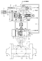
- FIG. 1 is a cross-sectional view showing an example of a fluid pressure drive valve 10 according to an embodiment of the present invention.
- the fluid pressure drive valve 10 opens and closes the main valve 11 by driving the main valve 11 arranged in the middle of the pipe 100 and the valve shaft 13 connected to the main valve 11 according to the fluid pressure of the driving fluid.
- the drive device 12 is provided, and the solenoid valve 1 having a function of controlling the supply and discharge of the drive fluid to the drive device 12 is provided.
- the fluid pressure drive valve 10 is installed in, for example, a pipe 100 through which various gases, oil, etc. flow in the plant equipment, and is an emergency shutoff for shutting off the flow of the pipe 100 in the event of an emergency stop such as when an abnormality occurs in the plant equipment. Used as a valve.
- the installation location and application of the fluid pressure drive valve 10 are not limited to the above examples.
- Air (air) A is supplied to the fluid pressure drive valve 10 from the air supply source 14 as an example of the drive fluid, and the air A from the air supply source 14 is passed through the first air pipe 140. Is supplied to the electromagnetic valve 1 and further supplied to the drive device 12 via the second air pipe 141. Further, the fluid pressure drive valve 10 includes a communication cable 150 for transmitting and receiving various data between the external device 15 and the solenoid valve 1, and a power cable 160 for supplying electric power from the external power supply 16 to the solenoid valve 1. And are connected.
- the driving fluid is not limited to the above-mentioned air A, and may be another gas or a liquid (for example, oil).
- the external device 15 is composed of, for example, a computer for plant management (including a local server and a cloud server), a diagnostic computer used by a maintenance inspector, or an external storage unit such as a USB memory or an external HDD. There is.
- the communication between the external device 15 and the solenoid valve 1 may be wireless communication.
- the fluid pressure drive valve 10 adopts an airless closing method. Therefore, during steady operation, the main valve 11 is fully opened by supplying air A (air supply) from the air supply source 14 to the drive device 12 via the solenoid valve 1, and during emergency stop or test operation. By discharging air A (exhaust) from the drive device 12 via the solenoid valve 1, the main valve 11 is fully closed.
- the fluid pressure drive valve 10 may adopt an airless open system. In that case, the fluid pressure drive valve 10 is fully opened by supplying the air A to the drive device 12, and the air A is discharged from the drive device 12.
- the main valve 11 may be fully closed.
- the main valve 11 is composed of, for example, a valve called a ball valve.
- the main valve 11 includes a valve box 110 arranged in the middle of the pipe 100 and a ball-shaped valve body 111 rotatably provided in the valve box 110, and is provided on the upper portion of the valve body 111. Is connected to the first end 130A of the valve shaft 13.
- the valve body 111 rotates in the valve box 110 in response to the valve shaft 13 being rotationally driven from 0 degrees to 90 degrees, and the main valve 11 can be switched between a fully open state (state shown in FIG. 1) and a fully closed state. ..
- the valve used as the main valve 11 is not limited to the ball valve, and may be another type such as a butterfly valve.
- the drive device 12 is arranged between the main valve 11 and the solenoid valve 1, for example, and is configured as a single-actuated air cylinder mechanism.
- the drive device 12 includes a cylindrical cylinder 120, a pair of pistons 122A and 122B provided in the cylinder so as to be reciprocally linearly movable, and connected via a piston rod 121, and a first piston 122A.
- a coil spring 123 provided on the side, an air supply / discharge port 124 formed on the second piston 122B side, a valve shaft 13 and a piston rod 121 arranged so as to penetrate the cylinder 120 along the radial direction. It is provided with a transmission mechanism 125 provided at a portion where the cylinders are orthogonal to each other.
- the drive device 12 is not limited to the single-acting type, and may be configured in another type such as a double-acting type.
- the first piston 122A is urged by the coil spring 123 in the direction of closing the main valve 11.
- the second piston 122B is pressed by the air A (air supply) supplied from the air supply / exhaust port 124 in the direction of opening the main valve 11 against the urging force of the coil spring 123.
- the transmission mechanism 125 is composed of, for example, a rack and pinion mechanism, a link mechanism, a cam mechanism, etc., and converts the reciprocating linear motion of the piston rod 121 into a rotary motion and transmits it to the valve shaft 13.
- the valve shaft 13 is formed in a shaft shape and is arranged so as to penetrate the drive device 12 in a rotatable state.
- the first end 130A of the valve shaft 13 is connected to the main valve 11, and the second end 130B of the valve shaft 13 is pivotally supported by the solenoid valve 1.
- the valve shaft 13 may have a plurality of shafts connected by, for example, a coupling or the like.
- the solenoid valve 1 has a function of controlling the supply and discharge of air A to the drive device 12, and is, for example, a three-way solenoid valve of a normally closed type (“open” when energized, “closed” when not energized) at two positions. It is configured as.
- the solenoid valve 1 has a spool portion 2 that switches the flow path through which the air A flows inside the accommodating portion 6 that functions as a housing of the indoor type or explosion-proof type solenoid valve 1, and is in an energized state (when energized or de-energized). It is provided with a solenoid unit 3 that displaces the spool unit 2 accordingly.
- the solenoid valve 1 is not limited to a two-position, normally closed type three-way solenoid valve, but may be a three-position solenoid valve, a normally open type, a four-way solenoid valve, or the like, and is composed of various formations based on any combination. May be. Further, in the present embodiment, the solenoid valve 1 is used as a pilot valve in the fluid pressure drive valve 10, but the application of the solenoid valve 1 is not limited to this.
- the spool portion 2 has an input port 20 connected to the air supply source 14 via the first air pipe 140, an output port 21 connected to the drive device 12 via the second air pipe 141, and a drive device. It is provided with an exhaust port 22 for discharging the exhaust from 12.
- the solenoid unit 3 displaces the spool unit 2 so as to communicate between the input port 20 and the output port 21 when energized, and communicates between the output port 21 and the exhaust port 22 when the power is off. , Displace the spool portion 2.
- the solenoid valve 1 when the solenoid valve 1 is energized, the air A (air supply) from the air supply source 14 is the first air pipe 140, the input port 20, the output port 21, and the second air pipe 141.
- the second piston 122B is pressed and the coil spring 123 is compressed by flowing in this order and being supplied to the air supply / discharge port 124.
- the valve shaft 13 is rotationally driven via the piston rod 121 and the transmission mechanism 125 by the amount that the piston rod 121 moves in response to the compression of the coil spring 123, the valve body 111 rotates in the valve box 110.
- the main valve 11 is operated in the fully open state.
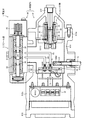
- FIG. 2 is a cross-sectional view showing an example of the solenoid valve 1 according to the embodiment of the present invention.
- the solenoid valve 1 includes a plurality of sensors 4 for acquiring the state of each portion of the solenoid valve 1 and a substrate 5 on which at least one of the plurality of sensors 4 is mounted.
- a spool portion 2, a solenoid portion 3, a plurality of sensors 4, and an accommodating portion 6 for accommodating the substrate 5 are provided.
- the accommodating portion 6 is adjacent to the first accommodating portion 60 accommodating the spool portion 2 and the first accommodating portion 60, and also accommodates the solenoid unit 3, the plurality of sensors 4, and the substrate 5.
- a terminal box 62 to which the communication cable 150 and the power cable 160 are connected is provided.
- the first accommodating portion 60 and the second accommodating portion 61 are made of, for example, a metal material such as aluminum.
- the first accommodating portion 60 has openings (not shown) that function as input ports 20, output ports 21, and exhaust ports 22, respectively.
- the second accommodating portion 61 includes a cylindrical housing 610 with both ends (first housing end 610a and second housing end 610b) open, a body 611 arranged inside the housing 610, and a second housing portion 61.
- a solenoid cover 612 that covers the solenoid portion 3 fixed to the housing end portion 610a of 1 from the outside air, and a terminal box cover 613 that covers the terminal box 62 fixed to the second housing end portion 610b from the outside air are provided.
- the housing 610 has a shaft insertion port 610c formed in the lower portion thereof and into which the second end 130B of the valve shaft 13 is inserted, a body insertion port 610d formed in the upper portion thereof into which the body 611 is inserted, and a second. It has a cable insertion port 610e formed on the housing end portion 610b side of the above and into which the communication cable 150 and the power cable 160 are inserted.
- the first accommodating portion 60 and the second accommodating portion 61 are branched from the input side flow path 26 so as to penetrate the body 611, and between the input side flow path 26 and the first pressure sensor 40.
- a spool flow path 65 through which air A for interlocking with the portion 3 flows is formed.
- the spool portion 2 includes a spool hole 23 formed in a second accommodating portion 61 that functions as a spool case, a spool valve 24 that is movably arranged in the spool hole 23, and a spool that urges the spool valve 24.
- the spring 25 the input side flow path 26 communicating between the input port 20 and the spool hole 23, the output side flow path 27 communicating between the output port 21 and the spool hole 23, the exhaust port 22 and the spool hole 23. It is provided with an exhaust flow path 28 that communicates between the two.
- the solenoid unit 3 is arranged in a solenoid case 30, a solenoid coil 31 housed in the solenoid case 30, a movable iron core 32 movably arranged in the solenoid coil 31, and a fixed state in the solenoid coil 31.
- a fixed iron core 33 and a solenoid spring 34 for urging the movable iron core 32 are provided.
- the solenoid coil 31 When the solenoid valve 1 is switched from the non-energized state to the energized state, the solenoid coil 31 generates an electromagnetic force when the coil current flows through the solenoid coil 31 in the solenoid unit 3, and the movable iron core is generated by the electromagnetic force.
- the flow state of the air A flowing through the spool flow path 65 is switched.
- the flow state of the air A flowing through the spool flow path 65 is switched, so that the spool valve 24 is moved against the urging force of the spool spring 25, so that the input port 20 and the exhaust are exhausted.
- the state of communicating with the port 22 can be switched to the state of communicating between the input port 20 and the output port 21.
- the substrate 5 includes a first substrate 50 arranged so that the substrate surfaces 500A and 500B are arranged along the valve shaft 13 inserted from the shaft insertion port 610c, and a second substrate 51 arranged close to the terminal box 62. And a third substrate 52 arranged close to the solenoid unit 3.
- the body 611, the solenoid unit 3, and the third substrate 52 are arranged on the first substrate surface 500A side.
- the second substrate 51 and the terminal box 62 are arranged on the second substrate surface 500B side opposite to the first substrate surface 500A side.
- the sensor 4 mounted on the first substrate 50 includes, for example, a first pressure sensor 40 for measuring the fluid pressure of air A flowing through the input side flow path 26 and the first flow path 63, and an output side flow path.
- the second pressure sensor 41 that measures the fluid pressure of the air A flowing through the 27 and the second flow path 64 and the rotation angle when the valve shaft 13 is rotationally driven are measured, and the main valve 11 is measured according to the rotation angle.
- the first pressure sensor 40, the second pressure sensor 41, and the main valve opening sensor 42 are integrated on one substrate (first substrate 50), so that the solenoid valve 1 and the fluid pressure drive valve 10 are integrated. It is possible to realize the monitoring function required for properly diagnosing whether or not the operation is normal with a simple configuration.
- the main valve opening sensor 42 is composed of, for example, a magnetic sensor, measures the magnetic strength generated by the permanent magnet 131 attached to the second end 130B of the valve shaft 13, and measures the magnetic strength. Correspondingly, the valve opening information of the main valve 11 is acquired.
- the main valve opening sensor 42 faces the outer periphery of the valve shaft 13 around the axis of the first board surface 500A of the first board 5 arranged along the valve shaft 13 inserted from the shaft insertion port 610c. It is placed in the position to be used. As a result, in the accommodating portion 6, the main valve opening sensor 42 mounted on the first substrate 50 and the second end portion 130B of the valve shaft 13 are brought close to each other without wasting the arrangement space. The valve opening information can be accurately acquired.
- the main valve opening sensor 42 is mounted on the first substrate 50 closer to the shaft insertion port 610c than the first pressure sensor 40 and the second pressure sensor 41.
- the first flow path 63 communicating with the first pressure sensor 40 and the second flow path 64 communicating with the second pressure sensor 40 are the second of the main valve opening sensor 42 and the valve shaft 13. Since it is arranged at a position separated from the end portion 130B of 2, the shape and arrangement of the first flow path 63 and the second flow path 64 can be simplified.
- FIG. 3 is a block diagram showing an example of the solenoid valve 1 according to the embodiment of the present invention.
- FIG. 4 is a schematic view showing an example of mounting a plurality of sensors 4 on the substrate 5 according to the embodiment of the present invention. Note that FIG. 4 does not strictly indicate the position where each sensor 4 is mounted on the substrate 5, and each sensor 4 is mounted on any of the first to third substrates 50 to 52. It shows the mounting state of the sensor.
- the solenoid valve 1 communicates with the control unit 7 that controls the solenoid valve 1 and the external device 15 in addition to the above-mentioned first to third substrates 50 to 52 and the plurality of sensors 4. It includes a communication unit (external transmission unit) 8 having a function and a power supply circuit unit 9 connected to the external power supply 16.
- the plurality of sensors 4 measure the supply voltage to the solenoid unit 3 in addition to the above-mentioned first pressure sensor 40, second pressure sensor 41, and main valve opening sensor 42 as a sensor group for measuring the physical quantity of each part.
- the plurality of sensors 4 measure at least one of the total energization time for the solenoid unit and the current energization continuous time as the operation time of the solenoid unit 3 as a sensor group for acquiring information on the operation history of each unit.
- a total of 47 and an operation counter 48 for counting the number of operations of each of the solenoid valve 1, the drive device 12, and the main valve 11 are provided.
- the control unit 7 processes information indicating the state of each part of the solenoid valve 1 acquired by the plurality of sensors 4, and also controls the state of energization of the microcontroller 70 that controls each part of the solenoid valve 1 and the solenoid unit 3.
- a valve test switch 71 that opens and closes the main valve 11 during a test operation is provided.
- the microcontroller 70 includes a processor (not shown) such as a CPU (Central Processing Unit) and an internal storage unit 701 composed of a ROM (Read Only Memory), a RAM (Random Access Memory), and the like.
- a processor such as a CPU (Central Processing Unit) and an internal storage unit 701 composed of a ROM (Read Only Memory), a RAM (Random Access Memory), and the like.
- the internal storage unit 701 stores a set value when the solenoid valve 1 operates, temporary storage data when the solenoid valve 1 operates, an electromagnetic valve control program that controls the operation of the solenoid valve 1, and the like. ..
- the processor of the microcontroller 70 is a monitoring processing unit 700 that executes a monitoring process for monitoring the state of each part of the solenoid valve 1 by a plurality of sensors 4 by executing a solenoid valve control program stored in the internal storage unit 701. Function.
- the monitoring processing unit 700 has at least one of the plurality of sensors 4 regardless of whether or not the main valve 11 is opened / closed (hereinafter, referred to as “first monitored sensor 4A”). Is used to execute the "first monitoring process” for monitoring the state of the solenoid valve 1. Further, the monitoring processing unit 700 uses at least one of the plurality of sensors 4 (hereinafter, referred to as “second monitoring target sensor 4B”) during the unsteady operation in which the main valve 11 is opened and closed. The "second monitoring process” for monitoring the state of the solenoid valve 1 is executed.
- the first monitored sensor 4A is, for example, all of the plurality of sensors 4 (first pressure sensor 40, second pressure sensor 41, main valve opening sensor 42, voltage sensor 43, current / resistance sensor 44).
- the second monitored sensor 4B is, for example, the second pressure sensor 41 and the main valve opening degree sensor 42, but is not limited to these examples.
- the monitoring processing unit 700 acquires the state of the solenoid valve 1 acquired by the first monitored sensor 4A in the first sampling period (for example, every 10 seconds) as the first acquired data. Then, each time the first acquired data is acquired, it is sequentially transmitted to the external device 15 via the communication unit 8.
- the monitoring processing unit 700 performs a second monitoring target in a second sampling cycle (for example, 10 msec interval) shorter than the first sampling cycle in the operation period in which the solenoid valve 1 is operated.
- the state of the solenoid valve 1 acquired by the sensor 4B is acquired as the second acquisition data, respectively.
- the monitoring processing unit 700 internally sets the acquired data group formed by associating the second acquired data acquired within the operation period with the acquired acquisition time of each of the second acquired data as temporary storage data. It is stored in the storage unit 701. Then, the acquired data group stored in the internal storage unit 701 is transmitted to the external device 15 at a predetermined timing.
- the valve test switch 71 receives a command from the microcontroller 70 when a predetermined test operation condition is satisfied, and as a test operation, a full stroke test (hereinafter, referred to as “FST”) or a partial stroke of the solenoid valve 1 is performed. A test (hereinafter referred to as "PST”) is executed.
- FST full stroke test
- PST partial stroke of the solenoid valve 1
- FST diagnoses an abnormality in the fluid pressure drive valve 10 by operating the main valve 11 from the fully open state to the fully closed state and returning it to the fully open state.
- the PST partially closes the main valve 11 from the fully open state to a predetermined opening state and returns it to the fully open state, so that the main valve 11 is not operated to the fully closed state (that is, without stopping the plant equipment). ,
- the abnormality of the fluid pressure drive valve 10 is diagnosed.
- the fluid pressure drive is performed by determining whether or not the operation is completed within a predetermined set time based on the state of the solenoid valve 1 acquired by each sensor 4 when the main valve 11 is operated. It is possible to diagnose the abnormality of the valve 10. Further, by analyzing the time-series change of the state of the solenoid valve 1 acquired by each sensor 4 when the main valve 11 is operated (for example, comparing with the time-series change at the normal time), the fluid pressure drive valve It is possible to diagnose 10 abnormalities.
- test operation conditions for example, the execution time or a specific designated date and time according to the execution frequency (for example, once a year) designated as the set value of the internal storage unit 701 may arrive, or the external device 15 (for example, once a year) may be used. , Plant management computer), or when the test execution button (not shown) provided on the solenoid valve 1 is operated by the administrator, the test operation condition is satisfied. Should be executed.
- the communication unit 8 is a communication modem 80 that transmits / receives data to / from the external device 15 in accordance with the HART (Highway Addressable Remote Transducer) communication standard, and a loop current controller that inputs / outputs a control current (analog signal of 4 to 20 mA). It includes 81.
- the communication modem 80 converts the data to be transmitted into a frequency signal
- the loop current controller 81 transmits a superimposed signal obtained by superimposing the frequency signal on the control current to the external device 15.
- the communication modem 80 converts the frequency signal into data to be received.
- the power supply circuit unit 9 is supplied from the external power supply 16 via the power cable 160 and the reverse voltage protection circuit 90 that protects the control unit 7 from the reverse voltage generated when the power cable 160 is reversely connected to the terminal box 62. It is provided with an internal power supply circuit 91 that converts the generated power into predetermined voltages and currents and supplies them to each part of the electromagnetic valve 1 (solar part 3, sensor 4, substrate 5, control part 7, communication part 8, etc.).
- the first substrate 50 includes a first pressure sensor 40, a second pressure sensor 41, a main valve opening sensor 42, a voltage sensor 43, a current / resistance sensor 44, a temperature sensor 45, and an operation.
- a time meter 47, an operation counter 48, a control unit 7, a communication modem 80, and a reverse voltage protection circuit 90 are mounted.
- the loop current controller 81 and the internal power supply circuit 91 are mounted on the second substrate 51.
- the magnetic sensor 46 is mounted on the third substrate 52.
- the plurality of sensors 4 are not limited to the above sensors 40 to 48, and may further include sensors for acquiring information on other physical quantities and operation histories, and some of these sensors 40 to 48 may be provided. It may be omitted. Further, the mounting state of the sensors 40 to 48 when the plurality of sensors 4 are mounted on the substrates 50 to 52 is not limited to the example shown in FIG. 4, and may be appropriately changed. Further, the number of substrates 5 accommodated in the accommodating portion 6 and the arrangement of the substrates 50 to 52 with respect to the accommodating portion 6 may be appropriately changed.
- the sensors 40 to 48 are not limited to those in which each sensor is individually provided as shown in FIGS. 3 and 4, and the specific sensor also functions as another sensor. Sensors may not be provided individually.
- the magnetic sensor 46 measures the magnetic strength generated by the solenoid unit 3, and the current / resistance sensor 44 obtains the current value when the solenoid unit 3 is energized based on the magnetic strength. It does not have to be provided individually.
- the microcontroller 70 may have a built-in sensor function or a part of the sensor function.
- the microcontroller 70 has a built-in operating time meter 47 and an operation counter 48. , The operation time meter 47 and the operation counter 48 may not be provided separately.
- the drive device 12 has been described as rotating the valve shaft 13, but the valve shaft 13 may be driven in a reciprocating linear manner.
- the main valve 11 whose opening / closing operation is performed in response to the reciprocating linear drive of the valve shaft 13, for example, a type such as a gate valve or a globe valve may be used.
- the accommodating portion 6 has a shaft insertion port into which the end portion of the valve shaft driven linearly by the drive device 12 is inserted, and the valve shaft is driven linearly reciprocatingly. It accommodates a driving force transmission mechanism (for example, a rack and pinion mechanism, a link mechanism, a cam mechanism, etc.) that rotationally drives the rotating shaft in conjunction with the movement.
- the substrate surface of the first substrate 50 is arranged along the rotation axis, and the main valve opening sensor 42 is located on the outer periphery of the substrate surface of the first substrate 50 around the axis of the rotation axis. It may be placed at opposite positions and the rotation angle of the rotation shaft may be measured in order to obtain the valve opening degree of the main valve 11.
- the above-mentioned driving force transmission mechanism may be arranged outside the accommodating portion 6, and in this case, the end portion of the rotary shaft rotationally driven by the driving force transmission mechanism is inserted from the shaft insertion port.
- the substrate surface of the first substrate 50 is arranged along the rotation axis inserted from the shaft insertion port, and the main valve opening sensor 42 determines the valve opening of the main valve 11 so that the valve shaft Instead of the rotation angle of 13, the rotation angle of the rotation axis may be measured.
- the solenoid valve 1 As described above, according to the solenoid valve 1 according to the above embodiment, at least one of the spool unit 2, the solenoid unit 3, the plurality of sensors 4, and the plurality of sensors 4 is mounted on the accommodating unit 6.
- the substrate 5 having the control unit 7 is housed together with the control unit 7.
- the spool portion 2 and the solenoid portion 3 are accommodated in the accommodating portion 6, and in the accommodating portion 6, a plurality of sensors 4 acquire the state of each portion of the solenoid valve 1 and among them. At least one is mounted on the substrate 5 having the control unit 7.
- the monitoring function for monitoring the state of each part is integrated in the accommodating part 6, so that the state of each part of the solenoid valve 1 can be monitored by the solenoid valve 1 alone.
- the device configuration can be simplified.
- a spool portion 2 mainly constituting a drive fluid system circuit
- a solenoid unit 3 mainly constituting an electric system circuit
- a plurality of sensors 4 and a substrate are provided. Since the 5 and the 5 are housed separately, the air system circuit and the electrical system circuit can be efficiently arranged.
- the solenoid portion 3 constituting the solenoid valve 1 of the electrical circuit is arranged on the first substrate surface 500A side with the first substrate 50 as a boundary, and the second substrate is provided. Since the second board 51 and the terminal box 62 constituting the communication unit 8 and the power supply circuit unit 9 of the electrical circuits are arranged on the surface 500B side, the electrical circuits can be arranged more efficiently. ..
- Spool flow path 70 ... Microcontroller, 71 ... Valve test switch, 80 ... communication modem, 81 ... loop current controller, 90 ... Reverse voltage protection circuit, 91 ... Internal power supply circuit, 100 ... Piping, 110 ... Valve box, 111 ... Valve body, 120 ... Cylinder, 121 ... Piston rod, 122A ... 1st piston, 122B ... 2nd piston, 123 ... Coil spring, 124 ... Air supply / exhaust port, 125 ... Transmission mechanism, 130A ... 1st end, 130B ... 2nd end, 140 ... 1st air pipe, 141 ... 2nd air pipe, 150 ... communication cable, 160 ... power cable, 500A ...
Landscapes
- Engineering & Computer Science (AREA)
- General Engineering & Computer Science (AREA)
- Mechanical Engineering (AREA)
- Indication Of The Valve Opening Or Closing Status (AREA)
- Magnetically Actuated Valves (AREA)
- Fluid-Driven Valves (AREA)
Priority Applications (2)
| Application Number | Priority Date | Filing Date | Title |
|---|---|---|---|
| CN202180006785.1A CN114787547B (zh) | 2020-03-09 | 2021-02-25 | 电磁阀 |
| KR1020227003340A KR102590655B1 (ko) | 2020-03-09 | 2021-02-25 | 전자 밸브 |
Applications Claiming Priority (2)
| Application Number | Priority Date | Filing Date | Title |
|---|---|---|---|
| JP2020040356A JP6783484B1 (ja) | 2020-03-09 | 2020-03-09 | 電磁弁 |
| JP2020-040356 | 2020-03-09 |
Publications (1)
| Publication Number | Publication Date |
|---|---|
| WO2021182115A1 true WO2021182115A1 (ja) | 2021-09-16 |
Family
ID=73043475
Family Applications (1)
| Application Number | Title | Priority Date | Filing Date |
|---|---|---|---|
| PCT/JP2021/007034 Ceased WO2021182115A1 (ja) | 2020-03-09 | 2021-02-25 | 電磁弁 |
Country Status (4)
| Country | Link |
|---|---|
| JP (2) | JP6783484B1 (https=) |
| KR (1) | KR102590655B1 (https=) |
| CN (1) | CN114787547B (https=) |
| WO (1) | WO2021182115A1 (https=) |
Families Citing this family (3)
| Publication number | Priority date | Publication date | Assignee | Title |
|---|---|---|---|---|
| JP7805885B2 (ja) * | 2022-07-12 | 2026-01-26 | Ckd株式会社 | 比例弁制御装置、及び比例弁制御方法 |
| KR102882345B1 (ko) * | 2025-04-04 | 2025-11-06 | 국방과학연구소 | 전기활성물질 기반 가변 유로 제어를 이용한 j-t 냉각 시스템 및 방법 |
| CN120576254A (zh) * | 2025-08-05 | 2025-09-02 | 浙江贝尔控制阀门有限公司 | 带远程及就地pst功能的控制阀 |
Citations (3)
| Publication number | Priority date | Publication date | Assignee | Title |
|---|---|---|---|---|
| JP2018076901A (ja) * | 2016-11-08 | 2018-05-17 | Ckd株式会社 | 電磁弁 |
| WO2018167964A1 (ja) * | 2017-03-17 | 2018-09-20 | 金子産業株式会社 | 遮断弁制御装置、遮断弁制御システム、遮断弁制御係数算出方法及び遮断弁制御方法 |
| JP2020060202A (ja) * | 2018-10-05 | 2020-04-16 | Ckd株式会社 | 電磁弁 |
Family Cites Families (21)
| Publication number | Priority date | Publication date | Assignee | Title |
|---|---|---|---|---|
| JP3062979B2 (ja) * | 1992-09-17 | 2000-07-12 | 株式会社オゼ | 電磁弁 |
| WO2002041333A1 (en) * | 1999-05-14 | 2002-05-23 | Yuken Kogyo Kabushiki Kaisha | Electromagnetic operating device |
| JP4390231B2 (ja) * | 1999-05-14 | 2009-12-24 | 油研工業株式会社 | 電磁操作装置 |
| JP3590762B2 (ja) * | 2000-09-05 | 2004-11-17 | Smc株式会社 | 位置検出機能を備えたマニホールドバルブ |
| JP4288643B2 (ja) * | 2002-02-20 | 2009-07-01 | 株式会社Inax | 定量止水弁装置 |
| JP4063223B2 (ja) * | 2003-05-16 | 2008-03-19 | トヨタ自動車株式会社 | 電磁駆動式ダイカスト減圧バルブおよびその駆動方法、ダイカスト装置 |
| JP4369292B2 (ja) * | 2004-05-06 | 2009-11-18 | タイコ フローコントロールジャパン株式会社 | 緊急遮断弁装置 |
| JP5053027B2 (ja) * | 2007-10-12 | 2012-10-17 | タイコ・フロー・サーヴィシーズ・アー・ゲー | 緊急遮断弁装置 |
| KR100916671B1 (ko) * | 2007-11-30 | 2009-09-08 | 백백순 | 타이머가 구비된 밸브 |
| JP5093090B2 (ja) * | 2008-12-25 | 2012-12-05 | アイシン・エィ・ダブリュ株式会社 | 電磁弁装置および動力伝達装置 |
| DE202009012183U1 (de) | 2009-09-08 | 2009-11-26 | Bürkert Werke GmbH & Co. KG | Manuell betätigbares Ansteuermodul |
| KR101166300B1 (ko) * | 2010-05-13 | 2012-07-18 | 영남대학교 산학협력단 | 공압작동기 |
| CN102313065B (zh) * | 2011-07-21 | 2013-07-17 | 同济大学 | 一种基于电磁阀阵的气动比例调节装置 |
| DE102014010815A1 (de) * | 2014-07-23 | 2016-01-28 | Wabco Gmbh | Elektropneumatisches Regelventil |
| CN107249908B (zh) * | 2014-12-16 | 2020-02-07 | Aktv8有限公司 | 电子控制的车辆悬架系统和制造方法 |
| DE102015206401A1 (de) * | 2015-04-10 | 2016-10-13 | Robert Bosch Gmbh | Linearer Wegaufnehmer für einen Ventilschieber eines, insbesondere stetig verstellbaren, Hydraulikventils und Hydraulikventil mit dem linearen Wegaufnehmer |
| JP6278317B2 (ja) * | 2015-05-08 | 2018-02-14 | Smc株式会社 | 流路切換ユニット |
| JP6521807B2 (ja) * | 2015-09-08 | 2019-05-29 | 日立オートモティブシステムズ株式会社 | 電磁弁、液圧制御装置およびブレーキ装置 |
| JP6825405B2 (ja) * | 2017-02-15 | 2021-02-03 | 日本電産トーソク株式会社 | バルブ装置 |
| KR101830165B1 (ko) | 2017-04-11 | 2018-02-21 | 한국본산 주식회사 | 밸브용 액추에이터 |
| JP2019211180A (ja) * | 2018-06-07 | 2019-12-12 | 株式会社デンソー | 弁装置 |
-
2020
- 2020-03-09 JP JP2020040356A patent/JP6783484B1/ja active Active
- 2020-09-30 JP JP2020164563A patent/JP7440006B2/ja active Active
-
2021
- 2021-02-25 WO PCT/JP2021/007034 patent/WO2021182115A1/ja not_active Ceased
- 2021-02-25 KR KR1020227003340A patent/KR102590655B1/ko active Active
- 2021-02-25 CN CN202180006785.1A patent/CN114787547B/zh active Active
Patent Citations (3)
| Publication number | Priority date | Publication date | Assignee | Title |
|---|---|---|---|---|
| JP2018076901A (ja) * | 2016-11-08 | 2018-05-17 | Ckd株式会社 | 電磁弁 |
| WO2018167964A1 (ja) * | 2017-03-17 | 2018-09-20 | 金子産業株式会社 | 遮断弁制御装置、遮断弁制御システム、遮断弁制御係数算出方法及び遮断弁制御方法 |
| JP2020060202A (ja) * | 2018-10-05 | 2020-04-16 | Ckd株式会社 | 電磁弁 |
Also Published As
| Publication number | Publication date |
|---|---|
| KR102590655B1 (ko) | 2023-10-17 |
| JP2021139487A (ja) | 2021-09-16 |
| CN114787547B (zh) | 2024-04-23 |
| JP7440006B2 (ja) | 2024-02-28 |
| CN114787547A (zh) | 2022-07-22 |
| JP6783484B1 (ja) | 2020-11-11 |
| KR20220028062A (ko) | 2022-03-08 |
| JP2021139494A (ja) | 2021-09-16 |
Similar Documents
| Publication | Publication Date | Title |
|---|---|---|
| JP6783484B1 (ja) | 電磁弁 | |
| JP6783490B1 (ja) | 駆動装置及び流体圧駆動弁 | |
| KR102629090B1 (ko) | 기계 학습 장치, 데이터 처리 시스템, 추론 장치 및 기계 학습 방법 | |
| JP6795231B1 (ja) | 電磁弁 | |
| KR20240032108A (ko) | 데이터 처리 시스템 및 데이터 처리 방법 | |
| WO2021192983A1 (ja) | 機械学習装置、データ処理システム、推論装置及び機械学習方法 | |
| WO2021220766A1 (ja) | 機械学習装置、データ処理システム、推論装置及び機械学習方法 | |
| JP6795233B1 (ja) | 電磁弁 | |
| JP6783489B1 (ja) | 機械学習装置、データ処理システム、推論装置及び機械学習方法 | |
| WO2023053608A1 (ja) | データベース生成装置、状態判定装置、データベース生成方法及び状態判定方法 | |
| JP6779459B1 (ja) | 機械学習装置、データ処理システム、推論装置及び機械学習方法 | |
| JP7058447B1 (ja) | 機械学習装置、データ処理システム、推論装置及び機械学習方法 | |
| JP6783487B1 (ja) | 機械学習装置、データ処理システム、推論装置及び機械学習方法 | |
| JP6779457B1 (ja) | 機械学習装置、データ処理システム、推論装置及び機械学習方法 | |
| JP7536290B2 (ja) | 性状判定装置、データベース生成装置、性状判定方法及びデータベース生成方法 | |
| JP6779456B1 (ja) | 機械学習装置、データ処理システム、推論装置及び機械学習方法 | |
| JP2022092744A (ja) | 組立条件提示装置、及び、組立条件提示方法 |
Legal Events
| Date | Code | Title | Description |
|---|---|---|---|
| 121 | Ep: the epo has been informed by wipo that ep was designated in this application |
Ref document number: 21766845 Country of ref document: EP Kind code of ref document: A1 |
|
| ENP | Entry into the national phase |
Ref document number: 20227003340 Country of ref document: KR Kind code of ref document: A |
|
| NENP | Non-entry into the national phase |
Ref country code: DE |
|
| 122 | Ep: pct application non-entry in european phase |
Ref document number: 21766845 Country of ref document: EP Kind code of ref document: A1 |