WO2021182064A1 - 薬液の精製方法、薬液の製造方法、薬液 - Google Patents
薬液の精製方法、薬液の製造方法、薬液 Download PDFInfo
- Publication number
- WO2021182064A1 WO2021182064A1 PCT/JP2021/006184 JP2021006184W WO2021182064A1 WO 2021182064 A1 WO2021182064 A1 WO 2021182064A1 JP 2021006184 W JP2021006184 W JP 2021006184W WO 2021182064 A1 WO2021182064 A1 WO 2021182064A1
- Authority
- WO
- WIPO (PCT)
- Prior art keywords
- chemical solution
- filter
- purifying
- liquid
- purified
- Prior art date
- Legal status (The legal status is an assumption and is not a legal conclusion. Google has not performed a legal analysis and makes no representation as to the accuracy of the status listed.)
- Ceased
Links
Images



Classifications
-
- B—PERFORMING OPERATIONS; TRANSPORTING
- B01—PHYSICAL OR CHEMICAL PROCESSES OR APPARATUS IN GENERAL
- B01D—SEPARATION
- B01D71/00—Semi-permeable membranes for separation processes or apparatus characterised by the material; Manufacturing processes specially adapted therefor
- B01D71/06—Organic material
- B01D71/26—Polyalkenes
- B01D71/262—Polypropylene
-
- B—PERFORMING OPERATIONS; TRANSPORTING
- B01—PHYSICAL OR CHEMICAL PROCESSES OR APPARATUS IN GENERAL
- B01D—SEPARATION
- B01D61/00—Processes of separation using semi-permeable membranes, e.g. dialysis, osmosis or ultrafiltration; Apparatus, accessories or auxiliary operations specially adapted therefor
- B01D61/14—Ultrafiltration; Microfiltration
-
- B—PERFORMING OPERATIONS; TRANSPORTING
- B01—PHYSICAL OR CHEMICAL PROCESSES OR APPARATUS IN GENERAL
- B01D—SEPARATION
- B01D61/00—Processes of separation using semi-permeable membranes, e.g. dialysis, osmosis or ultrafiltration; Apparatus, accessories or auxiliary operations specially adapted therefor
- B01D61/14—Ultrafiltration; Microfiltration
- B01D61/22—Controlling or regulating
-
- B—PERFORMING OPERATIONS; TRANSPORTING
- B01—PHYSICAL OR CHEMICAL PROCESSES OR APPARATUS IN GENERAL
- B01D—SEPARATION
- B01D71/00—Semi-permeable membranes for separation processes or apparatus characterised by the material; Manufacturing processes specially adapted therefor
- B01D71/06—Organic material
- B01D71/26—Polyalkenes
- B01D71/261—Polyethylene
-
- B—PERFORMING OPERATIONS; TRANSPORTING
- B01—PHYSICAL OR CHEMICAL PROCESSES OR APPARATUS IN GENERAL
- B01D—SEPARATION
- B01D71/00—Semi-permeable membranes for separation processes or apparatus characterised by the material; Manufacturing processes specially adapted therefor
- B01D71/06—Organic material
- B01D71/30—Polyalkenyl halides
- B01D71/32—Polyalkenyl halides containing fluorine atoms
-
- B—PERFORMING OPERATIONS; TRANSPORTING
- B01—PHYSICAL OR CHEMICAL PROCESSES OR APPARATUS IN GENERAL
- B01D—SEPARATION
- B01D71/00—Semi-permeable membranes for separation processes or apparatus characterised by the material; Manufacturing processes specially adapted therefor
- B01D71/06—Organic material
- B01D71/56—Polyamides, e.g. polyester-amides
-
- H—ELECTRICITY
- H10—SEMICONDUCTOR DEVICES; ELECTRIC SOLID-STATE DEVICES NOT OTHERWISE PROVIDED FOR
- H10P—GENERIC PROCESSES OR APPARATUS FOR THE MANUFACTURE OR TREATMENT OF DEVICES COVERED BY CLASS H10
- H10P52/00—Grinding, lapping or polishing of wafers, substrates or parts of devices
Definitions
- the present invention relates to a method for purifying a chemical solution, a method for producing a chemical solution, and a chemical solution.
- Patent Document 1 is a method for purifying a chemical solution, which comprises a purification step of filtering a solution to be purified containing an organic solvent using a filter, wherein the filter is a contact between a test solution made of an organic solvent and a filter.
- An invention relating to a method for purifying a drug solution using a filter in which the content of a specific metal particle in a test solution after a test meets a specific requirement is described.
- a method for purifying a chemical solution containing an organic solvent using a purification device including a conduit and a filter arranged in the conduit, wherein gas is supplied to the conduit to purify the chemical solution. It has a ventilation step of passing the gas through the filter and a purification step of filtering the chemical solution using the filter through which the gas has passed, and the Fe component, Cr component, Ni component and Al component in the chemical solution.
- [2] The method for purifying a chemical solution according to [1], wherein the contents of each of the Fe component, the Cr component, the Ni component, and the Al component are 50 mass ppt or less with respect to the total mass of the chemical solution.
- [3] The method for purifying a chemical solution according to [1], wherein the contents of each of the Fe component, the Cr component, the Ni component, and the Al component are 10 mass ppt or less with respect to the total mass of the chemical solution.
- [4] The method for purifying a chemical solution according to any one of [1] to [3], wherein the gas is a gas of a non-polar organic compound.
- the purification apparatus further includes a container for storing the chemical solution to be delivered to the filter, and in the purification step, the pumping gas is introduced into the container to deliver the chemical solution, and the chemical solution is used as described above.
- the pumping gas is a gas of a non-polar organic compound.
- the organic solvents are propylene glycol monomethyl ether, propylene glycol monoethyl ether, propylene glycol monopropyl ether, propylene glycol monomethyl ether acetate, ethyl lactate, methyl methoxypropionate, ethyl propionate, cyclopentanone, cyclohexanone, ⁇ -butyrolactone, Diisoamyl ether, butyl acetate, isoamyl acetate, isopropanol, 4-methyl-2-pentanol, 1-hexanol, dimethylsulfoxide, n-methyl-2-pyrrolidone, diethylene glycol, ethylene glycol, dipropylene glycol, propylene glycol, ethylene carbonate
- the drug solution according to any one of [1] to [13], which is at least one selected from the group consisting of propylene carbonate, sulfolane, cycloheptanone, 2-heptanone,
- the present invention it is possible to provide a method for purifying a chemical solution, which has excellent removal performance of organic impurity particles in the chemical solution. Further, according to the present invention, it is possible to provide a method for producing a chemical solution and a chemical solution.
- the numerical range represented by using “-” means a range including the numerical values before and after "-" as the lower limit value and the upper limit value.
- the term “preparation” as used herein means not only synthesizing or blending a specific material to prepare the material, but also procuring a predetermined material by purchase.
- ppm means “parts-per-million ( 10-6 )
- ppb means “parts-per-billion ( 10-9 )”
- ppt means "parts-per-billion ( 10-9 )
- light means active light rays or radiation.
- exposure includes not only exposure with far ultraviolet rays, X-rays or EUV, but also drawing with particle beams such as electron beams and ion beams.
- a chemical solution containing an organic solvent is prepared by using a purification apparatus including a conduit and a filter arranged in the conduit. It is a method for purifying a chemical solution.
- This purification method includes a ventilation step of supplying gas to a pipeline and passing the gas through a filter, and a purification step of filtering a chemical solution using a filter through which the gas has passed.
- this purification method is a method for purifying a chemical solution in which the contents of each of the Fe component, Cr component, Ni component and Al component (hereinafter, also referred to as “specific metal component”) are specified.
- the present inventors have made the filter by passing the filter through a gas in the aeration step. After removing the residual water, the filter is easily charged by passing a chemical solution in which the content of each of the specific metal components is reduced to a specific range through the filter, and as a result, the present purification method is applied to the chemical solution. It is presumed that the performance of the filter that captures the contained organic impurity particles has improved, and the removal performance of the organic impurity particles in the chemical solution has improved.
- the "organic impurity particles" contained in the chemical solution are particles containing an organic compound, and have a diameter of 19 nm, which is measured by a method for measuring the content of organic impurity particles in the chemical solution described later. It means the above particles.
- the method for purifying a drug solution of the present invention is a method for purifying a drug solution using a purification device including a pipeline and a filter.
- a purification device including a pipeline and a filter.
- FIG. 1 is a schematic view showing an example of a purification apparatus used in this purification method.
- the purification device 10 includes a storage container 11, a filling device 13, a conduit 14 connecting the storage container 11 and the filling device 13, and a filter unit 12 arranged on the conduit 14.
- F 1 and F 2 indicate the transfer direction of the liquid (the liquid to be purified) in the purification apparatus 10.
- the storage container 11 is a container having a function of storing the liquid to be purified.
- To be purified liquid stored in the reservoir 11, as indicated by an arrow F 1, is sent to the filter unit 12 via line 14.
- the transfer of the liquid to be purified is carried out, for example, by operating a pump (not shown) arranged in the pipeline 14.
- the filter unit 12 contains a filter cartridge having a filter.
- the filter unit 12 has a function of filtering the liquid to be purified supplied through the conduit using a filter.
- Liquid purified by the filter, as indicated by the arrow F 2 the filter unit 12 via line 14 is fed to the filling device 13, is stored in the filling apparatus 13.
- the term "pipeline” is used in the present specification, unless otherwise specified, it means all sites where a chemical solution can exist inside between the storage container 11 and the filling device 13.
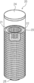
- FIG. 2 is a perspective view showing an example of a filter cartridge included in the filter unit 12.
- the filter cartridge 20 includes a cylindrical filter 21, a cylindrical core 22 that contacts the inner peripheral surface of the filter 21 and supports the filter 21, and a cylindrical sleeve that contacts the outer peripheral surface of the filter 21 and supports the filter 21. 23 and.
- the core 22 and the sleeve 23 are formed in a mesh shape so that a liquid can easily pass through.
- a cap 24 is arranged on the upper ends of the filter 21, the core 22, and the sleeve 23 to cover them. Further, at the lower end of the filter cartridge 20, an outlet 25 for letting the liquid flow out from the inside of the core 22 is arranged.
- FIG. 3 is a perspective view showing an example of the filter unit 12.
- FIG. 4 is a cross-sectional view showing an example of the filter unit 12.
- the filter unit 12 has a housing including a main body 31 and a lid 32, and a filter cartridge 20 housed in the housing.
- the lid 32 is provided with an inflow port 33 for connecting to the conduit 14 (a) and an outflow port 34 for connecting to the conduit 14 (b). Further, the lid 32 is provided with a first internal pipeline 35 connected to the inflow port 33 and a second internal pipeline 36 connected to the outlet 34.
- F 1 and F 2 indicate the transfer direction of the liquid (the liquid to be purified) in the filter unit 12.
- the liquid flows in from the inflow port 33 provided in the lid 32, flows into the inside of the main body 31 through the first internal pipeline 35 (F 1 in FIG. 4).
- the liquid that has flowed into the main body 31 passes through the filter cartridge 20. More specifically, the liquid flows in from the outer peripheral surface side of the sleeve 23, passes through the sleeve 23, the filter 21, and the core 22, and flows out from the inner peripheral surface of the core 22.
- the liquid flowing into the filter unit 12 is filtered and purified in the process of passing through the filter cartridge 20.
- the purified liquid that has flowed out near the central axis of the filter cartridge 20 is taken out of the filter cartridge 20 from the outlet 34 via the second internal conduit 36 (F 2 in FIG. 4).
- the purification device 10 includes a gas pipe (not shown) connected to the pipeline 14 (a) on the upstream side of the filter unit 12.
- gas can be supplied to the inside through a gas pipe.
- a regulating valve (not shown) for adjusting the flow rate of liquid and gas is located upstream of the branch portion where the pipeline 14 (a) and the gas pipe are connected. ) are provided respectively.
- the purification device 10 includes an exhaust pipe (not shown) connected to the pipeline 14 (b) on the downstream side of the filter unit 12. In the purification apparatus 10, gas can be discharged from the inside through the exhaust pipe.
- Each of the pipeline 14 (b) and the exhaust pipe has a regulating valve (not shown) for adjusting the flow rate of liquid and gas on the downstream side of the branch portion where the pipeline 14 (b) and the exhaust pipe are connected.
- a regulating valve (not shown) for adjusting the flow rate of liquid and gas on the downstream side of the branch portion where the pipeline 14 (b) and the exhaust pipe are connected.
- Each is provided.
- the purification apparatus 10 can perform a ventilation step (described later) for passing gas through the filter.
- the purification apparatus used in this purification method is not limited to the purification apparatus 10 having the configuration described above.
- the purification apparatus used in the present purification method may have a configuration other than the configuration described above.
- a pressure adjusting member such as a damper for adjusting the supply pressure of the liquid to the filter may be arranged on the pipe on the upstream side of the filter.
- the purification device 10 shown in FIG. 1 includes only one filter unit 12, the purification device may include a plurality of filters.
- the plurality of filters included in the purification apparatus may be arranged in series or in parallel with respect to the flow direction of the liquid.
- the purification device 10 shown in FIG. 1 has a configuration in which the purified liquid flowing out of the filter unit 12 is transferred to the filling device 13, but the purification device transfers the liquid flowing out of the filter unit 12 to the storage container 11. It may have a configuration in which it is returned and passed through the filter unit 12 again.
- a filtration method is called circulation filtration. From the viewpoint of productivity and from the viewpoint of suppressing the inclusion of impurities and other traps trapped in the filter in the liquid again, a purification method in which the liquid to be purified is passed through the filter only once without performing circulation filtration. Is preferable.
- the filter cartridge 20 shown in FIG. 2 has a filter 21, a core 22 and a sleeve 23, but the filter cartridge may have a configuration in which one or both of the core and the sleeve are not provided. .. That is, the filter cartridge may be formed only of the filter.
- the filter cartridge may have a flat or pleated filter. By using the pleated filter, the filtration area through which the liquid passes becomes wider, so that the flow rate of the liquid can be increased and the productivity can be improved.
- the purification device 10 includes the filter 21 housed in the filter cartridge 20, a filter not housed in the filter cartridge may be used.
- the purification apparatus may have, for example, a mode in which a liquid is passed through a filter formed in a flat plate shape.
- the inflow port 33 and the outflow port 34 are provided in the lid 32, but a filter unit in which the inflow port and the outflow port are provided in a member other than the lid may be used.
- the filter unit 12 shown in FIGS. 3 and 4 has a main body 31 and a lid 32, a filter unit in which the main body and the lid are integrally formed may be used.
- a gas pipe having a function of supplying gas is connected to the pipe line 14 (a), but the position where the gas pipe is connected is not particularly limited. It may be connected to an internal pipeline (upstream side or downstream side of the filter) in the filter unit and / or a pipeline on the downstream side of the filter unit. Further, in the above-mentioned purification apparatus 10, an exhaust pipe having a function of discharging gas is connected to the pipe line 14 (b), but the position where the exhaust pipe is connected is not particularly limited. For example, in the filter unit. It may be connected to an internal pipeline (upstream or downstream of the filter) and / or a pipeline upstream of the filter unit. Further, the purification device may not be provided with an exhaust pipe, and the gas may be discharged from the filling device or the downstream side of the filling device.
- the pore size of the filter is not particularly limited as long as it is used for filtering the liquid to be purified.
- the pore diameter of the filter is preferably 20 nm or less, more preferably 5 nm or less, still more preferably 2 nm or less, because the effect of the present invention is more excellent.
- the lower limit is not particularly limited, but is preferably 1 nm or more.
- the pore size of the filter is defined by the bubble point of isopropanol (IPA) or HFE-7200 (“Novec 7200”, manufactured by 3M, Hydrofluoroether, C 4 F 9 OC 2 H 5). It means the determined hole diameter.
- the material constituting the filter is not particularly limited, and for example, polyethylene (PE), polyolefin (including high density and ultrahigh molecular weight) such as polypropylene (PP); nylon (including nylon 6 and nylon 66). ) And the like; polyimide; polyamideimide; polyester such as polyethylene terephthalate; polyether sulfone; cellulose; polytetrafluoroethylene (PTFE), and a fluororesin such as perfluoroalkoxyalkane; and the above polymer (or resin). Derivatives of.
- PE polyethylene
- polyolefin including high density and ultrahigh molecular weight
- PP polypropylene
- nylon including nylon 6 and nylon 66
- polyimide polyamideimide
- polyester such as polyethylene terephthalate
- polyether sulfone cellulose
- PTFE polytetrafluoroethylene
- fluororesin such as perfluoroalkoxyalkane
- a material consisting of at least one selected from the group consisting of polyolefin, polyamide, polyimide, polyamideimide, polyester, polyethylene, cellulose, fluororesin, and derivatives thereof is preferable, and the effect of the present invention is more excellent. Therefore, polyethylene, polypropylene, nylon or fluororesin is more preferable, and PTFE is even more preferable.
- the material constituting the filter include diatomaceous earth and glass.
- the material constituting the filter may be a derivative of the above polymer.
- the derivative include those in which an ion exchange group is introduced into the polymer by a chemical modification treatment.
- the ion exchange group include a cation exchange group such as a sulfonic acid group, a carboxy group and a phosphoric acid group, and an anion exchange group such as a secondary, tertiary and quaternary ammonium group.
- the method for introducing the ion exchange group into the polymer is not particularly limited, and examples thereof include a method in which a compound having an ion exchange group and a polymerizable group is reacted with the polymer to graft the polymer.
- polyolefin polyethylene, polypropylene, etc.
- ionizing radiation ⁇ -ray, ⁇ -ray, ⁇ -ray, X-ray, electron beam, etc.
- an active moiety radical
- the irradiated polyolefin is immersed in a monomer-containing solution to graft-polymerize the monomer.
- a product in which this monomer is bonded to polyolefin as a graft polymerization side chain is produced.
- a polyolefin fiber having this monomer as a side chain is brought into contact with a compound having an anion exchange group or a cation exchange group, and the two are reacted to introduce an ion exchange group into the graft-polymerized side chain monomer.
- a compound having an anion exchange group or a cation exchange group You get things.
- an ion exchange group is not introduced into the polyolefin fiber which is the main chain, and an ion exchange group is introduced into the monomer of the side chain graft-polymerized on the main chain.
- the filter may have a configuration in which a woven fabric or non-woven fabric having an ion exchange group formed by a radiation graft polymerization method is combined with a conventional glass wool, woven fabric, or non-woven fabric.
- the filter may have a surface treatment other than chemical modification.
- the surface treatment method is not particularly limited, and a known method can be used. Examples of the surface treatment method include plasma treatment, hydrophobic treatment, coating, gas treatment, and sintering.
- Plasma treatment is preferable because the surface of the filter becomes hydrophilic.
- the water contact angle on the surface of the filter hydrophilized by plasma treatment is not particularly limited, but the static contact angle at 25 ° C. measured by a contact angle meter is preferably 60 ° or less, preferably 50 ° or less. More preferably, it is more preferably 30 ° or less.
- the pore structure of the filter is not particularly limited, and may be appropriately selected depending on the form of impurities contained in the liquid to be purified.
- the pore structure of the filter means a structure such as a pore size distribution, a positional distribution of pores in the filter, and a shape of pores, which differs depending on the method of manufacturing the filter.
- the porous film formed by sintering powder such as resin and the fiber film formed by methods such as electrospinning, electroblowing, and melt blowing have different pore structures.
- the critical surface tension of the filter is not particularly limited and can be appropriately selected depending on the impurities to be removed.
- the liquid to be purified by this purification method contains an organic solvent, and the content of each of the specific metal components is 100 mass ppt or less with respect to the total mass of the liquid to be purified.
- the liquid to be purified contains an organic solvent.
- the content of the organic solvent in the liquid to be purified is not particularly limited, but is preferably 98% by mass or more, more preferably 99% by mass or more, and 99% by mass, based on the total mass of the chemical solution, in that the effect of the present invention is more excellent. 9.9% by mass or more is more preferable.
- the upper limit is not particularly limited, but is preferably 99.999999% by mass or less.
- One type of organic solvent may be used alone, or two or more types may be used in combination. When two or more kinds of organic solvents are used in combination, the total content is preferably within the above range.
- the organic solvent is intended to be a liquid organic compound contained in a content exceeding 10,000 mass ppm per component with respect to the total mass of the chemical solution. That is, in the present specification, a liquid organic compound contained in excess of 10,000 mass ppm with respect to the total mass of the chemical solution corresponds to an organic solvent.
- a liquid is intended to be a liquid at 25 ° C. and an atmospheric pressure.
- the type of the organic solvent is not particularly limited, and a known organic solvent can be used.
- the organic solvent include alkylene glycol monoalkyl ether carboxylate, alkylene glycol monoalkyl ether, lactate alkyl ester, alkyl alkoxypropionate, cyclic lactone (preferably having 4 to 10 carbon atoms), and a monoketone which may have a ring.
- examples thereof include polar organic solvents such as compounds (preferably 4 to 10 carbon atoms), alkylene carbonates, alkyl alkoxyacetates, and alkyl pyruvates, and non-polar organic solvents such as liquid unsubstituted hydrocarbons.
- liquid unsubstituted hydrocarbon examples include linear, branched or cyclic substituted hydrocarbons having 5 to 12 carbon atoms, such as n-pentane, n-hexane, n-heptane, n-octane, and n.
- n-pentane such as n-pentane, n-hexane, n-heptane, n-octane, and n.
- n-decane, n-undecane, n-dodecane isopentane, neopentane 5-ethyl-3-methyloctane, cyclopentane, cyclohexane, methylcyclopentane, 1ethyl-3-methylcyclohexane, or a combination thereof
- n-hexane is more preferred.
- the organic solvent for example, those described in JP-A-2016-057614, JP-
- organic solvent examples include propylene glycol monomethyl ether (PGMM), propylene glycol monoethyl ether (PGME), propylene glycol monopropyl ether (PGMP), propylene glycol monomethyl ether acetate (PGMEA), ethyl lactate (EL), and methyl methoxypropionate.
- PGMM propylene glycol monomethyl ether
- PGME propylene glycol monoethyl ether
- PGMP propylene glycol monopropyl ether
- PGMEA propylene glycol monomethyl ether acetate
- EL ethyl lactate
- MCM cyclopentanone
- CyPn cyclohexanone
- ⁇ BL diisoamyl ether
- DIAE butyl acetate
- iAA isoamyl acetate
- IPA isopropanol
- MIBC 4-Methyl-2-pentanol
- 1-hexanol dimethylsulfoxide (DMSO), n-methyl-2-pyrrolidone (NMP), diethylene glycol (DEG), ethylene glycol (EG), dipropylene glycol (DPG) ), Propylene glycol (PG), ethylene carbonate (EC), propylene carbonate (PC), sulfolane, cycloheptanone, 2-heptanone (MAK), methyl ethyl ketone (MEK), hexane, or a combination thereof.
- DEG dimethylsulfoxide
- DPG dipropylene glycol
- PC propylene carbonate
- sulfolane cycl
- PGMEA ethyl propionate
- CyPn CyHe
- nBA iAA
- MAK MAK
- MEK propylene carbonate
- hexane or a combination thereof
- the type and content of the organic compound (including the organic solvent and the organic impurities described later) contained in the liquid to be purified can be measured by using a gas chromatograph mass spectrometer (GC-MS: Gas Chromatography-Mass Spectroscopy). ..
- GC-MS Gas Chromatography-Mass Spectroscopy
- the contents of each of the Fe component, Cr component, Ni component and Al component are 100 mass ppt or less with respect to the total mass of the liquid to be purified.
- the "metal component” is composed of a metal existing as particles (that is, “metal particles”) and a metal existing as ions (that is, “metal ions”) in the liquid to be purified.
- the metal particles mean, in addition to particles composed of elemental metal or alloy, a compound in which a metal such as oxide and sulfide of elemental metal or alloy and other non-metal elements are bonded.
- the metal ion means an ion of a simple substance of a metal and a complex ion (for example, an ammine complex, a cyano complex, a halogeno complex, a hydroxy complex, etc.).
- the “content of metal component” refers to the content of only the metal component containing the metal element M when a metal component (metal particles and metal ions) containing a certain metal element M is present. means.
- the metal component contains two or more kinds of metal elements
- the metal component is calculated as the content of the metal component only for the metal element having the highest content. That is, the content of the metal component containing two or more kinds of metal elements does not overlap with the content of the two or more metal components. More specifically, the content of the metal component containing Fe and Cr is not included in both the content of the Fe component and the content of the Cr component.
- the "Fe component content” refers to metal particles (Fe particles) having the highest Fe content among metal elements and metal ions (Fe) having the highest Fe content among metal elements. Ion) means the total content.
- the "Cr component content” is the total content of the metal particles (Cr particles) having the highest Cr content among the metal elements and the metal ions (Cr ions) having the highest Cr content among the metal elements. Means quantity.
- the "Ni component content” is the total content of the metal particles (Ni particles) having the highest Ni content among the metal elements and the metal ions (Ni ions) having the highest Ni content among the metal elements.
- the "Al component content” is the total content of the metal particles (Al particles) having the highest Al content among the metal elements and the metal ions (Al ions) having the highest Al content among the metal elements. Means quantity.
- the present inventors have stated that the contents of each of the Fe component, Cr component, Ni component, and Al component contained in the liquid to be purified have a particularly large effect on the removal performance of organic impurity particles of the filter.
- the content of each of the Fe component, Cr component, Ni component and Al component in the liquid to be purified is 100 mass ppt or less, the content of all metal components in the liquid to be purified is small, and such a product to be purified
- the amount of metal components captured by the filter can be reduced, and the state in which the filter is easily charged is maintained, so that it is presumed that the removal performance of organic impurity particles of the filter is improved.
- the content of each of the specific metal components in the liquid to be purified is preferably 50% by mass or less, and more preferably 10% by mass or less, in that the effect of the present invention is more excellent.
- the lower limit is not particularly limited and may be below the detection limit, preferably 0.001 mass ppt or more.
- the total content of all metal components in the liquid to be purified is preferably 5000 mass ppt (5 mass ppb) or less, and more preferably 500 mass ppt or less.
- the lower limit is not particularly limited and may be below the detection limit.
- the content of the Fe component, Cr component, Ni component, and other metal components other than the Al component in the liquid to be purified is preferably 50 mass ppt or less, more preferably 10 mass ppt or less.
- the lower limit is not particularly limited and may be below the detection limit, preferably 0.001 mass ppt or more.
- the type and content of the metal component in the liquid to be purified can be measured by the SP-ICP-MS method (Single Nano Particle Inductively Coupled Plasma Mass Spectrometry).
- the SP-ICP-MS method uses the same apparatus as the ordinary ICP-MS method (inductively coupled plasma mass spectrometry), and differs only in data analysis. Data analysis of the SP-ICP-MS method can be performed by commercially available software.
- the content of the metal component to be measured is measured regardless of its existence form. Therefore, the total mass of the metal particles to be measured and the metal ions is quantified as the content of the metal component.
- Agilent 8800 triple quadrupole ICP-MS inductively coupled plasma mass spectrometry, for semiconductor analysis, option # 200
- Agilent Technologies is described in Examples. It can be measured by the above method.
- the method for preparing the liquid to be purified in which the content of each of the specific metal components is in the above range is not particularly limited, and the metal component contained in the composition containing the organic solvent is reduced by a known purification method.
- the liquid to be purified may be prepared.
- Examples of the method for reducing the metal component contained in the composition containing the organic solvent include an ion exchange treatment, an ion adsorption treatment, and a treatment for removing metal particles.
- the ion exchange treatment is a treatment in which a composition containing an organic solvent is passed through an ion exchange unit.
- the method of passing the composition through the ion exchange unit is not particularly limited, and examples thereof include a method of passing the composition through the ion exchange unit with or without pressure.
- an ion exchange unit is arranged in a pipeline on the upstream side of the filter through which the liquid to be purified is passed, and the composition containing an organic solvent is passed through the ion exchange unit.
- the above-mentioned liquid to be purified may be prepared.
- the ion exchange unit is not particularly limited, and a known ion exchange unit can be used.
- Examples of the ion exchange unit include a unit in which an ion exchange resin is housed in a tower-shaped container (resin tower) and an electrodialysis device using an ion exchange membrane.
- a cation exchange resin or an anion exchange resin may be used in a single bed, a cation exchange resin and an anion exchange resin may be used in a double bed, or a cation exchange resin and an anion exchange may be used.
- the resin and the resin may be used in a mixed bed.
- the ion exchange resin it is preferable to use a dry resin containing as little water as possible in order to reduce the elution of water from the ion exchange resin.
- a dry resin a commercially available product can be used, and 15JS-HG / DRY (trade name, dry cation exchange resin, moisture content of 2% or less) manufactured by Organo Corporation, and MSPS2-1 / DRY (trade name, Mixed bed resin, moisture content 10% or less) can be mentioned. Further, by using an electrodialysis machine using an ion exchange membrane, processing at a high flow velocity is possible.
- the ion exchange membrane is not particularly limited, and examples thereof include Neocepta (trade name, manufactured by Astom).
- ion adsorption treatment examples include a method using an ion adsorption resin and / or a chelating agent having a function of capturing metal ions instead of the ion exchange resin already described.
- the chelating agent for example, the chelating agents described in JP-A-2016-028021 and JP-A-2000-169828 can be used.
- the ion adsorption resin for example, the resins described in JP-A-2001-123381 and JP-A-2000-328449 can be used.
- the metal particle removing treatment is a treatment for removing metal particles in a composition containing an organic solvent by using a particle removing filter.
- the form of the particle removal filter is not particularly limited, and examples thereof include a filter having a particle removal diameter of 20 nm or less.
- the particle size of the filter is preferably 1 to 15 nm.
- the particle size removal means the minimum size of particles that can be removed by the filter. For example, when the removal particle diameter of the filter is 20 nm, particles having a diameter of 20 nm or more can be removed.
- the adsorption and purification treatment step for the metal component using silicon carbide described in International Publication No. 2012/043496 may be carried out. Further, the metal component contained in the liquid to be purified may be reduced by using the filter listed as the filter used for purifying (filtering) the liquid to be purified.
- the liquid to be purified may contain components other than the above. Examples of other components include organic impurities and water.
- the liquid to be purified may contain organic impurities.
- the content of organic impurities in the liquid to be purified is not particularly limited, but is preferably 10,000 mass ppm or less, more preferably 1000 mass ppm or less, based on the total mass of the liquid to be purified.
- the lower limit is not particularly limited, but is preferably 0.1 mass ppm or more.
- the organic impurity means an organic compound different from the organic solvent and contained in a content of 10,000 mass ppm or less with respect to the total mass of the liquid to be purified.
- the organic compound contained in a content of 10,000 mass ppm or less with respect to the total mass of the liquid to be purified corresponds to an organic impurity and does not correspond to an organic solvent.
- each of the plurality of organic compounds is contained in the liquid to be purified at a content of 10,000 mass ppm or less with respect to the total mass of the liquid to be purified, each of them corresponds to an organic impurity.
- Organic impurities are often mixed or added to the liquid to be purified in the process of synthesizing, purifying and / or transferring the organic solvent contained in the liquid to be purified.
- organic impurities include plasticizers, antioxidants, and compounds derived from them (eg, decomposition products).
- the plasticizer may be eluted into the organic solvent from the wetted parts of each unit (reaction unit, distillation column, filter unit, etc.) of the equipment (refining equipment) used for purification. be.
- the antioxidant may be intentionally added to the organic solvent, or may be mixed in the commercially available organic solvent when purchased and used.
- the organic impurities of these components those having a high boiling point (hereinafter, also referred to as “high boiling point organic impurities”) are hard to volatilize and therefore easily remain as organic impurity particles on the substrate surface, which causes defects in semiconductor devices.
- the content of high boiling point organic impurities (particularly, organic impurities having a boiling point of 250 ° C. or higher) in the liquid to be purified is preferably 1 mass ppm or less, more preferably 50 mass ppb or less, based on the total mass of the liquid to be purified. It is more preferably 10 mass ppb or less.
- the lower limit is not particularly limited, but is preferably 10 mass ppt or more.
- High boiling point organic impurities include dioctyl phthalate (DOP, boiling point 385 ° C.), diisononyl phthalate (DINP, boiling point 403 ° C.), dioctyl adipate (DOA, boiling point 335 ° C.), dibutyl phthalate (DBP, boiling point 340 ° C.). And ethylene propylene rubber (EPDM, boiling point 300-450 ° C.).
- the content of dioctyl phthalate (DOP) in the liquid to be purified is preferably 10 mass ppb or less, more preferably 5 mass ppb or less, based on the total mass of the liquid to be purified, in that the effect of the present invention is more excellent. It is preferable, and 1 mass ppb or less is more preferable.
- the lower limit is not particularly limited, but is preferably 10 mass ppt or more.
- the liquid to be purified may contain water.
- the content of water in the liquid to be purified is not particularly limited, but is preferably 100 mass ppm or less with respect to the total mass of the liquid to be purified.
- the lower limit is not particularly limited, but is preferably 10 mass ppm or more.
- the water content in the liquid to be purified means the water content measured by using a device based on the Karl Fischer water content measurement method.
- a ventilation step is performed in which gas is supplied to the pipeline and the gas is passed through the filter.
- the aeration step is performed to remove the moisture remaining on the filter.
- the water remaining in the filter is considered to be derived from, for example, the manufacturing process of the filter. Further, by passing the gas through the filter in the ventilation step, other impurities and / or stains remaining on the filter can be removed.
- the method of supplying the gas to the pipeline is not particularly limited as long as the gas can pass through the voids of the filter.
- the filter is provided via the gas pipe.
- the ventilation step can be performed by supplying gas into the filter cartridge and discharging the gas that has passed through the filter through the exhaust pipe.
- the position where the gas is supplied in the purification apparatus may be in the filter unit and / or in the pipeline on the downstream side of the filter unit. Further, the position where the gas is discharged in the purification device may be in the filter unit, in the pipeline on the upstream side of the filter unit, and / or on the downstream side of the filling device.
- the gas used in the aeration step is not particularly limited as long as it is a compound that is a gas at 25 ° C. and atmospheric pressure, and examples thereof include polar gas and non-polar organic compound gas.
- the polar gas include carbon dioxide, ammonia and volatile amines, with carbon dioxide or ammonia being preferred.
- the gas of the non-polar organic compound include hydrocarbons such as methane, ethane, propane and butane, and halogenated hydrocarbons in which at least one hydrogen atom of these hydrocarbons is replaced with a halogen atom. Be done.
- halogen atom contained in the halogenated hydrocarbon examples include a fluorine atom, a chlorine atom, an iodine atom and a bromine atom, and a fluorine atom or a chlorine atom is preferable, and a fluorine atom is more preferable.
- the halogenated hydrocarbon examples include chloromethane, trichloromethane, carbon tetrachloride (tetrachloromethane), fluoromethane, difluoromethane, trifluoromethane, tetrafluoromethane, fluoroethane, difluoroethane, trifluoroethane and tetrafluoroethane.
- an inert gas such as nitrogen and argon, and dry air may be used.
- the above gas may be used alone or in combination of two or more.
- a gas having a polarity close to the polarity of the liquid to be purified used in the purification step described later.
- a gas having a polarity close to that of the liquid to be purified is used, at least a part of the gas remaining in the voids in the filter cartridge is dissolved in the liquid to be purified, so that the liquid to be purified infiltrates the filter cartridge at a high speed.
- the faster the liquid to be purified infiltrates the filter cartridge the shorter the time required to fill the voids in the filter with the liquid to be purified, and the filtration efficiency of the filter can be maximized. Filtration performance can be improved.
- the cleaning step described later it is preferable to use a gas having a polarity close to the polarity of the cleaning liquid in the aeration step for the same reason as described above.
- the liquid to be purified or the cleaning liquid is a polar organic solvent
- a polar gas more preferably carbon dioxide or ammonia, and further preferably carbon dioxide in the aeration step.
- the polar organic solvent include the compounds described as the polar organic solvent contained in the above-mentioned liquid to be purified, including the preferred embodiment thereof.
- the liquid to be purified or the cleaning liquid is a non-polar organic solvent, it is preferable to use a gas of a non-polar organic compound in the aeration step.
- non-polar organic solvent examples include compounds listed as non-polar organic solvents among the organic solvents contained in the above-mentioned liquid to be purified, such as n-pentane, n-hexane, n-heptane, n-octane, and n.
- n-pentane n-hexane
- n-heptane n-heptane
- n-octane n.
- n-Nonan, n-decane, n-undecane, n-dodecane, or a combination thereof is preferable, and n-hexane is more preferable.
- the degree of removal of water remaining in the filter by the ventilation process can be specified by collecting and analyzing the exhaust gas discharged from the pipeline. Exhaust analysis can be performed by GC-MS.
- the time for performing the aeration step is not particularly limited, but is preferably 1 to 120 minutes in terms of excellent balance between the removal of water in the filter and the efficiency of the entire purification method.
- the gas supply pressure and flow rate to the filter in the ventilation step are not particularly limited, and may be appropriately set according to the pressure resistance of each member provided in the purification device such as the filter, the pipeline and the regulating valve.
- the pressure on the upstream side of the filter is preferably 0.01 to 0.34 MPa.
- the flow rate of the gas with respect to the filter in the ventilation step is preferably 0.05 to 5 L / s.
- the temperature of the gas passed through the filter in the aeration step is, for example, 10 to 50 ° C.
- the number of aeration steps is not particularly limited, and may be only once or may be two or more.
- a depressurization step may be performed before and / or after the aeration step to reduce the pressure inside the conduit in which the filter is arranged (for example, inside the filter cartridge). By reducing the pressure inside the filter cartridge, the residual water content in the filter can be further reduced.
- the depressurization step may be either before or after the ventilation step. Further, the depressurizing step and the aeration step may be repeated.
- the method for carrying out the depressurization step is not particularly limited, and for example, a known vacuum pump may be connected to the exhaust pipe provided in the purification apparatus to depressurize the inside of the pipeline in which the filter is arranged.
- the degree of depressurization is not particularly limited, and may be appropriately set according to the pressure resistance of each member provided in the purification device such as a filter, a pipeline, and a regulating valve.
- This purification method includes a purification step of filtering a liquid to be purified using a filter through which gas is passed by a ventilation step. Impurities contained in the liquid to be purified are removed by a filter in the purification step of the liquid to be purified. As a result, a purified chemical solution is produced.
- the liquid to be purified, which is filtered by the purification step, is as described above.
- the liquid to be purified stored in the storage container 11 is sent out to the filter unit 12 having the filter 21 via the conduit 14.
- a specific example of the method of transferring the liquid to be purified to the filter 21 will be described later.
- the liquid to be purified delivered to the filter unit 12 flows into the inside of the main body 31 through the inflow port 33 and the first internal pipeline 35, and passes through the filter cartridge 20.
- the filter 21 constituting the filter cartridge 20 When passing through the filter 21 constituting the filter cartridge 20, the liquid to be purified is filtered and purified.
- the purified chemical solution flowing out of the filter cartridge 20 is discharged from the filter unit 12 via the second internal conduit 36 and the outlet 34.
- the chemical solution discharged from the filter unit 12 is sent to the filling device 13 via the conduit 14, and is stored in a container for storing and / or transporting the chemical solution.
- ⁇ Transfer method of liquid to be purified> As a method of transferring the liquid to be purified stored in the storage container to the filter via the pipeline, for example, a method using a pump provided on the pipeline, a method of introducing a pumping gas into the storage container, and a method of introducing a pumping gas into the storage container. A method of depressurizing the inside of the pipeline on the downstream side of the filter can be mentioned.
- the liquid to be purified stored in the storage container may be transferred to the filter by using a pump provided on the pipeline.
- the position where the pump is provided is not particularly limited and may be on the upstream side or the downstream side of the filter on the pipeline, but the upstream side is preferable. Further, the number of pumps used may be one or a combination of two or more.
- the supply pressure of the liquid to be purified when the liquid to be purified is transferred using a pump is not particularly limited, but the pressure inside the pipeline on the upstream side of the filter is preferably 0.00010 to 1.0 MPa, which is 0. More preferably, it is 0.01 to 0.34 Mpa. Further, since the filtration pressure affects the filtration accuracy, it is preferable that the pulsation of the supply pressure of the liquid to be purified to the filter is as small as possible.
- a method of reducing the pulsation of the supply pressure of the liquid to be purified a method of using a regulating valve and / or a damper arranged in the pipeline on the upstream side of the filter can be mentioned.
- the liquid to be purified stored in the storage container may be transferred to the filter by introducing a pumping gas into the storage container to increase the pressure of the liquid to be purified. More specifically, a pumping gas is introduced into the storage container from a gas pipe connected to the storage container, the purified liquid is pushed out by the introduced pumping gas, and the purified liquid is passed through a filter. be able to.
- the pumping liquid is transferred using the pumping gas, if residual gas is present in the voids inside the filter cartridge, the pumping gas dissolved in the purified liquid vaporizes in the vicinity of the residual gas and pushes out the residual gas. As a result, it is presumed that the filtration performance of the liquid to be purified by this purification method can be improved.
- the supply pressure and flow rate of the gas to the purification device in the transfer process of the liquid to be purified using the pumping gas are not particularly limited, and depend on the pressure resistance of each member provided in the purification device such as a filter, a pipeline and a regulating valve. It may be set appropriately.
- the gas supply pressure in the transfer process using the pumping gas the pressure of the pumping gas before contacting with the liquid to be purified at the time of pumping is preferably 0.01 to 0.34 MPa.
- the pumping gas is not particularly limited as long as it is a compound that is a gas at 25 ° C. and atmospheric pressure, and examples thereof include a polar gas and a non-polar organic compound gas.
- the polar gas include carbon dioxide, ammonia and volatile amines, with carbon dioxide or ammonia being preferred.
- the gas of the non-polar organic compound include the compounds described as the gas used in the aeration step, including its preferred embodiment.
- an inert gas such as nitrogen and argon, and dry air may be used. Further, as the pumping gas, the above-mentioned gas may be used alone or in combination of two or more.
- the liquid to be purified may be transferred to the filter by a depressurization treatment in which at least a part of the inside of the pipeline on the downstream side of the filter is depressurized.
- the inside of the filter unit is filled with the liquid to be purified or the cleaning liquid
- the adjusting valve arranged on the pipeline connecting the filter unit and the filling device is closed, and the adjusting valve is used.
- Another method is to open the regulating valve after decompressing the inside of the pipeline on the downstream side using a decompression device.
- a regulating valve arranged on the pipeline connecting the storage container and the filter unit is closed, and a pressure reducing device is used inside the pipeline on the downstream side of the regulating valve (including the filter unit).
- a method of opening the regulating valve after depressurizing the pressure can be mentioned.
- the liquid to be purified stored in the storage container is transferred to the filter unit and passes through the filter.
- the arrangement of the decompression device is not particularly limited as long as it is connected to the decompression region in the pipeline.
- the decompression device may be connected to the exhaust pipe connected to the pipeline on the downstream side of the filter. Can be mentioned. Further, the decompression device may be arranged on the downstream side of the filling device.
- the depressurizing device used for the depressurizing treatment a known device such as a vacuum pump is used.
- the pressure in the depressurized region inside the pipeline is not particularly limited as long as it is lower than the pressure inside the pipeline on the upstream side, but 100 Pa or less is preferable, and the present invention. 50 Pa or less is more preferable, 1 Pa or less is further preferable, and 0.1 Pa or less is particularly preferable.
- the lower limit of the pressure inside the pipeline to be depressurized is not particularly limited as long as the members such as the filter, the pipeline and the regulating valve have pressure resistance, but 0.01 Pa or more is preferable.
- the method of introducing the pumping gas into the storage container described above or the method of depressurizing treatment described above is preferable.
- the temperature at which the liquid to be purified is passed through the filter is not particularly limited, but may be 0 to 50 ° C, preferably 0 to 25 ° C.
- the filtration rate of the liquid to be purified passing through the filter is not particularly limited, but the flow rate (L / min) per filtration area of the filter is preferably 0.6 L / min / m 2 or more, and 0.75 L / min / m 2. The above is more preferable, and 1.0 L / min / m 2 or more is further preferable.
- the filter has a differential pressure resistance that guarantees filter performance (the filter does not break), and if this value is large, the filtration rate can be increased by increasing the filtration pressure.
- the upper limit of the filtration rate depends on the differential pressure resistance of the filter, but is preferably 10.0 L / min / m 2 or less.
- the purification step of the chemical solution may further include a step of distilling the solution to be purified after or before the purification step.
- the method for purifying the chemical solution may include steps other than the above. Examples of other steps include a cleaning step, a moisture adjusting step, and a static elimination step. In the following, each step will be described in detail.
- the present purification method may further include a cleaning step of passing the cleaning liquid through the filter to clean the filter after the aeration step and before the purification step, and the content of impurities in the purified chemical solution. It is preferable to further have a cleaning step in that the above can be suppressed.
- the cleaning step is not particularly limited as long as it is a method of cleaning the filter with a cleaning liquid, and examples thereof include a method of immersing the filter in the cleaning liquid, passing the cleaning liquid through the filter, and a method of combining these.
- the filter constitutes a filter cartridge
- the voids in the filter can be filled with the cleaning liquid to remove the gas contained in the voids in that the filtration efficiency of the filter can be improved and the purification efficiency of the chemical solution by this purification method can be improved. preferable.
- the cleaning liquid is not particularly limited, but an organic solvent is preferable.
- the organic solvent used as the cleaning liquid is the same as the compound described as the organic solvent contained in the above-mentioned purified liquid, including its preferred embodiment.
- the cleaning liquid used in the cleaning step may be the same as or different from the liquid to be purified in the subsequent purification step, but the rinsing treatment using the liquid to be purified is not required. Therefore, it is preferable that it is the same as the liquid to be purified.
- the method for transferring the cleaning liquid in the cleaning step is not particularly limited, and the cleaning liquid can be transferred inside the pipeline and passed through the filter according to the method described as the method for transferring the liquid to be purified in the purification step.
- the supply pressure of the cleaning liquid when the cleaning liquid is passed through the filter is not particularly limited, and for example, the pressure on the upstream side of the filter inside the pipeline may be 0.0001 to 1.0 MPa.
- the pressure on the upstream side of the filter inside the pipeline is preferably 0.10 to 0.34 MPa, more preferably 0.15 to 0.34 MPa, and 0.25 to 0.25 to 0.25 to 0.25 to 0.34 MPa, more preferably 0.15 to 0.34 MPa, in terms of improving the cleaning efficiency with the cleaning liquid. 0.34 MPa is more preferable.
- the timing for ending the cleaning step is not particularly limited, and the cleaning step may be terminated after confirming that the amount of impurities eluted from the filter into the cleaning liquid is saturated.
- Examples of the above confirmation method include the following methods.
- the cleaning liquid that has passed through the filter is collected, the obtained sample liquid is applied to the surface of the wafer, the coating film is dried, and then the number of defects generated on the wafer surface is measured. When the number of measured defects does not increase, it is judged that the amount of impurities eluted from the filter into the cleaning liquid is saturated.
- the apparatus used for measuring the number of defects is not particularly limited, and a known inspection apparatus such as a wafer surface inspection apparatus “Surfscan SP5” (manufactured by KLA Tencor) can be used.
- the flow rate of the cleaning liquid passed through the filter in the cleaning step is not particularly limited, but the flow rate (L / min) per filtration area of the filter is preferably 0.6 to 10.0 L / min / m 2.
- the temperature of the cleaning liquid used in the cleaning step is not particularly limited, but is preferably 0 to 50 ° C.
- the number of cleaning steps is not particularly limited, and may be performed only once or twice or more.
- the water content adjusting step is a step of adjusting the content of water in the liquid to be purified.
- the method for adjusting the water content include a method for removing water in the liquid to be purified.
- the method for removing water is not particularly limited, and a known dehydration method can be used.
- the method for removing water include a dehydration membrane, a water adsorbent insoluble in an organic solvent, an aquatic replacement device using a dry inert gas, and a heating or vacuum heating device.
- PV osmotic vaporization
- VP vapor permeation
- the dehydrated membrane is configured as, for example, a permeable membrane module.
- a membrane made of a polymer-based material such as polyimide-based, cellulosic-based and polyvinyl alcohol-based, or an inorganic material such as zeolite can be used.
- the water adsorbent is used by adding it to the liquid to be purified.
- the water adsorbent include zeolite, diphosphorus pentoxide, silica gel, calcium chloride, sodium sulfate, magnesium sulfate, anhydrous zinc chloride, fuming sulfuric acid and soda lime.
- zeolite particularly, molecular sieve (trade name) manufactured by Union Showa Co., Ltd.
- olefins can also be removed.
- the static elimination step is a step of reducing the charging potential of the liquid to be purified by removing static electricity from the liquid to be purified.
- the static elimination method is not particularly limited, and a known static elimination method can be used.
- Examples of the static elimination method include a method of bringing the liquid to be purified into contact with the conductive material.
- the contact time for bringing the liquid to be purified into contact with the conductive material is preferably 0.001 to 60 seconds, more preferably 0.001 to 1 second, still more preferably 0.01 to 0.1 seconds.
- Conductive materials include stainless steel, gold, platinum, diamond, and glassy carbon.
- Examples of the method of bringing the liquid to be purified into contact with the conductive material include a method of arranging a grounded mesh made of the conductive material inside the conduit and passing the liquid to be purified through the grounded mesh.
- each step already described is preferably performed in a closed state and in an inert gas atmosphere in which water is unlikely to be mixed in the liquid to be purified, and the dew point temperature is to be suppressed as much as possible in order to suppress the mixing of water as much as possible.
- the clean room preferably meets the 14644-1 clean room standard. It is preferable to satisfy any one of ISO (International Organization for Standardization) class 1, ISO class 2, ISO class 3, and ISO class 4, more preferably ISO class 1 or ISO class 2, and satisfy ISO class 1. Is even more preferable.
- ISO International Organization for Standardization
- the chemical solution of the present invention is a chemical solution produced by a method for producing a chemical solution having the above-mentioned purification method for purifying a product to be purified to obtain a chemical solution.
- the chemical solution contains an organic solvent.
- the content of the organic solvent in the chemical solution is not particularly limited, but is preferably 99.0% by mass or more, more preferably 99.9% by mass or more, and further 99.99% by mass or more, based on the total mass of the chemical solution. preferable.
- the organic solvent one type may be used alone, or two or more types may be used in combination. When two or more kinds of organic solvents are used in combination, the total content is preferably within the above range.
- the organic solvent contained in the chemical solution may be the same as the organic solvent contained in the product to be purified, including its preferred embodiment.
- the chemical solution may contain a specific metal component, or may contain a metal component other than the specific metal component.
- the specific metal component and other metal components contained in the chemical solution may be the same as the specific metal component and other metal components contained in the product to be purified as described above, including their preferred embodiments.
- the chemical solution may contain organic impurities.
- the organic impurities contained in the chemical solution may be the same as the organic impurities contained in the product to be purified, including its preferred embodiment.
- the chemical solution purified by the above purification method is preferably used for manufacturing semiconductor devices. Specifically, it is preferably used for processing using an organic substance in a wiring forming process including photolithography (including a lithography process, an etching process, an ion implantation process, and a peeling process). More specifically, it is preferably used as a pre-wet solution, a developing solution, a rinsing solution, a stripping solution, a CMP slurry, and a rinsing solution after CMP (p-CMP rinsing solution).
- the rinsing liquid for example, it can be used for rinsing the edge erase of the wafer before and after applying the resist liquid.
- the chemical solution can also be used as a diluent for the resin contained in the resist film forming composition (resist composition) used for manufacturing semiconductor devices. That is, it can be used as a solvent for a composition for forming a resist film. Further, the above chemical solution may be diluted with another organic solvent and / or a solvent such as water before use. When the chemical solution is used as a CMP slurry, for example, additives such as abrasive grains and an oxidizing agent may be added to the chemical solution. It can also be used as a solvent when diluting the CMP slurry.
- the chemical solution can be suitably used for applications other than those for manufacturing semiconductor devices, and can also be used as a developing solution such as a polyimide, a resist for a sensor, a resist for a lens, and a rinsing solution.
- the chemical solution can also be used as a solvent for medical use or cleaning use.
- it can be suitably used for cleaning members such as containers, pipes, and substrates (for example, wafers and glass).
- the chemical solution may be temporarily stored in a container until use.
- the container for storing the chemical solution is not particularly limited, and a known container can be used.
- the container for storing the chemical solution it is preferable that the container has a high degree of cleanliness and less elution of impurities for semiconductor device manufacturing applications.
- usable containers include, but are not limited to, the "clean bottle” series manufactured by Aicello Chemical Corporation and the "pure bottle” manufactured by Kodama Resin Industry.
- a multi-layer bottle having a 6-layer structure with 6 types of resin or a multi-layer bottle with a 7-layer structure with 6 types of resin is used for the purpose of preventing impurities from being mixed in the chemical solution. It is also preferable.
- these containers include the containers described in Japanese Patent Application Laid-Open No. 2015-123351.
- the wetted portion of this container is formed of a non-metal material or an electropolished metal material.
- a fluorine-containing resin material such as polyethylene resin, polypropylene resin, polyethylene-polypropylene resin, or perfluoro resin is preferable, and a fluorine-containing resin is more preferable from the viewpoint of less elution of metal atoms.
- fluorine-containing resin examples include perfluoro resin, tetrafluoride ethylene resin (PTFE), tetrafluoride ethylene / perfluoroalkyl vinyl ether copolymer (PFA), and tetrafluoride ethylene-hexfluoride propylene copolymer.
- Resin FEP
- EFE ethylene tetrafluoride-ethylene copolymer resin
- ECTFE ethylene trifluoride-ethylene copolymer resin
- PVDF vinylidene fluoride resin
- ETFE ethylene trifluoride copolymer resin
- PCTFE vinyl fluoride resin
- an ethylene tetrafluoride resin an ethylene tetrafluoride / perfluoroalkyl vinyl ether copolymer, or an ethylene tetrafluoride-propylene hexafluoride copolymer resin is preferable.
- a container in which the wetted portion is polyfluorocarbon When a container in which the wetted portion is polyfluorocarbon is used, elution of ethylene or propylene oligomer can be suppressed as compared with the case where a container in which the wetted portion is made of polyethylene resin, polypropylene resin, or polyethylene-polypropylene resin is used.
- a container in which the wetted portion is polyfluorocarbon include, for example, a Fluoro Pure PFA composite drum manufactured by Entegris.
- the containers described on pages 4 of JP-A-3-502677, page 3 of International Publication No. 2004/016526, and pages 9 and 16 of International Publication No. 99/046309 shall also be used. Can be done.
- it is used as a wetted portion of a non-metal material it is preferable that elution of the non-metal material into a chemical solution is suppressed.
- the metal material examples include metal materials in which the total content of chromium and nickel is more than 25% by mass with respect to the total mass of the metal material, and among them, 30% by mass or more is preferable.
- the upper limit of the total content of chromium and nickel in the metal material is not particularly limited, but is preferably 90% by mass or less.
- the metal material include stainless steel, carbon steel, alloy steel, nickel-chromium molybdenum steel, chrome steel, chrome molybdenum steel, manganese steel, and nickel-chrome alloy.
- the stainless steel is not particularly limited, and known stainless steel can be used. Among them, an alloy containing 8% by mass or more of nickel is preferable, and an austenitic stainless steel containing 8% by mass or more of nickel is more preferable.
- austenitic stainless steels include SUS (Steel Use Stainless) 304 (Ni content 8% by mass, Cr content 18% by mass), SUS304L (Ni content 9% by mass, Cr content 18% by mass), and SUS316. (Ni content 10% by mass, Cr content 16% by mass), and SUS316L (Ni content 12% by mass, Cr content 16% by mass).
- the nickel-chromium alloy is not particularly limited, and a known nickel-chromium alloy can be used. Of these, nickel-chromium alloys having a nickel content of 40 to 75% by mass and a chromium content of 1 to 30% by mass are preferable. Examples of the nickel-chromium alloy include Hastelloy (trade name, the same shall apply hereinafter), Monel (trade name, the same shall apply hereinafter), and Inconel (trade name, the same shall apply hereinafter).
- Hastelloy C-276 Ni content 63% by mass, Cr content 16% by mass
- Hastelloy-C Ni content 60% by mass, Cr content 17% by mass
- Hastelloy C- 22 Ni content 61% by mass, Cr content 22% by mass
- the nickel-chromium alloy may further contain at least one selected from the group consisting of boron, silicon, tungsten, molybdenum, copper, and cobalt, in addition to the alloys described above, if necessary. good.
- the method of electrolytic polishing a metal material is not particularly limited, and a known method can be used. For example, it can be carried out by the method described in paragraphs 0011 to 0014 of JP2015-227501 and paragraphs 0036 to 0042 of JP2008-264929.
- the content of chromium in the passivation layer on the surface of the metal material is higher than the content of chromium in the matrix by electropolishing. Therefore, a metal component containing a metal atom does not easily flow out into the organic solvent from a refining apparatus in which the wetted portion is formed of an electrolytically polished metal material, so that an organic solvent having a reduced impurity content can be obtained. It is presumed that it can be done.
- the metal material may be buffed.
- the method of buffing is not particularly limited, and a known method can be used.
- the size of the abrasive grains used for finishing the buffing is not particularly limited, but # 400 or less is preferable because the unevenness on the surface of the metal material tends to be smaller.
- the buffing is preferably performed before the electrolytic polishing.
- the inside of the container is cleaned before containing the chemical solution.
- the above-mentioned chemical solution itself or a diluted solution of the above-mentioned chemical solution is preferable.
- the chemical solution may be bottling, transported and / or stored in a container such as a gallon bottle or a coated bottle after production.
- the gallon bottle may or may not be made of glass material.
- the inside of the container may be replaced with an inert gas (nitrogen, argon, etc.) having a purity of 99.99995% by volume or more for the purpose of preventing changes in the components in the solution during storage.
- an inert gas nitrogen, argon, etc.
- a gas having a low water content is preferable.
- the temperature may be normal temperature, but the temperature may be controlled in the range of ⁇ 20 ° C. to 30 ° C. in order to prevent deterioration.
- the present invention will be described in more detail based on Examples.
- the materials, amounts used, ratios, treatment contents, treatment procedures, etc. shown in the following examples can be appropriately changed as long as they do not deviate from the gist of the present invention. Therefore, the scope of the present invention should not be construed as limiting by the examples shown below.
- the object to be measured purified solution or chemical solution
- the object to be measured was concentrated or diluted using a washed glass instrument for measurement.
- the liquid to be purified was also used as the cleaning liquid in the cleaning step. means.
- the content of the organic solvent in the cleaning liquid is 99 to 99.9 with respect to the total mass of the cleaning liquid. It was% by mass.
- a quartz torch, a coaxial PFA (perfluoroalkoxy alkane) nebulizer (for self-priming), and a platinum interface cone were used as the sample introduction system.
- the measurement parameters of the cool plasma condition are as follows.
- a filter material composed of the following materials was used.
- PTFE Polytetrafluoroethylene
- PE Polyethylene
- PP polypropylene
- a commercially available organic solvent was prepared and purified using the following purification apparatus to prepare a liquid to be purified used in each Example and each Comparative Example.
- a purification device was prepared.
- the filtration device is composed of three filter units arranged in series on the pipeline and does not have a regulating valve. The following filters were arranged in order from the upstream side (primary side) in the filtration device.
- the return pipeline has a function of returning the organic solvent that has passed through the filtration device to the container.
- the wetted portion of the purification apparatus was thoroughly washed with an organic solvent, and then the purified liquid to be purified was prepared using the washed purification apparatus.
- the pump placed on the pipeline connecting the container and the filtration device was operated to send the organic solvent from the container to the filtration device.
- the filtered organic solvent was returned to the container via the return pipe.
- the return of the filtered organic solvent was repeated 3 times. That is, the filtered organic solvent was returned to the container until the amount of liquid passed through the filtration device exceeded three times the amount of the organic solvent filled in the container before purification. Then, the filtered organic solvent was discharged from the discharge port to obtain a liquid to be purified used in each Example and each Comparative Example.
- Example 1 As shown in FIG. 1, a purification device including a storage container, a filling device, a pipeline connecting the storage container and the filling device, and a filter unit arranged on the pipeline was prepared. A filter cartridge having a filter having a pore diameter of 15 nm was housed in the filter unit. The material (filter material) constituting the filter was polytetrafluoroethylene (PTFE).
- PTFE polytetrafluoroethylene
- each of the organic solvent, all metal components including the specific metal component, and dioctyl phthalate contained in the liquid to be purified by the above purification method are measured in the liquid to be purified by the above measurement method, and then stored. 100 L of the liquid to be purified was stored in the container.
- CO 2 carbon dioxide
- the flow rate of the CO 2 gas was 1.8 L / s, and the pressure of the CO 2 gas was 0.1 MPa.
- a cleaning step of cleaning the filter cartridge was carried out by operating a pump arranged on a pipeline connecting the storage container and the filter unit and sending a liquid to be purified from the storage container to the filter unit.
- the pressure inside the pipeline on the upstream side of the filter unit was adjusted to 0.10 MPa.
- the cleaning liquid that passed through the filter cartridge was not sent to the filling device and was discarded.
- the cleaning liquid that has passed through the filter unit is collected, the obtained sample liquid is applied to the surface of the wafer, the coating film is dried, and then the number of defects generated on the wafer surface is measured by the surface inspection device "Surfscan SP5" on the wafer. (Manufactured by KLA Tencor).
- the cleaning step was carried out until the number of defects measured by the above method did not increase, that is, until the amount of impurities eluted from the filter unit into the cleaning liquid did not increase.
- a purification step of filtering the purified liquid using a filter cartridge was carried out by operating a pump arranged in the pipeline and sending the purified liquid from the storage container to the filter unit. At this time, the pressure inside the pipeline on the upstream side of the filter unit was adjusted to 0.10 MPa. The purified chemical solution filtered by the filter cartridge and transferred from the filter unit was sent to the filling device via a conduit.
- Examples 2 to 67, Comparative Examples 1 to 3 Purified according to the method described in Example 1, except that the liquid to be purified and the filter shown in Table 1 were used, and the aeration step, the washing step, and the purification step were performed under the conditions shown in Table 1. The solution was purified to obtain a purified drug solution. The following evaluations were carried out using the chemical solutions obtained in each Example and each Comparative Example.
- “Decompression 1” to “Decompression 3” in the “Purification step” column of Table 1 are used in the inside of the conduit instead of the method of transferring the liquid to be purified using the pump performed in the purification step of Example 1. It means that the liquid to be purified stored in the storage container was transferred and passed through the filter by the depressurization treatment in which at least a part of the downstream side of the filter was depressurized. More specifically, after filling the inside of the filter unit with a cleaning liquid by the above cleaning step, the adjusting valve arranged on the pipeline connecting the filter unit and the filling device is closed, and the pipeline on the downstream side of the adjusting valve is closed. The inside of the was reduced to the following pressure using a vacuum pump. Then, by opening the regulating valve, the cleaning liquid in the filter unit was transferred to the filling device, and then the liquid to be purified stored in the storage container was transferred to the filter unit and passed through the filter.
- the substrate was set in a spin discharge device, and while rotating the substrate, the liquid to be purified before each purification method was carried out was discharged to the surface of the substrate at a flow velocity of 1 mL / s. Then, the substrate was spin-dried. Using the above inspection device, the number of organic residues having a diameter of 19 nm or more existing on the substrate after the liquid to be purified was applied was measured (this is used as a measured value). The difference between the initial value and the measured value (measured value-initial value) was calculated and used as the amount of organic residue A1 derived from the liquid to be purified before purification.
- EDX Error dispersive X-
- SEMVision G6 defect analysis device
- Elemental analysis was performed by ray spectroscopy (energy dispersive X-ray analysis). By this method, it was confirmed that the particles measured as the organic residue did not contain a metal component.
- the initial value and the measured value are measured according to the same method as described above, and the measured particles are organic residues containing no metal component.
- the difference between the obtained initial value and the measured value (measured value-initial value) was calculated to obtain the amount of organic residue A2 derived from the purified chemical solution.
- each Example and each comparative example using the formula ((A1-A2) / A1).
- the removal rate (%) of the organic residue by the purification method of was calculated.
- the calculated removal rate of the organic residue is shown in Table 1. The higher the removal rate of organic residues, the higher the performance of removing organic impurity particles in the liquid to be purified means.
- Table 1 shows the composition of the liquid to be purified used in each Example and each comparative example, the filter medium and pore size of the filter, the type of gas used in the aeration step, the conditions of the cleaning step (the type of cleaning liquid used, and the filter). The pressure on the upstream side of the cartridge), the method of the purification process, and the above evaluation results are shown.
- the "Type” column and “Amount (%)" column of "Organic solvent” in Table 1 indicate the type of organic solvent used in each Example and each Comparative Example, and the content (unit) with respect to the total mass of the liquid to be purified. : Mass%).
- the content of the mixed solvent A that is, the total content of butyl acetate and propylene carbonate was 99.99% by mass with respect to the total mass of the liquids to be purified. It means that.
- the "Fe (ppt)” column, “Cr (ppt)” column, “Ni (ppt)” column, and “Al (ppt)” column of “metal components” are the Fe components with respect to the total mass of the liquid to be purified.
- Content total content of Fe particles and Fe ions
- Cr component content total content of Cr particles and Cr ions
- Ni component content total content of Ni particles and Ni ions
- Al total content of Al particles and Al ions
- total amount (pt) column indicates the total content (unit: mass ppt) of all metal components (metal particles and metal ions) with respect to the total mass of the liquid to be purified.
- the content of metal components other than the specific metal component contained in the liquid to be purified used in each example was measured.
- the content per metal component with respect to the total mass of the liquid to be purified was 10 mass ppt or less in Examples 1, 2 and 6 to 67, and Example 3 In each of ⁇ 5, it was 50 mass ppt or less.
- the “Dioctyl phthalate (ppb)” column in Table 1 shows the content of dioctyl phthalate (unit: mass ppb) with respect to the total mass of the liquid to be purified used in each Example and each Comparative Example.
- the balance other than the above components contained in the liquids to be purified in each Example and each Comparative Example were organic impurities.
- the pumping gas is carbon dioxide, ethane, propane, butane, butane and propane in a volume ratio of 1: 1. It was confirmed that the mixed gas or propane had better organic impurity particle removing performance (see comparison between Examples 14 and 50 to 65).
- the purification step when the liquid to be purified is transferred by the depressurization treatment, it has been confirmed that the organic impurity particle removing performance is more excellent when the pressure inside the depressurizing conduit is 50 Pa or less (Examples 16 and 15). (Refer to the comparison with), it was confirmed that the organic impurity particle removing performance was further excellent when the pressure inside the depressurizing pipeline was 0.1 Pa or less (see the comparison between Example 17 and Example 16).
- Purification equipment 11 Storage container 12 Filter unit 13 Filling equipment 14 Pipeline 20 Filter cartridge 21 Filter 22 Core 23 Sleeve 24 Cap 25 Outlet 31 Main body 32 Lid 33 Inlet 34 Outlet 35 1st internal pipeline 36 2nd internal pipeline
Landscapes
- Chemical & Material Sciences (AREA)
- Chemical Kinetics & Catalysis (AREA)
- Engineering & Computer Science (AREA)
- Water Supply & Treatment (AREA)
- Separation Using Semi-Permeable Membranes (AREA)
- Cleaning Or Drying Semiconductors (AREA)
Priority Applications (1)
| Application Number | Priority Date | Filing Date | Title |
|---|---|---|---|
| JP2022505882A JP7390470B2 (ja) | 2020-03-12 | 2021-02-18 | 薬液の精製方法、薬液の製造方法、薬液 |
Applications Claiming Priority (2)
| Application Number | Priority Date | Filing Date | Title |
|---|---|---|---|
| JP2020-042604 | 2020-03-12 | ||
| JP2020042604 | 2020-03-12 |
Publications (1)
| Publication Number | Publication Date |
|---|---|
| WO2021182064A1 true WO2021182064A1 (ja) | 2021-09-16 |
Family
ID=77671670
Family Applications (1)
| Application Number | Title | Priority Date | Filing Date |
|---|---|---|---|
| PCT/JP2021/006184 Ceased WO2021182064A1 (ja) | 2020-03-12 | 2021-02-18 | 薬液の精製方法、薬液の製造方法、薬液 |
Country Status (2)
| Country | Link |
|---|---|
| JP (1) | JP7390470B2 (https=) |
| WO (1) | WO2021182064A1 (https=) |
Cited By (1)
| Publication number | Priority date | Publication date | Assignee | Title |
|---|---|---|---|---|
| WO2025063059A1 (ja) * | 2023-09-21 | 2025-03-27 | 株式会社Screenホールディングス | 基板処理装置 |
Citations (6)
| Publication number | Priority date | Publication date | Assignee | Title |
|---|---|---|---|---|
| JP2003251154A (ja) * | 2002-02-28 | 2003-09-09 | Nitto Denko Corp | ベッセル、膜モジュールおよびその運転方法 |
| JP2013061426A (ja) * | 2011-09-12 | 2013-04-04 | Nomura Micro Sci Co Ltd | フォトレジスト膜形成用樹脂溶液の不純物除去方法、不純物除去用濾過部材及び不純物除去用濾過装置 |
| JP2016179417A (ja) * | 2015-03-23 | 2016-10-13 | 日本碍子株式会社 | 分離方法及び分離装置 |
| WO2018043697A1 (ja) * | 2016-09-02 | 2018-03-08 | 富士フイルム株式会社 | 有機溶剤の精製方法および有機溶剤の精製装置 |
| WO2018180735A1 (ja) * | 2017-03-31 | 2018-10-04 | 富士フイルム株式会社 | 薬液の精製方法、薬液の製造方法、及び、薬液 |
| JP2019150823A (ja) * | 2017-03-31 | 2019-09-12 | 日本碍子株式会社 | ゼオライト膜複合体、および、ゼオライト膜複合体の製造方法 |
Family Cites Families (4)
| Publication number | Priority date | Publication date | Assignee | Title |
|---|---|---|---|---|
| JP2015147187A (ja) | 2014-02-07 | 2015-08-20 | 東レ株式会社 | ナノ材料の分離方法 |
| JP7084683B2 (ja) | 2015-02-23 | 2022-06-15 | 東京応化工業株式会社 | 液体の精製方法、薬液又は洗浄液の製造方法、フィルターメディア、及び、フィルターデバイス |
| WO2018062471A1 (ja) | 2016-09-30 | 2018-04-05 | 富士フイルム株式会社 | パターン形成方法、電子デバイスの製造方法、キット |
| JP6818037B2 (ja) | 2016-09-30 | 2021-01-20 | 富士フイルム株式会社 | 半導体チップの製造方法、キット |
-
2021
- 2021-02-18 WO PCT/JP2021/006184 patent/WO2021182064A1/ja not_active Ceased
- 2021-02-18 JP JP2022505882A patent/JP7390470B2/ja active Active
Patent Citations (6)
| Publication number | Priority date | Publication date | Assignee | Title |
|---|---|---|---|---|
| JP2003251154A (ja) * | 2002-02-28 | 2003-09-09 | Nitto Denko Corp | ベッセル、膜モジュールおよびその運転方法 |
| JP2013061426A (ja) * | 2011-09-12 | 2013-04-04 | Nomura Micro Sci Co Ltd | フォトレジスト膜形成用樹脂溶液の不純物除去方法、不純物除去用濾過部材及び不純物除去用濾過装置 |
| JP2016179417A (ja) * | 2015-03-23 | 2016-10-13 | 日本碍子株式会社 | 分離方法及び分離装置 |
| WO2018043697A1 (ja) * | 2016-09-02 | 2018-03-08 | 富士フイルム株式会社 | 有機溶剤の精製方法および有機溶剤の精製装置 |
| WO2018180735A1 (ja) * | 2017-03-31 | 2018-10-04 | 富士フイルム株式会社 | 薬液の精製方法、薬液の製造方法、及び、薬液 |
| JP2019150823A (ja) * | 2017-03-31 | 2019-09-12 | 日本碍子株式会社 | ゼオライト膜複合体、および、ゼオライト膜複合体の製造方法 |
Cited By (1)
| Publication number | Priority date | Publication date | Assignee | Title |
|---|---|---|---|---|
| WO2025063059A1 (ja) * | 2023-09-21 | 2025-03-27 | 株式会社Screenホールディングス | 基板処理装置 |
Also Published As
| Publication number | Publication date |
|---|---|
| JP7390470B2 (ja) | 2023-12-01 |
| JPWO2021182064A1 (https=) | 2021-09-16 |
Similar Documents
| Publication | Publication Date | Title |
|---|---|---|
| JP7282862B2 (ja) | 薬液の精製方法 | |
| JP6943888B2 (ja) | 薬液の製造方法、及び、薬液の製造装置 | |
| JP6794462B2 (ja) | 薬液、薬液収容体、薬液の製造方法、及び、薬液収容体の製造方法 | |
| US12311294B2 (en) | Chemical liquid purification method and chemical liquid | |
| JP7390470B2 (ja) | 薬液の精製方法、薬液の製造方法、薬液 | |
| JP2022176197A (ja) | 薬液、薬液収容体、キット、半導体チップの製造方法 | |
| JP7029459B2 (ja) | 薬液収容体 | |
| JP2025038058A (ja) | 薬液の供給方法、パターン形成方法 | |
| JP7629083B2 (ja) | 薬液、薬液収容体 | |
| TWI754080B (zh) | 構件、容器、藥液收容體、藥液的純化裝置、製造槽 | |
| KR102519818B1 (ko) | 약액, 약액 수용체 | |
| JPWO2020040003A1 (ja) | 薬液、薬液収容体 |
Legal Events
| Date | Code | Title | Description |
|---|---|---|---|
| 121 | Ep: the epo has been informed by wipo that ep was designated in this application |
Ref document number: 21768714 Country of ref document: EP Kind code of ref document: A1 |
|
| ENP | Entry into the national phase |
Ref document number: 2022505882 Country of ref document: JP Kind code of ref document: A |
|
| NENP | Non-entry into the national phase |
Ref country code: DE |
|
| 122 | Ep: pct application non-entry in european phase |
Ref document number: 21768714 Country of ref document: EP Kind code of ref document: A1 |