WO2021181912A1 - 除細動用電気装置、及び除細動信号の発生方法 - Google Patents
除細動用電気装置、及び除細動信号の発生方法 Download PDFInfo
- Publication number
- WO2021181912A1 WO2021181912A1 PCT/JP2021/002247 JP2021002247W WO2021181912A1 WO 2021181912 A1 WO2021181912 A1 WO 2021181912A1 JP 2021002247 W JP2021002247 W JP 2021002247W WO 2021181912 A1 WO2021181912 A1 WO 2021181912A1
- Authority
- WO
- WIPO (PCT)
- Prior art keywords
- wave
- condition
- value
- satisfied
- defibrillation
- Prior art date
- Legal status (The legal status is an assumption and is not a legal conclusion. Google has not performed a legal analysis and makes no representation as to the accuracy of the status listed.)
- Ceased
Links
Images


Classifications
-
- A—HUMAN NECESSITIES
- A61—MEDICAL OR VETERINARY SCIENCE; HYGIENE
- A61B—DIAGNOSIS; SURGERY; IDENTIFICATION
- A61B5/00—Measuring for diagnostic purposes; Identification of persons
- A61B5/24—Detecting, measuring or recording bioelectric or biomagnetic signals of the body or parts thereof
- A61B5/30—Input circuits therefor
- A61B5/307—Input circuits therefor specially adapted for particular uses
- A61B5/308—Input circuits therefor specially adapted for particular uses for electrocardiography [ECG]
-
- A—HUMAN NECESSITIES
- A61—MEDICAL OR VETERINARY SCIENCE; HYGIENE
- A61N—ELECTROTHERAPY; MAGNETOTHERAPY; RADIATION THERAPY; ULTRASOUND THERAPY
- A61N1/00—Electrotherapy; Circuits therefor
- A61N1/18—Applying electric currents by contact electrodes
- A61N1/32—Applying electric currents by contact electrodes alternating or intermittent currents
- A61N1/38—Applying electric currents by contact electrodes alternating or intermittent currents for producing shock effects
- A61N1/39—Heart defibrillators
- A61N1/3925—Monitoring; Protecting
-
- A—HUMAN NECESSITIES
- A61—MEDICAL OR VETERINARY SCIENCE; HYGIENE
- A61N—ELECTROTHERAPY; MAGNETOTHERAPY; RADIATION THERAPY; ULTRASOUND THERAPY
- A61N1/00—Electrotherapy; Circuits therefor
- A61N1/18—Applying electric currents by contact electrodes
- A61N1/32—Applying electric currents by contact electrodes alternating or intermittent currents
- A61N1/38—Applying electric currents by contact electrodes alternating or intermittent currents for producing shock effects
- A61N1/39—Heart defibrillators
- A61N1/3987—Heart defibrillators characterised by the timing or triggering of the shock
-
- A—HUMAN NECESSITIES
- A61—MEDICAL OR VETERINARY SCIENCE; HYGIENE
- A61B—DIAGNOSIS; SURGERY; IDENTIFICATION
- A61B5/00—Measuring for diagnostic purposes; Identification of persons
- A61B5/24—Detecting, measuring or recording bioelectric or biomagnetic signals of the body or parts thereof
- A61B5/25—Bioelectric electrodes therefor
- A61B5/279—Bioelectric electrodes therefor specially adapted for particular uses
- A61B5/28—Bioelectric electrodes therefor specially adapted for particular uses for electrocardiography [ECG]
- A61B5/283—Invasive
-
- A—HUMAN NECESSITIES
- A61—MEDICAL OR VETERINARY SCIENCE; HYGIENE
- A61B—DIAGNOSIS; SURGERY; IDENTIFICATION
- A61B5/00—Measuring for diagnostic purposes; Identification of persons
- A61B5/24—Detecting, measuring or recording bioelectric or biomagnetic signals of the body or parts thereof
- A61B5/25—Bioelectric electrodes therefor
- A61B5/279—Bioelectric electrodes therefor specially adapted for particular uses
- A61B5/28—Bioelectric electrodes therefor specially adapted for particular uses for electrocardiography [ECG]
- A61B5/283—Invasive
- A61B5/287—Holders for multiple electrodes, e.g. electrode catheters for electrophysiological study [EPS]
-
- A—HUMAN NECESSITIES
- A61—MEDICAL OR VETERINARY SCIENCE; HYGIENE
- A61B—DIAGNOSIS; SURGERY; IDENTIFICATION
- A61B5/00—Measuring for diagnostic purposes; Identification of persons
- A61B5/24—Detecting, measuring or recording bioelectric or biomagnetic signals of the body or parts thereof
- A61B5/316—Modalities, i.e. specific diagnostic methods
- A61B5/318—Heart-related electrical modalities, e.g. electrocardiography [ECG]
- A61B5/339—Displays specially adapted therefor
-
- A—HUMAN NECESSITIES
- A61—MEDICAL OR VETERINARY SCIENCE; HYGIENE
- A61B—DIAGNOSIS; SURGERY; IDENTIFICATION
- A61B5/00—Measuring for diagnostic purposes; Identification of persons
- A61B5/24—Detecting, measuring or recording bioelectric or biomagnetic signals of the body or parts thereof
- A61B5/316—Modalities, i.e. specific diagnostic methods
- A61B5/318—Heart-related electrical modalities, e.g. electrocardiography [ECG]
- A61B5/346—Analysis of electrocardiograms
- A61B5/349—Detecting specific parameters of the electrocardiograph cycle
- A61B5/352—Detecting R peaks, e.g. for synchronising diagnostic apparatus; Estimating R-R interval
-
- A—HUMAN NECESSITIES
- A61—MEDICAL OR VETERINARY SCIENCE; HYGIENE
- A61B—DIAGNOSIS; SURGERY; IDENTIFICATION
- A61B5/00—Measuring for diagnostic purposes; Identification of persons
- A61B5/68—Arrangements of detecting, measuring or recording means, e.g. sensors, in relation to patient
- A61B5/6846—Arrangements of detecting, measuring or recording means, e.g. sensors, in relation to patient specially adapted to be brought in contact with an internal body part, i.e. invasive
- A61B5/6847—Arrangements of detecting, measuring or recording means, e.g. sensors, in relation to patient specially adapted to be brought in contact with an internal body part, i.e. invasive mounted on an invasive device
- A61B5/6852—Catheters
-
- A—HUMAN NECESSITIES
- A61—MEDICAL OR VETERINARY SCIENCE; HYGIENE
- A61B—DIAGNOSIS; SURGERY; IDENTIFICATION
- A61B5/00—Measuring for diagnostic purposes; Identification of persons
- A61B5/72—Signal processing specially adapted for physiological signals or for diagnostic purposes
- A61B5/7235—Details of waveform analysis
- A61B5/7239—Details of waveform analysis using differentiation including higher order derivatives
-
- A—HUMAN NECESSITIES
- A61—MEDICAL OR VETERINARY SCIENCE; HYGIENE
- A61N—ELECTROTHERAPY; MAGNETOTHERAPY; RADIATION THERAPY; ULTRASOUND THERAPY
- A61N1/00—Electrotherapy; Circuits therefor
- A61N1/02—Details
- A61N1/04—Electrodes
- A61N1/05—Electrodes for implantation or insertion into the body, e.g. heart electrode
- A61N1/056—Transvascular endocardial electrode systems
- A61N1/0563—Transvascular endocardial electrode systems specially adapted for defibrillation or cardioversion
-
- A—HUMAN NECESSITIES
- A61—MEDICAL OR VETERINARY SCIENCE; HYGIENE
- A61N—ELECTROTHERAPY; MAGNETOTHERAPY; RADIATION THERAPY; ULTRASOUND THERAPY
- A61N1/00—Electrotherapy; Circuits therefor
- A61N1/18—Applying electric currents by contact electrodes
- A61N1/32—Applying electric currents by contact electrodes alternating or intermittent currents
- A61N1/38—Applying electric currents by contact electrodes alternating or intermittent currents for producing shock effects
- A61N1/39—Heart defibrillators
- A61N1/395—Heart defibrillators for treating atrial fibrillation
-
- A—HUMAN NECESSITIES
- A61—MEDICAL OR VETERINARY SCIENCE; HYGIENE
- A61N—ELECTROTHERAPY; MAGNETOTHERAPY; RADIATION THERAPY; ULTRASOUND THERAPY
- A61N1/00—Electrotherapy; Circuits therefor
- A61N1/18—Applying electric currents by contact electrodes
- A61N1/32—Applying electric currents by contact electrodes alternating or intermittent currents
- A61N1/38—Applying electric currents by contact electrodes alternating or intermittent currents for producing shock effects
- A61N1/39—Heart defibrillators
- A61N1/3956—Implantable devices for applying electric shocks to the heart, e.g. for cardioversion
-
- A—HUMAN NECESSITIES
- A61—MEDICAL OR VETERINARY SCIENCE; HYGIENE
- A61B—DIAGNOSIS; SURGERY; IDENTIFICATION
- A61B2505/00—Evaluating, monitoring or diagnosing in the context of a particular type of medical care
- A61B2505/01—Emergency care
-
- A—HUMAN NECESSITIES
- A61—MEDICAL OR VETERINARY SCIENCE; HYGIENE
- A61B—DIAGNOSIS; SURGERY; IDENTIFICATION
- A61B2505/00—Evaluating, monitoring or diagnosing in the context of a particular type of medical care
- A61B2505/05—Surgical care
-
- A—HUMAN NECESSITIES
- A61—MEDICAL OR VETERINARY SCIENCE; HYGIENE
- A61B—DIAGNOSIS; SURGERY; IDENTIFICATION
- A61B5/00—Measuring for diagnostic purposes; Identification of persons
- A61B5/48—Other medical applications
- A61B5/4848—Monitoring or testing the effects of treatment, e.g. of medication
Definitions
- the present invention relates to an electric device for defibrillation and a method for generating a defibrillation signal.
- defibrillation is performed to restore the rhythm of the heart to normal by applying electrical stimulation.
- an automatic external defibrillator AED
- an implantable cardioverter Defibrillator ICD
- a defibrillation paddle system e.g., a defibrillation catheter system, etc.
- Patent Document 1 describes an input means for receiving an ECG waveform, a processing means for processing an ECG waveform based on a probability density function to form an output signal, and a heart rate detection.
- the processing means and the processing output means include the device and the processing output means so that the processing means and the heart rate start to release the defibrillation shock when a predetermined signal is received from at least one of the processing means and the heart rate detecting device.
- a system for connecting a number detector to a defibrillation pulse generator is disclosed.
- the heart rate detecting device includes a wave detecting means, and the wave detecting means differentiates an ECG signal and extracts an absolute value of the differentiated signal to obtain a slew rate, which is a predetermined slew rate. It is described that a comparison means is provided to give a slew rate output signal when the threshold is exceeded.
- the defibrillation electrical device of the conventional defibrillation catheter system generates a permission signal for applying a defibrillation voltage between the rise of the R wave and the peak of the R wave.
- the present invention has been made in view of the above circumstances, and an object of the present invention is to provide a new electric device for defibrillation and a method for generating a defibrillation signal.
- Electrocardiographic waveform input unit and It is an electric device for definement equipped with a permission signal generator. After the peak of the event estimated to be the R wave of the electrocardiographic waveform obtained from the human body and input from the electrocardiographic waveform input unit is exceeded and the following condition 1 is satisfied, the permitted signal generation unit An electrical device for defibrillation, characterized in that it is controlled to generate a permit signal. (Condition 1) differential value generated from the events that are estimated with the R-wave is less than negative constant C 3 value.
- the defibrillation electric device has a threshold value (negative constant C 3 value) with respect to the differential value of the R wave in the portion corresponding to the descending phase after the peak of the R wave of the electrocardiographic waveform is exceeded. ) Is provided, and there is no conventional electric device for defibrillation having the above configuration. Further, by providing the above configuration, it is possible to accurately detect only the R wave having a steep fall in general, and it becomes easy to determine whether or not the waveform to be applied is the R wave. It is possible to easily avoid applying a voltage due to erroneous detection of a wave.
- a differential waveform that is a collection of differential values generated from the event estimated to be the R wave in the portion corresponding to the rising phase before the peak of the event estimated to be the R wave (hereinafter, simply peak value is referred to as a "positive wave”) is positive constant C 1 value or more.
- the mark display signal for marking the event presumed to be the R wave is displayed on the display unit.
- a differential waveform that is a collection of differential values generated from the event estimated to be the R wave in the portion corresponding to the rising phase before the peak of the event estimated to be the R wave (hereinafter, simply peak value is referred to as a "positive wave”) is positive constant C 1 value or more.
- the time when the differential value is equal to or greater than the positive constant C 2 value smaller than the C 1 value is measured, and the time is 10 msec or more and 80 msec or less.
- a method of generating a defibrillation signal which comprises a step to generate. (Condition 1) differential value generated from the events that are estimated with the R-wave is less than negative constant C 3 value. [11] The method for generating a defibrillation signal according to [10], further comprising a step of determining whether or not the following condition 2 is satisfied.
- a differential waveform that is a collection of differential values generated from the event estimated to be the R wave in the portion corresponding to the rising phase before the peak of the event estimated to be the R wave (hereinafter, simply peak value is referred to as a "positive wave”) is positive constant C 1 value or more.
- Condition 3 In the positive wave, the time when the differential value is equal to or greater than the positive constant C 2 value smaller than the C 1 value is measured, and the time is 10 msec or more and 80 msec or less.
- a step of determining whether or not the following condition 2 is satisfied, and [14] includes a step of generating a mark display signal for giving a mark to an event presumed to be an R wave in the display unit after the above condition 2 is satisfied and the above condition 1 is satisfied.
- the method for generating a defibrillation signal as described. (Condition 2) A differential waveform that is a collection of differential values generated from the event estimated to be the R wave in the portion corresponding to the rising phase before the peak of the event estimated to be the R wave (hereinafter, simply peak value is referred to as a "positive wave”) is positive constant C 1 value or more.
- An event estimated to be an R wave immediately before the event estimated to be an R wave (hereinafter, simply referred to as "R n wave”) (hereinafter, simply referred to as "R n-1 wave”).
- the time from when the differential value generated from (described) reaches the C 3 value to when the differential value generated from the R n wave reaches the C 3 value is measured, and the time is 50 msec or more. Is.
- FIG. 1 is a schematic view showing a configuration of a defibrillation catheter system including an electric device for defibrillation according to the first embodiment of the present invention.
- FIG. 2 is a diagram showing an example of an electrocardiographic waveform displayed on the display unit of an electrocardiograph and a differential waveform which is a collection of differential values of the electrocardiographic waveform.
- FIG. 3 is a diagram showing another example of the differential waveform, which is a collection of the differential values of the electrocardiographic waveform.
- FIG. 4 is a block diagram of a defibrillation catheter system including an electric device for defibrillation according to the first embodiment of the present invention.
- FIG. 5 is a block diagram of an electric device for definement according to a second embodiment of the present invention.
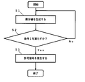
- FIG. 6 is a flowchart showing an example of a processing procedure performed by the defibrillation electric device according to the second embodiment of the present invention.
- the defibrillation electric device of the present invention is a defibrillation electric device including an electrocardiographic waveform input unit and a permission signal generation unit, and is an electrocardiographic waveform obtained from a human body and input from the electrocardiographic waveform input unit. It is characterized in that the permission signal is controlled to be generated from the permission signal generation unit after the peak of the event presumed to be the R wave of the above is exceeded and after the following condition 1 is satisfied. It is a thing. (Condition 1) differential value generated from the events that are estimated with the R-wave is less than negative constant C 3 value.
- the defibrillation electric device has a threshold value with respect to the differential value of the event estimated to be the R wave of the portion corresponding to the descending phase after the peak of the event estimated to be the R wave of the electrocardiographic waveform is exceeded. (Negative constant C 3 value) is provided, and there has been no conventional electric device for defibrillation having this configuration. Further, by providing the above configuration, it becomes easy to determine whether or not the waveform to be applied is an R wave, and it is possible to easily avoid the application of a voltage due to erroneous detection of the R wave.
- FIG. 1 is a schematic view showing a configuration of a defibrillation catheter system including an electric device for defibrillation according to the first embodiment of the present invention.
- FIG. 2 is a diagram showing an example of an electrocardiographic waveform displayed on a display unit (not shown) of an electrocardiograph and a differential waveform which is a collection of differential values of the electrocardiographic waveform.
- the horizontal axis of the electrocardiographic waveform in FIG. 2 indicates time (seconds), and the vertical axis indicates voltage difference (mV).
- the broken line C 1 extending in the time axis direction of the differential waveform in FIG. 2 is a line whose vertical axis value (differential value) is a positive constant C 1
- the broken line C 2 extending in the time axis direction is the vertical axis value (differential value).
- the value) is a line having a positive constant C 2 value
- the broken line C 3 extending in the time axis direction is a line having a value (differential value) on the vertical axis having a negative constant C 3 value.
- the solid line B extending in the time axis direction is the baseline of the differential waveform.
- FIG. 3 is a diagram showing another example of the differential waveform, which is a collection of the differential values of the electrocardiographic waveform.
- the defibrillation electric device 2 of FIG. 1 includes an electrocardiographic waveform input unit 3 and a permission signal generation unit 7.
- an electrocardiographic waveform obtained from a body surface electrode 19 arranged on the surface of the human body is input from an electrocardiographic waveform input unit 3 via an electrocardiograph 40 or the like. It has become like.
- the defibrillation electric device 2 has a permission signal after the peak 51p of the event 51 estimated to be the R wave of the electrocardiographic waveform 50 as shown in FIG. 2 is exceeded and the following condition 1 is satisfied. It is controlled so as to generate a permission signal from the generation unit 7. (Condition 1) differential value generated from the event 51, which is estimated as R-wave is less than negative constant C 3 value.
- the differential waveform 60 of FIG. 2 is an example of an aggregate of differential values generated from the electrocardiographic waveform 50, and the negative wave 61N of the differential waveform 60 is the peak of the event 51 estimated to be the R wave of the electrocardiographic waveform 50. It corresponds to a set of differential values generated from the event 51 estimated to be the R wave of the descending phase 51d after 51p.
- the G point of the differential waveform 60 corresponds to the time when the differential value reaches the negative constant C 3 value, and the defibrillation electric device 2 may be controlled so as to generate the permission signal at the timing after the G point. .. In FIG.
- the defibrillation electric device 2 is controlled so as to generate a permission signal before the peak 61b of the negative wave 61N. This makes it easier to complete defibrillation within the absolute refractory period.
- the defibrillation electric device 2 is preferably controlled so as to generate a permission signal within 60 msec from when the differential value reaches the negative constant C 3 value (point G), and within 50 msec. It is more preferable that the permission signal is generated, and it is more preferable that the permission signal is generated within 10 ms. When the differential value reaches the negative constant C 3 value. It is particularly preferable that the permission signal is controlled to be generated.
- the peak 61b of the negative wave 61N corresponds to the inflection point 51c in the descending phase 51d of the event 51 estimated to be the R wave.
- the permission signal is not particularly limited as long as it is a signal related to the application of a voltage for defibrillation. Examples thereof include a switch-on permission signal for the switching unit 10.
- the permission signal generation unit 7 may generate at least one of these permission signals.
- some of these permission signals may be generated by the operation of the operation unit 6 described later.
- the permission signal generation unit 7 is not limited to the arithmetic processing control unit 8 described later, and may be provided in the power supply unit 9 or the like.
- Examples of the differential value generated from the event 51 estimated to be the R wave include a differential value obtained through a differentiating circuit 4 described later, a differential value obtained by a general differential calculation, and the like. Further, the differential value generated from the event 51 estimated to be the R wave is preferably a first-order differential value. Since the time until the first derivative value is generated is shorter than that of the second derivative value, the time from the acquisition of the electrocardiographic information to the generation of the permission signal can be shortened.
- the negative constant C 3 value is, for example, a value lower than the value (differential value) on the vertical axis of the baseline B in the differential waveform 60 of FIG.
- the value (differential value) on the vertical axis of the baseline B is the same as the value (differential value) on the vertical axis of the O point of the differential waveform 60, which is a portion corresponding to the peak 51p of the event 51 estimated to be the R wave. be.
- the negative constant C 3 value may be a different value depending on the type of the differentiating circuit 4 or the like.
- the electrocardiographic waveform 50 is preferably a waveform obtained by lead II, which makes it easy to detect an event presumed to be an R wave.
- the electrocardiographic waveform 50 is not limited to the second lead, and may be obtained by other leads depending on the orientation of the patient's heart.
- the electrocardiographic waveform 50 is V1 lead, V2 lead, V3 lead, V4 lead, V5 lead, V6 lead, I lead, II lead, III lead, aVR lead, It may be a waveform obtained by aVL lead or aVF lead.
- the electrocardiographic waveform 50 may be an average waveform of two or more leads, an average waveform of three or more leads, or an average waveform of 12 leads.
- a differential waveform which is a collection of differential values generated from the event 51 estimated to be the R wave in the portion corresponding to the rising phase 51r before the peak 51p of the event 51 estimated to be the R wave (hereinafter, is simply referred to as "positive wave 61P" peak value of) the positive constant C 1 value or more.
- the waveform to be applied is an R wave because the defibrillation electric device 2 is provided with a threshold value (positive constant C 1 value) for the peak value of the positive wave 61P as in the above condition 2. Therefore, it is possible to easily avoid the application of the voltage due to the erroneous detection of the R wave.
- the positive constant C 1 value is, for example, a value that exceeds the value (differential value) on the vertical axis of the baseline B in the differential waveform 60 of FIG. Further, the positive constant C 1 value may be a different value depending on the type of the differentiating circuit 4 or the like.
- the defibrillation electric device 2 is controlled so as to satisfy the above condition 2 and the following condition 3 and to generate a permission signal after the above condition 1 is satisfied.
- Condition 3 In the positive wave 61P, the time when the differential value is equal to or more than the positive constant C 2 value smaller than the C 1 value is measured, and the time is 10 msec or more and 80 msec or less.
- the defibrillation electric device 2 is provided with a threshold value related to the upper limit of the time when the differential value in the positive wave 61P is equal to or more than the positive constant C 2 value as in the above condition 3, so that the erroneous detection of the R wave can be detected. It can be easily avoided.
- the differential waveform 62 generated from the patient's T wave 52 may be similar to the differential waveform 61 generated from the event 51 presumed to be the R wave, but due to the above threshold, the above condition 3 It is possible to easily exclude the differential waveform 62 derived from the T wave 52, which has a long time specified in the above, from the application target of the voltage.
- the time is more preferably 70 msec or less, still more preferably 60 msec or less.
- the time is 10 msec or more, it is possible to easily exclude high frequency noise having a short peak width. As a result, the detection sensitivity of the R wave can be improved.
- the time is more preferably 15 msec or more, still more preferably 20 msec or more.
- the positive constant C 2 value is, for example, a value that exceeds the value (differential value) on the vertical axis of the baseline B in the differential waveform 60 of FIG. Further, the positive constant C 2 value may be a different value depending on the type of the differentiating circuit 4 or the like.
- the defibrillation electric device 2 may be controlled so as not to satisfy the condition 2 and to generate a permission signal after the conditions 3 and 1 are satisfied.
- the defibrillation electric device 2 is controlled so as to satisfy the following condition 4 and to generate a permission signal after the condition 1 is satisfied.
- (Condition 4) events that are estimated to R-wave hereinafter, simply referred to as "R n wave"
- R n-1 wave events that are estimated to previous R-wave than
- FIG. 3 is a diagram showing another example of the differential waveform, which is a collection of the differential values of the electrocardiographic waveform.
- Differential waveform of FIG. 3 60 electrocardiographic waveform R n wave and the differential waveform n is an aggregate of the differential values generated from the (not shown), R n-1 wave immediately preceding than R n wave It has a differential waveform n-1 which is a collection of differential values generated from (not shown).
- the condition 4 is satisfied from the point G n-1 where the value (differential value) on the vertical axis of the differential waveform n-1 reaches the negative constant C 3 value, on the vertical axis of the differential waveform n.
- the time until the G n point where the value (differential value) reaches the negative constant C 3 value (hereinafter, may be referred to as G n-1 ⁇ G n time) is 50 msec or more. ..
- the G n-1- G n time is more preferably 100 msec or more, further preferably 200 msec or more, still more preferably 240 msec or more, and particularly preferably 260 msec or more.
- the upper limit of G n-1 ⁇ G n time is not particularly limited, but may be, for example, 2 seconds or less, 1 second or less, 800 ms or less, or 600 ms or less. It may be 400 ms or less, or 350 ms or less.
- the defibrillation electric device 2 may be controlled so as to generate a permission signal after at least one of the conditions 2 and 3, the condition 4 and the condition 1 are satisfied.
- the defibrillation electric device 2 is controlled so as to satisfy the following condition 5 and to generate a permission signal after the condition 1 is satisfied.
- Condition 5 The time from the O point of the differential waveform 60, which is the part corresponding to the peak 51p of the event 51 estimated to be the R wave, to the G point where the differential value reaches the negative constant C 3 value is measured. The time is 2 (msec) or more and 20 (msec) or less.
- the defibrillation electric device 2 is provided with a threshold value for the time from the O point to the G point of the differential waveform 60 as in the above condition 5, so that it is easy to avoid erroneous detection of the R wave. can.
- the defibrillation electric device 2 is such that the permission signal is generated after at least one condition selected from the group consisting of condition 2, condition 3, and condition 4, and condition 5 and condition 1 are satisfied. It may be controlled.
- the negative constant C 3 value, the positive constant C 2 value, the positive constant C 1 value, the threshold value of G n-1 ⁇ G n time, and the threshold value of the time from point O to point G will be described later. It is preferably stored in the memory or set in the comparator. Further, these do not have to be stored in the same memory, and may be stored in different memories. Further, these do not have to be stored in the same comparator, and may be stored in different comparators.
- FIG. 4 is a block diagram of the defibrillation catheter system 1 including the defibrillation electrical device 2 according to the first embodiment.
- the electrocardiographic information obtained from the body surface electrodes 19 arranged on the body surface of the human body is transmitted to the electrocardiograph 40 via the first lead wire 31. It has become.
- the electrode for acquiring electrocardiographic information is not limited to the body surface electrode, and may be an electrode for measuring the intracardiac potential, but the body surface electrode is preferable because it has excellent R wave detection sensitivity.
- As the body surface electrode a 12-lead electrode is preferable.
- the defibrillation electric device 2 of FIGS. 1 and 4 includes a first connection portion 11 connected to a plurality of electrodes provided on the distal side of the catheter 20 and a second connection portion 12 connected to the electrocardiograph 40. It has a power supply unit 9 that generates an applied voltage, and a switching unit 10 that is connected to the power supply unit 9 and switches to an application mode in which a voltage is applied. Further, the first connection unit 11 is connected to the power supply unit 9 via the switching unit 10, and the first connection unit 11 is connected to the second connection unit 12 without passing through the switching unit 10. Since the first connecting portion 11 is connected to the second connecting portion 12 without passing through the switching portion 10, the local potential at each electrode can be measured even during defibrillation.
- the defibrillation electric device 2 includes an electrocardiographic waveform input unit 3, and the electrocardiogram waveform information output from the electrocardiograph 40 is internally transmitted from the electrocardiographic waveform input unit 3 via the second conductor 32 or the like. It is supposed to be entered.
- the electrocardiographic waveform input unit 3 is not particularly limited, but is preferably one that can withstand a discharge of 5 kV input via a resistor of 50 ⁇ .
- the electrocardiographic waveform input from the electrocardiographic waveform input unit 3 is transmitted to the arithmetic processing control unit 8 through the differentiating circuit 4.
- the arithmetic processing control unit 8 determines whether or not the transmitted differential waveform 60 satisfies the condition related to the threshold value such as the negative constant C 3 value stored in the memory 5, that is, whether or not the condition 1 or the like is satisfied, and satisfies the condition 1 or the like.
- the permission signal generation unit 7 in the arithmetic processing control unit 8 can generate a voltage application permission signal.
- the permission signal is transmitted to the power supply unit 9, and DC voltages having different polarities, positive and negative, can be applied to the first electrode group 21 and the second electrode group 22.
- the energization waveform may be biphasic in which the polarity is reversed in the middle, or monophasic in which the polarity is constant, but it is said that biphasic can be stimulated with less energy. Therefore, it is preferable.
- the energizing energy applied to the living body can be set to, for example, 1 J or more and 30 J or less.
- the defibrillation electric device 2 may have a display unit for displaying an electrocardiographic waveform, and a mark is displayed on the display unit for an event presumed to be an R wave. It may be.
- the description of the display unit 73 of the second embodiment can be referred to.
- the power supply unit 9 includes, for example, a power supply, a booster circuit for boosting a DC voltage, a charging circuit, a capacitor for charging the applied voltage, a waveform generation circuit for generating a pulse voltage, and the like. At least a part of these may be provided outside the power supply unit 9.
- the position of the power supply unit 9 is not particularly limited, and may be provided outside the arithmetic processing control unit 8 as shown in FIG. 4, or may be provided inside the arithmetic processing control unit 8.
- the permission signal generation unit 7 in the arithmetic processing control unit 8 is controlled to generate the switch-on permission signal. good.
- the permission signal is transmitted to the first switch 10A and the second switch 10B of the switching unit 10, and the first switch 10A and the second switch 10B can be changed from the off state to the on state, whereby the first electrode group 21 , The second electrode group 22 can be energized.
- the switch constituting the switching unit 10 is in the off state, the first electrode group 21 and the second electrode group 22 are insulated from the power supply unit 9, so that defibrillation is not performed.
- the intracardiac potential can be measured using the first electrode group 21 and the second electrode group 22.
- At least one of the functions of the defibrillation electric device 2 for example, an electrocardiographic waveform input unit 3, a differentiating circuit 4, a memory 5, a permission signal generation unit 7, an arithmetic processing control unit 8, a power supply unit 9, and a switching unit 10.
- the function may be realized by hardware or software. Examples of the hardware include logic circuits formed in integrated circuits such as LSI (Large Scale Integration), ASIC (Application Specific Integrated Circuit), and FPGA (Field-Programmable Gate Array).
- the defibrillation electric device 2 realizes at least one of the functions of an electrocardiographic waveform input unit 3, a differentiating circuit 4, a memory 5, a permission signal generation unit 7, an arithmetic processing control unit 8, a power supply unit 9, and a switching unit 10.
- You may have a computer that executes the instructions of the program, which is the software for doing so.
- the computer preferably includes a processor and a computer-readable recording medium that stores the program.
- the above functions are realized by the processor executing a program stored in a computer-readable recording medium.
- a processor a CPU (Central Processing Unit) can be used.
- a recording medium a ROM (Read Only Memory) or the like can be used.
- the recording medium may include a RAM (Random Access Memory).
- the program may be supplied to the computer via any transmission medium capable of transmitting the program. Examples of the transmission medium include a communication network and a communication line.
- the definement electric device 2 shown in FIGS. 1 and 3 is used to perform various operations such as starting and stopping the definement electric device 2, setting the amount of applied energy, charging, applying a voltage, and selecting an applied electrode.
- the operation unit 6 is provided.
- known input means such as a button switch and a lever can be used.
- the operation unit 6 is preferably connected to the arithmetic processing control unit 8, whereby the input signal from the operation unit 6 is transmitted to the arithmetic processing control unit 8.
- the permission signal of a part of the above permission signals may be generated by the operation of the operation unit 6.
- the first electrode group 21 and the second electrode group 22 are preferably connected to the electrocardiograph 40 without going through the switching unit 10, and are connected to the electrocardiograph 40 without going through any switch unit. Is more preferable. As a result, the first electrode group 21 and the second electrode group 22 can be constantly connected to the electrocardiograph 40, while checking the intracardiac potential displayed on the display unit (not shown) of the electrocardiograph 40. Each procedure can be facilitated.
- the switching unit 10 may have one or two or more switches. As shown in FIG. 4, the switching unit 10 preferably has a plurality of first switches 10A connected in parallel to each other and a plurality of second switches 10B connected in parallel to each other.
- the first electrode group 21 is connected to the power supply unit 9 via the first switch 10A, respectively, and the second electrode group
- each of the 22 is connected to the power supply unit 9 via the second switch 10B. That is, it is preferable that the first electrode group 21 and the second electrode group 22 are connected to the power supply unit 9 via different switches.
- each electrode group can be electrically separated, so that the intracardiac potential can be acquired independently for each electrode group.
- the defibrillation electric device 2 has a third electrode group 23, which is a dedicated electrode for measuring the intracardiac potential, on the proximal side of the first electrode group 21 and the second electrode group 22. May be. Since the third electrode group 23 is located on the proximal side, it can be arranged at a position corresponding to, for example, the ascending aorta. It is preferable that the third electrode group 23 is not connected to the power supply unit 9. This makes it easier to use the third electrode group 23 as a dedicated electrode for measuring the intracardiac potential.
- the number of electrodes constituting each electrode group is not particularly limited, and each electrode group may be the same or different. Above all, it is preferable that the number of electrodes constituting the first electrode group 21 and the number of electrodes constituting the second electrode group 22 are the same. Thereby, the surface areas of the first electrode group 21 and the second electrode group 22 can be easily made the same. By having the same surface area of each first electrode group 21 and each second electrode group 22 and evenly arranging the same number of electrodes, efficient defibrillation can be performed and intracardiac electrocardiogram measurement can be performed. The accuracy of can be improved.
- the number of electrodes constituting the third electrode group 23 is preferably less than or equal to the number of electrodes constituting the first electrode group 21 and the number of electrodes constituting the second electrode group 22.
- the number of electrodes in the first electrode group 21 and the second electrode group 22 can be eight, and the number of electrodes in the third electrode group 23 can be four.
- Each electrode group preferably exists in a region of half or more of the outer circumference of the resin tube 27, and more preferably formed in a ring shape.
- Each electrode group may contain a conductive material such as platinum or stainless steel, but in order to make it easier to grasp the position of the electrode under fluoroscopy, it contains an X-ray opaque material such as platinum. It is preferable to have.
- a tip tip 25 may be provided at the distal end of the catheter 20.
- the tip tip 25 preferably has a tapered portion whose outer diameter decreases toward the distal side.
- the tip 25 may be made of a conductive material.
- the tip 25 can function as an electrode.
- the tip tip 25 may be made of a polymer material, and the hardness of the tip tip 25 may be lower than the hardness of the resin tube 27 in order to protect the internal tissue from contact with the catheter 20.
- An operation wire or a spring member for bending the distal side of the catheter 20 may be arranged in the lumen of the resin tube 27. Specifically, the distal end of the operating wire is fixed to the distal end of the resin tube 27 or the tip 25, and the proximal end of the operating wire is fixed to the handle 26, which will be described later. preferable.
- the third conductor 33 (lead wire) is connected to each electrode group.
- the other end of the third conductor 33 connected to the first electrode group 21 and the second electrode group 22 is preferably connected to the first connection portion 11 of the defibrillation electric device 2.
- the other end of the third conductor 33 connected to the third electrode group 23 is preferably connected to the third connection portion 13 of the defibrillation electric device 2.
- the third conductor 33 may be a plurality of conductors connected by a connecting member such as a connector.
- the third connecting portion 13 and the fourth connecting portion 14 are connected via the seventh conducting wire 37.
- the seventh conductor 37 may be a wiring material or may be a part of a wiring pattern provided on the printed circuit board.
- the first connecting portion 11 and the switching portion 10 are connected via the fifth conducting wire 35.
- the first electrode group 21 and the second electrode group 22 are connected to the power supply unit 9, so that a voltage can be applied.
- the first electrode group 21, the second electrode group 22, and the power supply unit 9 may be connected via different connecting members such as connectors.
- the second connection portion 12 is connected to the other end of the fourth conductor 34 connected to the input terminal of the electrocardiograph 40 corresponding to the first electrode group 21 and the second electrode group 22. Further, it is preferable that the second connecting portion 12 is connected to the fifth conducting wire 35 by the sixth conducting wire 36. It is preferable that the fifth conductor 35 and the sixth conductor 36 are not provided with a switch portion. As a result, the intracardiac potential can be measured through the first electrode group 21 and the second electrode group 22 even during defibrillation.
- the fifth conductor 35 and the sixth conductor 36 may be a wiring material or may be a part of a wiring pattern provided on the printed circuit board.
- a handle 26 that the user grips when operating the catheter 20 may be provided on the proximal side of the resin tube 27.
- the shape of the handle 26 is not particularly limited, but in order to alleviate the stress concentration at the connection point between the resin tube 27 and the handle 26, the handle 26 may be formed in a cone shape in which the outer diameter decreases toward the distal side. preferable.
- the electrocardiograph 40 measures the intracardiac potential through various electrodes.
- a known electrocardiograph 40 can be used.
- the defibrillation electric device 2 may have an electrode selection switch for selecting an electrode to which a voltage is applied. As a result, electrical stimulation can be applied only to specific electrodes.
- the position where the electrode selection switch is provided is not particularly limited, but it is preferable that the electrode selection switch is connected to the power supply unit 9, and it is more preferable that the electrode selection switch is provided in the arithmetic processing control unit 8.
- the electrode selection switch may be provided separately from the switches constituting the switching unit 10 (for example, the first switch 10A and the second switch 10B), and at least one of the switches constituting the switching unit 10 is the electrode selection switch. You may. Further, although not shown, the definement electric device 2 may be provided with a safety switch.
- the safety switch is preferably connected between the switching unit 10 and the power supply unit 9, and more preferably connected between the arithmetic processing control unit 8 and the switching unit 10.
- the definement electric device 2 may be provided with a protection circuit that absorbs a high voltage generated when the switch is shut off. As a result, damage to each switch can be prevented.
- the defibrillation electric device 2 may be provided with an overvoltage protection circuit that protects the electrocardiograph 40 from overvoltage between the power supply unit 9 and the electrocardiograph 40.
- the definement electric device 2 may have an impedance measurement circuit.
- the impedance measurement circuit is preferably connected, for example, between the first electrode group 21 and the second electrode group 22 so as to measure the impedance between the first electrode group 21 and the second electrode group 22.
- FIG. 5 is a block diagram of the defibrillation electric device 70 according to the second embodiment.
- the same components as those of the definement electric device 2 according to the first embodiment are designated by the same reference numerals, and the description thereof will be omitted.
- the electrocardiographic information input from the electrocardiographic waveform input unit 3 is the A / D converter 71 and the first arithmetic processing control unit. It is preferable that the electrocardiographic waveform is displayed on the display unit 73 after passing through 72 (CPU). On the other hand, the electrocardiographic information input from the electrocardiographic waveform input unit 3 passes through the differentiating circuit 4 to generate a differential waveform. Next, the differential waveform is transmitted to the comparator 74 (comparator) in which a negative constant C 3 value or the like is set, and if condition 1 or the like is satisfied, the signal is transmitted to the second arithmetic processing control unit 75 (FPGA).
- the comparator 74 comparativator
- a mark display signal is generated from the second arithmetic processing control unit 75 (FPGA), and after the mark display signal is transmitted to the first arithmetic processing control unit 72 (CPU), it is estimated to be an R wave on the display unit 73. It is preferable that a mark is displayed for the event. Examples of the shape of the mark include a polygon such as a circle, a triangle, and a quadrangle, and a linear shape. Examples of the position where the mark is displayed include the peak of an event presumed to be an R wave. Further, the mark display signal may be generated from the first arithmetic processing control unit 72 (CPU) as long as the mark is displayed on the display unit 73 for an event presumed to be an R wave.
- the defibrillation electric device 70 includes a display unit 73 that displays an electrocardiographic waveform, and after the peak of an event presumed to be an R wave is exceeded and after the following condition 1 is satisfied, It is preferable that the display unit 73 is controlled so that the mark display signal for adding a mark to the event presumed to be an R wave is generated from the mark display signal generation unit 76.
- the mark is added to the event presumed to be the R wave on the display unit 73 in this way, the operator can visually confirm the state of the R wave.
- (Condition 1) differential value generated from the events that are estimated to R-wave is less than negative constant C 3 value.
- a differential waveform that is a collection of differential values generated from an event estimated to be an R wave in a portion corresponding to an ascending phase before the peak of an event estimated to be an R wave (hereinafter, simply "positive". peak to as wave 61P ”) is positive constant C 1 value or more.
- the defibrillation electric device 70 is controlled so that the mark display signal is generated after the conditions 2 and the following condition 3 are satisfied and the condition 1 is satisfied. (Condition 3) In the positive wave 61P, the time when the differential value is C 2 value or more smaller than C 1 value is measured, and the time is 10 msec or more and 80 msec or less.
- the defibrillation electric device 70 is controlled so that the mark display signal is generated after the following condition 4 is satisfied and the condition 1 is satisfied.
- (Condition 4) events that are estimated to R-wave hereinafter, simply referred to as "R n wave"
- R n-1 wave differentiated value after reaching C 3 value generated from that
- the description of the defibrillation electric device 2 according to the first embodiment can be referred to.
- the definement electric device 70 can switch the inside of the second arithmetic processing control unit 75 (FPGA) from the non-permission mode to the permission mode by operating the operation unit 6. .. Further, at the same time as switching the mode, the applied energy amount may be set, the applied energy may be charged to the capacitor, or the charging may be completed. You may be. Further, the pulse voltage may be automatically generated after the charging is completed.
- the non-permission mode is a mode in which the permission signal related to defibrillation is not generated even if the above condition 1 and the like are satisfied
- the permission mode is a mode in which the permission signal related to defibrillation is generated when the above condition 1 and the like are satisfied.
- the permission signal related to defibrillation is not particularly limited as long as it is a signal related to application of a voltage for definement, and for example, a permission signal for charging the power supply unit 9, a permission signal for generating a pulse voltage, and a voltage application. Examples include a permission signal, a switch-on permission signal for the switching unit 10, and the like. Other details regarding the permit signal relating to defibrillation can be referred to in the description of the first embodiment.
- the electrocardiographic information input from the electrocardiographic waveform input unit 3 passes through the differentiating circuit 4 to generate a differential waveform, and the differential waveform is a negative constant C 3 value or the like.
- the set comparator 74 component
- a signal is transmitted to the second arithmetic processing control unit 75 (FPGA), and the second arithmetic processing control unit 75 (FPGA) transmits the signal. It is preferable that the permission signal is generated.
- the period from the electrocardiographic waveform input unit 3 to the permission signal generation unit 7 is composed of a hardware circuit. Since the hardware circuit is a circuit in which signal processing is not performed by software, signal processing is accelerated. As a result, the time from the acquisition of the electrocardiographic information to the generation of the permission signal can be shortened.
- the signal from the electrocardiographic waveform input unit 3 to the permission signal generation unit 7 may be an analog signal or a digital signal.
- the defibrillation electric device 70 for example, the electrocardiographic waveform input unit 3, the differentiating circuit 4, the comparator 74, the permission signal generation unit 7, the first arithmetic processing control unit 72, and the second
- the functions of the arithmetic processing control unit 75, the arithmetic processing control unit 8, the power supply unit 9, the switching unit 10, and the like may be realized by hardware or software.
- the description of the first embodiment can be referred to.
- FIG. 6 is a flowchart showing an example of a processing procedure performed by the defibrillation electric device 70.
- the differentiating circuit 4 generates a differentiating wave value based on the electrocardiographic information input from the electrocardiographic waveform input unit 3 (step S1).
- the comparator 74 (comparator) in which the negative constant C 3 value or the like is set determines whether or not the differential value satisfies the condition 1 (step S2).
- the comparator 74 transmits a signal to the second arithmetic processing control unit 75 (FPGA), and when the condition 1 is not satisfied, the comparator 74 uses the second arithmetic processing control unit 75. No signal is transmitted to (FPGA).
- the second arithmetic processing control unit 75 (FPGA) generates an authorization signal based on the above signal (step S3).
- the second arithmetic processing control unit 75 (FPGA) corresponds to the permission signal generation unit 7.
- the method for generating a defibrillation signal determines whether or not the following condition 1 is satisfied after the peak 51p of the event 51 estimated to be an R wave is exceeded in the electrocardiographic waveform 50 obtained from the human body. It has a step to generate a permission signal and a step to generate a permission signal after the condition 1 is satisfied. (Condition 1) differential value generated from the event 51, which is estimated as R-wave is less than negative constant C 3 value.
- the defibrillation signal generation method preferably further includes a step of determining whether or not the following condition 2 is satisfied.
- Condition 2 A differential waveform which is a collection of differential values generated from the event 51 estimated to be the R wave in the portion corresponding to the rising phase 51r before the peak 51p of the event 51 estimated to be the R wave (hereinafter, is simply referred to as "positive wave 61P" peak value of) the positive constant C 1 value or more.
- the defibrillation signal generation method preferably further includes a step of determining whether or not the following condition 3 is satisfied. (Condition 3) In the positive wave 61P, the time when the differential value is equal to or greater than the positive constant C 2 value smaller than the positive constant C 1 value is measured, and the time is 10 msec or more and 80 msec or less.
- the defibrillation signal generation method preferably further includes a step of determining whether or not the following condition 4 is satisfied.
- Condition 4 events that are estimated to R-wave (hereinafter, simply referred to as "R n wave”), wherein the events that are estimated to previous R-wave than (hereinafter, simply "R n-1 wave” differentiated value after reaching C 3 value generated from that), to measure the time until the differential values generated from R n wave reaches the C 3 value is the time at least 50m seconds.
- the method for generating a defibrillation signal includes at least one condition selected from the group consisting of the above conditions 2, 3, and 4, and a step of generating a permission signal after the above condition 1 is satisfied. Is preferable.
- the method of generating the defibrillation signal is a step of determining whether or not the following condition 1 is satisfied after exceeding the peak 51P of the event 51 estimated to be an R wave in the electrocardiographic waveform obtained from the human body, and satisfying the condition 1.
- the display unit 73 has a step of generating a mark display signal for giving a mark to the event 51 presumed to be an R wave, and a permission signal is generated after the step of generating the mark display signal. It is preferable that the device has a step to cause the wave. (Condition 1) differential value generated from the event 51, which is estimated as R-wave is less than negative constant C 3 value.
- the mark attached to an event presumed to be an R wave can be used as a mark to visually check the RR interval and the like to check the heart. After grasping the state, it is possible to switch the defibrillation non-permission mode to the permission mode. This makes it easier to defibrillate and enhances safety.
- the defibrillation signal is generated for the step of determining whether or not the following condition 2 is satisfied, and for the event 51 which is estimated to be an R wave on the display unit 73 after the condition 2 is satisfied and the condition 1 is satisfied. It is preferable to have a step of generating a mark display signal for giving a mark.
- a differential waveform which is a collection of differential values generated from an event 51 estimated to be an R wave in a portion corresponding to an ascending phase before the peak 51P of an event 51 estimated to be an R wave (hereinafter referred to as a differential waveform).
- peak value of simply referred to as "positive wave 61P” is positive constant C 1 value or more.
- the defibrillation signal generation method includes a step of determining whether or not the following condition 3 is satisfied, and an event estimated to be an R wave on the display unit 73 after the conditions 2 and 3 are satisfied and the condition 1 is satisfied. It is preferable to have a step of generating a mark display signal for giving a mark to 51. (Condition 3) In the positive wave 61P, the time when the differential value is equal to or more than the positive constant C 2 value smaller than the C 1 value is measured, and the time is 10 msec or more and 80 msec or less.
- the defibrillation signal generation method preferably includes at least one condition selected from the group consisting of the above conditions 2 and 3 and a step of generating a mark display signal after the above condition 1 is satisfied. ..
- the defibrillation signal is generated for the step of determining whether or not the following condition 4 is satisfied, and for the event 51 which is estimated to be an R wave on the display unit 73 after the condition 4 is satisfied and the condition 1 is satisfied. It is preferable to have a step of generating a mark display signal for giving a mark.
- R n wave events that are estimated to R-wave
- R n-1 wave differentiated value after reaching C 3 value generated from that
- the defibrillation signal generation method includes at least one condition selected from the group consisting of the above condition 2, condition 3, and condition 4, and a step of generating a mark display signal after the above condition 1 is satisfied. Is preferable.
- the defibrillation electric device 2 the differentiating circuit of the definement electric device 70, the arithmetic processing control unit, the memory, the comparator, the power supply unit, and the like are used. It can be executed by using it.
- the description of each condition of the definement electric device 2 and the definement electric device 70 can be referred to.
- the defibrillation signal generation method does not need to execute each step in one defibrillation electric device, and may be executed in separate devices.
- Electrocardiographic waveform input unit 4 Electric device for defibrillation 3: Electrocardiographic waveform input unit 4: Differentiation circuit 5: Memory 6: Operation unit 7: Allowed signal generation unit 8: Arithmetic processing control unit 9: Power supply unit 10: Switching unit 10A: 1st switch 10B: 2nd switch 11: 1st connection unit 12: 2nd connection unit 13: 3rd connection unit 14: 4th connection unit 19: Body surface electrode 20: Waveform 21: 1st electrode group 22: 2nd electrode group 23: 3rd electrode group 25: Tip tip 26: Handle 27: Resin tube 31: 1st lead wire 32: 2nd lead wire 33: 3rd lead wire 34: 4th lead wire 35: 5th lead wire 36: 6th lead 37: 7th lead 40: Electrocardiograph 50: Electrocardiographic waveform 51: Event estimated to be R wave 51c: Defibrillation point 51d in the descending phase of the event estimated to be R wave: Estimated to be R wave Falling phase of the event 51p
Landscapes
- Health & Medical Sciences (AREA)
- Life Sciences & Earth Sciences (AREA)
- Cardiology (AREA)
- Heart & Thoracic Surgery (AREA)
- Engineering & Computer Science (AREA)
- Public Health (AREA)
- Biomedical Technology (AREA)
- Veterinary Medicine (AREA)
- General Health & Medical Sciences (AREA)
- Animal Behavior & Ethology (AREA)
- Molecular Biology (AREA)
- Physics & Mathematics (AREA)
- Medical Informatics (AREA)
- Surgery (AREA)
- Biophysics (AREA)
- Pathology (AREA)
- Radiology & Medical Imaging (AREA)
- Nuclear Medicine, Radiotherapy & Molecular Imaging (AREA)
- Physiology (AREA)
- Psychiatry (AREA)
- Artificial Intelligence (AREA)
- Computer Vision & Pattern Recognition (AREA)
- Signal Processing (AREA)
- Vascular Medicine (AREA)
- Electrotherapy Devices (AREA)
Priority Applications (4)
| Application Number | Priority Date | Filing Date | Title |
|---|---|---|---|
| CN202180016891.8A CN115190810B (zh) | 2020-03-09 | 2021-01-22 | 除颤用电气装置以及除颤信号的产生方法 |
| JP2022505818A JP7769602B2 (ja) | 2020-03-09 | 2021-01-22 | 除細動用電気装置、及び除細動用装置の作動方法 |
| KR1020227029448A KR20220148178A (ko) | 2020-03-09 | 2021-01-22 | 제세동용 전기 장치, 및 제세동 신호의 발생 방법 |
| US17/900,947 US20220409912A1 (en) | 2020-03-09 | 2022-09-01 | Electric device for defibrillation, and method for generating defibrillation signal |
Applications Claiming Priority (2)
| Application Number | Priority Date | Filing Date | Title |
|---|---|---|---|
| JP2020040144 | 2020-03-09 | ||
| JP2020-040144 | 2020-03-09 |
Related Child Applications (1)
| Application Number | Title | Priority Date | Filing Date |
|---|---|---|---|
| US17/900,947 Continuation US20220409912A1 (en) | 2020-03-09 | 2022-09-01 | Electric device for defibrillation, and method for generating defibrillation signal |
Publications (1)
| Publication Number | Publication Date |
|---|---|
| WO2021181912A1 true WO2021181912A1 (ja) | 2021-09-16 |
Family
ID=77671348
Family Applications (1)
| Application Number | Title | Priority Date | Filing Date |
|---|---|---|---|
| PCT/JP2021/002247 Ceased WO2021181912A1 (ja) | 2020-03-09 | 2021-01-22 | 除細動用電気装置、及び除細動信号の発生方法 |
Country Status (5)
| Country | Link |
|---|---|
| US (1) | US20220409912A1 (https=) |
| JP (1) | JP7769602B2 (https=) |
| KR (1) | KR20220148178A (https=) |
| CN (1) | CN115190810B (https=) |
| WO (1) | WO2021181912A1 (https=) |
Citations (5)
| Publication number | Priority date | Publication date | Assignee | Title |
|---|---|---|---|---|
| JPS59500895A (ja) * | 1982-05-28 | 1984-05-24 | ミロ−スキ ミエツチスラ−フ | 心拍数検出装置 |
| JP2002524160A (ja) * | 1998-09-03 | 2002-08-06 | カーディアック・ペースメイカーズ・インコーポレーテッド | 心房ペーシングが存在するときに心房不整頻搏を電気除細動する方法および電気除細動機 |
| JP2014217636A (ja) * | 2013-05-10 | 2014-11-20 | 日本ライフライン株式会社 | 心腔内除細動カテーテルシステム |
| JP2017176351A (ja) * | 2016-03-29 | 2017-10-05 | フクダ電子株式会社 | 除細動器 |
| WO2019155942A1 (ja) * | 2018-02-07 | 2019-08-15 | 株式会社カネカ | 除細動カテーテルシステム、除細動用電源装置および除細動用電源装置の制御方法 |
Family Cites Families (18)
| Publication number | Priority date | Publication date | Assignee | Title |
|---|---|---|---|---|
| US5423325A (en) * | 1993-03-12 | 1995-06-13 | Hewlett-Packard Corporation | Methods for enhancement of HRV and late potentials measurements |
| JP2008104640A (ja) * | 2006-10-25 | 2008-05-08 | Toshiba Corp | 超音波診断装置、心拍同期信号生成装置及び心拍同期信号生成方法 |
| JP2010125303A (ja) * | 2008-11-28 | 2010-06-10 | Ippei Tanaka | 低周波治療装置 |
| JPWO2012023399A1 (ja) | 2010-08-19 | 2013-10-28 | 株式会社日立メディコ | 医用画像診断装置及び心臓計測値表示方法 |
| CN105326498A (zh) * | 2011-09-08 | 2016-02-17 | Apn健康有限责任公司 | R波检测方法 |
| KR20130087940A (ko) * | 2012-01-30 | 2013-08-07 | 동서대학교산학협력단 | 심박변이도 계측방법 및 그를 위한 계측장치 |
| CN102894970B (zh) * | 2012-10-22 | 2014-05-07 | 深圳邦健生物医疗设备股份有限公司 | 一种r波检测电路、方法以及除颤器 |
| CN103083011B (zh) * | 2013-01-22 | 2014-11-05 | 西安交通大学 | 利用胸阻抗二阶差分图辅助实时定位心电r波峰的方法 |
| JP6222342B2 (ja) | 2014-02-27 | 2017-11-01 | 株式会社村田製作所 | 個人識別装置 |
| JP2016002207A (ja) * | 2014-06-16 | 2016-01-12 | オリンパス株式会社 | 除細動システム |
| CN104623810A (zh) * | 2015-02-02 | 2015-05-20 | 深圳市科曼医疗设备有限公司 | 除颤监护仪同步除颤系统及方法 |
| US9603543B2 (en) * | 2015-02-18 | 2017-03-28 | Medtronic, Inc. | Method and apparatus for atrial arrhythmia episode detection |
| JP6304450B2 (ja) | 2015-06-25 | 2018-04-04 | パナソニックIpマネジメント株式会社 | 心電位検出装置および心電位検出方法 |
| CN105286857A (zh) * | 2015-09-29 | 2016-02-03 | 北京航空航天大学 | 一种可适应心电波形病理变化的r波快速检测方法 |
| CN107819926B (zh) * | 2016-09-13 | 2020-04-21 | 清华大学深圳研究生院 | 基于手机的心电身份认证装置及方法 |
| CN106725450B (zh) * | 2017-02-20 | 2020-03-27 | 武汉中旗生物医疗电子有限公司 | Qrs波群检测方法 |
| CN108236461B (zh) * | 2017-12-22 | 2021-02-19 | 天津天堰科技股份有限公司 | 一种可进行编辑的心电信号的处理方法 |
| CN108720832B (zh) * | 2018-05-30 | 2021-11-12 | 京东方科技集团股份有限公司 | 一种心电信号处理方法及装置 |
-
2021
- 2021-01-22 WO PCT/JP2021/002247 patent/WO2021181912A1/ja not_active Ceased
- 2021-01-22 CN CN202180016891.8A patent/CN115190810B/zh active Active
- 2021-01-22 JP JP2022505818A patent/JP7769602B2/ja active Active
- 2021-01-22 KR KR1020227029448A patent/KR20220148178A/ko active Pending
-
2022
- 2022-09-01 US US17/900,947 patent/US20220409912A1/en active Pending
Patent Citations (5)
| Publication number | Priority date | Publication date | Assignee | Title |
|---|---|---|---|---|
| JPS59500895A (ja) * | 1982-05-28 | 1984-05-24 | ミロ−スキ ミエツチスラ−フ | 心拍数検出装置 |
| JP2002524160A (ja) * | 1998-09-03 | 2002-08-06 | カーディアック・ペースメイカーズ・インコーポレーテッド | 心房ペーシングが存在するときに心房不整頻搏を電気除細動する方法および電気除細動機 |
| JP2014217636A (ja) * | 2013-05-10 | 2014-11-20 | 日本ライフライン株式会社 | 心腔内除細動カテーテルシステム |
| JP2017176351A (ja) * | 2016-03-29 | 2017-10-05 | フクダ電子株式会社 | 除細動器 |
| WO2019155942A1 (ja) * | 2018-02-07 | 2019-08-15 | 株式会社カネカ | 除細動カテーテルシステム、除細動用電源装置および除細動用電源装置の制御方法 |
Also Published As
| Publication number | Publication date |
|---|---|
| CN115190810B (zh) | 2026-02-10 |
| JP7769602B2 (ja) | 2025-11-13 |
| CN115190810A (zh) | 2022-10-14 |
| KR20220148178A (ko) | 2022-11-04 |
| JPWO2021181912A1 (https=) | 2021-09-16 |
| US20220409912A1 (en) | 2022-12-29 |
Similar Documents
| Publication | Publication Date | Title |
|---|---|---|
| JP5281393B2 (ja) | 遠方界心臓内電位図及びマーカーチャネルを用いてオーバーセンシングを特定するための方法及び装置 | |
| JP5129862B2 (ja) | 痛みを伴わない非刺激的インピーダンス測定回路を有する装置 | |
| JP4528619B2 (ja) | ショック・リード・インピーダンス測定のための装置と方法 | |
| US11679269B2 (en) | Defibrillation catheter system, defibrillation power supply device and method for controlling defibrillation power supply device | |
| US11672973B2 (en) | Defibrillation catheter system, defibrillation power supply device and method for controlling defibrillation power supply device | |
| WO2023150215A1 (en) | Systems and methods for pulsed-field ablation with charge-balanced waveforms | |
| JP7688636B2 (ja) | 除細動用電気装置、及び除細動信号の発生方法 | |
| US20250269192A1 (en) | Control method for an intracardiac defibrillation catheter system | |
| JP7769602B2 (ja) | 除細動用電気装置、及び除細動用装置の作動方法 | |
| JP7688637B2 (ja) | 除細動用電気装置、及び除細動信号の発生方法 | |
| JP6667339B2 (ja) | 心腔内除細動システム、心腔内除細動システムにおける接続装置、及び除細動器 | |
| JP2022116051A (ja) | 心腔内除細動システム及び除細動器 | |
| JP7708755B2 (ja) | 心腔内除細動用電気装置、心腔内除細動カテーテルシステムおよび心腔内除細動用電気装置の点検方法 | |
| WO2022195644A1 (ja) | 心腔内除細動カテーテルシステム | |
| WO2025205947A1 (ja) | 除細動用カテーテルシステム | |
| JP2022117198A (ja) | 心房細動除細動システム | |
| WO2025205717A1 (ja) | 心腔内除細動カテーテルシステムおよび心腔内除細動カテーテルシステムの制御方法 | |
| KR101516519B1 (ko) | 제세동기의 충격파 검출 장치 | |
| JP2019058351A (ja) | 心腔内除細動システム | |
| JP2019080792A (ja) | 筋電位信号判定装置、除細動システムおよびアブレーションシステム | |
| WO2025205965A1 (ja) | 心腔内除細動カテーテルシステムおよび心腔内除細動カテーテルシステムの制御方法 |
Legal Events
| Date | Code | Title | Description |
|---|---|---|---|
| 121 | Ep: the epo has been informed by wipo that ep was designated in this application |
Ref document number: 21767495 Country of ref document: EP Kind code of ref document: A1 |
|
| ENP | Entry into the national phase |
Ref document number: 2022505818 Country of ref document: JP Kind code of ref document: A |
|
| NENP | Non-entry into the national phase |
Ref country code: DE |
|
| 122 | Ep: pct application non-entry in european phase |
Ref document number: 21767495 Country of ref document: EP Kind code of ref document: A1 |