WO2021181841A1 - Dispositif de mesure de distance - Google Patents
Dispositif de mesure de distance Download PDFInfo
- Publication number
- WO2021181841A1 WO2021181841A1 PCT/JP2020/049225 JP2020049225W WO2021181841A1 WO 2021181841 A1 WO2021181841 A1 WO 2021181841A1 JP 2020049225 W JP2020049225 W JP 2020049225W WO 2021181841 A1 WO2021181841 A1 WO 2021181841A1
- Authority
- WO
- WIPO (PCT)
- Prior art keywords
- light
- target range
- processing circuit
- distance
- receiving device
- Prior art date
Links
Images


Classifications
-
- G—PHYSICS
- G01—MEASURING; TESTING
- G01S—RADIO DIRECTION-FINDING; RADIO NAVIGATION; DETERMINING DISTANCE OR VELOCITY BY USE OF RADIO WAVES; LOCATING OR PRESENCE-DETECTING BY USE OF THE REFLECTION OR RERADIATION OF RADIO WAVES; ANALOGOUS ARRANGEMENTS USING OTHER WAVES
- G01S17/00—Systems using the reflection or reradiation of electromagnetic waves other than radio waves, e.g. lidar systems
- G01S17/66—Tracking systems using electromagnetic waves other than radio waves
-
- G—PHYSICS
- G01—MEASURING; TESTING
- G01S—RADIO DIRECTION-FINDING; RADIO NAVIGATION; DETERMINING DISTANCE OR VELOCITY BY USE OF RADIO WAVES; LOCATING OR PRESENCE-DETECTING BY USE OF THE REFLECTION OR RERADIATION OF RADIO WAVES; ANALOGOUS ARRANGEMENTS USING OTHER WAVES
- G01S17/00—Systems using the reflection or reradiation of electromagnetic waves other than radio waves, e.g. lidar systems
- G01S17/02—Systems using the reflection of electromagnetic waves other than radio waves
- G01S17/06—Systems determining position data of a target
- G01S17/08—Systems determining position data of a target for measuring distance only
- G01S17/32—Systems determining position data of a target for measuring distance only using transmission of continuous waves, whether amplitude-, frequency-, or phase-modulated, or unmodulated
-
- G—PHYSICS
- G01—MEASURING; TESTING
- G01S—RADIO DIRECTION-FINDING; RADIO NAVIGATION; DETERMINING DISTANCE OR VELOCITY BY USE OF RADIO WAVES; LOCATING OR PRESENCE-DETECTING BY USE OF THE REFLECTION OR RERADIATION OF RADIO WAVES; ANALOGOUS ARRANGEMENTS USING OTHER WAVES
- G01S17/00—Systems using the reflection or reradiation of electromagnetic waves other than radio waves, e.g. lidar systems
- G01S17/02—Systems using the reflection of electromagnetic waves other than radio waves
- G01S17/06—Systems determining position data of a target
- G01S17/42—Simultaneous measurement of distance and other co-ordinates
-
- G—PHYSICS
- G01—MEASURING; TESTING
- G01S—RADIO DIRECTION-FINDING; RADIO NAVIGATION; DETERMINING DISTANCE OR VELOCITY BY USE OF RADIO WAVES; LOCATING OR PRESENCE-DETECTING BY USE OF THE REFLECTION OR RERADIATION OF RADIO WAVES; ANALOGOUS ARRANGEMENTS USING OTHER WAVES
- G01S17/00—Systems using the reflection or reradiation of electromagnetic waves other than radio waves, e.g. lidar systems
- G01S17/88—Lidar systems specially adapted for specific applications
- G01S17/93—Lidar systems specially adapted for specific applications for anti-collision purposes
- G01S17/931—Lidar systems specially adapted for specific applications for anti-collision purposes of land vehicles
-
- G—PHYSICS
- G01—MEASURING; TESTING
- G01S—RADIO DIRECTION-FINDING; RADIO NAVIGATION; DETERMINING DISTANCE OR VELOCITY BY USE OF RADIO WAVES; LOCATING OR PRESENCE-DETECTING BY USE OF THE REFLECTION OR RERADIATION OF RADIO WAVES; ANALOGOUS ARRANGEMENTS USING OTHER WAVES
- G01S7/00—Details of systems according to groups G01S13/00, G01S15/00, G01S17/00
- G01S7/48—Details of systems according to groups G01S13/00, G01S15/00, G01S17/00 of systems according to group G01S17/00
- G01S7/4802—Details of systems according to groups G01S13/00, G01S15/00, G01S17/00 of systems according to group G01S17/00 using analysis of echo signal for target characterisation; Target signature; Target cross-section
-
- G—PHYSICS
- G01—MEASURING; TESTING
- G01S—RADIO DIRECTION-FINDING; RADIO NAVIGATION; DETERMINING DISTANCE OR VELOCITY BY USE OF RADIO WAVES; LOCATING OR PRESENCE-DETECTING BY USE OF THE REFLECTION OR RERADIATION OF RADIO WAVES; ANALOGOUS ARRANGEMENTS USING OTHER WAVES
- G01S7/00—Details of systems according to groups G01S13/00, G01S15/00, G01S17/00
- G01S7/48—Details of systems according to groups G01S13/00, G01S15/00, G01S17/00 of systems according to group G01S17/00
- G01S7/481—Constructional features, e.g. arrangements of optical elements
- G01S7/4817—Constructional features, e.g. arrangements of optical elements relating to scanning
-
- G—PHYSICS
- G01—MEASURING; TESTING
- G01S—RADIO DIRECTION-FINDING; RADIO NAVIGATION; DETERMINING DISTANCE OR VELOCITY BY USE OF RADIO WAVES; LOCATING OR PRESENCE-DETECTING BY USE OF THE REFLECTION OR RERADIATION OF RADIO WAVES; ANALOGOUS ARRANGEMENTS USING OTHER WAVES
- G01S7/00—Details of systems according to groups G01S13/00, G01S15/00, G01S17/00
- G01S7/48—Details of systems according to groups G01S13/00, G01S15/00, G01S17/00 of systems according to group G01S17/00
- G01S7/491—Details of non-pulse systems
- G01S7/4911—Transmitters
Definitions
- This disclosure relates to a distance measuring device.
- Patent Document 1 describes a light projecting system including a light source, a light receiving system including a photodetector that receives light projected from the light source system and reflected by an object, and a signal to which an output signal of the photodetector is input.
- An object detection device including a processing system and a control system is disclosed. The control system sets at least one region within the light projection range of the light projection system as a region of interest, and when the light projection condition of the light projection system or the processing condition of the signal processing system is projected onto the region of interest and the region of interest. It is controlled so as to be different from when the light is projected to an area other than the above.
- Patent Document 2 discloses a LiDAR (Light Detection and Ringing) device.
- the LiDAR device includes a first beam scanner, a second beam scanner, and a controller.
- the first beam scanner scans the first region with the first laser beam of the first scan pattern.
- the second beam scanner scans a second region narrower than the first region with the second laser beam of the second scan pattern.
- the controller drives the first beam scanner to scan the first region and acquire the data of the reflected light from the first laser beam.
- One or more objects are determined from the data, and the objects are monitored by driving the second beam scanner to irradiate the inside of the second region.
- Patent Document 3 discloses a ranging imaging device. Based on the signal output from the image sensor that detects passive light, this range-finding imaging device identifies a subject that requires range-finding from the entire imaging target area. This distance measuring image pickup device measures the distance to the subject by irradiating the subject with a laser beam and detecting the reflected light.
- Patent Document 4 discloses a device that scans a space with an optical beam and receives reflected light from an object with an image sensor to acquire distance information.
- the present disclosure provides a technique that enables efficient acquisition of distance data of an object in a distance measurement target scene.
- the ranging device emits a first light and a second light having a smaller degree of spread than the first light, and changes the emission direction of the second light.
- the processing circuit includes a light emitting device capable of generating light, a light receiving device, and a processing circuit that controls the light emitting device and the light receiving device and processes a signal output from the light receiving device.
- the first distance data is generated based on the first signal obtained by detecting the first reflected light generated by the first light
- the light receiving device is generated by the second light.
- the second distance data is generated based on the second signal obtained by detecting the reflected light of the object, and the object is outside the first target range included in the range irradiated by the first light.
- the present disclosure may be implemented in recording media such as systems, devices, methods, integrated circuits, computer programs or computer readable recording disks, systems, devices, methods, integrated circuits, etc. It may be realized by any combination of a computer program and a recording medium.
- the computer-readable recording medium may include a non-volatile recording medium such as a CD-ROM (Compact Disc-Read Only Memory).
- the device may consist of one or more devices. When the device is composed of two or more devices, the two or more devices may be arranged in one device, or may be separately arranged in two or more separated devices.
- "device" can mean not only one device, but also a system of multiple devices.
- FIG. 1 is a block diagram showing a schematic configuration of a distance measuring device according to an exemplary embodiment of the present disclosure.
- FIG. 2 is a diagram for explaining an outline of the operation of the distance measuring device.
- FIG. 3 is a perspective view schematically showing an example of a vehicle in which a distance measuring device is mounted on the front surface.
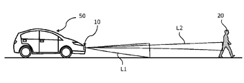
- FIG. 4 is a side view schematically showing a vehicle traveling on the road.
- FIG. 5 is a flowchart showing an example of a distance measuring operation when an oncoming vehicle approaches a vehicle traveling on a road.
- FIG. 6A is a first diagram schematically showing a state in which an oncoming vehicle approaches a vehicle traveling on a road.
- FIG. 6B is a second diagram schematically showing how an oncoming vehicle approaches a vehicle traveling on a road.
- FIG. 6C is a third diagram schematically showing how an oncoming vehicle approaches a vehicle traveling on a road.
- FIG. 6D is a fourth diagram schematically showing a state in which an oncoming vehicle approaches a vehicle traveling on a road.
- FIG. 6E is a fifth diagram schematically showing a state in which an oncoming vehicle approaches a vehicle traveling on a road.
- FIG. 7 is a flowchart showing an example of a distance measuring operation when a preceding vehicle moves away from a vehicle traveling on a road.
- FIG. 8A is a first diagram schematically showing how the preceding vehicle moves away from the vehicle traveling on the road.
- FIG. 8B is a second diagram schematically showing how the preceding vehicle moves away from the vehicle traveling on the road.
- FIG. 8C is a third diagram schematically showing how the preceding vehicle moves away from the vehicle traveling on the road.
- FIG. 8D is a fourth diagram schematically showing how the preceding vehicle moves away from the vehicle traveling on the road.
- FIG. 8E is a fifth diagram schematically showing how the preceding vehicle moves away from the vehicle traveling on the road.
- FIG. 9 is a diagram schematically showing a first example of the light emission timing of the light emitting device, the incident timing of the reflected light on the light receiving device, and the exposure timing.
- FIG. 10 is a diagram schematically showing a second example of the light emission timing of the light emitting device, the incident timing of the reflected light on the light receiving device, and the exposure timing.
- FIG. 11 is a flowchart showing a distance measuring operation in a modified example of the first embodiment.
- FIG. 12 is a flowchart showing a distance measuring operation in a modified example of the second embodiment.
- FIG. 1 is a block diagram showing a schematic configuration of a distance measuring device 10 according to an exemplary embodiment of the present disclosure.
- the distance measuring device 10 in the present embodiment includes a light emitting device 100, a light receiving device 200, and a processing circuit 300.
- the ranging device 10 can be used, for example, as part of a LiDAR system mounted on a vehicle.
- the distance measuring device 10 is configured to irradiate a scene to be measured with light to generate and output distance data.
- the "distance data" in the present disclosure means various data representing the absolute distance of the measurement point from the reference point or the relative depth between the measurement points.
- the distance data may be, for example, distance image data or three-dimensional point cloud data.
- the distance data is not limited to data that directly represents the distance or depth, and may be sensor data itself for calculating the distance or depth, that is, Raw data.
- Raw data may be, for example, luminance data generated based on the intensity of light received by the light receiving device 200.
- the luminance data may be, for example, luminance image data.
- the light emitting device 100 emits a plurality of types of light having different degrees of spread. For example, it is possible to irradiate a light beam or flash light having a relatively large spread toward a scene, or to irradiate a light beam having a small spread toward a specific object in the scene. In other words, the light emitting device 100 can emit a relatively broad first light and a second light that irradiates a range narrower than the irradiation range of the first light.
- the light emitting device 100 may include a first light source that emits a first light and a second light source that emits a second light. Alternatively, the light emitting device 100 may include one light source capable of emitting both the first light and the second light.
- the light receiving device 200 detects the reflected light generated by the light emitted from the light emitting device 100 and outputs a signal corresponding to the intensity of the reflected light.
- the light receiving device 200 includes, for example, one or more image sensors.
- the signal output from the image sensor having a plurality of photodetection cells (hereinafter, also referred to as pixels) arranged in two dimensions includes information on the two-dimensional intensity distribution of the reflected light.
- the light receiving device 200 detects the first reflected light generated by the irradiation of the first light and outputs a first signal corresponding to the intensity of the first reflected light.
- the light receiving device 200 also detects the second reflected light generated by the irradiation of the second light and outputs a second signal according to the intensity of the second reflected light.
- the light receiving device 200 includes a first image sensor that detects the first reflected light and outputs the first signal, and a second image sensor that detects the second reflected light and outputs the second signal. You may be.
- the light receiving device 200 may include one image sensor capable of detecting the first reflected light and the second reflected light and outputting the first signal and the second signal, respectively. When the light receiving device 200 includes one sensor, the configuration of the light receiving device 200 can be simplified.
- the processing circuit 300 controls the light emitting device 100 and the light receiving device 200, and processes the signal output from the light receiving device 200.
- the processing circuit 300 includes one or more processors and one or more recording media.
- the recording medium includes, for example, a memory such as RAM and ROM.
- the recording medium can store a computer program executed by the processor and various data generated in the process.
- the processing circuit 300 may be an aggregate of a plurality of circuits.
- the processing circuit 300 may include a control circuit that controls the light emitting device 100 and the light receiving device 200, and a signal processing circuit that processes a signal output from the light receiving device 200.
- the processing circuit 300 may be built in a housing different from the light emitting device 100 and the light receiving device 200. Further, the processing circuit may be installed at a place away from the light emitting device 100 and the light receiving device 200, and the light emitting device 100 and the light receiving device 200 may be remotely controlled by wireless communication.
- FIG. 2 is a diagram for explaining an outline of the operation of the distance measuring device 10.
- FIG. 2 schematically shows an example of the distance measuring device 10 and an example of a distance image that can be generated by the distance measuring device 10.
- the light emitting device 100 includes a first light source 110 and a second light source 120.
- the first light source 110 is configured to emit flash light L1 as the first light.
- the second light source 120 is configured to emit the light beam L2 as the second light.
- the second light source 120 can change the emission direction of the light beam L2. Thereby, a predetermined area in the space can be scanned by the light beam L2.
- the light receiving device 200 includes an image sensor 210.
- the image sensor 210 in this example is a TOF image sensor capable of measuring a distance by TOF (Time of Flight).
- the image sensor 210 can generate a distance image of a scene to be distance-measured by using a technique of direct TOF or indirect TOF.
- the processing circuit 300 controls the first light source 110, the second light source 120, and the image sensor 210.
- the distance measuring device 10 in the present embodiment acquires distance data of a specific object such as a pedestrian, an automobile, a motorcycle, or a bicycle by using the flash light L1 and the light beam L2.
- the distance measuring device 10 changes the operation mode depending on whether or not the object exists inside the first target range 30T1 included in the range irradiated by the flash light L1.
- the first target range 30T1 is a rectangular range included in the range irradiated by the flash light L1 in the image acquired by the light receiving device 200.
- the first target range 30T1 is not limited to a rectangle, and may be a range such as an ellipse.
- the processing circuit 300 first determines the first target range 30T1 prior to the distance measurement operation.
- the first target range 30T1 can be set, for example, as a range of coordinates in a real three-dimensional space or a range of coordinates in a two-dimensional plane of an image acquired by the light receiving device 200.
- the distance measuring device 10 in this example repeats the operation of irradiating the object with the light beam L2 and acquiring the distance data.
- the operation of irradiating the object with the flash light L1 and acquiring the distance data is repeated.
- the operation of the processing circuit 300 when the object moves outside the first target range 30T1 and when the object moves inside the first target range 30T1 will be described in more detail below.
- the processing circuit 300 When the object exists outside the first target range 30T1, the processing circuit 300 causes the second light source 120 to emit the light beam L2, causes the image sensor 210 to detect the reflected light generated by the light beam L2, and causes the image sensor 210 to detect the reflected light. A second signal corresponding to the amount of detected light of each pixel is output. The processing circuit 300 generates and outputs distance data or luminance data of an object in the scene for each frame based on the second signal.
- the processing circuit 300 calculates the moving direction of the object based on the distance data or the luminance data in a plurality of frames, and causes the second light source 120 to emit the light beam L2 in accordance with the direction. As a result, the processing circuit 300 can track the range 30B of the beam spot of the light beam L2 on the object.
- the plurality of white circles shown in the right side of FIG. 2 represent an example of the range 30B of the beam spot irradiated by the light beam L2.
- the size of the beam spot range 30B changes depending on the angle of view of the scene captured by the image sensor 210, the spread angle of the light beam L2, and the distance of the object. While the object is outside the first target range 30T1, the ranging device 10 may stop emitting the flash light L1 or use the flash light L1 within the first target range 30T1. Distance data may be acquired.
- the processing circuit 300 When the object is inside the first target range 30T1, the processing circuit 300 emits the flash light L1 to the first light source 110, causes the image sensor 210 to detect the reflected light generated by the flash light L1. A first signal corresponding to the amount of detected light of each pixel is output.
- the degree of spread of the flash light L1 is larger than the degree of spread of the light beam L2, while the flash light L1 has a lower energy density as compared with the light beam L2. Therefore, the flash light L1 irradiates the first target range 30T1 which is wide at a relatively short distance.
- the processing circuit 300 repeats an operation of detecting and recording the position of an object existing in the first target range 30T1 based on the first signal.
- this operation may be expressed as "tracking an object internally". Since the flash light L1 can irradiate a relatively wide range, the emission direction of the flash light L1 can be fixed.
- the light emitting device 100 may be configured so that the emission direction of the flash light L1 can be changed.
- the processing circuit 300 outputs, for example, distance data or luminance data of an object at a predetermined frame rate.
- FIG. 3 is a perspective view schematically showing an example of a vehicle 50 in which the distance measuring device 10 is mounted on the front surface.
- the distance measuring device 10 in the vehicle 50 emits the flash light L1 and the light beam L2 toward the front of the vehicle 50.
- the mounting position of the distance measuring device 10 on the vehicle 50 is not limited to the front surface thereof, but may be the upper surface, the side surface, or the rear surface thereof. The mounting position is appropriately determined according to the direction in which the object is measured.
- FIG. 4 is a side view schematically showing an example of the vehicle 50 traveling on the road. Since the degree of spread of the light beam L2 is smaller than the degree of spread of the flash light L1, the irradiation energy density of the light beam L2 is higher than the irradiation energy density of the flash light L1. Therefore, the light beam L2 is suitable for irradiating an object 20 farther than the flash light L1. In the example shown in FIG. 4, the distant object 20 is a pedestrian, but the object 20 can be an object other than a person.
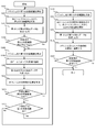
- FIG. 5 is a flowchart showing an example of a distance measuring operation when an object such as an oncoming vehicle approaches a vehicle 50 traveling on a road.
- the processing circuit 300 executes the operations of steps S101 to S114 shown in the flowchart of FIG. 5 during the distance measuring operation.
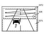
- 6A to 6E are diagrams schematically showing how an oncoming vehicle approaches a vehicle 50 traveling on a road. Time elapses in the order of FIGS. 6A to 6E. 6A to 6E schematically show an example of an image acquired by photographing a scene including an oncoming vehicle from the front of the vehicle 50.
- the lower range is the first target range 30T1 irradiated with the flash light L1, and the upper range is scanned by the light beam L2.
- the second target range is 30T2.
- the second target range 30T2 exists outside the first target range 30T1.
- the processing circuit 300 determines the first target range 30T1 and the second target range 30T2 before the distance measuring operation. The method for determining the first target range 30T1 and the second target range 30T2 will be described later. Hereinafter, the operation of each step shown in FIG. 5 will be described.
- Step S101 The processing circuit 300 causes the light emitting device 100 to irradiate the first target range 30T1 in the scene with the flash light L1.
- the degree of spread of the flash light L1 is larger than the degree of spread of the light beam L2.
- the first target range 30T1 in this example corresponds to a distance relatively closer than the second target range 30T2.
- Step S102 The processing circuit 300 scans the second target range 30T2 in the scene with the light beam L2 by causing the light emitting device 100 to continuously emit the light beam L2 while changing the light emitting direction of the light beam L2.
- the arrow shown in FIG. 6A represents the trajectory of the beam spot range 30B by scanning.
- the second target range 30T2 in this example corresponds to a distance relatively farther than the first target range 30T1.
- the processing circuit 300 causes the light receiving device 200 to detect the first reflected light generated by the irradiation of the flash light L1 and the second reflected light generated by the irradiation of the light beam L2, and causes the light receiving device 200 to detect the first signal and the second reflected light, respectively. Output the signal of.
- the processing circuit 300 generates and outputs first detection data and second detection data indicating the position or distance of the object 20 based on the first signal and the second signal, respectively.
- the processing circuit 300 stores the first detection data and the second detection data in a memory (not shown) in the processing circuit 300.
- the first detection data can be, for example, the distance data within the first target range 30T1 shown in FIG.
- the second detection data can be, for example, distance data within the range 30B of the beam spot shown in FIG.
- first distance data the distance data within the first target range 30T1
- second distance data the distance data within the beam spot range 30B
- the distance data within the first target range 30T1 and the distance data within the beam spot range 30B may be integrated and output. This integration makes it easier to grasp the distance data of the object 20 at a long distance and a short distance.
- Luminance data may be generated and output instead of distance data.
- the detection data within the range 30B of a plurality of beam spots having different irradiation directions may be integrated and output.
- the processing circuit 300 may determine the behavior of the vehicle by driving assistance or automatic driving based on the detection data such as the distance data or the luminance data of the object 20 stored in the memory in time series.
- the processing circuit 300 may display information related to the distance data of the object 20 on a display or an instrument (not shown) in the vehicle 50.
- Step S104 The processing circuit 300 determines whether or not the object 20 to be tracked exists in the second target range 30T2 based on the second detection data.
- the processing circuit 300 may determine what the object 20 is by recognizing a specific object by a known image recognition technique based on distance data or luminance data.
- a particular object is, for example, a car, a motorcycle, a bicycle, or a pedestrian.
- the priority of the objects is determined according to the type of the object, and the object having the highest priority may be the object 20.
- the processing circuit 300 repeatedly executes the operations of steps S101 to S104 to continue searching for the object 20 to be tracked. If the object 20 is within the second target range 30T2 as shown in FIG. 6A, the process proceeds to step S105.
- Step S105 The processing circuit 300 causes the light emitting device 100 to irradiate the first target range 30T1 in the scene with the flash light L1. This operation is the same as the operation in step S101.
- Step S106 The processing circuit 300 determines the emission direction of the light beam L2 based on the information regarding the position of the object 20 included in the second detection data, and causes the light emitting device 100 to irradiate the light beam L2 toward the object 20. ..
- the information about the position of the object 20 can be, for example, a distance or luminance value of the object 20.
- the processing circuit 300 detects the object 20 based on the information regarding the position of the object 20, and interrupts the scanning operation by the light beam L2 as shown in FIG. 6B. After that, the processing circuit 300 tracks the object 20 by the light beam L2 as shown in FIG. 6C in response to the detection of the object 20.
- the processing circuit 300 determines the position of the object 20 in the tracking based on the second detection data.
- the position of the object 20 may be determined using external data acquired from an external sensor such as a camera instead of the second detection data. Alternatively, both the second detection data and the external data may be used.
- Step S107 The processing circuit 300 generates and outputs the first detection data and the second detection data by executing the same operation as in step S103.
- the processing circuit 300 stores the first detection data and the second detection data in a memory (not shown) in the processing circuit 300.
- Step S108 The processing circuit 300 determines whether or not the object 20 has exited the second target range 30T2 based on the information regarding the position of the object 20 included in the second detection data. The determination can be made, for example, based on the value of the distance of the object 20 included in the second detection data. For example, when the value of the distance of the object 20 included in the second detection data is larger than the first reference value or smaller than the second reference value, the object 20 exits the second target range 30T2. It can be determined that the data has been removed.
- the first reference value and the second reference value correspond to the longest and shortest distances in the second target range 30T2 shown in FIG. 6A, respectively.
- the first reference value and the second reference value can be, for example, 200 m and 50 m, respectively.
- the determination may be made based on the brightness value of the object 20 included in the second detection data. For example, when the brightness value of the object 20 included in the second detection data is larger than the third reference value or smaller than the fourth reference value, the object 20 has exited the second target range 30T2. Can be determined.
- the third reference value and the fourth reference value correspond to the luminance values at the shortest and longest distances in the second target range 30T2 shown in FIG. 6A, respectively.
- the irradiation energy density of the light beam L2 is relatively high, and the third reference value can be, for example, 90% of the saturation value of the brightness value in the light receiving device 200.
- the fourth reference value can be, for example, 1% of the saturation value of the luminance value.
- the processing circuit 300 When the object 20 does not come out of the second target range 30T2, the processing circuit 300 repeatedly executes the operations of steps S105 to S108, and continues tracking the object 20 by the light beam L2. When the object 20 comes out of the second target range 30T2, the process proceeds to step S109.
- Step S109 When the object 20 exits the second target range 30T2 as shown in FIG. 6D, the processing circuit 300 determines whether or not the object 20 has entered the first target range 30T1. For example, when the value of the distance of the object 20 included in the second detection data is equal to or less than a predetermined reference value, it may be determined that the object 20 has entered the first target range 30T1.
- the reference value corresponds to the longest distance in the first target range 30T1, and can be, for example, 50 m.
- the value of the distance of the object 20 can be obtained based on the first detection data, it may be determined that the object 20 has entered the first target range 30T1. The determination may be made based on the brightness value of the object 20 included in the second detection data.
- the processing circuit 300 may restart the operation of step S101.
- Step S110 As shown in FIG. 6D, when the object 20 enters the first target range 30T1, the processing circuit 300 sends the first target range 30T1 in the scene to the light emitting device 100 with the flash light L1 as in step S101. Irradiate.
- Step S111 The processing circuit 300 stops tracking the object 20 by the light beam L2. After that, as shown in FIG. 6E, the processing circuit 300 scans the scan range with the light beam as in step S102.
- Step S112 Similar to step S103, the processing circuit 300 generates and outputs the first detection data and the second detection data.
- the processing circuit 300 stores the first detection data and the second detection data in a memory (not shown) in the processing circuit 300.
- Step S113 As shown in FIG. 6E, the processing circuit 300 internally tracks the object 20 by the flash light L1.
- the white arrows shown in FIG. 6E indicate that they are tracking internally.
- This operation corresponds to recording a change in the position of the object 20 in addition to the first detection data. In this respect, the operation is different from the operation of tracking the object 20 by the light beam L2.
- the degree of spread of the flash light L1 is larger than the degree of spread of the light beam L2. Therefore, the irradiation direction of the flash light L1 may be fixed. It is not always necessary to change the irradiation direction of the flash light according to the movement of the object 20.
- the processing circuit 300 determines the position of the object 20 in the tracking based on the first detection data. External data acquired from an external sensor such as a camera may be used instead of the first detection data. Alternatively, both the first detection data and the external data may be used.
- Step S114 The processing circuit 300 determines whether or not the object 20 has come out of the first target range 30T1 based on the first detection data.
- the situation where the object 20 comes out of the first target range 30T1 occurs, for example, when an oncoming vehicle passes by the vehicle 50.
- the processing circuit 300 ends the tracking of the object 20 by the flash light L1 and the light beam L2.
- the processing circuit 300 may restart the operation of step S101.
- the processing circuit 300 repeatedly executes the operations of steps S110 to S114, and continues the internal tracking of the object 20 by the flash light L1.
- the following effects can be obtained by the operations of steps S101 to S114 in the first embodiment. That is, when the object 20 moves to the first target range 30T1 existing near the vehicle 50, the processing circuit 300 does not need to track the object 20 by the light beam L2. Therefore, the processing circuit 300 can efficiently track the distant object 20 moving in the second target range 30T2 by the light beam L2. As a result, data indicating the position of the object 20 in the distance measurement target scene can be efficiently acquired, and the amount of the data can be increased. Further, the necessary data can be acquired in a short time as compared with the configuration in which the entire scene to be distanced is scanned by the light beam L2.
- FIG. 7 is a flowchart of a distance measuring operation according to the second embodiment of the present disclosure when the preceding vehicle moves away from the vehicle 50 traveling on the road.
- the processing circuit 300 executes the operations of steps S201 to S214 shown in the flowchart of FIG. 7 during the distance measuring operation.
- 8A to 8E are diagrams schematically showing how the preceding vehicle moves away from the vehicle 50 traveling on the road. Time elapses in the order of FIGS. 8A to 8E.
- the operation of each step shown in FIG. 7 will be described.
- Step S201 The processing circuit 300 causes the light emitting device 100 to irradiate the first target range 30T1 in the scene with the flash light L1. This operation is the same as the operation of step S101 in the first embodiment.
- Step S202 The processing circuit 300 causes the light emitting device 100 to change the emission direction of the light beam L2 and irradiate the second target range 30T2 in the scene while scanning with the light beam L2. This operation is the same as the operation of step S102 in the first embodiment.
- Step S203 The processing circuit 300 causes the light receiving device 200 to detect the first reflected light generated by the irradiation of the flash light L1 and the second reflected light generated by the irradiation of the light beam L2, and causes the light receiving device 200 to detect the first signal and the second reflected light, respectively. Output the signal of.
- the processing circuit 300 generates and outputs first detection data and second detection data indicating the position of the object 20 based on the first signal and the second signal. This operation is the same as the operation of step S103 in the first embodiment.
- Step S204 The processing circuit 300 determines whether or not the object 20 to be tracked exists in the first target range 30T1 based on the first detection data.
- the method for determining what the object 20 is is as described in step S104 in the first embodiment.
- the processing circuit 300 repeats the operations of steps S201 to S204 to continue the search for the object 20 to be tracked.
- Step S205 When the object 20 exists in the first target range 30T1 as shown in FIG. 8A, the processing circuit 300 executes the same operation as in step S201.
- Step S206 The processing circuit 300 executes the same operation as in step S202.
- Step S207 The processing circuit 300 executes the same operation as in step S203.
- Step S208 As shown in FIG. 8B, the processing circuit 300 internally tracks the object 20 by the flash light L1. This operation is the same as the operation of step S113 in the first embodiment.
- Step S209 The processing circuit 300 determines whether or not the object 20 has exited the first target range 30T1 based on the information regarding the position of the object 20 included in the first detection data. For example, when the distance value of the object 20 included in the first detection data is equal to or greater than a predetermined reference value, it may be determined that the object 20 has exited the first target range 30T1.
- the reference value corresponds to the longest distance value in the first target range 30T1.
- the reference value of the distance value can be, for example, 50 m.
- the value of the distance of the object 20 cannot be obtained based on the first detection data, it may be determined that the object 20 has exited the first target range 30T1.
- the determination may be made based on the brightness value of the object 20 included in the first detection data. For example, when the brightness value of the object 20 is equal to or less than a predetermined reference value, it may be determined that the object 20 has come out of the first target range 30T1. This reference value corresponds to the brightness value at the longest distance value in the first target range 30T1.
- the irradiation energy density of the flash light L1 is relatively low, and the reference value of the brightness value can be, for example, 10% of the saturation value of the brightness value.
- Step S210 When the object 20 exits the first target range 30T1 as shown in FIG. 8C, the processing circuit 300 determines whether or not the object 20 has entered the second target range 30T2. The determination can be made, for example, based on the value of the distance of the object 20 included in the second detection data. For example, when the value of the distance of the object 20 included in the second detection data is larger than the first reference value or smaller than the second reference value, the object 20 exits the second target range 30T2. It can be determined that the data has been removed.
- the first reference value and the second reference value correspond to the longest and shortest distances in the second target range 30T2 shown in FIG. 8A, respectively.
- the first reference value and the second reference value can be, for example, 200 m and 50 m, respectively.
- the determination may be made based on the brightness value of the object 20 included in the second detection data. For example, when the brightness value of the object 20 included in the second detection data is larger than the third reference value or smaller than the fourth reference value, the object 20 has exited the second target range 30T2. Can be determined.
- the third reference value and the fourth reference value correspond to the luminance values at the shortest and longest distances in the second target range 30T2 shown in FIG. 8A, respectively.
- the third reference value and the fourth reference value can be, for example, 90% and 1% of the saturation value of the luminance value, respectively.
- the processing circuit 300 ends the tracking of the object 20 by the flash light L1 and the light beam L2.
- a situation in which the object 20 exits the first target range 30T1 but does not enter the second target range 30T2 occurs, for example, when the object 20 crosses a road.
- the processing circuit 300 may restart the operation of step S201.
- Step S211 The processing circuit 300 executes the same operation as in step S201.
- Step S212 The processing circuit 300 determines the emission direction of the light beam L2 based on the information regarding the position of the object 20 included in the second detection data, and causes the light emitting device 100 to irradiate the light beam L2 toward the object 20. .. In other words, the processing circuit 300 interrupts the scanning operation by the light beam L2 as shown in FIG. 8C, and tracks the object 20 by the light beam L2 as shown in FIG. 8D.
- Step S213 The processing circuit 300 executes the same operation as in step S203.
- Step S214 The processing circuit 300 determines whether or not the object 20 has come out of the second target range 30T2 based on the second detection data. When the object 20 comes out of the second target range 30T2, the processing circuit 300 ends the tracking of the object 20 by the flash light L1 and the light beam L2. The processing circuit 300 may restart the operation of step S201. When the object 20 does not go out of the second target range 30T2, the processing circuit 300 repeatedly executes the operations of steps S211 to S214, and continues tracking the object 20 by the light beam L2.
- steps S201 to S214 in the second embodiment By the operation of steps S201 to S214 in the second embodiment, the same effect as that of the first embodiment can be obtained.
- both an oncoming vehicle approaching the vehicle 50 as in the first embodiment and a preceding vehicle moving away from the vehicle 50 as in the second embodiment can exist at the same time.
- one distance measuring device 10 mounted on the vehicle 50 separates the first operation of measuring the distance of the oncoming vehicle approaching the vehicle 50 and the second operation of measuring the distance of the preceding vehicle away from the vehicle 50. You may execute it with.
- the one distance measuring device 10 may alternately execute the first operation and the second operation for each frame, execute the first operation for a predetermined number of frames, and then execute the second operation for a predetermined number of frames. You may.
- the first operation and the second operation may be interchanged.
- the vehicle 50 is equipped with two ranging devices 10, one of the two ranging devices 10 measures the oncoming vehicle approaching the vehicle 50, and the other measures the distance of the preceding vehicle moving away from the vehicle 50. You may.
- the first target range 30T1 may be determined based on the distance value.
- the first target range 30T1 may have a distance value within a range of 20 m or more and 50 m or less from the distance measuring device 10.
- the first target range 30T1 may be determined based on the brightness value of the reflected light from the object 20.
- the reason is that the intensity of the illumination light is not uniform within the irradiation range, especially in the case of flash light. Another reason is that even if the objects 20 are at the same distance, they are detected by the image sensor 210 depending on the reflectance or scattering property of the object 20 or the direction of the normal on the surface of the object 20.
- the brightness value of the reflected light changes.
- An example of the brightness value of the reflected light is the brightness value of the reflected light from the object 20 generated by the irradiation of the flash light L1.
- the irradiation energy density of the flash light L1 is relatively low, and the first target range 30T1 may have a brightness value of the reflected light in a range of 10% or more of the saturation value of the brightness value.
- the brightness value of the reflected light is the brightness value of the reflected light from the object 20 generated by the irradiation of the light beam L2.
- the irradiation energy density of the light beam L2 is relatively high, and the first target range 30T1 may have a brightness value of the reflected light in a range of 90% or more of the saturation value of the brightness value.
- the first target range 30T1 may be determined based on at least one selected from the group consisting of the first detection data, the second detection data, and the external data.
- the first reference value and the second reference value of the above-mentioned distance value are determined from the distance data obtained from at least one selected from the group consisting of the first detection data, the second detection data, and the external data. You may. Further, from the luminance data obtained from at least one selected from the group consisting of the first detection data, the second detection data, and the external data, the third reference value and the second reference value of the above-mentioned luminance values are used. You may decide.
- the first target range 30T1 may be determined based on the reliability of the position of the object 20.
- the reliability of the position of the object 20 is determined based on, for example, at least one selected from a group consisting of a plurality of first detection data, a plurality of second detection data, and a plurality of external data. It can be defined by the dispersion of the positions of the objects 20.
- the processing circuit 300 generates and outputs the first detection data or the second detection data a plurality of times, or acquires the external data from an external device a plurality of times to calculate the reliability of the position of the object 20. .. It is considered that the reliability of the position of the object 20 is low in the range where the variance of the position of the object 20 is larger than the predetermined reference value. Therefore, the range in which the variance is equal to or greater than a predetermined reference value may be set as the first target range 30T1.
- the first target range 30T1 may be determined based on at least one selected from the group consisting of the luminance value, the distance value, and the external data, or may be appropriately changed.
- the second target range 30T2 may be determined by the same method as the first target range 30T1.
- the second target range 30T2 can be, for example, a distance value within a range of 50 m or more and 200 m or less from the distance measuring device 10.
- the second target range 30T2 may be, for example, a range in which the brightness value of the reflected light generated by the irradiation of the light beam L2 is 1% or more and 90% or less of the saturation value of the brightness value.
- the second target range 30T2 is, for example, a range not included in the first target range 30T1 and can generate distance data or luminance data by the reflected light generated by the irradiation of the light beam L2. Range can be.
- FIG. 9 shows the emission timing of the flash light L1 and the light beam L2 emitted from the light emitting device 100 in one frame, the incident timing of the first reflected light and the second reflected light on the light receiving device 200, and the light receiving device. It is a figure which shows typically the 1st example with the exposure timing of 200. In the example shown in FIG. 9, the operation of the indirect TOF is described.
- the exposure period for light detection by the image sensor 210 is set to three times the light emission period ⁇ t of the flash light L1 and the light beam L2.
- the amount of light detected by the light receiving device 200 in the first to third periods obtained by dividing the exposure period into three equal parts is A0 to A2, respectively.
- ⁇ be the difference between the timing of the start of light emission and the timing of the start of exposure.
- Processing circuit 300 utilizes the indirect TOF technology, the detected light A2, and the timing difference t 0 from the detected light intensity A0, calculates the distance to the object 20.
- ⁇ be the round-trip time until the flash light L1 and the light beam L2 are emitted, reflected by the object 20, and returned as the first reflected light and the second reflected light, respectively, and the speed of light in the air is c.
- the distance to the object 20 is c ⁇ / 2.
- A2 in this equation corresponds to the amount of detected noise light contained in A0 and A1.
- A0 in this equation corresponds to the amount of detected noise light contained in A1 and A2. Depending on the application, the amount of detected noise light may not be considered.
- the processing circuit 300 causes the light emitting device 100 to simultaneously emit the flash light L1 and the light beam L2, and the image sensor 210 detects the first reflected light and the second reflected light within the same exposure period. Let me. By this operation, the number of exposures per frame can be increased. As a result, the S / N of the signal detected by the image sensor 210 can be improved, and high-precision distance measurement becomes possible.
- the timing at which the first reflected light is incident on the light receiving device 200 and the second The time difference from the timing at which the reflected light enters the light receiving device 200 can be large.
- the first reflected light and the second reflected light can be detected within a common exposure period by temporally shifting the light emission timing of the flash light L1 and the light emission timing of the light beam L2.
- FIG. 10 shows the emission timing of the flash light L1 and the light beam L2 emitted from the light emitting device 100 in one frame, the incident timing of the first reflected light and the second reflected light on the light receiving device 200, and the light receiving device. It is a figure which shows typically the 2nd example with the exposure timing of 200.
- the light emitting operation of the flash light L1 and the exposure operation of the first reflected light are independent of the light emitting operation of the light beam L2 and the exposure operation of the second reflected light.
- the exposure period for detecting the first reflected light and the exposure period for detecting the second reflected light can be set independently. Therefore, even if the distance at which the object 20 is measured by the flash light L1 and the distance at which the object 20 is measured by the light beam L2 are significantly different, the object 20 can be measured without any problem.
- FIG. 11 is a flowchart of the distance measuring operation in the modified example of the first embodiment.
- the difference between the modified example of the first embodiment and the first embodiment is the operation of steps S121 to S123.
- Step S121 The processing circuit 300 predicts the future position of the object 20 based on the information regarding the position of the object 20 included in the second detection data.
- the "future" may be the next frame or a plurality of frames ahead.
- the future position of the object 20 can be predicted, for example, as follows.
- the movement vector of the object 20 in the three-dimensional space may be calculated from the distance data to the current frame acquired by the repetitive motion, and the future position of the object 20 may be predicted based on the movement vector. ..
- the optical flow of the object 20 may be calculated from the luminance data up to the current frame acquired by the repetitive operation, and the future position of the object 20 may be predicted based on the optical flow.
- Step S122 The processing circuit 300 determines whether or not the predicted position of the object 20 exists outside the second target range 30T2. When the predicted position of the object 20 does not exist outside the second target range 30T2, the processing circuit 300 repeatedly executes the operations of steps S105 to S122, and continues tracking the object 20 by the light beam L2.
- Step S123 When the predicted position of the object 20 exists outside the second target range 30T2, the processing circuit 300 determines whether or not the predicted position exists within the first target range 30T1. The determination criteria are as described in step S109 of the first embodiment. When the object 20 does not exist within the first target range 30T1, the processing circuit 300 ends the tracking of the object 20 by the flash light L1 and the light beam L2. The processing circuit 300 may restart the operation of step S101.
- the following effects can be obtained by the operations of steps S121 to S123 in the modified example of the first embodiment. That is, when the object 20 moves from the second target range 30T2 to the first target range 30T1, it is possible to reduce the overhead time of simultaneously irradiating the object 20 with the flash light L1 and the light beam L2. As a result, data indicating the position of the object 20 in the distance measurement target scene can be acquired more efficiently, and the amount of the data can be further increased.
- FIG. 12 is a flowchart of the distance measuring operation in the modified example of the second embodiment.
- the difference between the modified example of the second embodiment and the second embodiment is the operation of steps S221 to S223.
- Step S221 The processing circuit 300 predicts the position of the object 20 in the future based on the information of the object 20 included in the first detection data.
- the position of the object 20 is predicted as described in step S121 in the modified example of the first embodiment.
- Step S222 The processing circuit 300 determines whether or not the predicted position of the object 20 exists outside the first target range 30T1. When the predicted position of the object 20 does not exist outside the first target range 30T1, the processing circuit 300 repeatedly executes the operations of steps S205 to S222 to perform internal tracking of the object 20 by the flash light L1. continue.
- Step S223 When the predicted position of the object 20 is outside the first target range 30T1, the processing circuit 300 determines whether or not the predicted position is within the second target range 30T2. The determination criteria are as described in step S210 in the second embodiment. When the predicted position of the object 20 does not exist in the second target range 30T2, the processing circuit 300 ends the tracking of the object 20 by the flash light L1 and the light beam L2. The processing circuit 300 may restart the operation of step S201.
- the distance measuring devices according to the first and second embodiments of the present disclosure are described below for each item.
- the distance measuring device may emit a first light and a second light having a smaller degree of spread than the first light, and may change the emission direction of the second light. It includes a possible light emitting device, a light receiving device, and a processing circuit that controls the light emitting device and the light receiving device and processes a signal output from the light receiving device.
- the processing circuit generates first distance data based on the first signal obtained by the light receiving device detecting the first reflected light generated by the first light, and the light receiving device generates the first distance data.
- a second distance data is generated based on the second signal obtained by detecting the second reflected light generated by the second light, and the range in which the object is irradiated by the first light.
- this distance measuring device it is possible to efficiently acquire the distance data of an object entering from the outside to the inside of the first target range in the distance measuring target scene.
- the distance measuring device is the distance measuring device according to the first item, in which the processing circuit performs the first distance data after the object enters the inside of the first target range. In addition, the change in the position of the object is recorded.
- this ranging device it is possible to internally track an object that has entered the inside of the first target range.
- the distance measuring device is a second target range in which the processing circuit is provided to the light emitting device outside the first target range in the distance measuring device according to the first or second item. Is scanned by the second light, the object is detected based on the second signal or the second distance data obtained by the scan, and the object is detected. The light emitting device is made to start tracking the object by the second light. With this ranging device, it is possible to track an object in the second target range.
- the ranging device may emit a first light and a second light having a smaller degree of spread than the first light, and may change the emission direction of the second light. It includes a possible light emitting device, a light receiving device, and a processing circuit that controls the light emitting device and the light receiving device and processes a signal output from the light receiving device.
- the processing circuit generates first distance data based on the first signal obtained by the light receiving device detecting the first reflected light generated by the first light, and the light receiving device generates the first distance data.
- Second distance data is generated based on the second signal obtained by detecting the second reflected light generated by the second light, and the object is included in the range irradiated by the first light.
- the change in the position of the target is recorded in addition to the first distance data, and the target moves from the inside to the outside of the first target range. Then, the light emitting device is made to start tracking the object by the second light.
- this distance measuring device it is possible to efficiently acquire distance data of an object moving from the inside to the outside of the first target range in the distance measuring target scene.
- the distance measuring device is the distance measuring device according to any one of the first to fourth items, and when the object is outside the first target range, the processing circuit is used. Distance measurement by the first light is performed.
- the distance measuring device is the distance measuring device according to any one of the first to fifth items, in which the processing circuit is such that the object is outside or inside the first target range. From the group consisting of the strength of the first signal, the strength of the second signal, the first distance data, the second distance data, and the external data input from the external sensor. Determined based on at least one selected.
- the position of the object can be determined by at least one selected from the group consisting of the brightness value, the distance value, and the external data.
- the distance measuring device is the distance measuring device according to any one of the first to sixth items, in which the processing circuit moves from the outside to the inside of the first target range of the object. , And the movement from the inside to the outside, the strength of the first signal, the strength of the second signal, the first distance data, the second distance data, and the external data input from the external sensor. Predict based on at least one selected from the group consisting of.
- the above movement of the object can be determined by at least one selected from the group consisting of the luminance value, the distance value, and the external data.
- the distance measuring device is an image sensor in which the light receiving device has a plurality of pixels arranged two-dimensionally in the distance measuring device according to any one of the first to seventh items.
- this ranging device it is possible to acquire ranging image data or luminance image data of an object.
- the distance measuring device is the distance measuring device according to the first item, wherein the processing circuit has the strength of the first signal, the strength of the second signal, the first distance data, and the like.
- the first target range is changed based on at least one selected from the group consisting of the second distance data and the external data input from the external sensor.
- the first target range is determined based on at least one selected from the distance value, the brightness value, and the external data.
- the distance measuring device is the distance measuring device according to the eighth item, wherein the processing circuit has the strength of the first signal, the strength of the second signal, the first distance data, and the like.
- the position of the object is detected based on at least one selected from the group consisting of the second distance data and the external data, and the reliability of the position of the object defined by the dispersion of the position of the object.
- the degree is calculated, and the first target range is determined based on the reliability of the position of the object.
- the first target range is determined based on the reliability of the position of the object.
- the distance measuring device is the distance measuring device according to any one of the first to tenth items, in which the processing circuit integrates the first distance data and the second distance data. Output.
- This distance measuring device makes it easy to grasp the distance data of an object at a long distance and a short distance.
- the distance measuring device is the distance measuring device according to any one of the first to eleventh items, wherein the first light is flash light and the second light is an optical beam.
- this distance measuring device it is possible to efficiently acquire distance data of an object by flash light and light beam having greatly different irradiation ranges.
- the program according to the thirteenth item can emit the first light and the second light having a smaller degree of spread than the first light, and can change the emission direction of the second light.
- a program used in a distance measuring device including a light emitting device, a light receiving device, a processing circuit that controls the light emitting device and the light receiving device, and processes a signal output from the light receiving device, and is a processing circuit.
- the light receiving device generates the first distance data based on the first signal obtained by detecting the first reflected light generated by the first light, and the light receiving device is said to be said.
- the second distance data is generated based on the second signal obtained by detecting the second reflected light generated by the second light, and the object is irradiated with the first light.
- the light emitting device When the object is outside the first target range included in the range, the light emitting device is made to track the object by the second light, and the object is moved from the outside to the inside of the first target range. Upon entering, the light emitting device is made to stop the tracking by the second light.
- This program makes it possible to efficiently acquire the distance data of an object entering from the outside to the inside of the first target range in the distance measurement target scene.
- the program according to the fourteenth item can emit the first light and the second light having a smaller degree of spread than the first light, and can change the emission direction of the second light.
- a program used in a distance measuring device including a light emitting device, a light receiving device, a processing circuit that controls the light emitting device and the light receiving device, and processes a signal output from the light receiving device, and is a processing circuit.
- the light receiving device generates the first distance data based on the first signal obtained by detecting the first reflected light generated by the first light
- the light receiving device generates the first distance data.
- To generate the second distance data based on the second signal obtained by detecting the second reflected light generated by the second light, and to the range where the object is irradiated by the first light.
- the change in the position of the object is recorded in addition to the first distance data, and the object is from the inside of the first target range.
- it moves to the outside, it causes the light emitting device to start tracking the object by the second light.
- This program makes it possible to efficiently acquire the distance data of an object moving from the inside to the outside of the first target range in the distance measurement target scene.
- the ranging device in the present disclosure can be used, for example, for applications of a LiDAR system mounted on a vehicle such as an automobile, an AGV (automated guided vehicle), and an air vehicle such as a UAV (unmanned aerial vehicle).
- a LiDAR system mounted on a vehicle such as an automobile, an AGV (automated guided vehicle), and an air vehicle such as a UAV (unmanned aerial vehicle).
- the ranging device in the present disclosure can also be applied to, for example, a monitoring system attached to a building.
Abstract
Un dispositif de mesure de distance selon la présente invention comprend : un dispositif d'émission de lumière qui est capable d'émettre une première lumière et une seconde lumière qui se propage moins que la première lumière et de changer la direction d'émission de la seconde lumière ; un dispositif de réception de lumière ; et un circuit de traitement qui commande le dispositif d'émission de lumière et le dispositif de réception de lumière et traite des signaux délivrés en sortie du dispositif de réception de lumière, le dispositif de réception de lumière détectant une lumière réfléchie produite par la première lumière et la seconde lumière et générant des premières données de distance et des secondes données de distance, respectivement, et le circuit de traitement amenant le dispositif d'émission de lumière à poursuivre un objet avec la seconde lumière lorsque l'objet est à l'extérieur d'une première plage cible comprise dans la plage irradiée avec la première lumière, et amenant le dispositif d'émission de lumière à arrêter la poursuite avec la seconde lumière lorsque l'objet entre dans la première plage cible depuis l'extérieur de la première plage cible.
Priority Applications (3)
| Application Number | Priority Date | Filing Date | Title |
|---|---|---|---|
| EP20924762.6A EP4119975A4 (fr) | 2020-03-11 | 2020-12-28 | Dispositif de mesure de distance |
| JP2022505787A JPWO2021181841A1 (fr) | 2020-03-11 | 2020-12-28 | |
| US17/820,267 US20220404499A1 (en) | 2020-03-11 | 2022-08-17 | Distance measurement apparatus |
Applications Claiming Priority (2)
| Application Number | Priority Date | Filing Date | Title |
|---|---|---|---|
| JP2020041891 | 2020-03-11 | ||
| JP2020-041891 | 2020-03-11 |
Related Child Applications (1)
| Application Number | Title | Priority Date | Filing Date |
|---|---|---|---|
| US17/820,267 Continuation US20220404499A1 (en) | 2020-03-11 | 2022-08-17 | Distance measurement apparatus |
Publications (1)
| Publication Number | Publication Date |
|---|---|
| WO2021181841A1 true WO2021181841A1 (fr) | 2021-09-16 |
Family
ID=77671557
Family Applications (1)
| Application Number | Title | Priority Date | Filing Date |
|---|---|---|---|
| PCT/JP2020/049225 WO2021181841A1 (fr) | 2020-03-11 | 2020-12-28 | Dispositif de mesure de distance |
Country Status (4)
| Country | Link |
|---|---|
| US (1) | US20220404499A1 (fr) |
| EP (1) | EP4119975A4 (fr) |
| JP (1) | JPWO2021181841A1 (fr) |
| WO (1) | WO2021181841A1 (fr) |
Citations (8)
| Publication number | Priority date | Publication date | Assignee | Title |
|---|---|---|---|---|
| JPH03110389U (fr) * | 1990-02-28 | 1991-11-12 | ||
| JPH1172563A (ja) * | 1997-08-28 | 1999-03-16 | Nissan Motor Co Ltd | 前方認識装置 |
| JPH1172562A (ja) * | 1997-08-28 | 1999-03-16 | Nissan Motor Co Ltd | 車間距離警報装置 |
| JP2008509413A (ja) * | 2004-08-07 | 2008-03-27 | ローベルト ボツシユ ゲゼルシヤフト ミツト ベシユレンクテル ハフツング | センサシステムの作動方法および作動装置 |
| JP2017173298A (ja) | 2016-03-16 | 2017-09-28 | 株式会社リコー | 物体検出装置及び移動体装置 |
| US20180217258A1 (en) | 2017-01-31 | 2018-08-02 | Panasonic Intellectual Property Management Co., Ltd. | Imaging system |
| US10061020B2 (en) | 2015-09-20 | 2018-08-28 | Qualcomm Incorporated | Light detection and ranging (LIDAR) system with dual beam steering |
| JP2018185342A (ja) | 2013-11-20 | 2018-11-22 | パナソニックIpマネジメント株式会社 | 測距撮像システム |
Family Cites Families (1)
| Publication number | Priority date | Publication date | Assignee | Title |
|---|---|---|---|---|
| EP1969312B1 (fr) * | 2005-12-08 | 2017-03-29 | Advanced Scientific Concepts INC. | Telemesure, poursuite et designation par laser utilisant des plans focaux en 3d |
-
2020
- 2020-12-28 JP JP2022505787A patent/JPWO2021181841A1/ja active Pending
- 2020-12-28 WO PCT/JP2020/049225 patent/WO2021181841A1/fr unknown
- 2020-12-28 EP EP20924762.6A patent/EP4119975A4/fr active Pending
-
2022
- 2022-08-17 US US17/820,267 patent/US20220404499A1/en active Pending
Patent Citations (8)
| Publication number | Priority date | Publication date | Assignee | Title |
|---|---|---|---|---|
| JPH03110389U (fr) * | 1990-02-28 | 1991-11-12 | ||
| JPH1172563A (ja) * | 1997-08-28 | 1999-03-16 | Nissan Motor Co Ltd | 前方認識装置 |
| JPH1172562A (ja) * | 1997-08-28 | 1999-03-16 | Nissan Motor Co Ltd | 車間距離警報装置 |
| JP2008509413A (ja) * | 2004-08-07 | 2008-03-27 | ローベルト ボツシユ ゲゼルシヤフト ミツト ベシユレンクテル ハフツング | センサシステムの作動方法および作動装置 |
| JP2018185342A (ja) | 2013-11-20 | 2018-11-22 | パナソニックIpマネジメント株式会社 | 測距撮像システム |
| US10061020B2 (en) | 2015-09-20 | 2018-08-28 | Qualcomm Incorporated | Light detection and ranging (LIDAR) system with dual beam steering |
| JP2017173298A (ja) | 2016-03-16 | 2017-09-28 | 株式会社リコー | 物体検出装置及び移動体装置 |
| US20180217258A1 (en) | 2017-01-31 | 2018-08-02 | Panasonic Intellectual Property Management Co., Ltd. | Imaging system |
Non-Patent Citations (1)
| Title |
|---|
| See also references of EP4119975A4 |
Also Published As
| Publication number | Publication date |
|---|---|
| EP4119975A1 (fr) | 2023-01-18 |
| JPWO2021181841A1 (fr) | 2021-09-16 |
| EP4119975A4 (fr) | 2023-08-09 |
| US20220404499A1 (en) | 2022-12-22 |
Similar Documents
| Publication | Publication Date | Title |
|---|---|---|
| US11346951B2 (en) | Object detection system | |
| US11662433B2 (en) | Distance measuring apparatus, recognizing apparatus, and distance measuring method | |
| EP2910971B1 (fr) | Appareil de reconnaissance d'objet et procédé de reconnaissance d'objet | |
| AU2019369212B2 (en) | Time-of-flight sensor with structured light illuminator | |
| JP6528447B2 (ja) | 視差演算システム及び距離測定装置 | |
| JP5238868B2 (ja) | 車両の物体距離認識システム及び作動方法 | |
| US10222459B2 (en) | Method for controlling a micro-mirror scanner, and micro-mirror scanner | |
| JP2020003236A (ja) | 測距装置、移動体、測距方法、測距システム | |
| KR101980697B1 (ko) | 객체 정보 획득 장치 및 방법 | |
| AU2019315355B2 (en) | Hybrid time-of-flight and imager module | |
| KR102059244B1 (ko) | 라이다 장치 | |
| JP2019078716A (ja) | 距離計測装置、距離計測システム、撮像装置、移動体、距離計測装置の制御方法およびプログラム | |
| JPWO2015182135A1 (ja) | センシングシステム及び運転支援システム | |
| WO2021181841A1 (fr) | Dispositif de mesure de distance | |
| US20220214434A1 (en) | Gating camera | |
| WO2021065138A1 (fr) | Dispositif de mesure de distances et procédé de commande | |
| WO2021199888A1 (fr) | Procédé et dispositif pour commander un dispositif de mesure de distance | |
| KR102636740B1 (ko) | 차량 및 그 제어방법 | |
| JP2022012559A (ja) | 電磁波検出装置および測距装置 | |
| CN116034051A (zh) | 用于至少一个对象的对象追踪方法、用于执行这种方法的控制装置、具有这种控制装置的对象追踪装置和具有这种对象追踪装置的机动车 |
Legal Events
| Date | Code | Title | Description |
|---|---|---|---|
| 121 | Ep: the epo has been informed by wipo that ep was designated in this application |
Ref document number: 20924762 Country of ref document: EP Kind code of ref document: A1 |
|
| ENP | Entry into the national phase |
Ref document number: 2022505787 Country of ref document: JP Kind code of ref document: A |
|
| NENP | Non-entry into the national phase |
Ref country code: DE |
|
| ENP | Entry into the national phase |
Ref document number: 2020924762 Country of ref document: EP Effective date: 20221011 |