WO2021181841A1 - Distance measuring device - Google Patents
Distance measuring device Download PDFInfo
- Publication number
- WO2021181841A1 WO2021181841A1 PCT/JP2020/049225 JP2020049225W WO2021181841A1 WO 2021181841 A1 WO2021181841 A1 WO 2021181841A1 JP 2020049225 W JP2020049225 W JP 2020049225W WO 2021181841 A1 WO2021181841 A1 WO 2021181841A1
- Authority
- WO
- WIPO (PCT)
- Prior art keywords
- light
- target range
- processing circuit
- distance
- receiving device
- Prior art date
Links
Images


Classifications
-
- G—PHYSICS
- G01—MEASURING; TESTING
- G01S—RADIO DIRECTION-FINDING; RADIO NAVIGATION; DETERMINING DISTANCE OR VELOCITY BY USE OF RADIO WAVES; LOCATING OR PRESENCE-DETECTING BY USE OF THE REFLECTION OR RERADIATION OF RADIO WAVES; ANALOGOUS ARRANGEMENTS USING OTHER WAVES
- G01S17/00—Systems using the reflection or reradiation of electromagnetic waves other than radio waves, e.g. lidar systems
- G01S17/66—Tracking systems using electromagnetic waves other than radio waves
-
- G—PHYSICS
- G01—MEASURING; TESTING
- G01S—RADIO DIRECTION-FINDING; RADIO NAVIGATION; DETERMINING DISTANCE OR VELOCITY BY USE OF RADIO WAVES; LOCATING OR PRESENCE-DETECTING BY USE OF THE REFLECTION OR RERADIATION OF RADIO WAVES; ANALOGOUS ARRANGEMENTS USING OTHER WAVES
- G01S17/00—Systems using the reflection or reradiation of electromagnetic waves other than radio waves, e.g. lidar systems
- G01S17/02—Systems using the reflection of electromagnetic waves other than radio waves
- G01S17/06—Systems determining position data of a target
- G01S17/08—Systems determining position data of a target for measuring distance only
- G01S17/32—Systems determining position data of a target for measuring distance only using transmission of continuous waves, whether amplitude-, frequency-, or phase-modulated, or unmodulated
-
- G—PHYSICS
- G01—MEASURING; TESTING
- G01S—RADIO DIRECTION-FINDING; RADIO NAVIGATION; DETERMINING DISTANCE OR VELOCITY BY USE OF RADIO WAVES; LOCATING OR PRESENCE-DETECTING BY USE OF THE REFLECTION OR RERADIATION OF RADIO WAVES; ANALOGOUS ARRANGEMENTS USING OTHER WAVES
- G01S17/00—Systems using the reflection or reradiation of electromagnetic waves other than radio waves, e.g. lidar systems
- G01S17/02—Systems using the reflection of electromagnetic waves other than radio waves
- G01S17/06—Systems determining position data of a target
- G01S17/42—Simultaneous measurement of distance and other co-ordinates
-
- G—PHYSICS
- G01—MEASURING; TESTING
- G01S—RADIO DIRECTION-FINDING; RADIO NAVIGATION; DETERMINING DISTANCE OR VELOCITY BY USE OF RADIO WAVES; LOCATING OR PRESENCE-DETECTING BY USE OF THE REFLECTION OR RERADIATION OF RADIO WAVES; ANALOGOUS ARRANGEMENTS USING OTHER WAVES
- G01S17/00—Systems using the reflection or reradiation of electromagnetic waves other than radio waves, e.g. lidar systems
- G01S17/88—Lidar systems specially adapted for specific applications
- G01S17/93—Lidar systems specially adapted for specific applications for anti-collision purposes
- G01S17/931—Lidar systems specially adapted for specific applications for anti-collision purposes of land vehicles
-
- G—PHYSICS
- G01—MEASURING; TESTING
- G01S—RADIO DIRECTION-FINDING; RADIO NAVIGATION; DETERMINING DISTANCE OR VELOCITY BY USE OF RADIO WAVES; LOCATING OR PRESENCE-DETECTING BY USE OF THE REFLECTION OR RERADIATION OF RADIO WAVES; ANALOGOUS ARRANGEMENTS USING OTHER WAVES
- G01S7/00—Details of systems according to groups G01S13/00, G01S15/00, G01S17/00
- G01S7/48—Details of systems according to groups G01S13/00, G01S15/00, G01S17/00 of systems according to group G01S17/00
- G01S7/4802—Details of systems according to groups G01S13/00, G01S15/00, G01S17/00 of systems according to group G01S17/00 using analysis of echo signal for target characterisation; Target signature; Target cross-section
-
- G—PHYSICS
- G01—MEASURING; TESTING
- G01S—RADIO DIRECTION-FINDING; RADIO NAVIGATION; DETERMINING DISTANCE OR VELOCITY BY USE OF RADIO WAVES; LOCATING OR PRESENCE-DETECTING BY USE OF THE REFLECTION OR RERADIATION OF RADIO WAVES; ANALOGOUS ARRANGEMENTS USING OTHER WAVES
- G01S7/00—Details of systems according to groups G01S13/00, G01S15/00, G01S17/00
- G01S7/48—Details of systems according to groups G01S13/00, G01S15/00, G01S17/00 of systems according to group G01S17/00
- G01S7/481—Constructional features, e.g. arrangements of optical elements
- G01S7/4817—Constructional features, e.g. arrangements of optical elements relating to scanning
-
- G—PHYSICS
- G01—MEASURING; TESTING
- G01S—RADIO DIRECTION-FINDING; RADIO NAVIGATION; DETERMINING DISTANCE OR VELOCITY BY USE OF RADIO WAVES; LOCATING OR PRESENCE-DETECTING BY USE OF THE REFLECTION OR RERADIATION OF RADIO WAVES; ANALOGOUS ARRANGEMENTS USING OTHER WAVES
- G01S7/00—Details of systems according to groups G01S13/00, G01S15/00, G01S17/00
- G01S7/48—Details of systems according to groups G01S13/00, G01S15/00, G01S17/00 of systems according to group G01S17/00
- G01S7/491—Details of non-pulse systems
- G01S7/4911—Transmitters
Definitions
- This disclosure relates to a distance measuring device.
- Patent Document 1 describes a light projecting system including a light source, a light receiving system including a photodetector that receives light projected from the light source system and reflected by an object, and a signal to which an output signal of the photodetector is input.
- An object detection device including a processing system and a control system is disclosed. The control system sets at least one region within the light projection range of the light projection system as a region of interest, and when the light projection condition of the light projection system or the processing condition of the signal processing system is projected onto the region of interest and the region of interest. It is controlled so as to be different from when the light is projected to an area other than the above.
- Patent Document 2 discloses a LiDAR (Light Detection and Ringing) device.
- the LiDAR device includes a first beam scanner, a second beam scanner, and a controller.
- the first beam scanner scans the first region with the first laser beam of the first scan pattern.
- the second beam scanner scans a second region narrower than the first region with the second laser beam of the second scan pattern.
- the controller drives the first beam scanner to scan the first region and acquire the data of the reflected light from the first laser beam.
- One or more objects are determined from the data, and the objects are monitored by driving the second beam scanner to irradiate the inside of the second region.
- Patent Document 3 discloses a ranging imaging device. Based on the signal output from the image sensor that detects passive light, this range-finding imaging device identifies a subject that requires range-finding from the entire imaging target area. This distance measuring image pickup device measures the distance to the subject by irradiating the subject with a laser beam and detecting the reflected light.
- Patent Document 4 discloses a device that scans a space with an optical beam and receives reflected light from an object with an image sensor to acquire distance information.
- the present disclosure provides a technique that enables efficient acquisition of distance data of an object in a distance measurement target scene.
- the ranging device emits a first light and a second light having a smaller degree of spread than the first light, and changes the emission direction of the second light.
- the processing circuit includes a light emitting device capable of generating light, a light receiving device, and a processing circuit that controls the light emitting device and the light receiving device and processes a signal output from the light receiving device.
- the first distance data is generated based on the first signal obtained by detecting the first reflected light generated by the first light
- the light receiving device is generated by the second light.
- the second distance data is generated based on the second signal obtained by detecting the reflected light of the object, and the object is outside the first target range included in the range irradiated by the first light.
- the present disclosure may be implemented in recording media such as systems, devices, methods, integrated circuits, computer programs or computer readable recording disks, systems, devices, methods, integrated circuits, etc. It may be realized by any combination of a computer program and a recording medium.
- the computer-readable recording medium may include a non-volatile recording medium such as a CD-ROM (Compact Disc-Read Only Memory).
- the device may consist of one or more devices. When the device is composed of two or more devices, the two or more devices may be arranged in one device, or may be separately arranged in two or more separated devices.
- "device" can mean not only one device, but also a system of multiple devices.
- FIG. 1 is a block diagram showing a schematic configuration of a distance measuring device according to an exemplary embodiment of the present disclosure.
- FIG. 2 is a diagram for explaining an outline of the operation of the distance measuring device.
- FIG. 3 is a perspective view schematically showing an example of a vehicle in which a distance measuring device is mounted on the front surface.
- FIG. 4 is a side view schematically showing a vehicle traveling on the road.
- FIG. 5 is a flowchart showing an example of a distance measuring operation when an oncoming vehicle approaches a vehicle traveling on a road.
- FIG. 6A is a first diagram schematically showing a state in which an oncoming vehicle approaches a vehicle traveling on a road.
- FIG. 6B is a second diagram schematically showing how an oncoming vehicle approaches a vehicle traveling on a road.
- FIG. 6C is a third diagram schematically showing how an oncoming vehicle approaches a vehicle traveling on a road.
- FIG. 6D is a fourth diagram schematically showing a state in which an oncoming vehicle approaches a vehicle traveling on a road.
- FIG. 6E is a fifth diagram schematically showing a state in which an oncoming vehicle approaches a vehicle traveling on a road.
- FIG. 7 is a flowchart showing an example of a distance measuring operation when a preceding vehicle moves away from a vehicle traveling on a road.
- FIG. 8A is a first diagram schematically showing how the preceding vehicle moves away from the vehicle traveling on the road.
- FIG. 8B is a second diagram schematically showing how the preceding vehicle moves away from the vehicle traveling on the road.
- FIG. 8C is a third diagram schematically showing how the preceding vehicle moves away from the vehicle traveling on the road.
- FIG. 8D is a fourth diagram schematically showing how the preceding vehicle moves away from the vehicle traveling on the road.
- FIG. 8E is a fifth diagram schematically showing how the preceding vehicle moves away from the vehicle traveling on the road.
- FIG. 9 is a diagram schematically showing a first example of the light emission timing of the light emitting device, the incident timing of the reflected light on the light receiving device, and the exposure timing.
- FIG. 10 is a diagram schematically showing a second example of the light emission timing of the light emitting device, the incident timing of the reflected light on the light receiving device, and the exposure timing.
- FIG. 11 is a flowchart showing a distance measuring operation in a modified example of the first embodiment.
- FIG. 12 is a flowchart showing a distance measuring operation in a modified example of the second embodiment.
- FIG. 1 is a block diagram showing a schematic configuration of a distance measuring device 10 according to an exemplary embodiment of the present disclosure.
- the distance measuring device 10 in the present embodiment includes a light emitting device 100, a light receiving device 200, and a processing circuit 300.
- the ranging device 10 can be used, for example, as part of a LiDAR system mounted on a vehicle.
- the distance measuring device 10 is configured to irradiate a scene to be measured with light to generate and output distance data.
- the "distance data" in the present disclosure means various data representing the absolute distance of the measurement point from the reference point or the relative depth between the measurement points.
- the distance data may be, for example, distance image data or three-dimensional point cloud data.
- the distance data is not limited to data that directly represents the distance or depth, and may be sensor data itself for calculating the distance or depth, that is, Raw data.
- Raw data may be, for example, luminance data generated based on the intensity of light received by the light receiving device 200.
- the luminance data may be, for example, luminance image data.
- the light emitting device 100 emits a plurality of types of light having different degrees of spread. For example, it is possible to irradiate a light beam or flash light having a relatively large spread toward a scene, or to irradiate a light beam having a small spread toward a specific object in the scene. In other words, the light emitting device 100 can emit a relatively broad first light and a second light that irradiates a range narrower than the irradiation range of the first light.
- the light emitting device 100 may include a first light source that emits a first light and a second light source that emits a second light. Alternatively, the light emitting device 100 may include one light source capable of emitting both the first light and the second light.
- the light receiving device 200 detects the reflected light generated by the light emitted from the light emitting device 100 and outputs a signal corresponding to the intensity of the reflected light.
- the light receiving device 200 includes, for example, one or more image sensors.
- the signal output from the image sensor having a plurality of photodetection cells (hereinafter, also referred to as pixels) arranged in two dimensions includes information on the two-dimensional intensity distribution of the reflected light.
- the light receiving device 200 detects the first reflected light generated by the irradiation of the first light and outputs a first signal corresponding to the intensity of the first reflected light.
- the light receiving device 200 also detects the second reflected light generated by the irradiation of the second light and outputs a second signal according to the intensity of the second reflected light.
- the light receiving device 200 includes a first image sensor that detects the first reflected light and outputs the first signal, and a second image sensor that detects the second reflected light and outputs the second signal. You may be.
- the light receiving device 200 may include one image sensor capable of detecting the first reflected light and the second reflected light and outputting the first signal and the second signal, respectively. When the light receiving device 200 includes one sensor, the configuration of the light receiving device 200 can be simplified.
- the processing circuit 300 controls the light emitting device 100 and the light receiving device 200, and processes the signal output from the light receiving device 200.
- the processing circuit 300 includes one or more processors and one or more recording media.
- the recording medium includes, for example, a memory such as RAM and ROM.
- the recording medium can store a computer program executed by the processor and various data generated in the process.
- the processing circuit 300 may be an aggregate of a plurality of circuits.
- the processing circuit 300 may include a control circuit that controls the light emitting device 100 and the light receiving device 200, and a signal processing circuit that processes a signal output from the light receiving device 200.
- the processing circuit 300 may be built in a housing different from the light emitting device 100 and the light receiving device 200. Further, the processing circuit may be installed at a place away from the light emitting device 100 and the light receiving device 200, and the light emitting device 100 and the light receiving device 200 may be remotely controlled by wireless communication.
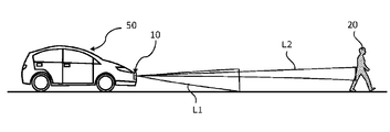
- FIG. 2 is a diagram for explaining an outline of the operation of the distance measuring device 10.
- FIG. 2 schematically shows an example of the distance measuring device 10 and an example of a distance image that can be generated by the distance measuring device 10.
- the light emitting device 100 includes a first light source 110 and a second light source 120.
- the first light source 110 is configured to emit flash light L1 as the first light.
- the second light source 120 is configured to emit the light beam L2 as the second light.
- the second light source 120 can change the emission direction of the light beam L2. Thereby, a predetermined area in the space can be scanned by the light beam L2.
- the light receiving device 200 includes an image sensor 210.
- the image sensor 210 in this example is a TOF image sensor capable of measuring a distance by TOF (Time of Flight).
- the image sensor 210 can generate a distance image of a scene to be distance-measured by using a technique of direct TOF or indirect TOF.
- the processing circuit 300 controls the first light source 110, the second light source 120, and the image sensor 210.
- the distance measuring device 10 in the present embodiment acquires distance data of a specific object such as a pedestrian, an automobile, a motorcycle, or a bicycle by using the flash light L1 and the light beam L2.
- the distance measuring device 10 changes the operation mode depending on whether or not the object exists inside the first target range 30T1 included in the range irradiated by the flash light L1.
- the first target range 30T1 is a rectangular range included in the range irradiated by the flash light L1 in the image acquired by the light receiving device 200.
- the first target range 30T1 is not limited to a rectangle, and may be a range such as an ellipse.
- the processing circuit 300 first determines the first target range 30T1 prior to the distance measurement operation.
- the first target range 30T1 can be set, for example, as a range of coordinates in a real three-dimensional space or a range of coordinates in a two-dimensional plane of an image acquired by the light receiving device 200.
- the distance measuring device 10 in this example repeats the operation of irradiating the object with the light beam L2 and acquiring the distance data.
- the operation of irradiating the object with the flash light L1 and acquiring the distance data is repeated.
- the operation of the processing circuit 300 when the object moves outside the first target range 30T1 and when the object moves inside the first target range 30T1 will be described in more detail below.
- the processing circuit 300 When the object exists outside the first target range 30T1, the processing circuit 300 causes the second light source 120 to emit the light beam L2, causes the image sensor 210 to detect the reflected light generated by the light beam L2, and causes the image sensor 210 to detect the reflected light. A second signal corresponding to the amount of detected light of each pixel is output. The processing circuit 300 generates and outputs distance data or luminance data of an object in the scene for each frame based on the second signal.
- the processing circuit 300 calculates the moving direction of the object based on the distance data or the luminance data in a plurality of frames, and causes the second light source 120 to emit the light beam L2 in accordance with the direction. As a result, the processing circuit 300 can track the range 30B of the beam spot of the light beam L2 on the object.
- the plurality of white circles shown in the right side of FIG. 2 represent an example of the range 30B of the beam spot irradiated by the light beam L2.
- the size of the beam spot range 30B changes depending on the angle of view of the scene captured by the image sensor 210, the spread angle of the light beam L2, and the distance of the object. While the object is outside the first target range 30T1, the ranging device 10 may stop emitting the flash light L1 or use the flash light L1 within the first target range 30T1. Distance data may be acquired.
- the processing circuit 300 When the object is inside the first target range 30T1, the processing circuit 300 emits the flash light L1 to the first light source 110, causes the image sensor 210 to detect the reflected light generated by the flash light L1. A first signal corresponding to the amount of detected light of each pixel is output.
- the degree of spread of the flash light L1 is larger than the degree of spread of the light beam L2, while the flash light L1 has a lower energy density as compared with the light beam L2. Therefore, the flash light L1 irradiates the first target range 30T1 which is wide at a relatively short distance.
- the processing circuit 300 repeats an operation of detecting and recording the position of an object existing in the first target range 30T1 based on the first signal.
- this operation may be expressed as "tracking an object internally". Since the flash light L1 can irradiate a relatively wide range, the emission direction of the flash light L1 can be fixed.
- the light emitting device 100 may be configured so that the emission direction of the flash light L1 can be changed.
- the processing circuit 300 outputs, for example, distance data or luminance data of an object at a predetermined frame rate.
- FIG. 3 is a perspective view schematically showing an example of a vehicle 50 in which the distance measuring device 10 is mounted on the front surface.
- the distance measuring device 10 in the vehicle 50 emits the flash light L1 and the light beam L2 toward the front of the vehicle 50.
- the mounting position of the distance measuring device 10 on the vehicle 50 is not limited to the front surface thereof, but may be the upper surface, the side surface, or the rear surface thereof. The mounting position is appropriately determined according to the direction in which the object is measured.
- FIG. 4 is a side view schematically showing an example of the vehicle 50 traveling on the road. Since the degree of spread of the light beam L2 is smaller than the degree of spread of the flash light L1, the irradiation energy density of the light beam L2 is higher than the irradiation energy density of the flash light L1. Therefore, the light beam L2 is suitable for irradiating an object 20 farther than the flash light L1. In the example shown in FIG. 4, the distant object 20 is a pedestrian, but the object 20 can be an object other than a person.
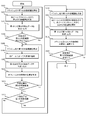
- FIG. 5 is a flowchart showing an example of a distance measuring operation when an object such as an oncoming vehicle approaches a vehicle 50 traveling on a road.
- the processing circuit 300 executes the operations of steps S101 to S114 shown in the flowchart of FIG. 5 during the distance measuring operation.
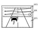
- 6A to 6E are diagrams schematically showing how an oncoming vehicle approaches a vehicle 50 traveling on a road. Time elapses in the order of FIGS. 6A to 6E. 6A to 6E schematically show an example of an image acquired by photographing a scene including an oncoming vehicle from the front of the vehicle 50.
- the lower range is the first target range 30T1 irradiated with the flash light L1, and the upper range is scanned by the light beam L2.
- the second target range is 30T2.
- the second target range 30T2 exists outside the first target range 30T1.
- the processing circuit 300 determines the first target range 30T1 and the second target range 30T2 before the distance measuring operation. The method for determining the first target range 30T1 and the second target range 30T2 will be described later. Hereinafter, the operation of each step shown in FIG. 5 will be described.
- Step S101 The processing circuit 300 causes the light emitting device 100 to irradiate the first target range 30T1 in the scene with the flash light L1.
- the degree of spread of the flash light L1 is larger than the degree of spread of the light beam L2.
- the first target range 30T1 in this example corresponds to a distance relatively closer than the second target range 30T2.
- Step S102 The processing circuit 300 scans the second target range 30T2 in the scene with the light beam L2 by causing the light emitting device 100 to continuously emit the light beam L2 while changing the light emitting direction of the light beam L2.
- the arrow shown in FIG. 6A represents the trajectory of the beam spot range 30B by scanning.
- the second target range 30T2 in this example corresponds to a distance relatively farther than the first target range 30T1.
- the processing circuit 300 causes the light receiving device 200 to detect the first reflected light generated by the irradiation of the flash light L1 and the second reflected light generated by the irradiation of the light beam L2, and causes the light receiving device 200 to detect the first signal and the second reflected light, respectively. Output the signal of.
- the processing circuit 300 generates and outputs first detection data and second detection data indicating the position or distance of the object 20 based on the first signal and the second signal, respectively.
- the processing circuit 300 stores the first detection data and the second detection data in a memory (not shown) in the processing circuit 300.
- the first detection data can be, for example, the distance data within the first target range 30T1 shown in FIG.
- the second detection data can be, for example, distance data within the range 30B of the beam spot shown in FIG.
- first distance data the distance data within the first target range 30T1
- second distance data the distance data within the beam spot range 30B
- the distance data within the first target range 30T1 and the distance data within the beam spot range 30B may be integrated and output. This integration makes it easier to grasp the distance data of the object 20 at a long distance and a short distance.
- Luminance data may be generated and output instead of distance data.
- the detection data within the range 30B of a plurality of beam spots having different irradiation directions may be integrated and output.
- the processing circuit 300 may determine the behavior of the vehicle by driving assistance or automatic driving based on the detection data such as the distance data or the luminance data of the object 20 stored in the memory in time series.
- the processing circuit 300 may display information related to the distance data of the object 20 on a display or an instrument (not shown) in the vehicle 50.
- Step S104 The processing circuit 300 determines whether or not the object 20 to be tracked exists in the second target range 30T2 based on the second detection data.
- the processing circuit 300 may determine what the object 20 is by recognizing a specific object by a known image recognition technique based on distance data or luminance data.
- a particular object is, for example, a car, a motorcycle, a bicycle, or a pedestrian.
- the priority of the objects is determined according to the type of the object, and the object having the highest priority may be the object 20.
- the processing circuit 300 repeatedly executes the operations of steps S101 to S104 to continue searching for the object 20 to be tracked. If the object 20 is within the second target range 30T2 as shown in FIG. 6A, the process proceeds to step S105.
- Step S105 The processing circuit 300 causes the light emitting device 100 to irradiate the first target range 30T1 in the scene with the flash light L1. This operation is the same as the operation in step S101.
- Step S106 The processing circuit 300 determines the emission direction of the light beam L2 based on the information regarding the position of the object 20 included in the second detection data, and causes the light emitting device 100 to irradiate the light beam L2 toward the object 20. ..
- the information about the position of the object 20 can be, for example, a distance or luminance value of the object 20.
- the processing circuit 300 detects the object 20 based on the information regarding the position of the object 20, and interrupts the scanning operation by the light beam L2 as shown in FIG. 6B. After that, the processing circuit 300 tracks the object 20 by the light beam L2 as shown in FIG. 6C in response to the detection of the object 20.
- the processing circuit 300 determines the position of the object 20 in the tracking based on the second detection data.
- the position of the object 20 may be determined using external data acquired from an external sensor such as a camera instead of the second detection data. Alternatively, both the second detection data and the external data may be used.
- Step S107 The processing circuit 300 generates and outputs the first detection data and the second detection data by executing the same operation as in step S103.
- the processing circuit 300 stores the first detection data and the second detection data in a memory (not shown) in the processing circuit 300.
- Step S108 The processing circuit 300 determines whether or not the object 20 has exited the second target range 30T2 based on the information regarding the position of the object 20 included in the second detection data. The determination can be made, for example, based on the value of the distance of the object 20 included in the second detection data. For example, when the value of the distance of the object 20 included in the second detection data is larger than the first reference value or smaller than the second reference value, the object 20 exits the second target range 30T2. It can be determined that the data has been removed.
- the first reference value and the second reference value correspond to the longest and shortest distances in the second target range 30T2 shown in FIG. 6A, respectively.
- the first reference value and the second reference value can be, for example, 200 m and 50 m, respectively.
- the determination may be made based on the brightness value of the object 20 included in the second detection data. For example, when the brightness value of the object 20 included in the second detection data is larger than the third reference value or smaller than the fourth reference value, the object 20 has exited the second target range 30T2. Can be determined.
- the third reference value and the fourth reference value correspond to the luminance values at the shortest and longest distances in the second target range 30T2 shown in FIG. 6A, respectively.
- the irradiation energy density of the light beam L2 is relatively high, and the third reference value can be, for example, 90% of the saturation value of the brightness value in the light receiving device 200.
- the fourth reference value can be, for example, 1% of the saturation value of the luminance value.
- the processing circuit 300 When the object 20 does not come out of the second target range 30T2, the processing circuit 300 repeatedly executes the operations of steps S105 to S108, and continues tracking the object 20 by the light beam L2. When the object 20 comes out of the second target range 30T2, the process proceeds to step S109.
- Step S109 When the object 20 exits the second target range 30T2 as shown in FIG. 6D, the processing circuit 300 determines whether or not the object 20 has entered the first target range 30T1. For example, when the value of the distance of the object 20 included in the second detection data is equal to or less than a predetermined reference value, it may be determined that the object 20 has entered the first target range 30T1.
- the reference value corresponds to the longest distance in the first target range 30T1, and can be, for example, 50 m.
- the value of the distance of the object 20 can be obtained based on the first detection data, it may be determined that the object 20 has entered the first target range 30T1. The determination may be made based on the brightness value of the object 20 included in the second detection data.
- the processing circuit 300 may restart the operation of step S101.
- Step S110 As shown in FIG. 6D, when the object 20 enters the first target range 30T1, the processing circuit 300 sends the first target range 30T1 in the scene to the light emitting device 100 with the flash light L1 as in step S101. Irradiate.
- Step S111 The processing circuit 300 stops tracking the object 20 by the light beam L2. After that, as shown in FIG. 6E, the processing circuit 300 scans the scan range with the light beam as in step S102.
- Step S112 Similar to step S103, the processing circuit 300 generates and outputs the first detection data and the second detection data.
- the processing circuit 300 stores the first detection data and the second detection data in a memory (not shown) in the processing circuit 300.
- Step S113 As shown in FIG. 6E, the processing circuit 300 internally tracks the object 20 by the flash light L1.
- the white arrows shown in FIG. 6E indicate that they are tracking internally.
- This operation corresponds to recording a change in the position of the object 20 in addition to the first detection data. In this respect, the operation is different from the operation of tracking the object 20 by the light beam L2.
- the degree of spread of the flash light L1 is larger than the degree of spread of the light beam L2. Therefore, the irradiation direction of the flash light L1 may be fixed. It is not always necessary to change the irradiation direction of the flash light according to the movement of the object 20.
- the processing circuit 300 determines the position of the object 20 in the tracking based on the first detection data. External data acquired from an external sensor such as a camera may be used instead of the first detection data. Alternatively, both the first detection data and the external data may be used.
- Step S114 The processing circuit 300 determines whether or not the object 20 has come out of the first target range 30T1 based on the first detection data.
- the situation where the object 20 comes out of the first target range 30T1 occurs, for example, when an oncoming vehicle passes by the vehicle 50.
- the processing circuit 300 ends the tracking of the object 20 by the flash light L1 and the light beam L2.
- the processing circuit 300 may restart the operation of step S101.
- the processing circuit 300 repeatedly executes the operations of steps S110 to S114, and continues the internal tracking of the object 20 by the flash light L1.
- the following effects can be obtained by the operations of steps S101 to S114 in the first embodiment. That is, when the object 20 moves to the first target range 30T1 existing near the vehicle 50, the processing circuit 300 does not need to track the object 20 by the light beam L2. Therefore, the processing circuit 300 can efficiently track the distant object 20 moving in the second target range 30T2 by the light beam L2. As a result, data indicating the position of the object 20 in the distance measurement target scene can be efficiently acquired, and the amount of the data can be increased. Further, the necessary data can be acquired in a short time as compared with the configuration in which the entire scene to be distanced is scanned by the light beam L2.
- FIG. 7 is a flowchart of a distance measuring operation according to the second embodiment of the present disclosure when the preceding vehicle moves away from the vehicle 50 traveling on the road.
- the processing circuit 300 executes the operations of steps S201 to S214 shown in the flowchart of FIG. 7 during the distance measuring operation.
- 8A to 8E are diagrams schematically showing how the preceding vehicle moves away from the vehicle 50 traveling on the road. Time elapses in the order of FIGS. 8A to 8E.
- the operation of each step shown in FIG. 7 will be described.
- Step S201 The processing circuit 300 causes the light emitting device 100 to irradiate the first target range 30T1 in the scene with the flash light L1. This operation is the same as the operation of step S101 in the first embodiment.
- Step S202 The processing circuit 300 causes the light emitting device 100 to change the emission direction of the light beam L2 and irradiate the second target range 30T2 in the scene while scanning with the light beam L2. This operation is the same as the operation of step S102 in the first embodiment.
- Step S203 The processing circuit 300 causes the light receiving device 200 to detect the first reflected light generated by the irradiation of the flash light L1 and the second reflected light generated by the irradiation of the light beam L2, and causes the light receiving device 200 to detect the first signal and the second reflected light, respectively. Output the signal of.
- the processing circuit 300 generates and outputs first detection data and second detection data indicating the position of the object 20 based on the first signal and the second signal. This operation is the same as the operation of step S103 in the first embodiment.
- Step S204 The processing circuit 300 determines whether or not the object 20 to be tracked exists in the first target range 30T1 based on the first detection data.
- the method for determining what the object 20 is is as described in step S104 in the first embodiment.
- the processing circuit 300 repeats the operations of steps S201 to S204 to continue the search for the object 20 to be tracked.
- Step S205 When the object 20 exists in the first target range 30T1 as shown in FIG. 8A, the processing circuit 300 executes the same operation as in step S201.
- Step S206 The processing circuit 300 executes the same operation as in step S202.
- Step S207 The processing circuit 300 executes the same operation as in step S203.
- Step S208 As shown in FIG. 8B, the processing circuit 300 internally tracks the object 20 by the flash light L1. This operation is the same as the operation of step S113 in the first embodiment.
- Step S209 The processing circuit 300 determines whether or not the object 20 has exited the first target range 30T1 based on the information regarding the position of the object 20 included in the first detection data. For example, when the distance value of the object 20 included in the first detection data is equal to or greater than a predetermined reference value, it may be determined that the object 20 has exited the first target range 30T1.
- the reference value corresponds to the longest distance value in the first target range 30T1.
- the reference value of the distance value can be, for example, 50 m.
- the value of the distance of the object 20 cannot be obtained based on the first detection data, it may be determined that the object 20 has exited the first target range 30T1.
- the determination may be made based on the brightness value of the object 20 included in the first detection data. For example, when the brightness value of the object 20 is equal to or less than a predetermined reference value, it may be determined that the object 20 has come out of the first target range 30T1. This reference value corresponds to the brightness value at the longest distance value in the first target range 30T1.
- the irradiation energy density of the flash light L1 is relatively low, and the reference value of the brightness value can be, for example, 10% of the saturation value of the brightness value.
- Step S210 When the object 20 exits the first target range 30T1 as shown in FIG. 8C, the processing circuit 300 determines whether or not the object 20 has entered the second target range 30T2. The determination can be made, for example, based on the value of the distance of the object 20 included in the second detection data. For example, when the value of the distance of the object 20 included in the second detection data is larger than the first reference value or smaller than the second reference value, the object 20 exits the second target range 30T2. It can be determined that the data has been removed.
- the first reference value and the second reference value correspond to the longest and shortest distances in the second target range 30T2 shown in FIG. 8A, respectively.
- the first reference value and the second reference value can be, for example, 200 m and 50 m, respectively.
- the determination may be made based on the brightness value of the object 20 included in the second detection data. For example, when the brightness value of the object 20 included in the second detection data is larger than the third reference value or smaller than the fourth reference value, the object 20 has exited the second target range 30T2. Can be determined.
- the third reference value and the fourth reference value correspond to the luminance values at the shortest and longest distances in the second target range 30T2 shown in FIG. 8A, respectively.
- the third reference value and the fourth reference value can be, for example, 90% and 1% of the saturation value of the luminance value, respectively.
- the processing circuit 300 ends the tracking of the object 20 by the flash light L1 and the light beam L2.
- a situation in which the object 20 exits the first target range 30T1 but does not enter the second target range 30T2 occurs, for example, when the object 20 crosses a road.
- the processing circuit 300 may restart the operation of step S201.
- Step S211 The processing circuit 300 executes the same operation as in step S201.
- Step S212 The processing circuit 300 determines the emission direction of the light beam L2 based on the information regarding the position of the object 20 included in the second detection data, and causes the light emitting device 100 to irradiate the light beam L2 toward the object 20. .. In other words, the processing circuit 300 interrupts the scanning operation by the light beam L2 as shown in FIG. 8C, and tracks the object 20 by the light beam L2 as shown in FIG. 8D.
- Step S213 The processing circuit 300 executes the same operation as in step S203.
- Step S214 The processing circuit 300 determines whether or not the object 20 has come out of the second target range 30T2 based on the second detection data. When the object 20 comes out of the second target range 30T2, the processing circuit 300 ends the tracking of the object 20 by the flash light L1 and the light beam L2. The processing circuit 300 may restart the operation of step S201. When the object 20 does not go out of the second target range 30T2, the processing circuit 300 repeatedly executes the operations of steps S211 to S214, and continues tracking the object 20 by the light beam L2.
- steps S201 to S214 in the second embodiment By the operation of steps S201 to S214 in the second embodiment, the same effect as that of the first embodiment can be obtained.
- both an oncoming vehicle approaching the vehicle 50 as in the first embodiment and a preceding vehicle moving away from the vehicle 50 as in the second embodiment can exist at the same time.
- one distance measuring device 10 mounted on the vehicle 50 separates the first operation of measuring the distance of the oncoming vehicle approaching the vehicle 50 and the second operation of measuring the distance of the preceding vehicle away from the vehicle 50. You may execute it with.
- the one distance measuring device 10 may alternately execute the first operation and the second operation for each frame, execute the first operation for a predetermined number of frames, and then execute the second operation for a predetermined number of frames. You may.
- the first operation and the second operation may be interchanged.
- the vehicle 50 is equipped with two ranging devices 10, one of the two ranging devices 10 measures the oncoming vehicle approaching the vehicle 50, and the other measures the distance of the preceding vehicle moving away from the vehicle 50. You may.
- the first target range 30T1 may be determined based on the distance value.
- the first target range 30T1 may have a distance value within a range of 20 m or more and 50 m or less from the distance measuring device 10.
- the first target range 30T1 may be determined based on the brightness value of the reflected light from the object 20.
- the reason is that the intensity of the illumination light is not uniform within the irradiation range, especially in the case of flash light. Another reason is that even if the objects 20 are at the same distance, they are detected by the image sensor 210 depending on the reflectance or scattering property of the object 20 or the direction of the normal on the surface of the object 20.
- the brightness value of the reflected light changes.
- An example of the brightness value of the reflected light is the brightness value of the reflected light from the object 20 generated by the irradiation of the flash light L1.
- the irradiation energy density of the flash light L1 is relatively low, and the first target range 30T1 may have a brightness value of the reflected light in a range of 10% or more of the saturation value of the brightness value.
- the brightness value of the reflected light is the brightness value of the reflected light from the object 20 generated by the irradiation of the light beam L2.
- the irradiation energy density of the light beam L2 is relatively high, and the first target range 30T1 may have a brightness value of the reflected light in a range of 90% or more of the saturation value of the brightness value.
- the first target range 30T1 may be determined based on at least one selected from the group consisting of the first detection data, the second detection data, and the external data.
- the first reference value and the second reference value of the above-mentioned distance value are determined from the distance data obtained from at least one selected from the group consisting of the first detection data, the second detection data, and the external data. You may. Further, from the luminance data obtained from at least one selected from the group consisting of the first detection data, the second detection data, and the external data, the third reference value and the second reference value of the above-mentioned luminance values are used. You may decide.
- the first target range 30T1 may be determined based on the reliability of the position of the object 20.
- the reliability of the position of the object 20 is determined based on, for example, at least one selected from a group consisting of a plurality of first detection data, a plurality of second detection data, and a plurality of external data. It can be defined by the dispersion of the positions of the objects 20.
- the processing circuit 300 generates and outputs the first detection data or the second detection data a plurality of times, or acquires the external data from an external device a plurality of times to calculate the reliability of the position of the object 20. .. It is considered that the reliability of the position of the object 20 is low in the range where the variance of the position of the object 20 is larger than the predetermined reference value. Therefore, the range in which the variance is equal to or greater than a predetermined reference value may be set as the first target range 30T1.
- the first target range 30T1 may be determined based on at least one selected from the group consisting of the luminance value, the distance value, and the external data, or may be appropriately changed.
- the second target range 30T2 may be determined by the same method as the first target range 30T1.
- the second target range 30T2 can be, for example, a distance value within a range of 50 m or more and 200 m or less from the distance measuring device 10.
- the second target range 30T2 may be, for example, a range in which the brightness value of the reflected light generated by the irradiation of the light beam L2 is 1% or more and 90% or less of the saturation value of the brightness value.
- the second target range 30T2 is, for example, a range not included in the first target range 30T1 and can generate distance data or luminance data by the reflected light generated by the irradiation of the light beam L2. Range can be.
- FIG. 9 shows the emission timing of the flash light L1 and the light beam L2 emitted from the light emitting device 100 in one frame, the incident timing of the first reflected light and the second reflected light on the light receiving device 200, and the light receiving device. It is a figure which shows typically the 1st example with the exposure timing of 200. In the example shown in FIG. 9, the operation of the indirect TOF is described.
- the exposure period for light detection by the image sensor 210 is set to three times the light emission period ⁇ t of the flash light L1 and the light beam L2.
- the amount of light detected by the light receiving device 200 in the first to third periods obtained by dividing the exposure period into three equal parts is A0 to A2, respectively.
- ⁇ be the difference between the timing of the start of light emission and the timing of the start of exposure.
- Processing circuit 300 utilizes the indirect TOF technology, the detected light A2, and the timing difference t 0 from the detected light intensity A0, calculates the distance to the object 20.
- ⁇ be the round-trip time until the flash light L1 and the light beam L2 are emitted, reflected by the object 20, and returned as the first reflected light and the second reflected light, respectively, and the speed of light in the air is c.
- the distance to the object 20 is c ⁇ / 2.
- A2 in this equation corresponds to the amount of detected noise light contained in A0 and A1.
- A0 in this equation corresponds to the amount of detected noise light contained in A1 and A2. Depending on the application, the amount of detected noise light may not be considered.
- the processing circuit 300 causes the light emitting device 100 to simultaneously emit the flash light L1 and the light beam L2, and the image sensor 210 detects the first reflected light and the second reflected light within the same exposure period. Let me. By this operation, the number of exposures per frame can be increased. As a result, the S / N of the signal detected by the image sensor 210 can be improved, and high-precision distance measurement becomes possible.
- the timing at which the first reflected light is incident on the light receiving device 200 and the second The time difference from the timing at which the reflected light enters the light receiving device 200 can be large.
- the first reflected light and the second reflected light can be detected within a common exposure period by temporally shifting the light emission timing of the flash light L1 and the light emission timing of the light beam L2.
- FIG. 10 shows the emission timing of the flash light L1 and the light beam L2 emitted from the light emitting device 100 in one frame, the incident timing of the first reflected light and the second reflected light on the light receiving device 200, and the light receiving device. It is a figure which shows typically the 2nd example with the exposure timing of 200.
- the light emitting operation of the flash light L1 and the exposure operation of the first reflected light are independent of the light emitting operation of the light beam L2 and the exposure operation of the second reflected light.
- the exposure period for detecting the first reflected light and the exposure period for detecting the second reflected light can be set independently. Therefore, even if the distance at which the object 20 is measured by the flash light L1 and the distance at which the object 20 is measured by the light beam L2 are significantly different, the object 20 can be measured without any problem.
- FIG. 11 is a flowchart of the distance measuring operation in the modified example of the first embodiment.
- the difference between the modified example of the first embodiment and the first embodiment is the operation of steps S121 to S123.
- Step S121 The processing circuit 300 predicts the future position of the object 20 based on the information regarding the position of the object 20 included in the second detection data.
- the "future" may be the next frame or a plurality of frames ahead.
- the future position of the object 20 can be predicted, for example, as follows.
- the movement vector of the object 20 in the three-dimensional space may be calculated from the distance data to the current frame acquired by the repetitive motion, and the future position of the object 20 may be predicted based on the movement vector. ..
- the optical flow of the object 20 may be calculated from the luminance data up to the current frame acquired by the repetitive operation, and the future position of the object 20 may be predicted based on the optical flow.
- Step S122 The processing circuit 300 determines whether or not the predicted position of the object 20 exists outside the second target range 30T2. When the predicted position of the object 20 does not exist outside the second target range 30T2, the processing circuit 300 repeatedly executes the operations of steps S105 to S122, and continues tracking the object 20 by the light beam L2.
- Step S123 When the predicted position of the object 20 exists outside the second target range 30T2, the processing circuit 300 determines whether or not the predicted position exists within the first target range 30T1. The determination criteria are as described in step S109 of the first embodiment. When the object 20 does not exist within the first target range 30T1, the processing circuit 300 ends the tracking of the object 20 by the flash light L1 and the light beam L2. The processing circuit 300 may restart the operation of step S101.
- the following effects can be obtained by the operations of steps S121 to S123 in the modified example of the first embodiment. That is, when the object 20 moves from the second target range 30T2 to the first target range 30T1, it is possible to reduce the overhead time of simultaneously irradiating the object 20 with the flash light L1 and the light beam L2. As a result, data indicating the position of the object 20 in the distance measurement target scene can be acquired more efficiently, and the amount of the data can be further increased.
- FIG. 12 is a flowchart of the distance measuring operation in the modified example of the second embodiment.
- the difference between the modified example of the second embodiment and the second embodiment is the operation of steps S221 to S223.
- Step S221 The processing circuit 300 predicts the position of the object 20 in the future based on the information of the object 20 included in the first detection data.
- the position of the object 20 is predicted as described in step S121 in the modified example of the first embodiment.
- Step S222 The processing circuit 300 determines whether or not the predicted position of the object 20 exists outside the first target range 30T1. When the predicted position of the object 20 does not exist outside the first target range 30T1, the processing circuit 300 repeatedly executes the operations of steps S205 to S222 to perform internal tracking of the object 20 by the flash light L1. continue.
- Step S223 When the predicted position of the object 20 is outside the first target range 30T1, the processing circuit 300 determines whether or not the predicted position is within the second target range 30T2. The determination criteria are as described in step S210 in the second embodiment. When the predicted position of the object 20 does not exist in the second target range 30T2, the processing circuit 300 ends the tracking of the object 20 by the flash light L1 and the light beam L2. The processing circuit 300 may restart the operation of step S201.
- the distance measuring devices according to the first and second embodiments of the present disclosure are described below for each item.
- the distance measuring device may emit a first light and a second light having a smaller degree of spread than the first light, and may change the emission direction of the second light. It includes a possible light emitting device, a light receiving device, and a processing circuit that controls the light emitting device and the light receiving device and processes a signal output from the light receiving device.
- the processing circuit generates first distance data based on the first signal obtained by the light receiving device detecting the first reflected light generated by the first light, and the light receiving device generates the first distance data.
- a second distance data is generated based on the second signal obtained by detecting the second reflected light generated by the second light, and the range in which the object is irradiated by the first light.
- this distance measuring device it is possible to efficiently acquire the distance data of an object entering from the outside to the inside of the first target range in the distance measuring target scene.
- the distance measuring device is the distance measuring device according to the first item, in which the processing circuit performs the first distance data after the object enters the inside of the first target range. In addition, the change in the position of the object is recorded.
- this ranging device it is possible to internally track an object that has entered the inside of the first target range.
- the distance measuring device is a second target range in which the processing circuit is provided to the light emitting device outside the first target range in the distance measuring device according to the first or second item. Is scanned by the second light, the object is detected based on the second signal or the second distance data obtained by the scan, and the object is detected. The light emitting device is made to start tracking the object by the second light. With this ranging device, it is possible to track an object in the second target range.
- the ranging device may emit a first light and a second light having a smaller degree of spread than the first light, and may change the emission direction of the second light. It includes a possible light emitting device, a light receiving device, and a processing circuit that controls the light emitting device and the light receiving device and processes a signal output from the light receiving device.
- the processing circuit generates first distance data based on the first signal obtained by the light receiving device detecting the first reflected light generated by the first light, and the light receiving device generates the first distance data.
- Second distance data is generated based on the second signal obtained by detecting the second reflected light generated by the second light, and the object is included in the range irradiated by the first light.
- the change in the position of the target is recorded in addition to the first distance data, and the target moves from the inside to the outside of the first target range. Then, the light emitting device is made to start tracking the object by the second light.
- this distance measuring device it is possible to efficiently acquire distance data of an object moving from the inside to the outside of the first target range in the distance measuring target scene.
- the distance measuring device is the distance measuring device according to any one of the first to fourth items, and when the object is outside the first target range, the processing circuit is used. Distance measurement by the first light is performed.
- the distance measuring device is the distance measuring device according to any one of the first to fifth items, in which the processing circuit is such that the object is outside or inside the first target range. From the group consisting of the strength of the first signal, the strength of the second signal, the first distance data, the second distance data, and the external data input from the external sensor. Determined based on at least one selected.
- the position of the object can be determined by at least one selected from the group consisting of the brightness value, the distance value, and the external data.
- the distance measuring device is the distance measuring device according to any one of the first to sixth items, in which the processing circuit moves from the outside to the inside of the first target range of the object. , And the movement from the inside to the outside, the strength of the first signal, the strength of the second signal, the first distance data, the second distance data, and the external data input from the external sensor. Predict based on at least one selected from the group consisting of.
- the above movement of the object can be determined by at least one selected from the group consisting of the luminance value, the distance value, and the external data.
- the distance measuring device is an image sensor in which the light receiving device has a plurality of pixels arranged two-dimensionally in the distance measuring device according to any one of the first to seventh items.
- this ranging device it is possible to acquire ranging image data or luminance image data of an object.
- the distance measuring device is the distance measuring device according to the first item, wherein the processing circuit has the strength of the first signal, the strength of the second signal, the first distance data, and the like.
- the first target range is changed based on at least one selected from the group consisting of the second distance data and the external data input from the external sensor.
- the first target range is determined based on at least one selected from the distance value, the brightness value, and the external data.
- the distance measuring device is the distance measuring device according to the eighth item, wherein the processing circuit has the strength of the first signal, the strength of the second signal, the first distance data, and the like.
- the position of the object is detected based on at least one selected from the group consisting of the second distance data and the external data, and the reliability of the position of the object defined by the dispersion of the position of the object.
- the degree is calculated, and the first target range is determined based on the reliability of the position of the object.
- the first target range is determined based on the reliability of the position of the object.
- the distance measuring device is the distance measuring device according to any one of the first to tenth items, in which the processing circuit integrates the first distance data and the second distance data. Output.
- This distance measuring device makes it easy to grasp the distance data of an object at a long distance and a short distance.
- the distance measuring device is the distance measuring device according to any one of the first to eleventh items, wherein the first light is flash light and the second light is an optical beam.
- this distance measuring device it is possible to efficiently acquire distance data of an object by flash light and light beam having greatly different irradiation ranges.
- the program according to the thirteenth item can emit the first light and the second light having a smaller degree of spread than the first light, and can change the emission direction of the second light.
- a program used in a distance measuring device including a light emitting device, a light receiving device, a processing circuit that controls the light emitting device and the light receiving device, and processes a signal output from the light receiving device, and is a processing circuit.
- the light receiving device generates the first distance data based on the first signal obtained by detecting the first reflected light generated by the first light, and the light receiving device is said to be said.
- the second distance data is generated based on the second signal obtained by detecting the second reflected light generated by the second light, and the object is irradiated with the first light.
- the light emitting device When the object is outside the first target range included in the range, the light emitting device is made to track the object by the second light, and the object is moved from the outside to the inside of the first target range. Upon entering, the light emitting device is made to stop the tracking by the second light.
- This program makes it possible to efficiently acquire the distance data of an object entering from the outside to the inside of the first target range in the distance measurement target scene.
- the program according to the fourteenth item can emit the first light and the second light having a smaller degree of spread than the first light, and can change the emission direction of the second light.
- a program used in a distance measuring device including a light emitting device, a light receiving device, a processing circuit that controls the light emitting device and the light receiving device, and processes a signal output from the light receiving device, and is a processing circuit.
- the light receiving device generates the first distance data based on the first signal obtained by detecting the first reflected light generated by the first light
- the light receiving device generates the first distance data.
- To generate the second distance data based on the second signal obtained by detecting the second reflected light generated by the second light, and to the range where the object is irradiated by the first light.
- the change in the position of the object is recorded in addition to the first distance data, and the object is from the inside of the first target range.
- it moves to the outside, it causes the light emitting device to start tracking the object by the second light.
- This program makes it possible to efficiently acquire the distance data of an object moving from the inside to the outside of the first target range in the distance measurement target scene.
- the ranging device in the present disclosure can be used, for example, for applications of a LiDAR system mounted on a vehicle such as an automobile, an AGV (automated guided vehicle), and an air vehicle such as a UAV (unmanned aerial vehicle).
- a LiDAR system mounted on a vehicle such as an automobile, an AGV (automated guided vehicle), and an air vehicle such as a UAV (unmanned aerial vehicle).
- the ranging device in the present disclosure can also be applied to, for example, a monitoring system attached to a building.
Abstract
A distance measuring device according to the present invention is provided with: a light emitting device which is capable of emitting first light and second light that spreads less than the first light and changing the emission direction of the second light; a light receiving device; and a processing circuit which controls the light emitting device and the light receiving device and processes signals output from the light receiving device, wherein the light receiving device detects reflected light produced by the first light and the second light and generates first distance data and second distance data, respectively, and the processing circuit causes the light emitting device to track an object with the second light when the object is outside a first target range included in the range irradiated with the first light, and causes the light emitting device to stop the tracking with the second light when the object enters the first target range from outside the first target range.
Description
本開示は、測距装置に関する。
This disclosure relates to a distance measuring device.
従来、物体に光を照射し、当該物体からの反射光を検出することにより、当該物体の位置または距離に関するデータを取得する種々のデバイスが提案されている。
Conventionally, various devices have been proposed that acquire data on the position or distance of an object by irradiating the object with light and detecting the reflected light from the object.
例えば特許文献1は、光源を含む投光系と、投光系から投光され物体で反射された光を受光する光検出器を含む受光系と、光検出器の出力信号が入力される信号処理系と、制御系とを備える物体検出装置を開示している。制御系は、投光系の投光範囲内の少なくとも1つの領域を注目領域として設定し、投光系の投光条件または信号処理系の処理条件を、注目領域に投光するときと注目領域以外の領域に投光するときとで異なるように制御する。
For example, Patent Document 1 describes a light projecting system including a light source, a light receiving system including a photodetector that receives light projected from the light source system and reflected by an object, and a signal to which an output signal of the photodetector is input. An object detection device including a processing system and a control system is disclosed. The control system sets at least one region within the light projection range of the light projection system as a region of interest, and when the light projection condition of the light projection system or the processing condition of the signal processing system is projected onto the region of interest and the region of interest. It is controlled so as to be different from when the light is projected to an area other than the above.
特許文献2は、LiDAR(Light Detection and Ranging)装置を開示している。当該LiDAR装置は、第1のビームスキャナと、第2のビームスキャナと、コントローラとを備える。第1のビームスキャナは、第1のスキャンパターンの第1のレーザビームで第1の領域をスキャンする。第2のビームスキャナは、第2のスキャンパターンの第2のレーザビームで、第1の領域よりも狭い第2の領域をスキャンする。コントローラは、第1のビームスキャナを駆動して第1の領域をスキャンし、第1のレーザビームによる反射光のデータを取得する。当該データから、1つ以上の対象物を決定し、第2のビームスキャナを駆動して第2の領域内を照射することにより、当該対象物をモニターする。
Patent Document 2 discloses a LiDAR (Light Detection and Ringing) device. The LiDAR device includes a first beam scanner, a second beam scanner, and a controller. The first beam scanner scans the first region with the first laser beam of the first scan pattern. The second beam scanner scans a second region narrower than the first region with the second laser beam of the second scan pattern. The controller drives the first beam scanner to scan the first region and acquire the data of the reflected light from the first laser beam. One or more objects are determined from the data, and the objects are monitored by driving the second beam scanner to irradiate the inside of the second region.
特許文献3は、測距撮像装置を開示している。この測距撮像装置は、パッシブ光を検出するイメージセンサから出力された信号に基づき、撮像対象エリア全体の中から測距を必要とする被写体を特定する。この測距撮像装置は、当該被写体をレーザ光で照射し、その反射光を検出することにより、当該被写体までの距離を計測する。
Patent Document 3 discloses a ranging imaging device. Based on the signal output from the image sensor that detects passive light, this range-finding imaging device identifies a subject that requires range-finding from the entire imaging target area. This distance measuring image pickup device measures the distance to the subject by irradiating the subject with a laser beam and detecting the reflected light.
特許文献4は、光ビームによって空間を走査し、イメージセンサによって物体からの反射光を受光して距離情報を取得する装置を開示している。
Patent Document 4 discloses a device that scans a space with an optical beam and receives reflected light from an object with an image sensor to acquire distance information.
本開示は、測距対象シーンにおける対象物の距離データを効率的に取得することを可能にする技術を提供する。
The present disclosure provides a technique that enables efficient acquisition of distance data of an object in a distance measurement target scene.
本開示の一態様に係る測距装置は、第1の光、および前記第1の光よりも広がりの程度が小さい第2の光を出射し、前記第2の光の出射方向を変化させることが可能な発光装置と、受光装置と、前記発光装置および前記受光装置を制御し、前記受光装置から出力された信号を処理する処理回路と、を備え、前記処理回路は、前記受光装置が前記第1の光によって生じた第1の反射光を検出することにより得られた第1の信号に基づいて第1の距離データを生成し、前記受光装置が前記第2の光によって生じた第2の反射光を検出することにより得られた第2の信号に基づいて第2の距離データを生成し、対象物が前記第1の光によって照射される範囲に含まれる第1の対象範囲の外側に存在するとき、前記発光装置に前記第2の光によって前記対象物を追尾させ、前記対象物が前記第1の対象範囲の外側から内側に進入したとき、前記発光装置に前記第2の光による前記追尾を停止させる。
The ranging device according to one aspect of the present disclosure emits a first light and a second light having a smaller degree of spread than the first light, and changes the emission direction of the second light. The processing circuit includes a light emitting device capable of generating light, a light receiving device, and a processing circuit that controls the light emitting device and the light receiving device and processes a signal output from the light receiving device. The first distance data is generated based on the first signal obtained by detecting the first reflected light generated by the first light, and the light receiving device is generated by the second light. The second distance data is generated based on the second signal obtained by detecting the reflected light of the object, and the object is outside the first target range included in the range irradiated by the first light. When the light emitting device is made to track the object by the second light and the object enters from the outside to the inside of the first target range, the second light is emitted to the light emitting device. Stops the tracking by.
本開示の包括的または具体的な態様は、システム、装置、方法、集積回路、コンピュータプログラムまたはコンピュータ読み取り可能な記録ディスク等の記録媒体で実現されてもよく、システム、装置、方法、集積回路、コンピュータプログラムおよび記録媒体の任意の組み合わせで実現されてもよい。コンピュータ読み取り可能な記録媒体は、例えばCD-ROM(Compact Disc‐Read Only Memory)等の不揮発性の記録媒体を含み得る。装置は、1つ以上の装置で構成されてもよい。装置が2つ以上の装置で構成される場合、当該2つ以上の装置は、1つの機器内に配置されてもよく、分離した2つ以上の機器内に分かれて配置されてもよい。本明細書および特許請求の範囲では、「装置」とは、1つの装置を意味し得るだけでなく、複数の装置からなるシステムも意味し得る。
Comprehensive or specific embodiments of the present disclosure may be implemented in recording media such as systems, devices, methods, integrated circuits, computer programs or computer readable recording disks, systems, devices, methods, integrated circuits, etc. It may be realized by any combination of a computer program and a recording medium. The computer-readable recording medium may include a non-volatile recording medium such as a CD-ROM (Compact Disc-Read Only Memory). The device may consist of one or more devices. When the device is composed of two or more devices, the two or more devices may be arranged in one device, or may be separately arranged in two or more separated devices. As used herein and in the claims, "device" can mean not only one device, but also a system of multiple devices.
本開示の実施形態によれば、測距対象シーンにおける対象物の距離データを効率的に取得することが可能になる。
According to the embodiment of the present disclosure, it is possible to efficiently acquire the distance data of the object in the distance measurement target scene.
以下、本開示の例示的な実施形態を説明する。なお、以下で説明する実施形態は、いずれも包括的又は具体的な例を示すものである。以下の実施形態で示される数値、形状、構成要素、構成要素の配置位置及び接続形態、ステップ、ステップの順序などは、一例であり、本開示を限定する主旨ではない。また、以下の実施形態における構成要素のうち、最上位概念を示す独立請求項に記載されていない構成要素については、任意の構成要素として説明される。また、各図は模式図であり、必ずしも厳密に図示されたものではない。さらに、各図において、実質的に同一の構成要素に対しては同一の符号を付しており、重複する説明は省略又は簡略化される場合がある。
Hereinafter, exemplary embodiments of the present disclosure will be described. It should be noted that all of the embodiments described below show comprehensive or specific examples. Numerical values, shapes, components, arrangement positions and connection forms of components, steps, order of steps, etc. shown in the following embodiments are examples, and are not intended to limit the present disclosure. Further, among the components in the following embodiments, the components not described in the independent claims indicating the highest level concept are described as arbitrary components. Further, each figure is a schematic view and is not necessarily exactly illustrated. Further, in each figure, substantially the same components are designated by the same reference numerals, and duplicate description may be omitted or simplified.
まず、図1から図4を参照して、本開示の例示的な実施形態を簡単に説明する。
First, an exemplary embodiment of the present disclosure will be briefly described with reference to FIGS. 1 to 4.
図1は、本開示の例示的な実施形態による測距装置10の概略的な構成を示すブロック図である。本実施形態における測距装置10は、発光装置100と、受光装置200と、処理回路300とを備える。測距装置10は、例えば車両に搭載されるLiDARシステムの一部として利用され得る。測距装置10は、測距対象のシーンを光で照射し、距離データを生成して出力するように構成されている。なお、本開示における「距離データ」とは、計測点の基準点からの絶対的な距離、または計測点間の相対的な深度を表す様々なデータを意味する。距離データは、例えば、距離画像データであってもよいし、3次元点群データであってもよい。距離データは、直接的に距離または深度を表すデータに限られず、距離または深度を算出するためのセンサデータそのもの、すなわちRawデータであってもよい。Rawデータは、例えば受光装置200が受けた光の強度に基づき生成した輝度データであり得る。輝度データは、例えば、輝度画像データであってもよい。
FIG. 1 is a block diagram showing a schematic configuration of a distance measuring device 10 according to an exemplary embodiment of the present disclosure. The distance measuring device 10 in the present embodiment includes a light emitting device 100, a light receiving device 200, and a processing circuit 300. The ranging device 10 can be used, for example, as part of a LiDAR system mounted on a vehicle. The distance measuring device 10 is configured to irradiate a scene to be measured with light to generate and output distance data. The "distance data" in the present disclosure means various data representing the absolute distance of the measurement point from the reference point or the relative depth between the measurement points. The distance data may be, for example, distance image data or three-dimensional point cloud data. The distance data is not limited to data that directly represents the distance or depth, and may be sensor data itself for calculating the distance or depth, that is, Raw data. Raw data may be, for example, luminance data generated based on the intensity of light received by the light receiving device 200. The luminance data may be, for example, luminance image data.
発光装置100は、広がりの程度の異なる複数種類の光を出射する。例えば、シーンに向けて相対的に広がりの大きい光ビームまたはフラッシュ光を照射したり、シーン中の特定の対象物に向けて広がりの小さい光ビームを照射したりすることができる。言い替えれば、発光装置100は、相対的にブロードな第1の光と、第1の光の照射範囲よりも狭い範囲を照射する第2の光を出射することができる。発光装置100は、第1の光を出射する第1の光源と、第2の光を出射する第2の光源とを備えていてもよい。あるいは、発光装置100は、第1の光および第2の光の両方を出射することが可能な1つの光源を備えていてもよい。
The light emitting device 100 emits a plurality of types of light having different degrees of spread. For example, it is possible to irradiate a light beam or flash light having a relatively large spread toward a scene, or to irradiate a light beam having a small spread toward a specific object in the scene. In other words, the light emitting device 100 can emit a relatively broad first light and a second light that irradiates a range narrower than the irradiation range of the first light. The light emitting device 100 may include a first light source that emits a first light and a second light source that emits a second light. Alternatively, the light emitting device 100 may include one light source capable of emitting both the first light and the second light.
受光装置200は、発光装置100から出射された光によって生じた反射光を検出し、反射光の強度に応じた信号を出力する。受光装置200は、例えば1つ以上のイメージセンサを備える。2次元に配列された複数の光検出セル(以下、画素とも称する。)を有するイメージセンサから出力された信号は、反射光の2次元強度分布の情報を含む。受光装置200は、第1の光の照射によって生じた第1の反射光を検出して第1の反射光の強度に応じた第1の信号を出力する。受光装置200はまた、第2の光の照射によって生じた第2の反射光を検出して第2の反射光の強度に応じた第2の信号を出力する。受光装置200は、第1の反射光を検出して第1の信号を出力する第1イメージセンサと、第2の反射光を検出して第2の信号を出力する第2イメージセンサとを備えていてもよい。あるいは、受光装置200は、第1の反射光および第2の反射光を検出して第1の信号および第2の信号をそれぞれ出力することが可能な1つのイメージセンサを備えていてもよい。受光装置200が1つのセンサを備える場合、受光装置200の構成を簡略化できる。
The light receiving device 200 detects the reflected light generated by the light emitted from the light emitting device 100 and outputs a signal corresponding to the intensity of the reflected light. The light receiving device 200 includes, for example, one or more image sensors. The signal output from the image sensor having a plurality of photodetection cells (hereinafter, also referred to as pixels) arranged in two dimensions includes information on the two-dimensional intensity distribution of the reflected light. The light receiving device 200 detects the first reflected light generated by the irradiation of the first light and outputs a first signal corresponding to the intensity of the first reflected light. The light receiving device 200 also detects the second reflected light generated by the irradiation of the second light and outputs a second signal according to the intensity of the second reflected light. The light receiving device 200 includes a first image sensor that detects the first reflected light and outputs the first signal, and a second image sensor that detects the second reflected light and outputs the second signal. You may be. Alternatively, the light receiving device 200 may include one image sensor capable of detecting the first reflected light and the second reflected light and outputting the first signal and the second signal, respectively. When the light receiving device 200 includes one sensor, the configuration of the light receiving device 200 can be simplified.
処理回路300は、発光装置100および受光装置200を制御し、受光装置200から出力された信号を処理する。処理回路300は、1つ以上のプロセッサと、1つ以上の記録媒体とを含む。記録媒体は、例えばRAMおよびROMなどのメモリを含む。記録媒体には、プロセッサによって実行されるコンピュータプログラム、および処理の過程で生じた種々のデータが格納され得る。処理回路300は、複数の回路の集合体であってもよい。例えば、処理回路300は、発光装置100および受光装置200を制御する制御回路と、受光装置200から出力された信号を処理する信号処理回路とを含んでいてもよい。
The processing circuit 300 controls the light emitting device 100 and the light receiving device 200, and processes the signal output from the light receiving device 200. The processing circuit 300 includes one or more processors and one or more recording media. The recording medium includes, for example, a memory such as RAM and ROM. The recording medium can store a computer program executed by the processor and various data generated in the process. The processing circuit 300 may be an aggregate of a plurality of circuits. For example, the processing circuit 300 may include a control circuit that controls the light emitting device 100 and the light receiving device 200, and a signal processing circuit that processes a signal output from the light receiving device 200.
処理回路300は、発光装置100および受光装置200とは別の筐体に内蔵されてもよい。また、処理回路は、発光装置100および受光装置200とは離れた場所に設置され、無線通信により発光装置100および受光装置200を遠隔制御してもよい。
The processing circuit 300 may be built in a housing different from the light emitting device 100 and the light receiving device 200. Further, the processing circuit may be installed at a place away from the light emitting device 100 and the light receiving device 200, and the light emitting device 100 and the light receiving device 200 may be remotely controlled by wireless communication.
図2は、測距装置10の動作の概要を説明するための図である。図2には、測距装置10の一例と、測距装置10によって生成され得る距離画像の一例とが模式的に示されている。図2に示す例において、発光装置100は、第1の光源110と、第2の光源120とを備える。第1の光源110は、第1の光として、フラッシュ光L1を出射するように構成されている。第2の光源120は、第2の光として、光ビームL2を出射するように構成されている。第2の光源120は、光ビームL2の出射方向を変化させることができる。これにより、空間中の所定の領域を光ビームL2でスキャンすることもできる。受光装置200は、イメージセンサ210を備える。この例におけるイメージセンサ210は、TOF(Time of Flight)による測距が可能なTOFイメージセンサである。イメージセンサ210は、直接TOFまたは間接TOFの技術を利用して、測距対象のシーンの距離画像を生成することができる。処理回路300は、第1の光源110、第2の光源120、およびイメージセンサ210を制御する。
FIG. 2 is a diagram for explaining an outline of the operation of the distance measuring device 10. FIG. 2 schematically shows an example of the distance measuring device 10 and an example of a distance image that can be generated by the distance measuring device 10. In the example shown in FIG. 2, the light emitting device 100 includes a first light source 110 and a second light source 120. The first light source 110 is configured to emit flash light L1 as the first light. The second light source 120 is configured to emit the light beam L2 as the second light. The second light source 120 can change the emission direction of the light beam L2. Thereby, a predetermined area in the space can be scanned by the light beam L2. The light receiving device 200 includes an image sensor 210. The image sensor 210 in this example is a TOF image sensor capable of measuring a distance by TOF (Time of Flight). The image sensor 210 can generate a distance image of a scene to be distance-measured by using a technique of direct TOF or indirect TOF. The processing circuit 300 controls the first light source 110, the second light source 120, and the image sensor 210.
本実施形態における測距装置10は、歩行者、自動車、二輪車、または自転車などの特定の対象物の距離データを、フラッシュ光L1および光ビームL2を用いて取得する。測距装置10は、フラッシュ光L1によって照射される範囲に含まれる第1の対象範囲30T1の内部に当該対象物が存在するか否かに応じて動作モードを変更する。図2の例において、第1の対象範囲30T1は、受光装置200によって取得される画像中でフラッシュ光L1によって照射される範囲に含まれる矩形の範囲である。第1の対象範囲30T1は、矩形に限らず、楕円形などの範囲であってもよい。処理回路300は、測距の動作に先立って、第1の対象範囲30T1をまず決定する。第1の対象範囲30T1は、例えば現実の3次元空間中の座標の範囲、または受光装置200によって取得される画像の2次元平面中の座標の範囲として設定され得る。この例における測距装置10は、対象物が第1の対象範囲30T1の外側に存在する場合には、光ビームL2で対象物を照射して距離データを取得する動作を繰り返す。一方、対象物が第1の対象範囲30T1の内側に存在する場合には、フラッシュ光L1で対象物を照射して距離データを取得する動作を繰り返す。以下に、対象物が第1の対象範囲30T1の外を移動する場合と、第1の対象範囲30T1内を移動する場合とにおける処理回路300の動作をより詳細に説明する。
The distance measuring device 10 in the present embodiment acquires distance data of a specific object such as a pedestrian, an automobile, a motorcycle, or a bicycle by using the flash light L1 and the light beam L2. The distance measuring device 10 changes the operation mode depending on whether or not the object exists inside the first target range 30T1 included in the range irradiated by the flash light L1. In the example of FIG. 2, the first target range 30T1 is a rectangular range included in the range irradiated by the flash light L1 in the image acquired by the light receiving device 200. The first target range 30T1 is not limited to a rectangle, and may be a range such as an ellipse. The processing circuit 300 first determines the first target range 30T1 prior to the distance measurement operation. The first target range 30T1 can be set, for example, as a range of coordinates in a real three-dimensional space or a range of coordinates in a two-dimensional plane of an image acquired by the light receiving device 200. When the object is outside the first target range 30T1, the distance measuring device 10 in this example repeats the operation of irradiating the object with the light beam L2 and acquiring the distance data. On the other hand, when the object is inside the first target range 30T1, the operation of irradiating the object with the flash light L1 and acquiring the distance data is repeated. The operation of the processing circuit 300 when the object moves outside the first target range 30T1 and when the object moves inside the first target range 30T1 will be described in more detail below.
対象物が第1の対象範囲30T1の外側に存在する場合、処理回路300は、第2の光源120に光ビームL2を出射させ、光ビームL2によって生じた反射光をイメージセンサ210に検出させ、各画素の検出光量に応じた第2の信号を出力させる。処理回路300は、第2の信号に基づいて、シーンの中の対象物の距離データまたは輝度データをフレームごとに生成して出力する。
When the object exists outside the first target range 30T1, the processing circuit 300 causes the second light source 120 to emit the light beam L2, causes the image sensor 210 to detect the reflected light generated by the light beam L2, and causes the image sensor 210 to detect the reflected light. A second signal corresponding to the amount of detected light of each pixel is output. The processing circuit 300 generates and outputs distance data or luminance data of an object in the scene for each frame based on the second signal.
処理回路300は、複数のフレームにおける距離データまたは輝度データに基づいて、対象物の動く方向を算出し、第2の光源120に、その方向に合わせて光ビームL2を出射させる。これにより、処理回路300は、光ビームL2のビームスポットの範囲30Bを、対象物に追尾させることができる。図2の右側の図に示す複数の白丸は、光ビームL2によって照射されるビームスポットの範囲30Bの例を表す。ビームスポットの範囲30Bの大きさは、イメージセンサ210によって撮像されるシーンの画角、光ビームL2の広がり角、および対象物の距離に依存して変化する。対象物が第1の対象範囲30T1の外側に存在している間、測距装置10は、フラッシュ光L1の出射を停止してもよいし、フラッシュ光L1を用いて第1の対象範囲30T1内の距離データを取得してもよい。
The processing circuit 300 calculates the moving direction of the object based on the distance data or the luminance data in a plurality of frames, and causes the second light source 120 to emit the light beam L2 in accordance with the direction. As a result, the processing circuit 300 can track the range 30B of the beam spot of the light beam L2 on the object. The plurality of white circles shown in the right side of FIG. 2 represent an example of the range 30B of the beam spot irradiated by the light beam L2. The size of the beam spot range 30B changes depending on the angle of view of the scene captured by the image sensor 210, the spread angle of the light beam L2, and the distance of the object. While the object is outside the first target range 30T1, the ranging device 10 may stop emitting the flash light L1 or use the flash light L1 within the first target range 30T1. Distance data may be acquired.
対象物が第1の対象範囲30T1の内側に存在する場合、処理回路300は、第1の光源110にフラッシュ光L1を出射させ、フラッシュ光L1によって生じた反射光をイメージセンサ210に検出させ、各画素の検出光量に応じた第1の信号を出力させる。フラッシュ光L1の広がりの程度は、光ビームL2の広がりの程度よりも大きい一方で、フラッシュ光L1は、光ビームL2と比較して、低いエネルギー密度を有する。よって、フラッシュ光L1は、比較的近距離で広い第1の対象範囲30T1を照射する。処理回路300は、後述するように、第1の信号に基づいて、第1の対象範囲30T1内に存在する対象物の位置を検出して記録する動作を繰り返す。以下の説明において、この動作を、「対象物を内部的に追尾する」と表現することがある。フラッシュ光L1は比較的広い範囲を照射することができるので、フラッシュ光L1の出射方向は固定であり得る。発光装置100は、フラッシュ光L1の出射方向を変化させることができるように構成されていてもよい。
When the object is inside the first target range 30T1, the processing circuit 300 emits the flash light L1 to the first light source 110, causes the image sensor 210 to detect the reflected light generated by the flash light L1. A first signal corresponding to the amount of detected light of each pixel is output. The degree of spread of the flash light L1 is larger than the degree of spread of the light beam L2, while the flash light L1 has a lower energy density as compared with the light beam L2. Therefore, the flash light L1 irradiates the first target range 30T1 which is wide at a relatively short distance. As will be described later, the processing circuit 300 repeats an operation of detecting and recording the position of an object existing in the first target range 30T1 based on the first signal. In the following description, this operation may be expressed as "tracking an object internally". Since the flash light L1 can irradiate a relatively wide range, the emission direction of the flash light L1 can be fixed. The light emitting device 100 may be configured so that the emission direction of the flash light L1 can be changed.
処理回路300は、上記の動作を繰り返すことにより、例えば対象物の距離データまたは輝度データを所定のフレームレートで出力する。
By repeating the above operation, the processing circuit 300 outputs, for example, distance data or luminance data of an object at a predetermined frame rate.
図3は、前面に測距装置10が搭載された車両50の例を模式的に示す斜視図である。図3に示す例において、車両50における測距装置10は、フラッシュ光L1および光ビームL2を車両50の前方に向けて出射する。測距装置10の車両50への搭載位置は、その前面に限らず、その上面、側面、または後面でもよい。当該搭載位置は、対象物を測距する方向に応じて適切に決定される。
FIG. 3 is a perspective view schematically showing an example of a vehicle 50 in which the distance measuring device 10 is mounted on the front surface. In the example shown in FIG. 3, the distance measuring device 10 in the vehicle 50 emits the flash light L1 and the light beam L2 toward the front of the vehicle 50. The mounting position of the distance measuring device 10 on the vehicle 50 is not limited to the front surface thereof, but may be the upper surface, the side surface, or the rear surface thereof. The mounting position is appropriately determined according to the direction in which the object is measured.
図4は、道路を走行中の車両50の例を模式的に示す側面図である。光ビームL2の広がりの程度は、フラッシュ光L1の広がりの程度よりも小さいので、光ビームL2の照射エネルギー密度は、フラッシュ光L1の照射エネルギー密度よりも高い。したがって、光ビームL2は、フラッシュ光L1よりも遠方の対象物20を照射するのに適している。図4に示す例において、遠方の対象物20は、歩行者であるが、対象物20は人以外の物体であり得る。
FIG. 4 is a side view schematically showing an example of the vehicle 50 traveling on the road. Since the degree of spread of the light beam L2 is smaller than the degree of spread of the flash light L1, the irradiation energy density of the light beam L2 is higher than the irradiation energy density of the flash light L1. Therefore, the light beam L2 is suitable for irradiating an object 20 farther than the flash light L1. In the example shown in FIG. 4, the distant object 20 is a pedestrian, but the object 20 can be an object other than a person.
(実施形態1)
以下、図5から図6Eを参照して、本開示の例示的な実施形態1を説明する。図5は、道路を走行中の車両50に対向車などの対象物が近づく場合における測距動作の例を示すフローチャートである。処理回路300は、測距動作中、図5のフローチャートに示すステップS101からステップS114の動作を実行する。図6Aから図6Eは、道路を走行中の車両50に対向車が近づく様子を模式的に示す図である。図6Aから図6Eの順に、時間が経過する。図6Aから図6Eには、車両50の正面から対向車を含むシーンを撮影することによって取得される画像の例が模式的に示されている。図6Aに示す画像内で上下に並ぶ破線によって囲まれた範囲のうち、下の範囲は、フラッシュ光L1で照射される第1の対象範囲30T1であり、上の範囲は、光ビームL2によってスキャンされる第2の対象範囲30T2である。第2の対象範囲30T2は、第1の対象範囲30T1の外側に存在する。処理回路300は、測距動作の前に、第1の対象範囲30T1および第2の対象範囲30T2を決定する。第1の対象範囲30T1および第2の対象範囲30T2の決定方法については後述する。以下、図5に示す各ステップの動作を説明する。 (Embodiment 1)
Hereinafter, anexemplary embodiment 1 of the present disclosure will be described with reference to FIGS. 5 to 6E. FIG. 5 is a flowchart showing an example of a distance measuring operation when an object such as an oncoming vehicle approaches a vehicle 50 traveling on a road. The processing circuit 300 executes the operations of steps S101 to S114 shown in the flowchart of FIG. 5 during the distance measuring operation. 6A to 6E are diagrams schematically showing how an oncoming vehicle approaches a vehicle 50 traveling on a road. Time elapses in the order of FIGS. 6A to 6E. 6A to 6E schematically show an example of an image acquired by photographing a scene including an oncoming vehicle from the front of the vehicle 50. Of the ranges surrounded by the dashed lines arranged vertically in the image shown in FIG. 6A, the lower range is the first target range 30T1 irradiated with the flash light L1, and the upper range is scanned by the light beam L2. The second target range is 30T2. The second target range 30T2 exists outside the first target range 30T1. The processing circuit 300 determines the first target range 30T1 and the second target range 30T2 before the distance measuring operation. The method for determining the first target range 30T1 and the second target range 30T2 will be described later. Hereinafter, the operation of each step shown in FIG. 5 will be described.
以下、図5から図6Eを参照して、本開示の例示的な実施形態1を説明する。図5は、道路を走行中の車両50に対向車などの対象物が近づく場合における測距動作の例を示すフローチャートである。処理回路300は、測距動作中、図5のフローチャートに示すステップS101からステップS114の動作を実行する。図6Aから図6Eは、道路を走行中の車両50に対向車が近づく様子を模式的に示す図である。図6Aから図6Eの順に、時間が経過する。図6Aから図6Eには、車両50の正面から対向車を含むシーンを撮影することによって取得される画像の例が模式的に示されている。図6Aに示す画像内で上下に並ぶ破線によって囲まれた範囲のうち、下の範囲は、フラッシュ光L1で照射される第1の対象範囲30T1であり、上の範囲は、光ビームL2によってスキャンされる第2の対象範囲30T2である。第2の対象範囲30T2は、第1の対象範囲30T1の外側に存在する。処理回路300は、測距動作の前に、第1の対象範囲30T1および第2の対象範囲30T2を決定する。第1の対象範囲30T1および第2の対象範囲30T2の決定方法については後述する。以下、図5に示す各ステップの動作を説明する。 (Embodiment 1)
Hereinafter, an
(ステップS101)
処理回路300は、発光装置100に、シーン内の第1の対象範囲30T1をフラッシュ光L1で照射させる。フラッシュ光L1の広がりの程度は、光ビームL2の広がりの程度よりも大きい。この例における第1の対象範囲30T1は、第2の対象範囲30T2よりも相対的に近い距離に対応する。 (Step S101)
Theprocessing circuit 300 causes the light emitting device 100 to irradiate the first target range 30T1 in the scene with the flash light L1. The degree of spread of the flash light L1 is larger than the degree of spread of the light beam L2. The first target range 30T1 in this example corresponds to a distance relatively closer than the second target range 30T2.
処理回路300は、発光装置100に、シーン内の第1の対象範囲30T1をフラッシュ光L1で照射させる。フラッシュ光L1の広がりの程度は、光ビームL2の広がりの程度よりも大きい。この例における第1の対象範囲30T1は、第2の対象範囲30T2よりも相対的に近い距離に対応する。 (Step S101)
The
(ステップS102)
処理回路300は、発光装置100に、光ビームL2の出射方向を変化させながら連続的に光ビームL2を出射させることにより、シーン内の第2の対象範囲30T2を光ビームL2でスキャンする。図6Aに示す矢印は、スキャンによるビームスポットの範囲30Bの軌道を表す。この例における第2の対象範囲30T2は、第1の対象範囲30T1よりも相対的に遠い距離に対応する。 (Step S102)
Theprocessing circuit 300 scans the second target range 30T2 in the scene with the light beam L2 by causing the light emitting device 100 to continuously emit the light beam L2 while changing the light emitting direction of the light beam L2. The arrow shown in FIG. 6A represents the trajectory of the beam spot range 30B by scanning. The second target range 30T2 in this example corresponds to a distance relatively farther than the first target range 30T1.
処理回路300は、発光装置100に、光ビームL2の出射方向を変化させながら連続的に光ビームL2を出射させることにより、シーン内の第2の対象範囲30T2を光ビームL2でスキャンする。図6Aに示す矢印は、スキャンによるビームスポットの範囲30Bの軌道を表す。この例における第2の対象範囲30T2は、第1の対象範囲30T1よりも相対的に遠い距離に対応する。 (Step S102)
The
(ステップS103)
処理回路300は、受光装置200に、フラッシュ光L1の照射によって生じた第1の反射光および光ビームL2の照射によって生じた第2の反射光を検出させて、それぞれ第1の信号および第2の信号を出力させる。処理回路300は、第1の信号および第2の信号に基づいて、対象物20の位置または距離を示す第1の検出データおよび第2の検出データをそれぞれ生成して出力する。処理回路300は、第1の検出データおよび第2の検出データを処理回路300内の不図示のメモリに記憶する。第1の検出データは、例えば、図2に示す第1の対象範囲30T1内の距離データであり得る。第2の検出データは、例えば、図2に示すビームスポットの範囲30B内の距離データであり得る。本明細書では、第1の対象範囲30T1内の距離データを「第1の距離データ」と称し、ビームスポットの範囲30B内の距離データを「第2の距離データ」と称する。図2に示すように、第1の対象範囲30T1内の距離データと、ビームスポットの範囲30B内の距離データとを統合して出力してもよい。この統合により、遠距離および近距離での対象物20の距離データを把握しやすくなる。距離データではなく、輝度データを生成して出力してもよい。第2の検出データとして、照射方向の異なる複数のビームスポットの範囲30B内の検出データを統合して出力してもよい。 (Step S103)
Theprocessing circuit 300 causes the light receiving device 200 to detect the first reflected light generated by the irradiation of the flash light L1 and the second reflected light generated by the irradiation of the light beam L2, and causes the light receiving device 200 to detect the first signal and the second reflected light, respectively. Output the signal of. The processing circuit 300 generates and outputs first detection data and second detection data indicating the position or distance of the object 20 based on the first signal and the second signal, respectively. The processing circuit 300 stores the first detection data and the second detection data in a memory (not shown) in the processing circuit 300. The first detection data can be, for example, the distance data within the first target range 30T1 shown in FIG. The second detection data can be, for example, distance data within the range 30B of the beam spot shown in FIG. In the present specification, the distance data within the first target range 30T1 is referred to as "first distance data", and the distance data within the beam spot range 30B is referred to as "second distance data". As shown in FIG. 2, the distance data within the first target range 30T1 and the distance data within the beam spot range 30B may be integrated and output. This integration makes it easier to grasp the distance data of the object 20 at a long distance and a short distance. Luminance data may be generated and output instead of distance data. As the second detection data, the detection data within the range 30B of a plurality of beam spots having different irradiation directions may be integrated and output.
処理回路300は、受光装置200に、フラッシュ光L1の照射によって生じた第1の反射光および光ビームL2の照射によって生じた第2の反射光を検出させて、それぞれ第1の信号および第2の信号を出力させる。処理回路300は、第1の信号および第2の信号に基づいて、対象物20の位置または距離を示す第1の検出データおよび第2の検出データをそれぞれ生成して出力する。処理回路300は、第1の検出データおよび第2の検出データを処理回路300内の不図示のメモリに記憶する。第1の検出データは、例えば、図2に示す第1の対象範囲30T1内の距離データであり得る。第2の検出データは、例えば、図2に示すビームスポットの範囲30B内の距離データであり得る。本明細書では、第1の対象範囲30T1内の距離データを「第1の距離データ」と称し、ビームスポットの範囲30B内の距離データを「第2の距離データ」と称する。図2に示すように、第1の対象範囲30T1内の距離データと、ビームスポットの範囲30B内の距離データとを統合して出力してもよい。この統合により、遠距離および近距離での対象物20の距離データを把握しやすくなる。距離データではなく、輝度データを生成して出力してもよい。第2の検出データとして、照射方向の異なる複数のビームスポットの範囲30B内の検出データを統合して出力してもよい。 (Step S103)
The
処理回路300は、メモリ内に時系列で記憶された対象物20の距離データまたは輝度データなどの検出データに基づいて、運転支援または自動運転による車両の挙動を決定してもよい。処理回路300は、対象物20の距離データに関連する情報を、車両50内の不図示のディスプレイまたは計器に表示させてもよい。
The processing circuit 300 may determine the behavior of the vehicle by driving assistance or automatic driving based on the detection data such as the distance data or the luminance data of the object 20 stored in the memory in time series. The processing circuit 300 may display information related to the distance data of the object 20 on a display or an instrument (not shown) in the vehicle 50.
(ステップS104)
処理回路300は、第2の検出データに基づき、追尾すべき対象物20が第2の対象範囲30T2に存在するか否かを判定する。処理回路300は、距離データまたは輝度データに基づいて公知の画像認識技術によって特定の物体を認識することにより、対象物20が何であるかを決定してもよい。特定の物体は、例えば、自動車、二輪車、自転車、または歩行者である。複数の物体が存在する場合、物体の種類によって物体の優先順位を決定し、最も優先順位の高い物体を、対象物20としてもよい。対象物20が第2の対象範囲30T2内に存在しない場合、処理回路300は、ステップS101からステップS104の動作を繰り返し実行し、追尾すべき対象物20の探索を継続する。図6Aに示すように対象物20が第2の対象範囲30T2内に存在する場合、ステップS105に進む。 (Step S104)
Theprocessing circuit 300 determines whether or not the object 20 to be tracked exists in the second target range 30T2 based on the second detection data. The processing circuit 300 may determine what the object 20 is by recognizing a specific object by a known image recognition technique based on distance data or luminance data. A particular object is, for example, a car, a motorcycle, a bicycle, or a pedestrian. When a plurality of objects exist, the priority of the objects is determined according to the type of the object, and the object having the highest priority may be the object 20. When the object 20 does not exist in the second target range 30T2, the processing circuit 300 repeatedly executes the operations of steps S101 to S104 to continue searching for the object 20 to be tracked. If the object 20 is within the second target range 30T2 as shown in FIG. 6A, the process proceeds to step S105.
処理回路300は、第2の検出データに基づき、追尾すべき対象物20が第2の対象範囲30T2に存在するか否かを判定する。処理回路300は、距離データまたは輝度データに基づいて公知の画像認識技術によって特定の物体を認識することにより、対象物20が何であるかを決定してもよい。特定の物体は、例えば、自動車、二輪車、自転車、または歩行者である。複数の物体が存在する場合、物体の種類によって物体の優先順位を決定し、最も優先順位の高い物体を、対象物20としてもよい。対象物20が第2の対象範囲30T2内に存在しない場合、処理回路300は、ステップS101からステップS104の動作を繰り返し実行し、追尾すべき対象物20の探索を継続する。図6Aに示すように対象物20が第2の対象範囲30T2内に存在する場合、ステップS105に進む。 (Step S104)
The
(ステップS105)
処理回路300は、発光装置100に、シーン内の第1の対象範囲30T1をフラッシュ光L1で照射させる。この動作は、ステップS101の動作と同じである。 (Step S105)
Theprocessing circuit 300 causes the light emitting device 100 to irradiate the first target range 30T1 in the scene with the flash light L1. This operation is the same as the operation in step S101.
処理回路300は、発光装置100に、シーン内の第1の対象範囲30T1をフラッシュ光L1で照射させる。この動作は、ステップS101の動作と同じである。 (Step S105)
The
(ステップS106)
処理回路300は、第2の検出データに含まれる対象物20の位置に関する情報に基づいて光ビームL2の出射方向を決定し、発光装置100に、対象物20に向けて光ビームL2を照射させる。対象物20の位置に関する情報は、例えば、対象物20の距離または輝度の値であり得る。処理回路300は、対象物20の位置に関する情報に基づいて対象物20を検知し、図6Bに示すように光ビームL2によるスキャン動作を中断する。その後、処理回路300は、対象物20を検知したことを受けて、図6Cに示すように光ビームL2によって対象物20を追尾する。これにより、対象物20の少なくとも一部は、ビームスポットの範囲30B内に含まれ続ける。処理回路300は、第2の検出データに基づいて、追尾における対象物20の位置を決定する。第2の検出データではなく、カメラなどの外部のセンサから取得された外部データを用いて対象物20の位置を決定してもよい。あるいは、第2の検出データおよび外部データの両方を用いてもよい。 (Step S106)
Theprocessing circuit 300 determines the emission direction of the light beam L2 based on the information regarding the position of the object 20 included in the second detection data, and causes the light emitting device 100 to irradiate the light beam L2 toward the object 20. .. The information about the position of the object 20 can be, for example, a distance or luminance value of the object 20. The processing circuit 300 detects the object 20 based on the information regarding the position of the object 20, and interrupts the scanning operation by the light beam L2 as shown in FIG. 6B. After that, the processing circuit 300 tracks the object 20 by the light beam L2 as shown in FIG. 6C in response to the detection of the object 20. As a result, at least a part of the object 20 continues to be included in the range 30B of the beam spot. The processing circuit 300 determines the position of the object 20 in the tracking based on the second detection data. The position of the object 20 may be determined using external data acquired from an external sensor such as a camera instead of the second detection data. Alternatively, both the second detection data and the external data may be used.
処理回路300は、第2の検出データに含まれる対象物20の位置に関する情報に基づいて光ビームL2の出射方向を決定し、発光装置100に、対象物20に向けて光ビームL2を照射させる。対象物20の位置に関する情報は、例えば、対象物20の距離または輝度の値であり得る。処理回路300は、対象物20の位置に関する情報に基づいて対象物20を検知し、図6Bに示すように光ビームL2によるスキャン動作を中断する。その後、処理回路300は、対象物20を検知したことを受けて、図6Cに示すように光ビームL2によって対象物20を追尾する。これにより、対象物20の少なくとも一部は、ビームスポットの範囲30B内に含まれ続ける。処理回路300は、第2の検出データに基づいて、追尾における対象物20の位置を決定する。第2の検出データではなく、カメラなどの外部のセンサから取得された外部データを用いて対象物20の位置を決定してもよい。あるいは、第2の検出データおよび外部データの両方を用いてもよい。 (Step S106)
The
(ステップS107)
処理回路300は、ステップS103と同様の動作を実行することにより、第1の検出データおよび第2の検出データを生成して出力する。処理回路300は、第1の検出データおよび第2の検出データを処理回路300内の不図示のメモリに記憶する。 (Step S107)
Theprocessing circuit 300 generates and outputs the first detection data and the second detection data by executing the same operation as in step S103. The processing circuit 300 stores the first detection data and the second detection data in a memory (not shown) in the processing circuit 300.
処理回路300は、ステップS103と同様の動作を実行することにより、第1の検出データおよび第2の検出データを生成して出力する。処理回路300は、第1の検出データおよび第2の検出データを処理回路300内の不図示のメモリに記憶する。 (Step S107)
The
(ステップS108)
処理回路300は、第2の検出データに含まれる対象物20の位置に関する情報に基づいて、対象物20が第2の対象範囲30T2を出たか否かを判定する。判定は、例えば第2の検出データに含まれる対象物20の距離の値に基づいて行われ得る。例えば、第2の検出データに含まれる対象物20の距離の値が、第1基準値よりも大きい場合、または第2基準値よりも小さい場合、対象物20が第2の対象範囲30T2を出たと判定することができる。第1基準値および第2基準値は、それぞれ、図6Aに示す第2の対象範囲30T2のうち、最長および最短の距離に相当する。第1基準値および第2基準値は、それぞれ、例えば200mおよび50mであり得る。判定は、第2の検出データに含まれる対象物20の輝度値に基づいて行ってもよい。例えば、第2の検出データに含まれる対象物20の輝度値が、第3基準値よりも大きい場合、または第4基準値よりも小さい場合、対象物20が第2の対象範囲30T2を出たと判定することができる。第3基準値および第4基準値は、それぞれ、図6Aに示す第2の対象範囲30T2のうち、最短および最長の距離での輝度値に相当する。光ビームL2の照射エネルギー密度は相対的に高く、第3基準値は、例えば受光装置200における輝度値の飽和値の90%であり得る。第4基準値は、例えば輝度値の飽和値の1%であり得る。 (Step S108)
Theprocessing circuit 300 determines whether or not the object 20 has exited the second target range 30T2 based on the information regarding the position of the object 20 included in the second detection data. The determination can be made, for example, based on the value of the distance of the object 20 included in the second detection data. For example, when the value of the distance of the object 20 included in the second detection data is larger than the first reference value or smaller than the second reference value, the object 20 exits the second target range 30T2. It can be determined that the data has been removed. The first reference value and the second reference value correspond to the longest and shortest distances in the second target range 30T2 shown in FIG. 6A, respectively. The first reference value and the second reference value can be, for example, 200 m and 50 m, respectively. The determination may be made based on the brightness value of the object 20 included in the second detection data. For example, when the brightness value of the object 20 included in the second detection data is larger than the third reference value or smaller than the fourth reference value, the object 20 has exited the second target range 30T2. Can be determined. The third reference value and the fourth reference value correspond to the luminance values at the shortest and longest distances in the second target range 30T2 shown in FIG. 6A, respectively. The irradiation energy density of the light beam L2 is relatively high, and the third reference value can be, for example, 90% of the saturation value of the brightness value in the light receiving device 200. The fourth reference value can be, for example, 1% of the saturation value of the luminance value.
処理回路300は、第2の検出データに含まれる対象物20の位置に関する情報に基づいて、対象物20が第2の対象範囲30T2を出たか否かを判定する。判定は、例えば第2の検出データに含まれる対象物20の距離の値に基づいて行われ得る。例えば、第2の検出データに含まれる対象物20の距離の値が、第1基準値よりも大きい場合、または第2基準値よりも小さい場合、対象物20が第2の対象範囲30T2を出たと判定することができる。第1基準値および第2基準値は、それぞれ、図6Aに示す第2の対象範囲30T2のうち、最長および最短の距離に相当する。第1基準値および第2基準値は、それぞれ、例えば200mおよび50mであり得る。判定は、第2の検出データに含まれる対象物20の輝度値に基づいて行ってもよい。例えば、第2の検出データに含まれる対象物20の輝度値が、第3基準値よりも大きい場合、または第4基準値よりも小さい場合、対象物20が第2の対象範囲30T2を出たと判定することができる。第3基準値および第4基準値は、それぞれ、図6Aに示す第2の対象範囲30T2のうち、最短および最長の距離での輝度値に相当する。光ビームL2の照射エネルギー密度は相対的に高く、第3基準値は、例えば受光装置200における輝度値の飽和値の90%であり得る。第4基準値は、例えば輝度値の飽和値の1%であり得る。 (Step S108)
The
対象物20が第2の対象範囲30T2から出ていない場合、処理回路300は、ステップS105からステップS108の動作を繰り返し実行し、光ビームL2による対象物20の追尾を継続する。対象物20が第2の対象範囲30T2から出た場合、ステップS109に進む。
When the object 20 does not come out of the second target range 30T2, the processing circuit 300 repeatedly executes the operations of steps S105 to S108, and continues tracking the object 20 by the light beam L2. When the object 20 comes out of the second target range 30T2, the process proceeds to step S109.
(ステップS109)
図6Dに示すように対象物20が第2の対象範囲30T2から出た場合、処理回路300は、対象物20が第1の対象範囲30T1に進入したか否かを判定する。例えば、第2の検出データに含まれる対象物20の距離の値が、所定の基準値以下である場合には、対象物20が第1の対象範囲30T1に進入したと判定してもよい。基準値は、第1の対象範囲30T1のうち、最長の距離に相当し、例えば50mであり得る。あるいは、第1の検出データに基づいて対象物20の距離の値を取得できた場合には対象物20が第1の対象範囲30T1に進入したと判定してもよい。判定は、第2の検出データに含まれる対象物20の輝度値に基づいて行われてもよい。例えば、対象物20の輝度値が、所定の基準値以上である場合には、対象物20が第1の対象範囲30T1に進入したと判定してもよい。この基準値は、第1の対象範囲30T1のうち、最長の距離での輝度値に相当し、例えば、輝度の飽和値の90%であり得る。対象物20が第1の対象範囲30T1に進入していない場合、処理回路300は、フラッシュ光L1および光ビームL2による対象物20の追尾を終了する。対象物20が第2の対象範囲30T2を出るが、第1の対象範囲30T1に進入しない状況は、例えば、対象物20が道路を横切る場合に発生する。この場合、処理回路300は、ステップS101の動作を再開してもよい。 (Step S109)
When theobject 20 exits the second target range 30T2 as shown in FIG. 6D, the processing circuit 300 determines whether or not the object 20 has entered the first target range 30T1. For example, when the value of the distance of the object 20 included in the second detection data is equal to or less than a predetermined reference value, it may be determined that the object 20 has entered the first target range 30T1. The reference value corresponds to the longest distance in the first target range 30T1, and can be, for example, 50 m. Alternatively, if the value of the distance of the object 20 can be obtained based on the first detection data, it may be determined that the object 20 has entered the first target range 30T1. The determination may be made based on the brightness value of the object 20 included in the second detection data. For example, when the brightness value of the object 20 is equal to or higher than a predetermined reference value, it may be determined that the object 20 has entered the first target range 30T1. This reference value corresponds to the brightness value at the longest distance in the first target range 30T1, and can be, for example, 90% of the saturation value of the brightness. When the object 20 has not entered the first target range 30T1, the processing circuit 300 ends the tracking of the object 20 by the flash light L1 and the light beam L2. A situation in which the object 20 exits the second target range 30T2 but does not enter the first target range 30T1 occurs, for example, when the object 20 crosses a road. In this case, the processing circuit 300 may restart the operation of step S101.
図6Dに示すように対象物20が第2の対象範囲30T2から出た場合、処理回路300は、対象物20が第1の対象範囲30T1に進入したか否かを判定する。例えば、第2の検出データに含まれる対象物20の距離の値が、所定の基準値以下である場合には、対象物20が第1の対象範囲30T1に進入したと判定してもよい。基準値は、第1の対象範囲30T1のうち、最長の距離に相当し、例えば50mであり得る。あるいは、第1の検出データに基づいて対象物20の距離の値を取得できた場合には対象物20が第1の対象範囲30T1に進入したと判定してもよい。判定は、第2の検出データに含まれる対象物20の輝度値に基づいて行われてもよい。例えば、対象物20の輝度値が、所定の基準値以上である場合には、対象物20が第1の対象範囲30T1に進入したと判定してもよい。この基準値は、第1の対象範囲30T1のうち、最長の距離での輝度値に相当し、例えば、輝度の飽和値の90%であり得る。対象物20が第1の対象範囲30T1に進入していない場合、処理回路300は、フラッシュ光L1および光ビームL2による対象物20の追尾を終了する。対象物20が第2の対象範囲30T2を出るが、第1の対象範囲30T1に進入しない状況は、例えば、対象物20が道路を横切る場合に発生する。この場合、処理回路300は、ステップS101の動作を再開してもよい。 (Step S109)
When the
(ステップS110)
図6Dに示すように対象物20が第1の対象範囲30T1に進入した場合、処理回路300は、ステップS101と同様、発光装置100に、シーン内の第1の対象範囲30T1をフラッシュ光L1で照射させる。 (Step S110)
As shown in FIG. 6D, when theobject 20 enters the first target range 30T1, the processing circuit 300 sends the first target range 30T1 in the scene to the light emitting device 100 with the flash light L1 as in step S101. Irradiate.
図6Dに示すように対象物20が第1の対象範囲30T1に進入した場合、処理回路300は、ステップS101と同様、発光装置100に、シーン内の第1の対象範囲30T1をフラッシュ光L1で照射させる。 (Step S110)
As shown in FIG. 6D, when the
(ステップS111)
処理回路300は、光ビームL2による対象物20の追尾を停止する。その後、処理回路300は、図6Eに示すように、ステップS102と同様、光ビームでスキャン範囲をスキャンする。 (Step S111)
Theprocessing circuit 300 stops tracking the object 20 by the light beam L2. After that, as shown in FIG. 6E, the processing circuit 300 scans the scan range with the light beam as in step S102.
処理回路300は、光ビームL2による対象物20の追尾を停止する。その後、処理回路300は、図6Eに示すように、ステップS102と同様、光ビームでスキャン範囲をスキャンする。 (Step S111)
The
(ステップS112)
処理回路300は、ステップS103と同様、第1の検出データおよび第2の検出データを生成して出力する。処理回路300は、第1の検出データおよび第2の検出データを処理回路300内の不図示のメモリに記憶する。 (Step S112)
Similar to step S103, theprocessing circuit 300 generates and outputs the first detection data and the second detection data. The processing circuit 300 stores the first detection data and the second detection data in a memory (not shown) in the processing circuit 300.
処理回路300は、ステップS103と同様、第1の検出データおよび第2の検出データを生成して出力する。処理回路300は、第1の検出データおよび第2の検出データを処理回路300内の不図示のメモリに記憶する。 (Step S112)
Similar to step S103, the
(ステップS113)
処理回路300は、図6Eに示すように、フラッシュ光L1によって対象物20を内部的に追尾する。図6Eに示す白抜きの矢印は、内部的に追尾していることを表す。この動作は、第1の検出データに加えて対象物20の位置の変化を記録することに相当する。この点において、当該動作は、光ビームL2によって対象物20を追尾する動作とは異なる。フラッシュ光L1の広がりの程度は、光ビームL2の広がりの程度よりも大きい。したがって、フラッシュ光L1の照射方向を固定してもよい。対象物20の移動に合わせてフラッシュ光の照射方向を変化させることは必ずしも必要ではない。処理回路300は、第1の検出データに基づいて、追尾における対象物20の位置を決定する。第1の検出データではなく、カメラなどの外部のセンサから取得された外部データを用いてもよい。あるいは、第1の検出データおよび外部データの両方を用いてもよい。 (Step S113)
As shown in FIG. 6E, theprocessing circuit 300 internally tracks the object 20 by the flash light L1. The white arrows shown in FIG. 6E indicate that they are tracking internally. This operation corresponds to recording a change in the position of the object 20 in addition to the first detection data. In this respect, the operation is different from the operation of tracking the object 20 by the light beam L2. The degree of spread of the flash light L1 is larger than the degree of spread of the light beam L2. Therefore, the irradiation direction of the flash light L1 may be fixed. It is not always necessary to change the irradiation direction of the flash light according to the movement of the object 20. The processing circuit 300 determines the position of the object 20 in the tracking based on the first detection data. External data acquired from an external sensor such as a camera may be used instead of the first detection data. Alternatively, both the first detection data and the external data may be used.
処理回路300は、図6Eに示すように、フラッシュ光L1によって対象物20を内部的に追尾する。図6Eに示す白抜きの矢印は、内部的に追尾していることを表す。この動作は、第1の検出データに加えて対象物20の位置の変化を記録することに相当する。この点において、当該動作は、光ビームL2によって対象物20を追尾する動作とは異なる。フラッシュ光L1の広がりの程度は、光ビームL2の広がりの程度よりも大きい。したがって、フラッシュ光L1の照射方向を固定してもよい。対象物20の移動に合わせてフラッシュ光の照射方向を変化させることは必ずしも必要ではない。処理回路300は、第1の検出データに基づいて、追尾における対象物20の位置を決定する。第1の検出データではなく、カメラなどの外部のセンサから取得された外部データを用いてもよい。あるいは、第1の検出データおよび外部データの両方を用いてもよい。 (Step S113)
As shown in FIG. 6E, the
(ステップS114)
処理回路300は、第1の検出データに基づいて、対象物20が第1の対象範囲30T1から出たか否かを判定する。対象物20が第1の対象範囲30T1から出たという状況は、例えば、対向車が車両50の横を通り過ぎる場合に発生する。対象物20が第1の対象範囲30T1から出た場合、処理回路300は、フラッシュ光L1および光ビームL2による対象物20の追尾を終了する。処理回路300は、ステップS101の動作を再開してもよい。対象物20が第1の対象範囲30T1を出ていない場合、処理回路300は、ステップS110からステップS114の動作を繰り返し実行し、フラッシュ光L1による対象物20の内部的な追尾を継続する。 (Step S114)
Theprocessing circuit 300 determines whether or not the object 20 has come out of the first target range 30T1 based on the first detection data. The situation where the object 20 comes out of the first target range 30T1 occurs, for example, when an oncoming vehicle passes by the vehicle 50. When the object 20 comes out of the first target range 30T1, the processing circuit 300 ends the tracking of the object 20 by the flash light L1 and the light beam L2. The processing circuit 300 may restart the operation of step S101. When the object 20 does not go out of the first target range 30T1, the processing circuit 300 repeatedly executes the operations of steps S110 to S114, and continues the internal tracking of the object 20 by the flash light L1.
処理回路300は、第1の検出データに基づいて、対象物20が第1の対象範囲30T1から出たか否かを判定する。対象物20が第1の対象範囲30T1から出たという状況は、例えば、対向車が車両50の横を通り過ぎる場合に発生する。対象物20が第1の対象範囲30T1から出た場合、処理回路300は、フラッシュ光L1および光ビームL2による対象物20の追尾を終了する。処理回路300は、ステップS101の動作を再開してもよい。対象物20が第1の対象範囲30T1を出ていない場合、処理回路300は、ステップS110からステップS114の動作を繰り返し実行し、フラッシュ光L1による対象物20の内部的な追尾を継続する。 (Step S114)
The
実施形態1におけるステップS101からステップS114の動作によって以下の効果を得ることができる。すなわち、車両50の近くに存在する第1の対象範囲30T1に対象物20が移動した場合、処理回路300は、対象物20を光ビームL2によって追尾する必要がなくなる。したがって、処理回路300は、その分、第2の対象範囲30T2内を移動する遠方の対象物20を光ビームL2によって効率的に追尾することができる。その結果、測距対象シーンにおける対象物20の位置を示すデータを効率的に取得でき、当該データの量を増加させることができる。さらに、光ビームL2によって測距対象シーン全体をスキャンする構成と比較して、必要なデータを短い時間で取得することができる。
The following effects can be obtained by the operations of steps S101 to S114 in the first embodiment. That is, when the object 20 moves to the first target range 30T1 existing near the vehicle 50, the processing circuit 300 does not need to track the object 20 by the light beam L2. Therefore, the processing circuit 300 can efficiently track the distant object 20 moving in the second target range 30T2 by the light beam L2. As a result, data indicating the position of the object 20 in the distance measurement target scene can be efficiently acquired, and the amount of the data can be increased. Further, the necessary data can be acquired in a short time as compared with the configuration in which the entire scene to be distanced is scanned by the light beam L2.
(実施形態2)
以下、図7および図8Eを参照して、本開示の例示的な実施形態2を説明する。実施形態1における説明と重複する説明は省略することがある。図7は、道路を走行中の車両50から先行車が遠ざかる場合における、本開示の例示的な実施形態2における測距動作のフローチャートである。処理回路300は、測距動作中、図7のフローチャートに示すステップS201からS214の動作を実行する。図8Aから図8Eは、道路を走行中の車両50から先行車が遠ざかる様子を模式的に示す図である。図8Aから図8Eの順番に、時間が経過する。以下、図7に示す各ステップの動作を説明する。 (Embodiment 2)
Hereinafter, an exemplary embodiment 2 of the present disclosure will be described with reference to FIGS. 7 and 8E. The description that overlaps with the description in the first embodiment may be omitted. FIG. 7 is a flowchart of a distance measuring operation according to the second embodiment of the present disclosure when the preceding vehicle moves away from thevehicle 50 traveling on the road. The processing circuit 300 executes the operations of steps S201 to S214 shown in the flowchart of FIG. 7 during the distance measuring operation. 8A to 8E are diagrams schematically showing how the preceding vehicle moves away from the vehicle 50 traveling on the road. Time elapses in the order of FIGS. 8A to 8E. Hereinafter, the operation of each step shown in FIG. 7 will be described.
以下、図7および図8Eを参照して、本開示の例示的な実施形態2を説明する。実施形態1における説明と重複する説明は省略することがある。図7は、道路を走行中の車両50から先行車が遠ざかる場合における、本開示の例示的な実施形態2における測距動作のフローチャートである。処理回路300は、測距動作中、図7のフローチャートに示すステップS201からS214の動作を実行する。図8Aから図8Eは、道路を走行中の車両50から先行車が遠ざかる様子を模式的に示す図である。図8Aから図8Eの順番に、時間が経過する。以下、図7に示す各ステップの動作を説明する。 (Embodiment 2)
Hereinafter, an exemplary embodiment 2 of the present disclosure will be described with reference to FIGS. 7 and 8E. The description that overlaps with the description in the first embodiment may be omitted. FIG. 7 is a flowchart of a distance measuring operation according to the second embodiment of the present disclosure when the preceding vehicle moves away from the
(ステップS201)
処理回路300は、発光装置100に、シーン内の第1の対象範囲30T1をフラッシュ光L1で照射させる。この動作は、実施形態1におけるステップS101の動作と同じである。 (Step S201)
Theprocessing circuit 300 causes the light emitting device 100 to irradiate the first target range 30T1 in the scene with the flash light L1. This operation is the same as the operation of step S101 in the first embodiment.
処理回路300は、発光装置100に、シーン内の第1の対象範囲30T1をフラッシュ光L1で照射させる。この動作は、実施形態1におけるステップS101の動作と同じである。 (Step S201)
The
(ステップS202)
処理回路300は、発光装置100に、光ビームL2の出射方向を変化させ、シーン内の第2の対象範囲30T2を光ビームL2でスキャンしながら照射させる。この動作は、実施形態1におけるステップS102の動作と同じである。 (Step S202)
Theprocessing circuit 300 causes the light emitting device 100 to change the emission direction of the light beam L2 and irradiate the second target range 30T2 in the scene while scanning with the light beam L2. This operation is the same as the operation of step S102 in the first embodiment.
処理回路300は、発光装置100に、光ビームL2の出射方向を変化させ、シーン内の第2の対象範囲30T2を光ビームL2でスキャンしながら照射させる。この動作は、実施形態1におけるステップS102の動作と同じである。 (Step S202)
The
(ステップS203)
処理回路300は、受光装置200に、フラッシュ光L1の照射によって生じた第1の反射光および光ビームL2の照射によって生じた第2の反射光を検出させて、それぞれ第1の信号および第2の信号を出力させる。処理回路300は、第1の信号および第2の信号に基づいて、対象物20の位置を示す第1の検出データおよび第2の検出データを生成させて出力させる。この動作は、実施形態1におけるステップS103の動作と同じである。 (Step S203)
Theprocessing circuit 300 causes the light receiving device 200 to detect the first reflected light generated by the irradiation of the flash light L1 and the second reflected light generated by the irradiation of the light beam L2, and causes the light receiving device 200 to detect the first signal and the second reflected light, respectively. Output the signal of. The processing circuit 300 generates and outputs first detection data and second detection data indicating the position of the object 20 based on the first signal and the second signal. This operation is the same as the operation of step S103 in the first embodiment.
処理回路300は、受光装置200に、フラッシュ光L1の照射によって生じた第1の反射光および光ビームL2の照射によって生じた第2の反射光を検出させて、それぞれ第1の信号および第2の信号を出力させる。処理回路300は、第1の信号および第2の信号に基づいて、対象物20の位置を示す第1の検出データおよび第2の検出データを生成させて出力させる。この動作は、実施形態1におけるステップS103の動作と同じである。 (Step S203)
The
(ステップS204)
処理回路300は、第1の検出データに基づき、追尾すべき対象物20が第1の対象範囲30T1に存在するか否かを判定する。対象物20が何であるかを決定する方法については、実施形態1におけるステップS104において説明した通りである。対象物20が第1の対象範囲30T1内に存在しない場合、処理回路300は、ステップS201からステップS204の動作を繰り返し、追尾すべき対象物20の探索を継続する。 (Step S204)
Theprocessing circuit 300 determines whether or not the object 20 to be tracked exists in the first target range 30T1 based on the first detection data. The method for determining what the object 20 is is as described in step S104 in the first embodiment. When the object 20 does not exist in the first target range 30T1, the processing circuit 300 repeats the operations of steps S201 to S204 to continue the search for the object 20 to be tracked.
処理回路300は、第1の検出データに基づき、追尾すべき対象物20が第1の対象範囲30T1に存在するか否かを判定する。対象物20が何であるかを決定する方法については、実施形態1におけるステップS104において説明した通りである。対象物20が第1の対象範囲30T1内に存在しない場合、処理回路300は、ステップS201からステップS204の動作を繰り返し、追尾すべき対象物20の探索を継続する。 (Step S204)
The
(ステップS205)
図8Aに示すように対象物20が第1の対象範囲30T1内に存在する場合、処理回路300は、ステップS201と同様の動作を実行する。 (Step S205)
When theobject 20 exists in the first target range 30T1 as shown in FIG. 8A, the processing circuit 300 executes the same operation as in step S201.
図8Aに示すように対象物20が第1の対象範囲30T1内に存在する場合、処理回路300は、ステップS201と同様の動作を実行する。 (Step S205)
When the
(ステップS206)
処理回路300は、ステップS202と同様の動作を実行する。 (Step S206)
Theprocessing circuit 300 executes the same operation as in step S202.
処理回路300は、ステップS202と同様の動作を実行する。 (Step S206)
The
(ステップS207)
処理回路300は、ステップS203と同様の動作を実行する。 (Step S207)
Theprocessing circuit 300 executes the same operation as in step S203.
処理回路300は、ステップS203と同様の動作を実行する。 (Step S207)
The
(ステップS208)
処理回路300は、図8Bに示すように、フラッシュ光L1によって対象物20を内部的に追尾する。この動作は、実施形態1におけるステップS113の動作と同じである。 (Step S208)
As shown in FIG. 8B, theprocessing circuit 300 internally tracks the object 20 by the flash light L1. This operation is the same as the operation of step S113 in the first embodiment.
処理回路300は、図8Bに示すように、フラッシュ光L1によって対象物20を内部的に追尾する。この動作は、実施形態1におけるステップS113の動作と同じである。 (Step S208)
As shown in FIG. 8B, the
(ステップS209)
処理回路300は、第1の検出データに含まれる対象物20の位置に関する情報に基づいて、対象物20が第1の対象範囲30T1を出たか否かを判定する。例えば、第1の検出データに含まれる対象物20の距離値が、所定の基準値以上である場合には、対象物20は第1の対象範囲30T1を出たと判定してもよい。基準値は、第1の対象範囲30T1のうち、最長の距離値に相当する。距離値の基準値は、例えば50mであり得る。あるいは、第1の検出データに基づいて対象物20の距離の値を取得できない場合には対象物20が第1の対象範囲30T1を出たと判定してもよい。判定は、第1の検出データに含まれる対象物20の輝度値に基づいて行われてもよい。例えば、対象物20の輝度値が、所定の基準値以下である場合には、対象物20が第1の対象範囲30T1を出たと判定してもよい。この基準値は、第1の対象範囲30T1のうち、最長の距離値での輝度値に相当する。フラッシュ光L1の照射エネルギー密度は相対的に低く、輝度値の基準値は、例えば、輝度値の飽和値の10%であり得る。対象物20が第1の対象範囲30T1を出ていない場合、処理回路300は、ステップS205からステップS209の動作を繰り返し実行し、フラッシュ光L1による対象物20の内部的な追尾を継続する。 (Step S209)
Theprocessing circuit 300 determines whether or not the object 20 has exited the first target range 30T1 based on the information regarding the position of the object 20 included in the first detection data. For example, when the distance value of the object 20 included in the first detection data is equal to or greater than a predetermined reference value, it may be determined that the object 20 has exited the first target range 30T1. The reference value corresponds to the longest distance value in the first target range 30T1. The reference value of the distance value can be, for example, 50 m. Alternatively, if the value of the distance of the object 20 cannot be obtained based on the first detection data, it may be determined that the object 20 has exited the first target range 30T1. The determination may be made based on the brightness value of the object 20 included in the first detection data. For example, when the brightness value of the object 20 is equal to or less than a predetermined reference value, it may be determined that the object 20 has come out of the first target range 30T1. This reference value corresponds to the brightness value at the longest distance value in the first target range 30T1. The irradiation energy density of the flash light L1 is relatively low, and the reference value of the brightness value can be, for example, 10% of the saturation value of the brightness value. When the object 20 does not go out of the first target range 30T1, the processing circuit 300 repeatedly executes the operations of steps S205 to S209, and continues the internal tracking of the object 20 by the flash light L1.
処理回路300は、第1の検出データに含まれる対象物20の位置に関する情報に基づいて、対象物20が第1の対象範囲30T1を出たか否かを判定する。例えば、第1の検出データに含まれる対象物20の距離値が、所定の基準値以上である場合には、対象物20は第1の対象範囲30T1を出たと判定してもよい。基準値は、第1の対象範囲30T1のうち、最長の距離値に相当する。距離値の基準値は、例えば50mであり得る。あるいは、第1の検出データに基づいて対象物20の距離の値を取得できない場合には対象物20が第1の対象範囲30T1を出たと判定してもよい。判定は、第1の検出データに含まれる対象物20の輝度値に基づいて行われてもよい。例えば、対象物20の輝度値が、所定の基準値以下である場合には、対象物20が第1の対象範囲30T1を出たと判定してもよい。この基準値は、第1の対象範囲30T1のうち、最長の距離値での輝度値に相当する。フラッシュ光L1の照射エネルギー密度は相対的に低く、輝度値の基準値は、例えば、輝度値の飽和値の10%であり得る。対象物20が第1の対象範囲30T1を出ていない場合、処理回路300は、ステップS205からステップS209の動作を繰り返し実行し、フラッシュ光L1による対象物20の内部的な追尾を継続する。 (Step S209)
The
(ステップS210)
図8Cに示すように対象物20が第1の対象範囲30T1から出た場合、処理回路300は、対象物20が第2の対象範囲30T2に進入したか否かを判定する。判定は、例えば第2の検出データに含まれる対象物20の距離の値に基づいて行われ得る。例えば、第2の検出データに含まれる対象物20の距離の値が、第1基準値よりも大きい場合、または第2基準値よりも小さい場合、対象物20が第2の対象範囲30T2を出たと判定することができる。第1基準値および第2基準値は、それぞれ、図8Aに示す第2の対象範囲30T2のうち、最長および最短の距離に相当する。第1基準値および第2基準値は、それぞれ、例えば200mおよび50mであり得る。判定は、第2の検出データに含まれる対象物20の輝度値に基づいて行ってもよい。例えば、第2の検出データに含まれる対象物20の輝度値が、第3基準値よりも大きい場合、または第4基準値よりも小さい場合、対象物20が第2の対象範囲30T2を出たと判定することができる。第3基準値および第4基準値は、それぞれ、図8Aに示す第2の対象範囲30T2のうち、最短および最長の距離での輝度値に相当する。第3基準値および第4基準値は、それぞれ、例えば輝度値の飽和値の90%および1%であり得る。対象物20が第2の対象範囲30T2に進入していない場合、処理回路300は、フラッシュ光L1および光ビームL2による対象物20の追尾を終了する。対象物20が第1の対象範囲30T1を出るが、第2の対象範囲30T2に進入しない状況は、例えば、対象物20が道路を横切る場合に発生する。処理回路300は、ステップS201の動作を再開してもよい。 (Step S210)
When theobject 20 exits the first target range 30T1 as shown in FIG. 8C, the processing circuit 300 determines whether or not the object 20 has entered the second target range 30T2. The determination can be made, for example, based on the value of the distance of the object 20 included in the second detection data. For example, when the value of the distance of the object 20 included in the second detection data is larger than the first reference value or smaller than the second reference value, the object 20 exits the second target range 30T2. It can be determined that the data has been removed. The first reference value and the second reference value correspond to the longest and shortest distances in the second target range 30T2 shown in FIG. 8A, respectively. The first reference value and the second reference value can be, for example, 200 m and 50 m, respectively. The determination may be made based on the brightness value of the object 20 included in the second detection data. For example, when the brightness value of the object 20 included in the second detection data is larger than the third reference value or smaller than the fourth reference value, the object 20 has exited the second target range 30T2. Can be determined. The third reference value and the fourth reference value correspond to the luminance values at the shortest and longest distances in the second target range 30T2 shown in FIG. 8A, respectively. The third reference value and the fourth reference value can be, for example, 90% and 1% of the saturation value of the luminance value, respectively. When the object 20 has not entered the second target range 30T2, the processing circuit 300 ends the tracking of the object 20 by the flash light L1 and the light beam L2. A situation in which the object 20 exits the first target range 30T1 but does not enter the second target range 30T2 occurs, for example, when the object 20 crosses a road. The processing circuit 300 may restart the operation of step S201.
図8Cに示すように対象物20が第1の対象範囲30T1から出た場合、処理回路300は、対象物20が第2の対象範囲30T2に進入したか否かを判定する。判定は、例えば第2の検出データに含まれる対象物20の距離の値に基づいて行われ得る。例えば、第2の検出データに含まれる対象物20の距離の値が、第1基準値よりも大きい場合、または第2基準値よりも小さい場合、対象物20が第2の対象範囲30T2を出たと判定することができる。第1基準値および第2基準値は、それぞれ、図8Aに示す第2の対象範囲30T2のうち、最長および最短の距離に相当する。第1基準値および第2基準値は、それぞれ、例えば200mおよび50mであり得る。判定は、第2の検出データに含まれる対象物20の輝度値に基づいて行ってもよい。例えば、第2の検出データに含まれる対象物20の輝度値が、第3基準値よりも大きい場合、または第4基準値よりも小さい場合、対象物20が第2の対象範囲30T2を出たと判定することができる。第3基準値および第4基準値は、それぞれ、図8Aに示す第2の対象範囲30T2のうち、最短および最長の距離での輝度値に相当する。第3基準値および第4基準値は、それぞれ、例えば輝度値の飽和値の90%および1%であり得る。対象物20が第2の対象範囲30T2に進入していない場合、処理回路300は、フラッシュ光L1および光ビームL2による対象物20の追尾を終了する。対象物20が第1の対象範囲30T1を出るが、第2の対象範囲30T2に進入しない状況は、例えば、対象物20が道路を横切る場合に発生する。処理回路300は、ステップS201の動作を再開してもよい。 (Step S210)
When the
(ステップS211)
処理回路300は、ステップS201と同様の動作を実行する。 (Step S211)
Theprocessing circuit 300 executes the same operation as in step S201.
処理回路300は、ステップS201と同様の動作を実行する。 (Step S211)
The
(ステップS212)
処理回路300は、第2の検出データに含まれる対象物20の位置に関する情報に基づいて光ビームL2の出射方向を決定し、発光装置100に、対象物20に向けて光ビームL2を照射させる。言い換えれば、処理回路300は、図8Cに示すように光ビームL2によるスキャン動作を中断し、図8Dに示すように光ビームL2によって対象物20を追尾する。 (Step S212)
Theprocessing circuit 300 determines the emission direction of the light beam L2 based on the information regarding the position of the object 20 included in the second detection data, and causes the light emitting device 100 to irradiate the light beam L2 toward the object 20. .. In other words, the processing circuit 300 interrupts the scanning operation by the light beam L2 as shown in FIG. 8C, and tracks the object 20 by the light beam L2 as shown in FIG. 8D.
処理回路300は、第2の検出データに含まれる対象物20の位置に関する情報に基づいて光ビームL2の出射方向を決定し、発光装置100に、対象物20に向けて光ビームL2を照射させる。言い換えれば、処理回路300は、図8Cに示すように光ビームL2によるスキャン動作を中断し、図8Dに示すように光ビームL2によって対象物20を追尾する。 (Step S212)
The
(ステップS213)
処理回路300は、ステップS203と同様の動作を実行する。 (Step S213)
Theprocessing circuit 300 executes the same operation as in step S203.
処理回路300は、ステップS203と同様の動作を実行する。 (Step S213)
The
(ステップS214)
処理回路300は、第2の検出データに基づいて、対象物20が第2の対象範囲30T2から出たか否かを判定する。対象物20が第2の対象範囲30T2から出た場合、処理回路300は、フラッシュ光L1および光ビームL2による対象物20の追尾を終了する。処理回路300は、ステップS201の動作を再開してもよい。対象物20が第2の対象範囲30T2を出ていない場合、処理回路300は、ステップS211からステップS214の動作を繰り返し実行し、光ビームL2による対象物20の追尾を継続する。 (Step S214)
Theprocessing circuit 300 determines whether or not the object 20 has come out of the second target range 30T2 based on the second detection data. When the object 20 comes out of the second target range 30T2, the processing circuit 300 ends the tracking of the object 20 by the flash light L1 and the light beam L2. The processing circuit 300 may restart the operation of step S201. When the object 20 does not go out of the second target range 30T2, the processing circuit 300 repeatedly executes the operations of steps S211 to S214, and continues tracking the object 20 by the light beam L2.
処理回路300は、第2の検出データに基づいて、対象物20が第2の対象範囲30T2から出たか否かを判定する。対象物20が第2の対象範囲30T2から出た場合、処理回路300は、フラッシュ光L1および光ビームL2による対象物20の追尾を終了する。処理回路300は、ステップS201の動作を再開してもよい。対象物20が第2の対象範囲30T2を出ていない場合、処理回路300は、ステップS211からステップS214の動作を繰り返し実行し、光ビームL2による対象物20の追尾を継続する。 (Step S214)
The
実施形態2におけるステップS201からステップS214の動作により、実施形態1と同様の効果を得ることができる。
By the operation of steps S201 to S214 in the second embodiment, the same effect as that of the first embodiment can be obtained.
実際には、実施形態1のように車両50に近づく対向車と、実施形態2のように車両50から遠ざかる先行車との両方が、同時に存在し得る。この場合、車両50に搭載された1つの測距装置10が、車両50に近づく対向車を測距する第1動作と、車両50から遠ざかる先行車を測距する第2動作とを別々のフレームで実行してもよい。当該1つの測距装置10は、第1動作および第2動作をフレームごとに交互に実行してもよいし、第1動作を所定フレーム数だけ実行し、その後第2動作を所定フレーム数だけ実行してもよい。第1動作と第2動作とは入れ替えてもよい。あるいは、車両50に2つの測距装置10を搭載し、当該2つの測距装置10のうち、一方が車両50に近づく対向車を測距し、他方が車両50から遠ざかる先行車を測距してもよい。
Actually, both an oncoming vehicle approaching the vehicle 50 as in the first embodiment and a preceding vehicle moving away from the vehicle 50 as in the second embodiment can exist at the same time. In this case, one distance measuring device 10 mounted on the vehicle 50 separates the first operation of measuring the distance of the oncoming vehicle approaching the vehicle 50 and the second operation of measuring the distance of the preceding vehicle away from the vehicle 50. You may execute it with. The one distance measuring device 10 may alternately execute the first operation and the second operation for each frame, execute the first operation for a predetermined number of frames, and then execute the second operation for a predetermined number of frames. You may. The first operation and the second operation may be interchanged. Alternatively, the vehicle 50 is equipped with two ranging devices 10, one of the two ranging devices 10 measures the oncoming vehicle approaching the vehicle 50, and the other measures the distance of the preceding vehicle moving away from the vehicle 50. You may.
(第1の対象範囲30T1および第2の対象範囲30T2の決定)
次に、第1の対象範囲30T1の決定方法を説明する。 (Determination of the first target range 30T1 and the second target range 30T2)
Next, a method of determining the first target range 30T1 will be described.
次に、第1の対象範囲30T1の決定方法を説明する。 (Determination of the first target range 30T1 and the second target range 30T2)
Next, a method of determining the first target range 30T1 will be described.
第1の対象範囲30T1は、距離値に基づいて決定してもよい。第1の対象範囲30T1は、距離値が測距装置10から20m以上50m以下の範囲内であり得る。あるいは、第1の対象範囲30T1は、対象物20からの反射光の輝度値に基づいて決定してもよい。その理由として、特にフラッシュ光の場合では、照射範囲内において照明光の強度が一様ではないことが挙げられる。また、他の理由として、同じ距離の対象物20であっても、対象物20の反射率もしくは散乱性、または対象物20の表面の法線の向きに依存して、イメージセンサ210によって検出される反射光の輝度値が変化することが挙げられる。
The first target range 30T1 may be determined based on the distance value. The first target range 30T1 may have a distance value within a range of 20 m or more and 50 m or less from the distance measuring device 10. Alternatively, the first target range 30T1 may be determined based on the brightness value of the reflected light from the object 20. The reason is that the intensity of the illumination light is not uniform within the irradiation range, especially in the case of flash light. Another reason is that even if the objects 20 are at the same distance, they are detected by the image sensor 210 depending on the reflectance or scattering property of the object 20 or the direction of the normal on the surface of the object 20. The brightness value of the reflected light changes.
反射光の輝度値の例として、フラッシュ光L1の照射によって生じた対象物20からの反射光の輝度値が挙げられる。フラッシュ光L1の照射エネルギー密度は相対的に低く、第1の対象範囲30T1は、当該反射光の輝度値が輝度値の飽和値の10%以上の範囲であり得る。
An example of the brightness value of the reflected light is the brightness value of the reflected light from the object 20 generated by the irradiation of the flash light L1. The irradiation energy density of the flash light L1 is relatively low, and the first target range 30T1 may have a brightness value of the reflected light in a range of 10% or more of the saturation value of the brightness value.
反射光の輝度値の他の例として、光ビームL2の照射によって生じた対象物20からの反射光の輝度値が挙げられる。光ビームL2の照射エネルギー密度は相対的に高く、第1の対象範囲30T1は、当該反射光の輝度値が輝度値の飽和値の90%以上の範囲であり得る。
Another example of the brightness value of the reflected light is the brightness value of the reflected light from the object 20 generated by the irradiation of the light beam L2. The irradiation energy density of the light beam L2 is relatively high, and the first target range 30T1 may have a brightness value of the reflected light in a range of 90% or more of the saturation value of the brightness value.
あるいは、第1の対象範囲30T1は、第1の検出データ、第2の検出データ、および外部データからなる群から選択される少なくとも1つに基づいて決定してもよい。第1の検出データ、第2の検出データ、および外部データからなる群から選択される少なくとも1つから得られた距離データから、前述した距離値の第1基準値および第2基準値を決定してもよい。また、第1の検出データ、第2の検出データ、および外部データからなる群から選択される少なくとも1つから得られた輝度データから、前述した輝度値の第3基準値および第2基準値を決定してもよい。
Alternatively, the first target range 30T1 may be determined based on at least one selected from the group consisting of the first detection data, the second detection data, and the external data. The first reference value and the second reference value of the above-mentioned distance value are determined from the distance data obtained from at least one selected from the group consisting of the first detection data, the second detection data, and the external data. You may. Further, from the luminance data obtained from at least one selected from the group consisting of the first detection data, the second detection data, and the external data, the third reference value and the second reference value of the above-mentioned luminance values are used. You may decide.
あるいは、第1の対象範囲30T1は、対象物20の位置の信頼度に基づいて決定してもよい。対象物20の位置の信頼度は、例えば、複数の第1の検出データ、複数の第2の検出データ、および複数の外部データからなる群から選択される少なくとも1つに基づいて決定された対象物20の位置の分散によって規定され得る。処理回路300は、第1の検出データもしくは第2の検出データを複数回生成して出力し、または外部の装置から外部データを複数回取得して、対象物20の位置の信頼度を算出する。対象物20の位置の分散が所定の基準値よりも大きい範囲では、対象物20の位置の信頼度が低いと考えられる。したがって、当該分散が所定の基準値以上の範囲を、第1の対象範囲30T1としてもよい。
Alternatively, the first target range 30T1 may be determined based on the reliability of the position of the object 20. The reliability of the position of the object 20 is determined based on, for example, at least one selected from a group consisting of a plurality of first detection data, a plurality of second detection data, and a plurality of external data. It can be defined by the dispersion of the positions of the objects 20. The processing circuit 300 generates and outputs the first detection data or the second detection data a plurality of times, or acquires the external data from an external device a plurality of times to calculate the reliability of the position of the object 20. .. It is considered that the reliability of the position of the object 20 is low in the range where the variance of the position of the object 20 is larger than the predetermined reference value. Therefore, the range in which the variance is equal to or greater than a predetermined reference value may be set as the first target range 30T1.
第1の対象範囲30T1は、輝度値、距離値、および外部データからなる群から選択される少なくとも1つに基づいて、決定してもよいし、適宜変化させてもよい。
The first target range 30T1 may be determined based on at least one selected from the group consisting of the luminance value, the distance value, and the external data, or may be appropriately changed.
次に、第2の対象範囲30T2の決定方法を説明する。第2の対象範囲30T2は、第1の対象範囲30T1と同様の方法によって決定してもよい。
Next, a method for determining the second target range 30T2 will be described. The second target range 30T2 may be determined by the same method as the first target range 30T1.
第2の対象範囲30T2は、例えば、距離値が測距装置10から50m以上200m以下の範囲内であり得る。あるいは、第2の対象範囲30T2は、例えば、光ビームL2の照射によって生じる反射光の輝度値が、輝度値の飽和値の1%以上90%以下の範囲であり得る。あるいは、第2の対象範囲30T2は、例えば、第1の対象範囲30T1に含まれない範囲であり、かつ、光ビームL2の照射によって生じた反射光によって距離データまたは輝度データを生成することが可能な範囲であり得る。
The second target range 30T2 can be, for example, a distance value within a range of 50 m or more and 200 m or less from the distance measuring device 10. Alternatively, the second target range 30T2 may be, for example, a range in which the brightness value of the reflected light generated by the irradiation of the light beam L2 is 1% or more and 90% or less of the saturation value of the brightness value. Alternatively, the second target range 30T2 is, for example, a range not included in the first target range 30T1 and can generate distance data or luminance data by the reflected light generated by the irradiation of the light beam L2. Range can be.
(発光装置および受光装置の動作)
次に、発光装置および受光装置の動作を説明する。 (Operation of light emitting device and light receiving device)
Next, the operation of the light emitting device and the light receiving device will be described.
次に、発光装置および受光装置の動作を説明する。 (Operation of light emitting device and light receiving device)
Next, the operation of the light emitting device and the light receiving device will be described.
図9は、1フレームにおける、発光装置100から出射されるフラッシュ光L1および光ビームL2の発光タイミングと、受光装置200への第1の反射光および第2の反射光の入射タイミングと、受光装置200の露光タイミングとの第1の例を模式的に示す図である。図9に示す例では、間接TOFの動作が説明されている。イメージセンサ210による光検出のための露光期間は、フラッシュ光L1および光ビームL2の発光期間Δtの3倍に設定されている。露光期間を3等分した第1期間から第3期間における受光装置200の検出光量を、それぞれA0からA2とする。発光開始のタイミングと、露光開始のタイミングとの差をτとする。処理回路300は、間接TOFの技術を利用して、検出光量A0から検出光量A2、およびタイミング差t0から、対象物20までの距離を算出する。フラッシュ光L1および光ビームL2が出射され、対象物20で反射され、それぞれ第1の反射光および第2の反射光として戻ってくるまでの往復時間をτ、空気中での光速をcとすると、対象物20までの距離はcτ/2である。
FIG. 9 shows the emission timing of the flash light L1 and the light beam L2 emitted from the light emitting device 100 in one frame, the incident timing of the first reflected light and the second reflected light on the light receiving device 200, and the light receiving device. It is a figure which shows typically the 1st example with the exposure timing of 200. In the example shown in FIG. 9, the operation of the indirect TOF is described. The exposure period for light detection by the image sensor 210 is set to three times the light emission period Δt of the flash light L1 and the light beam L2. The amount of light detected by the light receiving device 200 in the first to third periods obtained by dividing the exposure period into three equal parts is A0 to A2, respectively. Let τ be the difference between the timing of the start of light emission and the timing of the start of exposure. Processing circuit 300 utilizes the indirect TOF technology, the detected light A2, and the timing difference t 0 from the detected light intensity A0, calculates the distance to the object 20. Let τ be the round-trip time until the flash light L1 and the light beam L2 are emitted, reflected by the object 20, and returned as the first reflected light and the second reflected light, respectively, and the speed of light in the air is c. , The distance to the object 20 is cτ / 2.
図9に示す例において、フラッシュ光L1の往復時間は、τ=t0+Δt×(A1-A2)/(A0+A1-2×A2)によって表される。この式におけるA2は、A0およびA1に含まれるノイズ光の検出光量に相当する。一方、光ビームL2の往復時間は、τ=t0+Δt+Δt×(A2-A0)/(A1+A2-2×A0)によって表される。この式におけるA0は、A1およびA2に含まれるノイズ光の検出光量に相当する。用途によっては、ノイズ光の検出光量は、考慮しなくてもよい。
In the example shown in FIG. 9, the round-trip time of the flash light L1 is represented by τ = t 0 + Δt × (A1-A2) / (A0 + A1-2 × A2). A2 in this equation corresponds to the amount of detected noise light contained in A0 and A1. On the other hand, the round-trip time of the light beam L2 is represented by τ = t 0 + Δt + Δt × (A2-A0) / (A1 + A2-2 × A0). A0 in this equation corresponds to the amount of detected noise light contained in A1 and A2. Depending on the application, the amount of detected noise light may not be considered.
各フレームにおいて、処理回路300は、発光装置100に、フラッシュ光L1および光ビームL2を同時に出射させ、イメージセンサ210に、第1の反射光および第2の反射光を同一の露光期間内に検出させる。この動作により、フレーム当たりの露光回数を増やすことができる。その結果、イメージセンサ210によって検出される信号のS/Nを向上させることができ、高精度の測距が可能になる。
In each frame, the processing circuit 300 causes the light emitting device 100 to simultaneously emit the flash light L1 and the light beam L2, and the image sensor 210 detects the first reflected light and the second reflected light within the same exposure period. Let me. By this operation, the number of exposures per frame can be increased. As a result, the S / N of the signal detected by the image sensor 210 can be improved, and high-precision distance measurement becomes possible.
フラッシュ光L1によって対象物20を測距する距離と、光ビームL2によって対象物20を測距する距離とが大きく異なる場合、第1の反射光が受光装置200に入射するタイミングと、第2の反射光が受光装置200に入射するタイミングとの時間差が大きくなり得る。この場合、フラッシュ光L1の発光タイミングと、光ビームL2の発光タイミングとを時間的にずらすことにより、第1の反射光および第2の反射光を共通の露光期間内に検出することができる。
When the distance at which the object 20 is measured by the flash light L1 and the distance at which the object 20 is measured by the light beam L2 are significantly different, the timing at which the first reflected light is incident on the light receiving device 200 and the second The time difference from the timing at which the reflected light enters the light receiving device 200 can be large. In this case, the first reflected light and the second reflected light can be detected within a common exposure period by temporally shifting the light emission timing of the flash light L1 and the light emission timing of the light beam L2.
図10は、1フレームにおける、発光装置100から出射されるフラッシュ光L1および光ビームL2の発光タイミングと、受光装置200への第1の反射光および第2の反射光の入射タイミングと、受光装置200の露光タイミングとの第2の例を模式的に示す図である。図10に示す例では、フラッシュ光L1の発光動作および第1の反射光の露光動作と、光ビームL2の発光動作および第2の反射光の露光動作が独立している。この場合、第1の反射光を検出する露光期間と、第2の反射光を検出する露光期間とを独立に設定することができる。したがって、フラッシュ光L1によって対象物20を測距する距離と、光ビームL2によって対象物20を測距する距離とが大きく異なる場合でも、対象物20を問題なく測距することができる。
FIG. 10 shows the emission timing of the flash light L1 and the light beam L2 emitted from the light emitting device 100 in one frame, the incident timing of the first reflected light and the second reflected light on the light receiving device 200, and the light receiving device. It is a figure which shows typically the 2nd example with the exposure timing of 200. In the example shown in FIG. 10, the light emitting operation of the flash light L1 and the exposure operation of the first reflected light are independent of the light emitting operation of the light beam L2 and the exposure operation of the second reflected light. In this case, the exposure period for detecting the first reflected light and the exposure period for detecting the second reflected light can be set independently. Therefore, even if the distance at which the object 20 is measured by the flash light L1 and the distance at which the object 20 is measured by the light beam L2 are significantly different, the object 20 can be measured without any problem.
(実施形態1の変形例)
次に、図11を参照して、実施形態1の変形例を説明する。図11は、実施形態1の変形例における測距動作のフローチャートである。実施形態1の変形例が実施形態1とは異なる点は、ステップS121からステップS123の動作である。 (Modified Example of Embodiment 1)
Next, a modified example of the first embodiment will be described with reference to FIG. FIG. 11 is a flowchart of the distance measuring operation in the modified example of the first embodiment. The difference between the modified example of the first embodiment and the first embodiment is the operation of steps S121 to S123.
(ステップS121)
処理回路300は、第2の検出データに含まれる対象物20の位置に関する情報に基づいて、将来の対象物20の位置を予測する。「将来」は、次のフレームであってもよいし、複数フレーム先であってもよい。 (Step S121)
Theprocessing circuit 300 predicts the future position of the object 20 based on the information regarding the position of the object 20 included in the second detection data. The "future" may be the next frame or a plurality of frames ahead.
処理回路300は、第2の検出データに含まれる対象物20の位置に関する情報に基づいて、将来の対象物20の位置を予測する。「将来」は、次のフレームであってもよいし、複数フレーム先であってもよい。 (Step S121)
The
対象物20の将来の位置は、例えば、以下のようにして予測され得る。繰り返しの動作によって取得された現在のフレームまでの距離データから3次元空間中の対象物20の移動ベクトルを算出し、当該移動ベクトルに基づいて、対象物20の将来の位置を予測してもよい。あるいは、繰り返しの動作によって取得された現在のフレームまでの輝度データから対象物20のオプティカルフローを算出し、当該オプティカルフローに基づいて、対象物20の将来の位置を予測してもよい。
The future position of the object 20 can be predicted, for example, as follows. The movement vector of the object 20 in the three-dimensional space may be calculated from the distance data to the current frame acquired by the repetitive motion, and the future position of the object 20 may be predicted based on the movement vector. .. Alternatively, the optical flow of the object 20 may be calculated from the luminance data up to the current frame acquired by the repetitive operation, and the future position of the object 20 may be predicted based on the optical flow.
(ステップS122)
処理回路300は、対象物20の予測位置が第2の対象範囲30T2の外に存在するか否かを判定する。対象物20の予測位置が第2の対象範囲30T2の外に存在しない場合、処理回路300は、ステップS105からステップS122の動作を繰り返し実行し、光ビームL2による対象物20の追尾を継続する。 (Step S122)
Theprocessing circuit 300 determines whether or not the predicted position of the object 20 exists outside the second target range 30T2. When the predicted position of the object 20 does not exist outside the second target range 30T2, the processing circuit 300 repeatedly executes the operations of steps S105 to S122, and continues tracking the object 20 by the light beam L2.
処理回路300は、対象物20の予測位置が第2の対象範囲30T2の外に存在するか否かを判定する。対象物20の予測位置が第2の対象範囲30T2の外に存在しない場合、処理回路300は、ステップS105からステップS122の動作を繰り返し実行し、光ビームL2による対象物20の追尾を継続する。 (Step S122)
The
(ステップS123)
対象物20の予測位置が第2の対象範囲30T2の外に存在する場合、処理回路300は、予測位置が第1の対象範囲30T1内に存在するか否かを判定する。判定基準は、実施形態1におけるステップS109において説明した通りである。対象物20が第1の対象範囲30T1内に存在しない場合、処理回路300は、フラッシュ光L1および光ビームL2による対象物20の追尾を終了する。処理回路300は、ステップS101の動作を再開してもよい。 (Step S123)
When the predicted position of theobject 20 exists outside the second target range 30T2, the processing circuit 300 determines whether or not the predicted position exists within the first target range 30T1. The determination criteria are as described in step S109 of the first embodiment. When the object 20 does not exist within the first target range 30T1, the processing circuit 300 ends the tracking of the object 20 by the flash light L1 and the light beam L2. The processing circuit 300 may restart the operation of step S101.
対象物20の予測位置が第2の対象範囲30T2の外に存在する場合、処理回路300は、予測位置が第1の対象範囲30T1内に存在するか否かを判定する。判定基準は、実施形態1におけるステップS109において説明した通りである。対象物20が第1の対象範囲30T1内に存在しない場合、処理回路300は、フラッシュ光L1および光ビームL2による対象物20の追尾を終了する。処理回路300は、ステップS101の動作を再開してもよい。 (Step S123)
When the predicted position of the
実施形態1の変形例におけるステップS121からステップS123の動作によって以下の効果を得ることができる。すなわち、対象物20が第2の対象範囲30T2から第1の対象範囲30T1に移動した場合、フラッシュ光L1および光ビームL2で対象物20を同時に照射するオーバーヘッドの時間を低減することができる。その結果、測距対象シーンにおける対象物20の位置を示すデータをさらに効率的に取得でき、当該データの量をさらに増加させることができる。
The following effects can be obtained by the operations of steps S121 to S123 in the modified example of the first embodiment. That is, when the object 20 moves from the second target range 30T2 to the first target range 30T1, it is possible to reduce the overhead time of simultaneously irradiating the object 20 with the flash light L1 and the light beam L2. As a result, data indicating the position of the object 20 in the distance measurement target scene can be acquired more efficiently, and the amount of the data can be further increased.
(実施形態2の変形例)
次に、図12を参照して、実施形態2の変形例を説明する。図12は、実施形態2の変形例における測距動作のフローチャートである。実施形態2の変形例が実施形態2とは異なる点は、ステップS221からステップS223の動作である。 (Modified Example of Embodiment 2)
Next, a modified example of the second embodiment will be described with reference to FIG. FIG. 12 is a flowchart of the distance measuring operation in the modified example of the second embodiment. The difference between the modified example of the second embodiment and the second embodiment is the operation of steps S221 to S223.
(ステップS221)
処理回路300は、第1の検出データに含まれる対象物20の情報に基づいて、将来の対象物20の位置を予測する。対象物20の位置を予測については、実施形態1の変形例におけるステップS121において説明した通りである。 (Step S221)
Theprocessing circuit 300 predicts the position of the object 20 in the future based on the information of the object 20 included in the first detection data. The position of the object 20 is predicted as described in step S121 in the modified example of the first embodiment.
処理回路300は、第1の検出データに含まれる対象物20の情報に基づいて、将来の対象物20の位置を予測する。対象物20の位置を予測については、実施形態1の変形例におけるステップS121において説明した通りである。 (Step S221)
The
(ステップS222)
処理回路300は、対象物20の予測位置が第1の対象範囲30T1の外に存在するか否かを判定する。対象物20の予測位置が第1の対象範囲30T1の外に存在しない場合、処理回路300は、ステップS205からステップS222の動作を繰り返し実行し、フラッシュ光L1による対象物20の内部的な追尾を継続する。 (Step S222)
Theprocessing circuit 300 determines whether or not the predicted position of the object 20 exists outside the first target range 30T1. When the predicted position of the object 20 does not exist outside the first target range 30T1, the processing circuit 300 repeatedly executes the operations of steps S205 to S222 to perform internal tracking of the object 20 by the flash light L1. continue.
処理回路300は、対象物20の予測位置が第1の対象範囲30T1の外に存在するか否かを判定する。対象物20の予測位置が第1の対象範囲30T1の外に存在しない場合、処理回路300は、ステップS205からステップS222の動作を繰り返し実行し、フラッシュ光L1による対象物20の内部的な追尾を継続する。 (Step S222)
The
(ステップS223)
対象物20の予測位置が第1の対象範囲30T1の外にある場合、処理回路300は、予測位置が第2の対象範囲30T2内であるか否かを判定する。判定基準は、実施形態2におけるステップS210において説明した通りである。対象物20の予測位置が第2の対象範囲30T2に存在しない場合、処理回路300は、フラッシュ光L1および光ビームL2による対象物20の追尾を終了する。処理回路300は、ステップS201の動作を再開してもよい。 (Step S223)
When the predicted position of theobject 20 is outside the first target range 30T1, the processing circuit 300 determines whether or not the predicted position is within the second target range 30T2. The determination criteria are as described in step S210 in the second embodiment. When the predicted position of the object 20 does not exist in the second target range 30T2, the processing circuit 300 ends the tracking of the object 20 by the flash light L1 and the light beam L2. The processing circuit 300 may restart the operation of step S201.
対象物20の予測位置が第1の対象範囲30T1の外にある場合、処理回路300は、予測位置が第2の対象範囲30T2内であるか否かを判定する。判定基準は、実施形態2におけるステップS210において説明した通りである。対象物20の予測位置が第2の対象範囲30T2に存在しない場合、処理回路300は、フラッシュ光L1および光ビームL2による対象物20の追尾を終了する。処理回路300は、ステップS201の動作を再開してもよい。 (Step S223)
When the predicted position of the
実施形態2の変形例におけるステップS221からステップS223の動作により、実施形態1の変形例と同様の効果を得ることができる。
By the operations of steps S221 to S223 in the modified example of the second embodiment, the same effect as that of the modified example of the first embodiment can be obtained.
以下に、本開示の実施形態1および実施形態2における測距装置を項目ごとに記載する。
The distance measuring devices according to the first and second embodiments of the present disclosure are described below for each item.
第1の項目に係る測距装置は、第1の光、および前記第1の光よりも広がりの程度が小さい第2の光を出射し、前記第2の光の出射方向を変化させることが可能な発光装置と、受光装置と、前記発光装置および前記受光装置を制御し、前記受光装置から出力された信号を処理する処理回路と、を備える。前記処理回路は、前記受光装置が前記第1の光によって生じた第1の反射光を検出することにより得られた第1の信号に基づいて第1の距離データを生成し、前記受光装置が前記第2の光によって生じた第2の反射光を検出することにより得られた第2の信号に基づいて第2の距離データを生成し、対象物が前記第1の光によって照射される範囲に含まれる第1の対象範囲の外側に存在するとき、前記発光装置に前記第2の光によって前記対象物を追尾させ、前記対象物が前記第1の対象範囲の外側から内側に進入したとき、前記発光装置に前記第2の光による前記追尾を停止させる。
The distance measuring device according to the first item may emit a first light and a second light having a smaller degree of spread than the first light, and may change the emission direction of the second light. It includes a possible light emitting device, a light receiving device, and a processing circuit that controls the light emitting device and the light receiving device and processes a signal output from the light receiving device. The processing circuit generates first distance data based on the first signal obtained by the light receiving device detecting the first reflected light generated by the first light, and the light receiving device generates the first distance data. A second distance data is generated based on the second signal obtained by detecting the second reflected light generated by the second light, and the range in which the object is irradiated by the first light. When the object is present outside the first target range included in the above, the light emitting device is made to track the object by the second light, and the object enters from the outside to the inside of the first target range. , The light emitting device stops the tracking by the second light.
この測距装置では、測距対象シーンにおける第1の対象範囲の外側から内側に進入する対象物の距離データを効率的に取得することが可能になる。
With this distance measuring device, it is possible to efficiently acquire the distance data of an object entering from the outside to the inside of the first target range in the distance measuring target scene.
第2の項目に係る測距装置は、第1の項目に係る測距装置において、前記対象物が前記第1の対象範囲の内側に進入した後、前記処理回路が、前記第1の距離データに加えて前記対象物の位置の変化を記録する。
The distance measuring device according to the second item is the distance measuring device according to the first item, in which the processing circuit performs the first distance data after the object enters the inside of the first target range. In addition, the change in the position of the object is recorded.
この測距装置では、第1の対象範囲の内側に進入した対象物を内部的に追尾することができる。
With this ranging device, it is possible to internally track an object that has entered the inside of the first target range.
第3の項目に係る測距装置は、第1または第2の項目に係る測距装置において、前記処理回路が、前記発光装置に、前記第1の対象範囲の外側にある第2の対象範囲を前記第2の光によってスキャンさせ、前記スキャンによって得られた前記第2の信号または前記第2の距離データに基づき、前記対象物を検知し、前記対象物を検知したことを受けて、前記発光装置に前記第2の光によって前記対象物の追尾を開始させる。この測距装置では、第2の対象範囲にある対象物を追尾することができる。
The distance measuring device according to the third item is a second target range in which the processing circuit is provided to the light emitting device outside the first target range in the distance measuring device according to the first or second item. Is scanned by the second light, the object is detected based on the second signal or the second distance data obtained by the scan, and the object is detected. The light emitting device is made to start tracking the object by the second light. With this ranging device, it is possible to track an object in the second target range.
第4の項目に係る測距装置は、第1の光、および前記第1の光よりも広がりの程度が小さい第2の光を出射し、前記第2の光の出射方向を変化させることが可能な発光装置と、受光装置と、前記発光装置および前記受光装置を制御し、前記受光装置から出力された信号を処理する処理回路と、を備える。前記処理回路は、前記受光装置が前記第1の光によって生じた第1の反射光を検出することにより得た第1の信号に基づいて第1の距離データを生成し、前記受光装置が前記第2の光によって生じた第2の反射光を検出することにより得た第2の信号に基づいて第2の距離データを生成し、対象物が前記第1の光によって照射される範囲に含まれる第1の対象範囲の内側に存在するとき、前記第1の距離データに加えて前記対象物の位置の変化を記録し、前記対象物が、前記第1の対象範囲の内側から外側に移動したとき、前記発光装置に前記第2の光による前記対象物の追尾を開始させる。
The ranging device according to the fourth item may emit a first light and a second light having a smaller degree of spread than the first light, and may change the emission direction of the second light. It includes a possible light emitting device, a light receiving device, and a processing circuit that controls the light emitting device and the light receiving device and processes a signal output from the light receiving device. The processing circuit generates first distance data based on the first signal obtained by the light receiving device detecting the first reflected light generated by the first light, and the light receiving device generates the first distance data. Second distance data is generated based on the second signal obtained by detecting the second reflected light generated by the second light, and the object is included in the range irradiated by the first light. When present inside the first target range, the change in the position of the target is recorded in addition to the first distance data, and the target moves from the inside to the outside of the first target range. Then, the light emitting device is made to start tracking the object by the second light.
この測距装置では、測距対象シーンにおける第1の対象範囲の内側から外側に移動する対象物の距離データを効率的に取得することが可能になる。
With this distance measuring device, it is possible to efficiently acquire distance data of an object moving from the inside to the outside of the first target range in the distance measuring target scene.
第5の項目に係る測距装置は、第1から第4の項目のいずれかに係る測距装置において、前記対象物が前記第1の対象範囲の外側に存在するとき、前記処理回路が、前記第1の光による測距を実行する。
The distance measuring device according to the fifth item is the distance measuring device according to any one of the first to fourth items, and when the object is outside the first target range, the processing circuit is used. Distance measurement by the first light is performed.
この測距装置では、第1の対象範囲の外側にある対象物が、第1の対象範囲の内側に進入しても、すぐに対象物の測距を実行することができる。第6の項目に係る測距装置は、第1から第5の項目のいずれかに係る測距装置において、前記処理回路が、前記対象物が前記第1の対象範囲の外側に存在するか内側に存在するかを、前記第1の信号の強度、前記第2の信号の強度、前記第1の距離データ、前記第2の距離データ、および外部のセンサから入力された外部データからなる群から選択される少なくとも1つに基づいて決定する。
With this distance measuring device, even if an object outside the first target range enters the inside of the first target range, the distance measurement of the object can be performed immediately. The distance measuring device according to the sixth item is the distance measuring device according to any one of the first to fifth items, in which the processing circuit is such that the object is outside or inside the first target range. From the group consisting of the strength of the first signal, the strength of the second signal, the first distance data, the second distance data, and the external data input from the external sensor. Determined based on at least one selected.
この測距装置では、対象物の位置を、輝度値、距離値、および外部データからなる群から選択される少なくとも1つによって決定することができる。
In this distance measuring device, the position of the object can be determined by at least one selected from the group consisting of the brightness value, the distance value, and the external data.
第7の項目に係る測距装置は、第1から第6の項目のいずれかに係る測距装置において、前記処理回路が、前記対象物の前記第1の対象範囲の外側から内側への移動、および内側から外側への移動を、前記第1の信号の強度、前記第2の信号の強度、前記第1の距離データ、前記第2の距離データ、および外部のセンサから入力された外部データからなる群から選択される少なくとも1つに基づいて予測する。
The distance measuring device according to the seventh item is the distance measuring device according to any one of the first to sixth items, in which the processing circuit moves from the outside to the inside of the first target range of the object. , And the movement from the inside to the outside, the strength of the first signal, the strength of the second signal, the first distance data, the second distance data, and the external data input from the external sensor. Predict based on at least one selected from the group consisting of.
この測距装置では、対象物の上記の移動を、輝度値、距離値、および外部データからなる群から選択される少なくとも1つによって決定することができる。
In this ranging device, the above movement of the object can be determined by at least one selected from the group consisting of the luminance value, the distance value, and the external data.
第8の項目に係る測距装置は、第1から第7の項目のいずれかに係る測距装置において、前記受光装置が、2次元に配列された複数の画素を有するイメージセンサである。
The distance measuring device according to the eighth item is an image sensor in which the light receiving device has a plurality of pixels arranged two-dimensionally in the distance measuring device according to any one of the first to seventh items.
この測距装置では、対象物の測距画像データまたは輝度画像データを取得することができる。
With this ranging device, it is possible to acquire ranging image data or luminance image data of an object.
第9の項目に係る測距装置は、第1の項目に係る測距装置において、前記処理回路が、前記第1の信号の強度、前記第2の信号の強度、前記第1の距離データ、前記第2の距離データ、および外部のセンサから入力された外部データからなる群から選択される少なくとも1つに基づいて前記第1の対象範囲を変化させる。
The distance measuring device according to the ninth item is the distance measuring device according to the first item, wherein the processing circuit has the strength of the first signal, the strength of the second signal, the first distance data, and the like. The first target range is changed based on at least one selected from the group consisting of the second distance data and the external data input from the external sensor.
この測距装置では、距離値、輝度値、および外部データから選択される少なくとも1つに基づいて、第1の対象範囲が決定される。
In this distance measuring device, the first target range is determined based on at least one selected from the distance value, the brightness value, and the external data.
第10の項目に係る測距装置は、第8の項目に係る測距装置において、前記処理回路が、前記第1の信号の強度、前記第2の信号の強度、前記第1の距離データ、第2の距離データ、および前記外部データからなる群から選択される少なくとも1つに基づいて前記対象物の位置を検出し、前記対象物の位置の分散によって規定される前記対象物の位置の信頼度を算出し、前記対象物の位置の信頼度に基づいて、前記第1の対象範囲を決定する。
The distance measuring device according to the tenth item is the distance measuring device according to the eighth item, wherein the processing circuit has the strength of the first signal, the strength of the second signal, the first distance data, and the like. The position of the object is detected based on at least one selected from the group consisting of the second distance data and the external data, and the reliability of the position of the object defined by the dispersion of the position of the object. The degree is calculated, and the first target range is determined based on the reliability of the position of the object.
この測距装置では、対象物の位置の信頼度に基づいて、第1の対象範囲が決定される。
In this distance measuring device, the first target range is determined based on the reliability of the position of the object.
第11の項目に係る測距装置は、第1から第10の項目のいずれかに係る測距装置において、前記処理回路が、前記第1の距離データおよび前記第2の距離データを統合して出力する。
The distance measuring device according to the eleventh item is the distance measuring device according to any one of the first to tenth items, in which the processing circuit integrates the first distance data and the second distance data. Output.
この測距装置では、遠距離および近距離での対象物の距離データを把握しやすくなる。
This distance measuring device makes it easy to grasp the distance data of an object at a long distance and a short distance.
第12の項目に係る測距装置は、第1から第11の項目のいずれかに係る測距装置において、前記第1の光はフラッシュ光であり、前記第2の光は光ビームである。
The distance measuring device according to the twelfth item is the distance measuring device according to any one of the first to eleventh items, wherein the first light is flash light and the second light is an optical beam.
この測距装置では、照射範囲が大きく異なるフラッシュ光および光ビームによって対象物の距離データを効率的に取得することが可能になる。
With this distance measuring device, it is possible to efficiently acquire distance data of an object by flash light and light beam having greatly different irradiation ranges.
第13の項目に係るプログラムは、第1の光、および前記第1の光よりも広がりの程度が小さい第2の光を出射し、前記第2の光の出射方向を変化させることが可能な発光装置と、受光装置と、前記発光装置および前記受光装置を制御し、前記受光装置から出力された信号を処理する処理回路と、を含む測距装置に用いられるプログラムであって、前記処理回路に、前記受光装置が前記第1の光によって生じた第1の反射光を検出することにより得られた第1の信号に基づいて第1の距離データを生成することと、前記受光装置が前記第2の光によって生じた第2の反射光を検出することにより得られた第2の信号に基づいて第2の距離データを生成することと、対象物が前記第1の光によって照射される範囲に含まれる第1の対象範囲の外側に存在するとき、前記発光装置に前記第2の光によって前記対象物を追尾させることと、前記対象物が前記第1の対象範囲の外側から内側に進入したとき、前記発光装置に前記第2の光による前記追尾を停止させることと、を実行させる。
The program according to the thirteenth item can emit the first light and the second light having a smaller degree of spread than the first light, and can change the emission direction of the second light. A program used in a distance measuring device including a light emitting device, a light receiving device, a processing circuit that controls the light emitting device and the light receiving device, and processes a signal output from the light receiving device, and is a processing circuit. In addition, the light receiving device generates the first distance data based on the first signal obtained by detecting the first reflected light generated by the first light, and the light receiving device is said to be said. The second distance data is generated based on the second signal obtained by detecting the second reflected light generated by the second light, and the object is irradiated with the first light. When the object is outside the first target range included in the range, the light emitting device is made to track the object by the second light, and the object is moved from the outside to the inside of the first target range. Upon entering, the light emitting device is made to stop the tracking by the second light.
このプログラムでは、測距対象シーンにおける第1の対象範囲の外側から内側に進入する対象物の距離データを効率的に取得することが可能になる。
This program makes it possible to efficiently acquire the distance data of an object entering from the outside to the inside of the first target range in the distance measurement target scene.
第14の項目に係るプログラムは、第1の光、および前記第1の光よりも広がりの程度が小さい第2の光を出射し、前記第2の光の出射方向を変化させることが可能な発光装置と、受光装置と、前記発光装置および前記受光装置を制御し、前記受光装置から出力された信号を処理する処理回路と、を含む測距装置に用いられるプログラムであって、前記処理回路に、前記受光装置が前記第1の光によって生じた第1の反射光を検出することにより得た第1の信号に基づいて第1の距離データを生成することと、前記受光装置が前記第2の光によって生じた第2の反射光を検出することにより得た第2の信号に基づいて第2の距離データを生成することと、対象物が前記第1の光によって照射される範囲に含まれる第1の対象範囲の内側に存在するとき、前記第1の距離データに加えて前記対象物の位置の変化を記録させることと、前記対象物が、前記第1の対象範囲の内側から外側に移動したとき、前記発光装置に前記第2の光による前記対象物の追尾を開始させることと、を実行させる。
The program according to the fourteenth item can emit the first light and the second light having a smaller degree of spread than the first light, and can change the emission direction of the second light. A program used in a distance measuring device including a light emitting device, a light receiving device, a processing circuit that controls the light emitting device and the light receiving device, and processes a signal output from the light receiving device, and is a processing circuit. In addition, the light receiving device generates the first distance data based on the first signal obtained by detecting the first reflected light generated by the first light, and the light receiving device generates the first distance data. To generate the second distance data based on the second signal obtained by detecting the second reflected light generated by the second light, and to the range where the object is irradiated by the first light. When the object is inside the included first target range, the change in the position of the object is recorded in addition to the first distance data, and the object is from the inside of the first target range. When it moves to the outside, it causes the light emitting device to start tracking the object by the second light.
このプログラムでは、測距対象シーンにおける第1の対象範囲の内側から外側に移動する対象物の距離データを効率的に取得することが可能になる。
This program makes it possible to efficiently acquire the distance data of an object moving from the inside to the outside of the first target range in the distance measurement target scene.
本開示における測距装置は、例えば、自動車、AGV(無人搬送車)などの車両、および、UAV(無人飛行機)などの飛行体に搭載されるLiDARシステムの用途に利用できる。本開示における測距装置は、例えば、建築物に取り付ける監視システムにも適用できる。
The ranging device in the present disclosure can be used, for example, for applications of a LiDAR system mounted on a vehicle such as an automobile, an AGV (automated guided vehicle), and an air vehicle such as a UAV (unmanned aerial vehicle). The ranging device in the present disclosure can also be applied to, for example, a monitoring system attached to a building.
10 測距装置
20 対象物
30B ビームスポット範囲
30T 対象範囲
30S スキャン範囲
50 車両
100 発光装置
110 第1の光源
120 第2の光源
200 受光装置
210 イメージセンサ
300 処理回路 10Distance measuring device 20 Object 30B Beam spot range 30T Target range 30S Scan range 50 Vehicle 100 Light emitting device 110 First light source 120 Second light source 200 Light receiving device 210 Image sensor 300 Processing circuit
20 対象物
30B ビームスポット範囲
30T 対象範囲
30S スキャン範囲
50 車両
100 発光装置
110 第1の光源
120 第2の光源
200 受光装置
210 イメージセンサ
300 処理回路 10
Claims (14)
- 第1の光、および前記第1の光よりも広がりの程度が小さい第2の光を出射し、前記第2の光の出射方向を変化させることが可能な発光装置と、
受光装置と、
前記発光装置および前記受光装置を制御し、前記受光装置から出力された信号を処理する処理回路と、
を備え、
前記処理回路は、
前記受光装置が前記第1の光によって生じた第1の反射光を検出することにより得られた第1の信号に基づいて第1の距離データを生成し、
前記受光装置が前記第2の光によって生じた第2の反射光を検出することにより得られた第2の信号に基づいて第2の距離データを生成し、
対象物が前記第1の光によって照射される範囲に含まれる第1の対象範囲の外側に存在するとき、前記発光装置に前記第2の光によって前記対象物を追尾させ、
前記対象物が前記第1の対象範囲の外側から内側に進入したとき、前記発光装置に前記第2の光による前記追尾を停止させる、
測距装置。 A light emitting device capable of emitting a first light and a second light having a smaller degree of spread than the first light and changing the emission direction of the second light.
Light receiving device and
A processing circuit that controls the light emitting device and the light receiving device and processes a signal output from the light receiving device.
With
The processing circuit
The light receiving device generates the first distance data based on the first signal obtained by detecting the first reflected light generated by the first light.
The light receiving device generates the second distance data based on the second signal obtained by detecting the second reflected light generated by the second light.
When the object is outside the first target range included in the range irradiated by the first light, the light emitting device is made to track the object by the second light.
When the object enters from the outside to the inside of the first target range, the light emitting device stops the tracking by the second light.
Distance measuring device. - 前記処理回路は、前記対象物が前記第1の対象範囲の内側に進入した後、前記第1の距離データに加えて前記対象物の位置の変化を記録する、
請求項1に記載の測距装置。 The processing circuit records changes in the position of the object in addition to the first distance data after the object has entered the inside of the first target range.
The ranging device according to claim 1. - 前記処理回路は、
前記発光装置に、前記第1の対象範囲の外側にある第2の対象範囲を前記第2の光によってスキャンさせ、
前記スキャンによって得られた前記第2の信号または前記第2の距離データに基づき、前記対象物を検知し、
前記対象物を検知したことを受けて、前記発光装置に前記第2の光によって前記対象物の追尾を開始させる、
請求項1または2に記載の測距装置。 The processing circuit
The light emitting device is made to scan the second target range outside the first target range with the second light.
The object is detected based on the second signal or the second distance data obtained by the scan.
Upon detecting the object, the light emitting device is made to start tracking the object by the second light.
The distance measuring device according to claim 1 or 2. - 第1の光、および前記第1の光よりも広がりの程度が小さい第2の光を出射し、前記第2の光の出射方向を変化させることが可能な発光装置と、
受光装置と、
前記発光装置および前記受光装置を制御し、前記受光装置から出力された信号を処理する処理回路と、
を備え、
前記処理回路は、
前記受光装置が前記第1の光によって生じた第1の反射光を検出することにより得た第1の信号に基づいて第1の距離データを生成し、
前記受光装置が前記第2の光によって生じた第2の反射光を検出することにより得た第2の信号に基づいて第2の距離データを生成し、
対象物が前記第1の光によって照射される範囲に含まれる第1の対象範囲の内側に存在するとき、前記第1の距離データに加えて前記対象物の位置の変化を記録し、
前記対象物が、前記第1の対象範囲の内側から外側に移動したとき、前記発光装置に前記第2の光による前記対象物の追尾を開始させる、
測距装置。 A light emitting device capable of emitting a first light and a second light having a smaller degree of spread than the first light and changing the emission direction of the second light.
Light receiving device and
A processing circuit that controls the light emitting device and the light receiving device and processes a signal output from the light receiving device.
With
The processing circuit
The light receiving device generates the first distance data based on the first signal obtained by detecting the first reflected light generated by the first light.
The light receiving device generates the second distance data based on the second signal obtained by detecting the second reflected light generated by the second light.
When the object is inside the first target range included in the range irradiated by the first light, the change in the position of the object is recorded in addition to the first distance data.
When the object moves from the inside to the outside of the first target range, the light emitting device is made to start tracking the object by the second light.
Distance measuring device. - 前記処理回路は、
前記対象物が前記第1の対象範囲の外側に存在するとき、前記第1の光による測距を実行する、
請求項1から4のいずれかに記載の測距装置。 The processing circuit
When the object is outside the first target range, the first light distance measurement is performed.
The distance measuring device according to any one of claims 1 to 4. - 前記処理回路は、前記対象物が前記第1の対象範囲の外側に存在するか内側に存在するかを、前記第1の信号の強度、前記第2の信号の強度、前記第1の距離データ、前記第2の距離データ、および外部のセンサから入力された外部データからなる群から選択される少なくとも1つに基づいて決定する、
請求項1から5のいずれかに記載の測距装置。 The processing circuit determines whether the object exists outside or inside the first target range, the strength of the first signal, the strength of the second signal, and the first distance data. , The second distance data, and the determination based on at least one selected from the group consisting of external data input from an external sensor.
The distance measuring device according to any one of claims 1 to 5. - 前記処理回路は、前記対象物の前記第1の対象範囲の外側から内側への移動、および内側から外側への移動を、前記第1の信号の強度、前記第2の信号の強度、前記第1の距離データ、前記第2の距離データ、および外部のセンサから入力された外部データからなる群から選択される少なくとも1つに基づいて予測する、
請求項1から6のいずれかに記載の測距装置。 The processing circuit moves the object from the outside to the inside of the first target range, and moves from the inside to the outside by the strength of the first signal, the strength of the second signal, and the first. Prediction is based on at least one selected from the group consisting of one distance data, the second distance data, and external data input from an external sensor.
The distance measuring device according to any one of claims 1 to 6. - 前記受光装置は、2次元に配列された複数の画素を有するイメージセンサである、
請求項1から7のいずれかに記載の測距装置。 The light receiving device is an image sensor having a plurality of pixels arranged in two dimensions.
The distance measuring device according to any one of claims 1 to 7. - 前記処理回路は、前記第1の信号の強度、前記第2の信号の強度、前記第1の距離データ、前記第2の距離データ、および外部のセンサから入力された外部データからなる群から選択される少なくとも1つに基づいて前記第1の対象範囲を変化させる、
請求項1に記載の測距装置。 The processing circuit is selected from a group consisting of the strength of the first signal, the strength of the second signal, the first distance data, the second distance data, and external data input from an external sensor. The first scope is varied based on at least one
The ranging device according to claim 1. - 前記処理回路は、
前記第1の信号の強度、前記第2の信号の強度、前記第1の距離データ、第2の距離データ、および前記外部データからなる群から選択される少なくとも1つに基づいて前記対象物の位置を検出し、
前記対象物の位置の分散によって規定される前記対象物の位置の信頼度を算出し、
前記対象物の位置の信頼度に基づいて、前記第1の対象範囲を決定する、
請求項8に記載の測距装置。 The processing circuit
The object is based on at least one selected from the group consisting of the strength of the first signal, the strength of the second signal, the first distance data, the second distance data, and the external data. Detect the position and
Calculate the reliability of the position of the object, which is defined by the variance of the position of the object.
The first target range is determined based on the reliability of the position of the object.
The distance measuring device according to claim 8. - 前記処理回路は、前記第1の距離データおよび前記第2の距離データを統合して出力する、
請求項1から10のいずれかに記載の測距装置。 The processing circuit integrates and outputs the first distance data and the second distance data.
The distance measuring device according to any one of claims 1 to 10. - 前記第1の光はフラッシュ光であり、
前記第2の光は光ビームである、
請求項1から11のいずれかに記載の測距装置。 The first light is flash light.
The second light is a light beam,
The distance measuring device according to any one of claims 1 to 11. - 第1の光、および前記第1の光よりも広がりの程度が小さい第2の光を出射し、前記第2の光の出射方向を変化させることが可能な発光装置と、
受光装置と、
前記発光装置および前記受光装置を制御し、前記受光装置から出力された信号を処理する処理回路と、を含む測距装置に用いられるプログラムであって、
前記処理回路に、
前記受光装置が前記第1の光によって生じた第1の反射光を検出することにより得られた第1の信号に基づいて第1の距離データを生成することと、
前記受光装置が前記第2の光によって生じた第2の反射光を検出することにより得られた第2の信号に基づいて第2の距離データを生成することと、
対象物が前記第1の光によって照射される範囲に含まれる第1の対象範囲の外側に存在するとき、前記発光装置に前記第2の光によって前記対象物を追尾させることと、
前記対象物が前記第1の対象範囲の外側から内側に進入したとき、前記発光装置に前記第2の光による前記追尾を停止させることと、を実行させる、
プログラム。 A light emitting device capable of emitting a first light and a second light having a smaller degree of spread than the first light and changing the emission direction of the second light.
Light receiving device and
A program used in a distance measuring device including a processing circuit that controls the light emitting device and the light receiving device and processes a signal output from the light receiving device.
In the processing circuit
The light receiving device generates the first distance data based on the first signal obtained by detecting the first reflected light generated by the first light.
The light receiving device generates the second distance data based on the second signal obtained by detecting the second reflected light generated by the second light.
When the object is outside the first target range included in the range irradiated by the first light, the light emitting device is made to track the object by the second light.
When the object enters from the outside to the inside of the first target range, the light emitting device is made to stop the tracking by the second light.
program. - 第1の光、および前記第1の光よりも広がりの程度が小さい第2の光を出射し、前記第2の光の出射方向を変化させることが可能な発光装置と、
受光装置と、
前記発光装置および前記受光装置を制御し、前記受光装置から出力された信号を処理する処理回路と、を含む測距装置に用いられるプログラムであって、
前記処理回路に、
前記受光装置が前記第1の光によって生じた第1の反射光を検出することにより得た第1の信号に基づいて第1の距離データを生成することと、
前記受光装置が前記第2の光によって生じた第2の反射光を検出することにより得た第2の信号に基づいて第2の距離データを生成することと、
対象物が前記第1の光によって照射される範囲に含まれる第1の対象範囲の内側に存在するとき、前記第1の距離データに加えて前記対象物の位置の変化を記録させることと、
前記対象物が、前記第1の対象範囲の内側から外側に移動したとき、前記発光装置に前記第2の光による前記対象物の追尾を開始させることと、を実行させる、
プログラム。 A light emitting device capable of emitting a first light and a second light having a smaller degree of spread than the first light and changing the emission direction of the second light.
Light receiving device and
A program used in a distance measuring device including a processing circuit that controls the light emitting device and the light receiving device and processes a signal output from the light receiving device.
In the processing circuit
To generate the first distance data based on the first signal obtained by the light receiving device detecting the first reflected light generated by the first light.
The light receiving device generates the second distance data based on the second signal obtained by detecting the second reflected light generated by the second light.
When the object is inside the first target range included in the range irradiated by the first light, the change in the position of the object is recorded in addition to the first distance data.
When the object moves from the inside to the outside of the first target range, the light emitting device is made to start tracking the object by the second light.
program.
Priority Applications (3)
| Application Number | Priority Date | Filing Date | Title |
|---|---|---|---|
| JP2022505787A JPWO2021181841A1 (en) | 2020-03-11 | 2020-12-28 | |
| EP20924762.6A EP4119975A4 (en) | 2020-03-11 | 2020-12-28 | Distance measuring device |
| US17/820,267 US20220404499A1 (en) | 2020-03-11 | 2022-08-17 | Distance measurement apparatus |
Applications Claiming Priority (2)
| Application Number | Priority Date | Filing Date | Title |
|---|---|---|---|
| JP2020041891 | 2020-03-11 | ||
| JP2020-041891 | 2020-03-11 |
Related Child Applications (1)
| Application Number | Title | Priority Date | Filing Date |
|---|---|---|---|
| US17/820,267 Continuation US20220404499A1 (en) | 2020-03-11 | 2022-08-17 | Distance measurement apparatus |
Publications (1)
| Publication Number | Publication Date |
|---|---|
| WO2021181841A1 true WO2021181841A1 (en) | 2021-09-16 |
Family
ID=77671557
Family Applications (1)
| Application Number | Title | Priority Date | Filing Date |
|---|---|---|---|
| PCT/JP2020/049225 WO2021181841A1 (en) | 2020-03-11 | 2020-12-28 | Distance measuring device |
Country Status (4)
| Country | Link |
|---|---|
| US (1) | US20220404499A1 (en) |
| EP (1) | EP4119975A4 (en) |
| JP (1) | JPWO2021181841A1 (en) |
| WO (1) | WO2021181841A1 (en) |
Citations (8)
| Publication number | Priority date | Publication date | Assignee | Title |
|---|---|---|---|---|
| JPH03110389U (en) * | 1990-02-28 | 1991-11-12 | ||
| JPH1172563A (en) * | 1997-08-28 | 1999-03-16 | Nissan Motor Co Ltd | Forward recognition device |
| JPH1172562A (en) * | 1997-08-28 | 1999-03-16 | Nissan Motor Co Ltd | Alarming device for distance between vehicles |
| JP2008509413A (en) * | 2004-08-07 | 2008-03-27 | ローベルト ボツシユ ゲゼルシヤフト ミツト ベシユレンクテル ハフツング | Method and apparatus for operating sensor system |
| JP2017173298A (en) | 2016-03-16 | 2017-09-28 | 株式会社リコー | Object detection device and mobile entity device |
| US20180217258A1 (en) | 2017-01-31 | 2018-08-02 | Panasonic Intellectual Property Management Co., Ltd. | Imaging system |
| US10061020B2 (en) | 2015-09-20 | 2018-08-28 | Qualcomm Incorporated | Light detection and ranging (LIDAR) system with dual beam steering |
| JP2018185342A (en) | 2013-11-20 | 2018-11-22 | パナソニックIpマネジメント株式会社 | Ranging imaging system |
Family Cites Families (1)
| Publication number | Priority date | Publication date | Assignee | Title |
|---|---|---|---|---|
| EP1969312B1 (en) * | 2005-12-08 | 2017-03-29 | Advanced Scientific Concepts INC. | Laser ranging, tracking and designation using 3-d focal planes |
-
2020
- 2020-12-28 JP JP2022505787A patent/JPWO2021181841A1/ja active Pending
- 2020-12-28 EP EP20924762.6A patent/EP4119975A4/en active Pending
- 2020-12-28 WO PCT/JP2020/049225 patent/WO2021181841A1/en unknown
-
2022
- 2022-08-17 US US17/820,267 patent/US20220404499A1/en active Pending
Patent Citations (8)
| Publication number | Priority date | Publication date | Assignee | Title |
|---|---|---|---|---|
| JPH03110389U (en) * | 1990-02-28 | 1991-11-12 | ||
| JPH1172563A (en) * | 1997-08-28 | 1999-03-16 | Nissan Motor Co Ltd | Forward recognition device |
| JPH1172562A (en) * | 1997-08-28 | 1999-03-16 | Nissan Motor Co Ltd | Alarming device for distance between vehicles |
| JP2008509413A (en) * | 2004-08-07 | 2008-03-27 | ローベルト ボツシユ ゲゼルシヤフト ミツト ベシユレンクテル ハフツング | Method and apparatus for operating sensor system |
| JP2018185342A (en) | 2013-11-20 | 2018-11-22 | パナソニックIpマネジメント株式会社 | Ranging imaging system |
| US10061020B2 (en) | 2015-09-20 | 2018-08-28 | Qualcomm Incorporated | Light detection and ranging (LIDAR) system with dual beam steering |
| JP2017173298A (en) | 2016-03-16 | 2017-09-28 | 株式会社リコー | Object detection device and mobile entity device |
| US20180217258A1 (en) | 2017-01-31 | 2018-08-02 | Panasonic Intellectual Property Management Co., Ltd. | Imaging system |
Non-Patent Citations (1)
| Title |
|---|
| See also references of EP4119975A4 |
Also Published As
| Publication number | Publication date |
|---|---|
| EP4119975A1 (en) | 2023-01-18 |
| EP4119975A4 (en) | 2023-08-09 |
| US20220404499A1 (en) | 2022-12-22 |
| JPWO2021181841A1 (en) | 2021-09-16 |
Similar Documents
| Publication | Publication Date | Title |
|---|---|---|
| US11346951B2 (en) | Object detection system | |
| US11662433B2 (en) | Distance measuring apparatus, recognizing apparatus, and distance measuring method | |
| EP2910971B1 (en) | Object recognition apparatus and object recognition method | |
| AU2019369212B2 (en) | Time-of-flight sensor with structured light illuminator | |
| JP6528447B2 (en) | Disparity calculation system and distance measuring device | |
| JP5238868B2 (en) | Vehicle object distance recognition system and operation method | |
| US10222459B2 (en) | Method for controlling a micro-mirror scanner, and micro-mirror scanner | |
| JP2020003236A (en) | Distance measurement device, moving body, distance measurement method, and distance measurement system | |
| AU2019315355B2 (en) | Hybrid time-of-flight and imager module | |
| KR101980697B1 (en) | Device and method for acquiring object information | |
| JP2019078716A (en) | Distance measuring device, distance measuring system, imaging apparatus, mobile body, method for controlling distance measuring device, and program | |
| KR102059244B1 (en) | Apparatus for Light Detection and Ranging | |
| JPWO2015182135A1 (en) | Sensing system and driving support system | |
| WO2021181841A1 (en) | Distance measuring device | |
| US20220214434A1 (en) | Gating camera | |
| WO2021065138A1 (en) | Distance measurement device and control method | |
| WO2021199888A1 (en) | Method and device for controlling distance measurement device | |
| KR102636740B1 (en) | Vehicle and control method of the vehicle | |
| JP2022012559A (en) | Electromagnetic wave detection device and distance measuring device | |
| CN116034051A (en) | Object tracking method for at least one object, control device for carrying out such a method, object tracking device having such a control device, and motor vehicle having such an object tracking device |
Legal Events
| Date | Code | Title | Description |
|---|---|---|---|
| 121 | Ep: the epo has been informed by wipo that ep was designated in this application |
Ref document number: 20924762 Country of ref document: EP Kind code of ref document: A1 |
|
| ENP | Entry into the national phase |
Ref document number: 2022505787 Country of ref document: JP Kind code of ref document: A |
|
| NENP | Non-entry into the national phase |
Ref country code: DE |
|
| ENP | Entry into the national phase |
Ref document number: 2020924762 Country of ref document: EP Effective date: 20221011 |