WO2021181824A1 - 回転電機の固定子、回転電機、および車両駆動装置 - Google Patents
回転電機の固定子、回転電機、および車両駆動装置 Download PDFInfo
- Publication number
- WO2021181824A1 WO2021181824A1 PCT/JP2020/048696 JP2020048696W WO2021181824A1 WO 2021181824 A1 WO2021181824 A1 WO 2021181824A1 JP 2020048696 W JP2020048696 W JP 2020048696W WO 2021181824 A1 WO2021181824 A1 WO 2021181824A1
- Authority
- WO
- WIPO (PCT)
- Prior art keywords
- coil
- electric machine
- stator
- rotary electric
- nspp
- Prior art date
- Legal status (The legal status is an assumption and is not a legal conclusion. Google has not performed a legal analysis and makes no representation as to the accuracy of the status listed.)
- Ceased
Links
Images











Classifications
-
- H—ELECTRICITY
- H02—GENERATION; CONVERSION OR DISTRIBUTION OF ELECTRIC POWER
- H02K—DYNAMO-ELECTRIC MACHINES
- H02K3/00—Details of windings
- H02K3/04—Windings characterised by the conductor shape, form or construction, e.g. with bar conductors
- H02K3/28—Layout of windings or of connections between windings
-
- H—ELECTRICITY
- H02—GENERATION; CONVERSION OR DISTRIBUTION OF ELECTRIC POWER
- H02K—DYNAMO-ELECTRIC MACHINES
- H02K3/00—Details of windings
- H02K3/04—Windings characterised by the conductor shape, form or construction, e.g. with bar conductors
- H02K3/12—Windings characterised by the conductor shape, form or construction, e.g. with bar conductors arranged in slots
-
- Y—GENERAL TAGGING OF NEW TECHNOLOGICAL DEVELOPMENTS; GENERAL TAGGING OF CROSS-SECTIONAL TECHNOLOGIES SPANNING OVER SEVERAL SECTIONS OF THE IPC; TECHNICAL SUBJECTS COVERED BY FORMER USPC CROSS-REFERENCE ART COLLECTIONS [XRACs] AND DIGESTS
- Y02—TECHNOLOGIES OR APPLICATIONS FOR MITIGATION OR ADAPTATION AGAINST CLIMATE CHANGE
- Y02T—CLIMATE CHANGE MITIGATION TECHNOLOGIES RELATED TO TRANSPORTATION
- Y02T10/00—Road transport of goods or passengers
- Y02T10/60—Other road transportation technologies with climate change mitigation effect
- Y02T10/64—Electric machine technologies in electromobility
Definitions
- the present invention relates to a stator of a rotary electric machine, a rotary electric machine, and a vehicle drive device, and mainly relates to coil arrangement of the stator.
- rotary electric machines are required to be compact and highly efficient.
- the density is increased by making the cross section of the coil square.
- a rotating electric machine for example, in Patent Document 1, a rotor provided with a plurality of permanent magnets, a stator core provided facing the rotor, and an opening on the inner peripheral side of the stator core.
- a rotary electric machine equipped with a permanent magnet having a stator winding wound in a large number of slots provided as described above a U-shaped segment coil having a flat cross section is inserted into the slots and welded. The motor that connects each coil is shown in.
- the output can be miniaturized while keeping the output constant by increasing the rotation speed of the motor and increasing the gear ratio. Since the physique of the motor is proportional to the torque, if the rotation speed is increased, the torque is not required by that amount, so that the size can be reduced. However, there is a problem that the output itself cannot be increased in the conventional design of changing the physique.
- an even-numbered layer coil is inserted in the slot, and the coil is placed in a predetermined number of Ns slots in which in-phase coils are continuously arranged in the circumferential direction.
- the predetermined number Ns is set to NSPP + NL ⁇ Ns ⁇ 3 * NSPP when the number of slots for each pole and each phase is NSPP and the number of layers is 2 ⁇ NL.
- One of the objects of the present invention is to increase the output density of the motor.
- high output and miniaturization of motors are often used interchangeably, but to be precise, high output density is important.
- High output density means that the same output can be made smaller, and more output can be obtained from the same physique.
- the output of the motor is "torque x rotation speed". That is, in order to improve the output of the motor, it is necessary to improve the torque or the rotation speed of the motor.
- the torque of the motor is generally proportional to the physique of the motor.
- the torque density (electromagnetic force per unit volume) is determined by the current density and the magnetic flux density of the core, and these are determined by the physical characteristics of the material to be applied. Therefore, increasing the torque density can only be achieved by increasing the mounting density of the coil and core.
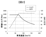
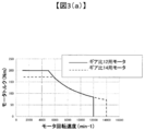
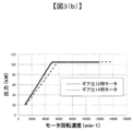
- FIG. 3 shows the required characteristics of the motor when the axle torque is constant.
- a motor having a reduction ratio of 12 has a torque of 12/14 and a maximum rotation speed of 14/12.
- the reduction ratio is increased, the required motor torque is reduced, so that the motor can be miniaturized.
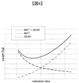
- a reduction gear having a large reduction ratio it is necessary to increase the number of gears or the number of gear stages, so that the reduction gear becomes large. Therefore, as shown in FIG. 4, when considering the entire system, it is necessary to match the physiques of the motor and the speed reducer and design them to be the smallest.
- the capacity of the inverter which is the input power supply to the motor, does not change. In other words, when considering the entire system, it is necessary to design it to be the smallest.
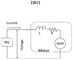
- FIG. 5 is an electric circuit of a general motor.
- the electric circuit of a motor is represented by an internally induced voltage (BEMF), an inductance L, and a resistor R.
- BEMF internally induced voltage
- L inductance
- R resistor
- One of the objects of the present invention is to increase the power factor of a rotary electric machine, and to provide a motor for lowering the inductance L for that purpose. This makes it possible to increase the output density of the drive motor.
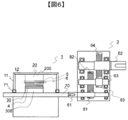
- FIG. 6 is a cross-sectional view of the rotary electric machine 1 and the speed reducer 3 according to the first embodiment.
- the rotary electric machine 1 is composed of a stator 20, a rotor 30, and a housing 12.
- the rotor 30 includes a rotor core 300 and a magnet 4.
- the stator 20 includes a stator core 200, insulating paper 5, and a coil 6.
- the rotor and the stator 20 are housed inside the housing 12.
- the housing 12 includes end brackets 11 at both ends of the rotor in the rotation axis direction.
- the end bracket 11 supports the motor shaft 70 via a bearing 71.
- a rotor 30 is attached to the motor shaft 70. Further, the motor shaft 70 is connected to the input shaft 61 of the speed reducer 3.
- the speed reducer 3 is a two-stage speed reducer.
- the input shaft 61 includes a gear 81.
- the gear 81 is connected to a gear 82 provided on the intermediate shaft 63.
- the output shaft 62 includes a gear 84.
- the ratio of the diameters of the gear 81 and the gear 82 is the reduction ratio of the first stage
- the ratio of the diameters of the gear 83 and the gear 84 is the reduction ratio of the second stage
- this multiplication is the reduction ratio of the speed reducer 3. ..
- the reduction ratio of a two-stage spur gear generally used for automobiles is about 10 to 15.
- FIG. 7 is a perspective view of the stator of the rotary electric machine according to the first embodiment.
- the stator core 200 has a slot 21 for inserting the coil 6.
- the magnetic path of the core is defined as the magnetic path in the radial direction as the tooth portion 22, and the magnetic path in the circumferential direction is defined as the core back 23.
- FIG. 8 is a diagram showing a manufacturing process of a stator winding of a rotary electric machine according to the first embodiment.
- the segment coil 6 is formed in a substantially U shape and is inserted into the slot 21 via the insulator 5.
- the insulator 5 is formed so that the axial length of the rotary electric machine is longer than that of the stator core 200.
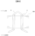
- FIG. 9 is a diagram showing a manufacturing process of a stator winding of a rotary electric machine according to the first embodiment. As shown in FIG. 9, after inserting the segment coils 6 into all the slots 21, each segment coil 6 is bent. This bending process is performed simultaneously for all coils at the same time. After that, adjacent coils are welded to each other.
- the upper part of the paper surface is called the coil mountain side, and the lower part of the paper surface is called the coil welding side.
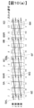
- 10 (a) and 10 (b) are stator winding diagrams of a conventional rotary electric machine.
- the insertion position of the segment coil 6 into the slot 21 and the wiring method are shown.
- the solid line in FIG. 10 is the mountain side of the segment coil 6 in front of the paper surface, and the broken line is the welding side in the back of the paper surface.
- the segment coil 6 is processed so that both ends open in the circumferential direction, and is connected to the adjacent segment coil 6.
- the segment coil 6A is inserted into the stator core 200 from the front of the paper across the second layer of the first slot and the first layer of the fourth slot, and one end of the first slot is bent to the left (6AL), 4 The other end of the No. coil is bent to the right (6AR).
- segment coil 6B is also inserted into the second layer of the 7th slot and the 1st layer of the 10th slot, one end of the 7th slot is bent to the left (6BL), and the other end of the 10th slot is bent to the right. (6BR).
- Coil 6AR and coil 6BL are welded at the intermediate point 7 between the 5th slot and the 6th slot. By repeating this process and making one round of the stator core, a coil is formed by so-called wave winding. This is the series circuit (1) in FIG. 10 (b).
- the coil 6C and the coil 6D are arranged so as to be offset from the connection of the coil 6A and the coil 6B in the radial direction of one coil, and this becomes a series circuit (2).
- the 3rd layer and the 4th layer form a series circuit (3) and a series circuit (4) with the same coil arrangement as the 1st layer and the 2nd layer. Therefore, the number of conductor layers in the slot is inevitably even.
- the number of conductor layers in the slot 21 is NL.
- the stator winding is completed by making these for three phases.
- coils are arranged in the order of + U phase, ⁇ W phase, + V phase, ⁇ U phase, + W phase, and ⁇ V phase in each slot number, and in-phase coils are arranged in each slot. Is placed.
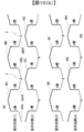
- FIG. 1 is a stator winding diagram of a rotary electric machine according to the first embodiment.
- the U-phase coil is arranged in the first slot and the second slot in the first layer.
- the second layer it is arranged in the second slot and the third slot.
- the third layer it is arranged in the 3rd slot and the 4th slot.
- the fourth layer it is arranged in the 4th slot and the 5th slot.
- Such a winding method in which the slot numbers in which the common-mode coils are inserted are shifted by one is generally called a short-section winding.
- the straddle width of the coil is different between the front side of the paper surface and the other side of the paper surface in FIG.
- the coil 6A is inserted into the second layer of the second slot and the first layer of the seventh slot, and the straddling width thereof is five in terms of the number of slots.
- the coil 6B is inserted into the 14th slot and the 19th slot, and the straddling width thereof is the same as that of the coil 6A, which is the number of slots 5.
- One end of the first layer of the 7th slot of the coil 6A is bent to the right on the other side of the paper surface, and one end of the second layer of the 14th slot of the coil 6B is bent to the left of the paper surface on the other side of the paper surface.
- the coil 6A and the coil 6B are connected by their respective ends. This straddle width is 7 in terms of the number of slots.
- the width on the mountain side of the coil was 3 and the straddling width on the weld side was also 3 and equal.
- the straddling width is different between the mountain side and the welded side.
- the coils of the third and fourth layers are arranged so as to be offset from the first layer and the second layer in the circumferential direction, and the U-phase coil is arranged from the third slot.
- One of the features of the structure of this embodiment is that this Ns is larger than that of the conventional example.
- FIG. 11 shows a conventional coil arrangement.
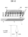
- FIG. 12 is a coil arrangement according to this embodiment.
- the stator coil of the motor receives the magnetic flux of the magnet on the rotor side, which generates torque in the motor.
- the effective utilization rate of the magnetic flux changes depending on the coil arrangement of the motor, and this is called the winding coefficient kW.
- the idea of the winding coefficient kW is 1.0 when all the magnetic fluxes of the one-pole rotor magnet are received.
- the winding coefficient of the U-phase coil for one phase in which these coils are connected in series is the vector sum of the vectors of U1 and U2, respectively.
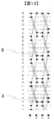
- FIG. 13 is a diagram showing a conventional structure capable of reducing high-order harmonics. Expressed as an equation, it becomes equation (3).
- the inductance L of the motor is calculated by the following equation (4).
- L 1 / P 2 * S rotor / gap * (Nturn * kw 2) ⁇ (4)
- P is the number of poles
- S is the surface area of the gap portion of the rotor
- gap is the distance between the stator core and the rotor core
- NTurn is the number of coil turns per phase
- kw is the winding coefficient.
- the torque Tq of the motor is proportional to the following.
- the torque is proportional to the first power of the winding coefficient and the inductance is proportional to the square. Therefore, if the inductance L of the electric circuit shown in FIG. 5 is small, a larger effective current can be applied to the motor from the same inverter. As a result, the motor of the present embodiment can have a higher output by using the same inverter. In the motor of the present embodiment, the torque of the motor is lower than that of the conventional motor, but the high output still means that the high output is obtained on the higher rotation side.
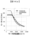
- FIG. 14A is a diagram showing the relationship between the rotational speed of the motor and the torque characteristics.
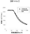
- FIG. 14B is a diagram showing the relationship between the vehicle speed and the axle torque characteristics.
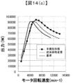
- FIG. 14C is a diagram showing the relationship between the rotation speed of the motor and the output.
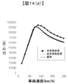
- FIG. 14D is a diagram showing the relationship between the vehicle speed and the output.
- the maximum current and maximum voltage of the inverter are the same, and the maximum speed and low-speed torque on the axle are the same. These are (1) the conventional design (standard) that serves as a reference, (2) the motor physique and maximum speed changed according to the reduction ratio (conventional physique change), and (3) reduced by the coil arrangement of the present embodiment. A comparison is made in which the reduction ratio is increased by the amount of torque (this embodiment).
- the motor when the torque is halved, the motor can drive the rotation speed twice, so the maximum output is the same. In other words, the output does not increase due to the change in physique. Since the motor output is the same, if the axle speed is the same, only the reduction ratio and the motor speed change, but the axle torque does not change.
- FIG. 15 is a diagram showing an example of coil arrangement in this embodiment.
- the relationship of the number of continuous distributions of slots Ns which is a feature of this embodiment, is as follows. NSPP + NL / 2 ⁇ Ns ⁇ 3 * NSPP ... (6) Will be.
- the upper limit of Ns is 3 * NSPP because in a three-phase motor, a coil having a phase difference of 180 ° or more in one phase and a coil having a negative vector sum are generated, and this coil is wasted. Is.
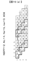
- FIGS. 16 (a), (b) and (c) are diagrams showing an embodiment of the coil arrangement according to the present embodiment.
- the number of slots straddling the mountain side (solid line) in front of the paper surface of the coil is 5, and the straddle on the connecting side across the paper surface is 7.
- the number is 4 on the mountain side and 8 on the connection side.
- FIG. 17 is a diagram showing an embodiment of the coil arrangement according to the present embodiment.
- the winding coefficient is as low as 0.762.
- the winding coefficient kw is smaller than the conventional 0.902.
- the straddle on the mountain side of the coil is 8, and the straddle on the connection side is 10.
- the winding coefficient kw is smaller than the conventional 0.902.
- the straddle on the mountain side of the coil is 8, and the straddle on the connection side is 10.
- the coil connection is almost the same as in FIG. 20A, except that the 3rd and 4th layers and the 7th and 8th layers are deviated by one.
- the winding coefficient kw is smaller than the conventional 0.902.
- the winding coefficient kw is smaller than the conventional 0.925.
- the winding coefficient kw is smaller than the conventional 0.925.
- the winding coefficient kw is smaller than the conventional 0.925.
- FIG. 24 is a diagram showing an embodiment of the coil arrangement according to the first embodiment. This is another example in which the relationship between the straddle on the mountain side of the coil and the straddle on the connection side is "NSPP * 3". Even in such a case, the winding coefficient can be similarly lowered by shifting the coil group consisting of the first and second layers and the coil group consisting of the third and fourth layers in the circumferential direction.
- FIG. 25 (a) and 25 (b) are diagrams showing an embodiment of the coil arrangement according to the first embodiment.
- FIG. 26 is a diagram showing an embodiment of the coil arrangement according to the second embodiment. This is the same as FIG. 24 (a) in the mathematical formula, but the coil arrangement is different.
- FIG. 24A the straddle on the mountain side of all the coils is 9, but in FIG. 25, the straddle of the coils in the third and fourth layers is 8.
- FIGS. 15 to 24 an arrangement in which the coils of each layer have the same width is preferable because the manufacturing tends to be complicated. Specifically, it has a structure in which the straddle on the mountain side and the straddle on the connection side of the same coil as the 1-2 layer are repeated in 2 layers each in the 3-4 layer and the 5-6 layer.
- the structure in which the molded coil is inserted as shown in FIGS. 9 and 10 and then the foot side is bent and welded has been described as an example.
- the molded coil is inserted from both sides.
- the same effect can be obtained by the method of joining inside the core. Further, the same effect can be obtained by the method of connecting both ends of the coil by welding.
- the coil has a rectangular cross-sectional shape as an example, the cross-sectional shape is not limited to this, and the same effect can be obtained even if the cross-sectional shape is, for example, a round shape, a trapezoidal shape, or an elliptical shape.
Landscapes
- Engineering & Computer Science (AREA)
- Power Engineering (AREA)
- Windings For Motors And Generators (AREA)
Abstract
減速機とともに用いるモータにおいて、より高出力を実現する。 本発明に係る回転電機の固定子は、スロットを備える固定子コアと、当該スロット内に挿入される複数のコイルと、を備え、前記スロットは、前記回転電機の径方向に沿って配置された前記複数のコイルのそれぞれによって定義される複数のレイヤを有しており、同相コイルが周方向に連続して並んだ所定数Nsのスロット内に配置され、前記所定数Nsは、毎極毎相スロット数をNSPP、レイヤ数を2×NLとしたとき、NSPP+NL<Ns≦3*NSPPに設定される。
Description
本発明は、回転電機の固定子、回転電機、および車両駆動装置に係り、主に固定子のコイル配置に関する。
昨今の持続可能な社会の実現に向け、回転電機は小型・高効率化が求められている。特に自動車などの移動体向けの回転電機では、コイルの断面を四角にすることで高密度化が図られている。このような回転電機として、例えば特許文献1には、複数の永久磁石を備えた回転子と、この回転子と対向して設けられた固定子鉄心と、固定子鉄心の内周側に開口するように設けられた多数のスロット内に巻掛けられた固定子巻線とを有する永久磁石を備えた回転電機として、U字状に成形された平角断面のセグメントコイルをスロット内に挿入し、溶接で各コイルを結線するモータが示されている。
モータとギアを組合わせたユニットにおいては、モータの回転速度を上げ、ギア比を上げることで出力を一定のまま小型化できる。モータの体格はトルクに比例するため、回転速度を上げれば、その分、トルクが必要なくなるため、小型化できる。ただし、従来の体格変更の設計では、出力そのものは上げられないという課題があった。
上記課題を解決するために、本発明に係る回転電機の固定子は、スロット内に偶数レイヤのコイルが挿入され、コイルは同相コイルが周方向に連続して並んだ所定数Nsのスロット内に配置され、所定数Nsは、毎極毎相スロット数をNSPP、レイヤ数を2×NLとしたとき、NSPP+NL<Ns≦ 3*NSPPに設定される。
本発明によれば、高出力のモータユニットに好適な回転電機を提供することができる。
本発明の目的のひとつは、モータの高出力密度化である。一般にモータの高出力化と小型化は同じ意味で用いられることが多いが、正確には高出力密度化が重要となる。出力密度が高いということは、同じ出力ならば小型にでき、同じ体格から多くの出力が得られる。
モータの出力は「トルク×回転速度」である。すなわち、モータの出力向上のためには、トルクを向上させるか、モータの回転速度を向上する必要がある。ここで、一般にモータのトルクはモータの体格に比例する。また、トルク密度(単位体積あたりの電磁力)は、電流密度とコアの磁束密度とで決まり、これらは適用される材料の物性で決まる。そのため、トルク密度を上げるには、コイルとコアの実装密度を上げることでしか実現できない。
ここで、一般に駆動モータは減速機を介して車軸にトルクを伝達するため、モータと減速機の合計の体積を小さくしなければならない。図3は、車軸トルクを一定にした場合のモータへの要求特性である。減速比12のモータに比べ、減速比14のモータは、トルクは12/14、最大回転速度は14/12になる。このように、減速比を大きくすれば必要とされるモータトルクが下がるため、モータを小型化できる。一方、減速比が大きい減速機は歯車を大きくするか、ギアの段数を増やす必要があるため、減速機が大型化してしまう。このため、図4に示されるように、システム全体で考えた場合、モータと減速機の体格を合わせて、最も小型に設計する必要がある。
車軸で要求される速度とトルクが同じ、つまり車軸出力が同じであれば、モータとして求められる出力は同じである。これを電源側からみると、モータへの入力電源であるインバータの容量は変わらない。つまり、システム全体で考えた場合に、最も小型に設計する必要がある。
次に、本発明のもとになる原理を説明する。図5は、一般的なモータの電気回路である。図5に示されるように、モータの電気回路は、内部誘起電圧(BEMF)とインダクタンスLと抵抗Rとで表される。インバータ(INV)の容量制約である最大電流と最大電圧とをそれぞれImax、Vmaxとすると、インバータの最大皮相電力KVAは以下の(1)式であらわされる。
KVA=√3×Imax×Vmax ・・・・(1)
ここで、効率をEFF、力率をcosθとすると、モータの最大出力Pmaxは(2)式で表される。
ここで、効率をEFF、力率をcosθとすると、モータの最大出力Pmaxは(2)式で表される。
Pmax=KVA×cosθ×EFF ・・・・(2)
つまり、回転電機の力率、または、効率を上げれば、同じ電力で出力を上げることができる。本発明の目的のひとつは、回転電機の力率を上げることにあり、そのためにインダクタンスLを下げるモータを提供することにある。これにより、駆動用モータの高出力密度化を可能にする。
つまり、回転電機の力率、または、効率を上げれば、同じ電力で出力を上げることができる。本発明の目的のひとつは、回転電機の力率を上げることにあり、そのためにインダクタンスLを下げるモータを提供することにある。これにより、駆動用モータの高出力密度化を可能にする。
[実施形態1] 本発明に係る第1の実施形態を図6を用いて説明する。図6は、第1実施形態に係る回転電機1と減速機3の断面図である。図6に示されるように、回転電機1は、固定子20と回転子30とハウジング12とにより構成される。回転子30は、回転子鉄心300と磁石4とからなる。固定子20は、固定子鉄心200、絶縁紙5及びコイル6を備える。
回転子と固定子20は、ハウジング12の内部に収納される。ハウジング12は、回転子の回転軸方向の両端にエンドブラケット11を備える。エンドブラケット11は、ベアリング71を介してモータシャフト70を支えている。モータシャフト70には回転子30が取り付けられている。また、モータシャフト70は、減速機3の入力軸61と接続されている。
回転子と固定子20は、ハウジング12の内部に収納される。ハウジング12は、回転子の回転軸方向の両端にエンドブラケット11を備える。エンドブラケット11は、ベアリング71を介してモータシャフト70を支えている。モータシャフト70には回転子30が取り付けられている。また、モータシャフト70は、減速機3の入力軸61と接続されている。
本実施形態において、減速機3は2段減速機である。入力軸61は、歯車81を備える。歯車81は、中間軸63に備えられる歯車82と接続される。出力軸62は、歯車84を備えている。ここで、歯車81と歯車82の径の比が1段目の減速比、歯車83と歯車84の径の比が二段目の減速比であり、この掛け算が減速機3の減速比となる。一般に、減速比を大きくするためには歯車82や84を大径化する必要がある。したがって、大型化を避けるためには極端な減速比は取れない。一般に自動車用として用いられる二段平歯車の減速比は10~15程度である。
図7は、第1の実施形態に係る回転電機の固定子の斜視図である。図7に示されるように、固定子鉄心200は、コイル6を挿入するためのスロット21を有する。ここで、コアの磁路を径方向の磁路をティース部22と周方向の磁路であるコアバック23と定義する。
図8は、第1の実施形態に係る回転電機の固定子巻線の製造工程を示す図である。図8に示されるように、セグメントコイル6は、略U字状に形成され、絶縁体5を介してスロット21に挿入される。絶縁体5は、回転電機の軸方向の長さが、固定子鉄心200より長く形成されている。
図9は、第1の実施形態に係る回転電機の固定子巻線の製造工程を示す図である。図9に示されるように、すべてのスロット21にセグメントコイル6を挿入後、各セグメントコイル6の曲げ加工を行う。この曲げ加工は、すべてのコイルで一斉に同時に行う。その後、隣接するコイル同士を溶接する。ここで、紙面上方をコイル山側、紙面下方をコイル溶接側と呼ぶ。
図10(a)及び図10(b)は従来の回転電機の固定子巻線図である。セグメントコイル6のスロット21への挿入位置と結線方法とが示されている。ここでは、3相交流の1相分のセグメントコイル6だけを示す。図10の実線が紙面手前でセグメントコイル6の山側、破線は紙面奥の溶接側である。
セグメントコイル6は、スロット21挿入後に両端を周方向に開くように加工され、隣のセグメントコイル6と接続される。たとえば、セグメントコイル6Aが1番スロットの2層目と4番スロットの1層目に跨って紙面手前から固定子鉄心200に差し込まれ、1番スロットの一端は左側に曲げられ(6AL)、4番コイルの他端は右側(6AR)に曲げられる。
セグメントコイル6Bも同様に、7番スロットの2層目と10番スロットの1層目に差し込まれ、7番スロットの一端は左に曲げられ(6BL)、10番スロットの他端は右に曲げられる(6BR)。
コイル6ARとコイル6BLは、5番スロットと6番スロットとの間の中間地点7で溶接される。この工程が繰り返され、固定子コアを1周することで、いわゆる波巻きによりコイルが形成される。これが図10(b)における直列回路(1)である。
コイル6C及びコイル6Dは、コイル6A及びコイル6Bの接続とコイルひとつ分径方向にずれて配置され、これが直列回路(2)となる。図10では、3層及び4層は、1層及び2層と同じコイル配置で、直列回路(3)と直列回路(4)を形成する。したがって、スロット内の導体層数は必然的に偶数になる。ここで、このスロット21内導体層数をNLとする。これらを3相分作ることで固定子巻線が完成する。
図10に示される従来例では、各スロット番号それぞれに+U相、-W相、+V相、-U相、+W相、-V相という順でコイルが配置されており、各スロットには同相コイルが配置されている。
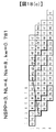
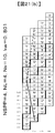
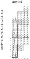
図1は、第1の実施形態に係る回転電機の固定子巻線図である。図10に示される従来例と比較すると、本実施形態においては、各相コイルが1層ごとに周方向に2つずつ配置されている。これは一般に毎極毎相スロット数と呼ばれ、ここではNSPP=2と表される。図10で示された従来例はNSPP=1である。
図1において、U相コイルは、第1層においては1番スロット及び2番スロットに配置される。第2層においては2番スロット及び3番スロットに配置される。第3層においては3番スロット及び4番スロットに配置される。第4層においては4番スロット及び5番スロットに配置される。このように同相コイルの挿入されているスロット番号が1つずれている巻き方は一般的には短節巻と呼ばれる。本実施形態では、U相のコイルは第1から第5スロットまで連続したスロットに挿入されており、これをスロット連続分布数Ns=5と表すことにする。
また、図1の紙面手前と紙面向こう側では、コイルの跨り幅も異なる。コイル6Aは、2番スロット第2層と7番スロット第1層に差し込まれ、その跨り幅はスロット数で5である。コイル6Bは14番スロットと19番スロットに差し込まれ、その跨り幅はコイル6Aと同様にスロット数5である。コイル6Aの7番スロット第1層の一端は紙面向こう側で右方に曲げられ、コイル6Bの14番スロット第2層の一端は紙面向こう側で紙面左方に曲げられる。コイル6Aとコイル6Bはそれぞれの端部により接続される。この跨り幅はスロット数で7となる。
回転電機として1極分の幅はスロット数6を基準とすると、コイル6A、6Bの山側の幅は6-1=5、溶接側の跨り幅は6+1=7となる。従来の図10の例では、コイルの山側の幅は3、溶接側跨り幅も3で等しかった。本実施形態では山側と溶接側とで跨り幅が異なっている。また、第3及び第4層目のコイルは第1層、第2層と周方向にずれて配置されており、3番スロットからU相コイルを配置している。
これらの状態を上記で定義した記号を用いて表現すると、図1のコイル配置は、NL=4、NSPP=2、Ns=5である。一方、図10のコイル配置は、NL=4、NSPP=2、Ns=2の配置である。このNsが従来例と比べると大きいことが本実施形態の構造の特徴のひとつである。
このようなセグメントコイルの配置をすることの作用を図11及び図12を用いて説明する。図11は従来のコイル配置を示す。、図12は本実施形態に係るコイル配置である。
図11において、従来のコイル配置は、NL=4、NSPP=2、Ns=2である。一方で、本実施形態のコイル配置はNLとNSPPは従来構造と同じだあるが、Ns=5である点が異なる。
図11において、従来のコイル配置は、NL=4、NSPP=2、Ns=2である。一方で、本実施形態のコイル配置はNLとNSPPは従来構造と同じだあるが、Ns=5である点が異なる。
モータの固定子コイルは回転子側の磁石磁束を受け、それによりモータにトルクが発生する。このとき、モータのコイル配置によって磁束の有効利用率が変わり、これを巻線係数kwという。巻線係数kwの考え方は1極の回転子磁石の磁束をすべて受ければ1.0となるものである。図11に示される従来のコイル配置の場合、コイルをU1とU2に分けると、この2つのグループは回転子から見て位相が異なる。そのため、これらのコイルを直列につないだ1相分のU相コイルの巻線係数は、U1とU2のそれぞれのベクトルのベクトル和となる。NSPP=2の3相モータの固定子の場合、モータの電気角1周期は、1周期12スロットである。スロット1つ分の電気角は30度、U1とU2コイルの位相差は30度であるため、その合計平均は、cos(15°)=0.966となる。
一方、図12に示される本実施形態の構造では、U3コイルを中心にして、U2とU4コイルは30°位相がずれており、U1とU5コイルは60°ずれている。したがって、巻線係数kwは、{2*cos(0°)+4*cos(30°)+2*cos(0°)}/8=0.808となる。
巻線係数kwが低下するとモータのトルクも低下するため、通常好ましくないとされる。そのため、通常はこのような構造は採用されない。しかし、高次の次数に対する巻線係数の低下に対応しなければならないときは、限定的ではあるがそのような構成が採用される場合もある。たとえば図13は高次高調波を低減できる従来の構造を示した図である。
式として表すと(3)式となる。
式として表すと(3)式となる。
NSPP+NL/2=Ns ・・・・・・(3)
この場合の巻線係数を考えると、2番3番スロットの中心がU相コイルの中心だから、2番と3番スロットはそれぞれ±15°、1番と4番スロットはそれぞれ±45°中心からずれているため、巻線係数kwは以下になる。
この場合の巻線係数を考えると、2番3番スロットの中心がU相コイルの中心だから、2番と3番スロットはそれぞれ±15°、1番と4番スロットはそれぞれ±45°中心からずれているため、巻線係数kwは以下になる。
{6*cos(15°)+2*cos(45°)}/8=0.901
しかし、とくに自動車用モータのように高出力密度が求められるモータにおいて、巻線係数は少しでも高い方が望ましいため、図1のような巻線をあえて採用することはなかった。たとえば、図11のNSPP=2の場合、通常、コイル跨ぎスロット数5/6の短節巻で高調波が下がるため、その場合の巻線係数0.933よりも低い巻線をすることは無い。
しかし、とくに自動車用モータのように高出力密度が求められるモータにおいて、巻線係数は少しでも高い方が望ましいため、図1のような巻線をあえて採用することはなかった。たとえば、図11のNSPP=2の場合、通常、コイル跨ぎスロット数5/6の短節巻で高調波が下がるため、その場合の巻線係数0.933よりも低い巻線をすることは無い。
本実施形態では、あえて巻線係数kwを低くする方法を取っている。それは、図5で示されるモータのインダクタンスを低減するためである。
モータのインダクタンスLは以下の式(4)で求められる。
L=1/P2*Srotor/gap*(Nturn*kw2) ・・・(4)
ここで、Pは極数、Sは回転子のギャップ部表面積、gapは固定子鉄心と回転子鉄心の距離、Nturnは1相当たりのコイル巻数、kwは巻線係数である。
一方、モータのトルクTqは以下に比例する。
L=1/P2*Srotor/gap*(Nturn*kw2) ・・・(4)
ここで、Pは極数、Sは回転子のギャップ部表面積、gapは固定子鉄心と回転子鉄心の距離、Nturnは1相当たりのコイル巻数、kwは巻線係数である。
一方、モータのトルクTqは以下に比例する。
Tq∝Srotor*I*(Nturn*kw)∝BEMF ・・・(5)
ここで、Iはモータ電流である。
ここで、Iはモータ電流である。
これらの式から、トルクは巻線係数の1乗に比例し、インダクタンスは2乗比例することが分かる。したがって、図5に示される電気回路のインダクタンスLが小さいならば、同じインバータからより大きな有効電流をモータに与えることができる。これにより本実施形態のモータは、同じインバータを用いてより高出力化できる。本実施形態のモータは、従来よりもモータのトルクは下がるが、それでも高出力ということは、より高回転側で高出力になるということである。
図14(a)は、モータの回転速度とトルク特性との関係を示した図である。図14(b)は、車両速度と車軸トルク特性との関係を示した図である。図14(c)は、モータの回転速度と出力との関係を示した図である。図14(d)は、車両速度と出力との関係を示した図である。インバータの最大電流と最大電圧が同一、車軸での最大速度と低速トルクが同等の条件でる。それぞれ(1)基準となる従来の設計(基準)、(2)減速比に応じてモータの体格と最高速度を変更したもの(従来体格変更)、(3)本実施形態のコイル配置により減ったトルク分だけ減速比を増加させたもの(本実施形態)を比較している。
図14(a)及び(b)に示されるように、モータでのトルク特性は3つとも異なるが、車軸でのトルク特性は、本実施形態は高速側で増加していることが分かる。
図14(c)及び(d)に示されるように、モータ回転速度に対する出力特性は異なるが、車両速度に対する出力特性は本実施形態でのみ増えることが分かる。
ここで、(4)式と(3)式から、従来の体格変更でトルクを小さくして小型化した場合を考える。所要トルクが半分になると、モータの磁気回路の軸長を半分にすることができる。それは上式ではSrotorを半分にできることになる。この場合、インダクタンスもトルクも半分になる。一方、誘起電圧BEMFも半分、コイルの抵抗も略半分になる。最大電流は変わらないため、同じ回転速度で電圧が半分になり、回転速度が2倍で同じ電圧になる。
つまり、モータはトルクが半分になると、回転速度を2倍で駆動できるので最大出力は等しい。つまり、体格変更で出力は増えない。モータ出力が同じなので、車軸速度が同じであれば、減速比とモータの速度が変わるだけで、車軸トルクは変わらない。これらのことは、図3に示される、減速比の変更に応じてモータ体格を変更した場合のモータのトルク、出力特性の変化の説明である。
このように、本実施形態では従来の設計変更で実現できなかった車軸での高出力化が可能となる。
図15は、本実施形態におけるコイル配置の例を示した図である。モータ固定子のコイルの層数がNL、毎極毎相スロット数がNSPPの場合、本実施形態の特徴であるスロット連続分布数Nsの関係は、
NSPP+NL/2<Ns≦3*NSPP ・・・(6)
となる。
NSPP+NL/2<Ns≦3*NSPP ・・・(6)
となる。
ここで、Nsの上限が3*NSPPであるのは、3相モータでは1相内で位相が180°以上異なるコイルと、ベクトルの和がマイナスのコイルが発生し、このコイルが無駄となるためである。
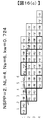
図16(a)、(b)及び(c)は、本実施形態に係るコイル配置の一実施例を示した図である。毎極毎相スロット数NSPP=2、コイルの層数NL=2の場合を示している。また(6)式によればNsの上限値は6なので、その例を図16(b)と図16(c)に示す。
図16(a)及び(b)に示された例では、コイルの紙面手前の山側(実線)の跨りはスロット数で5、紙面向こう側の亘りの接続側で7である。図16(c)では、山側4、接続側で8である。どの実施例においても、巻線係数kwはは、従来用いられるNSPP=2、コイル跨ぎスロット数5/6の巻線係数0.933よりも小さい。
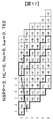
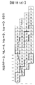
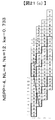
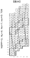
図17は、本実施形態に係るコイル配置の一実施例を示した図である。NSPP=2、NL=6、Ns=6の場合であり、コイルの山側の跨りは5、溶接側の亘りは7である。
巻線係数は0.762と低い。
巻線係数は0.762と低い。
図18から図20はNSPP=3の場合のコイル配置の一実施例を示した図である。NSPP=3のコイル配置は、従来例の場合、高調波を下げるためにコイル跨ぎスロット数7/9で用いられることが多く、その巻線係数は0.902である。
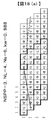
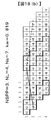
図18は、NSPP=3、NL=4の場合のコイル配置の一実施例を示した図である。
図18(a)はNs=6、コイルの山側の跨りは8、接続側の亘りは10となっている。
図18(b)はNs=7で、コイルの接続は図18(a)とほぼ同様だが、1及び2層目のコイル群が3及び4層目のコイル群と周方向に一つずれているところが異なる。図18(c)はNs=8で、コイルの山側の跨りは7、接続側の亘りは11となっている。図18(d)はNs=9の場合で、図18(c)と同様だが、3、4層目の位置がずれている。巻線係数kwはいずれも従来の0.902より小さい。
図18(a)はNs=6、コイルの山側の跨りは8、接続側の亘りは10となっている。
図18(b)はNs=7で、コイルの接続は図18(a)とほぼ同様だが、1及び2層目のコイル群が3及び4層目のコイル群と周方向に一つずれているところが異なる。図18(c)はNs=8で、コイルの山側の跨りは7、接続側の亘りは11となっている。図18(d)はNs=9の場合で、図18(c)と同様だが、3、4層目の位置がずれている。巻線係数kwはいずれも従来の0.902より小さい。
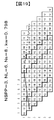
図19は、NSPP=3、NL=4、Ns=8の場合のコイル配置の一実施例を示した図である。コイルの山側の跨りは8、接続側の亘りは10となっている。巻線係数kwはいずれも従来の0.902より小さい。
図20(a)及び(b)は、NSPP=3、NL=8の場合のコイル配置の一実施例を示した図である。図20(a)はNs=8である。コイルの山側の跨りは8、接続側の亘りは10となっている。図20(b)はNs=9である。コイルの接続は図20(a)とほぼ同様だが、3、4層目と7、8層目が一つずれているところが異なる。巻線係数kwはいずれも従来の0.902より小さい。
図21から図23はNSPP=4の場合のコイル配置の一実施例を示した図である。NSPP=4のコイル配置は、従来例の場合、高調波を下げるためにコイル跨ぎスロット数10/12で用いられることが多く、その巻線係数は0.925である。
図21(a)(b)、および(c)は、NSPP=4、NL=4の場合コイル配置の一実施例を示した図である。図21(a)はNs=7、コイルの山側の跨りは11、接続側の亘りは13となっている。図21(b)はNs=10、コイルの山側の跨りは10、接続側の亘りは14となっている。図21(c)はNs=12、コイルの山側の跨りは9、接続側の亘りは15となっている。巻線係数kwはいずれも従来の0.925より小さい。
図22は、NSPP=4、NL=6、Ns=9の場合であり、コイルの山側の跨りは11、接続側の亘りは13となっている。巻線係数kwは従来の0.925より小さい。
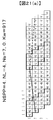
図23は、NSPP=4、NL=8、Ns=9の場合であり、コイルの山側の跨りは11、接続側の亘りは13となっている。巻線係数kwは従来の0.925より小さい。
以上の実施例では、コイルの山側の跨りと接続側の亘りの関係が「NSPP*3±n(nは自然数)」となることが分かる。ここで3は三相モータであるためである。
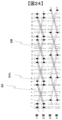
図24は、第1の実施形態に係るコイル配置の一実施例を示した図である。コイルの山側の跨りと接続側の亘りの関係が「NSPP*3」である別の例である。このような場合でも1及び2層目からなるコイル群と3及び4層目からなるコイル群とを周方向にずらすことで同様に巻線係数を下げることができる。
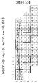
図25(a)及び図25(b)は、第1の実施形態に係るコイル配置の一実施例を示した図である。図25(a)はNSPP=3、NL=6、Ns=7の場合、図25(b)はNSPP=3、NL=6、Ns=9の場合である。巻線係数kwはいずれも従来のNSPP=3の短節巻のkw0.902より小さい。
図26は、第2の実施形態に係るコイル配置の一実施例を示した図である。これは数式上では図24(a)と同じだが、コイル配置が異なる。図24(a)はすべてのコイルの山側の跨りは9であるが、図25では3、4層目のコイルの跨りは8である。ただし、制作時に違う跨り幅に成形したコイルを用意する必要がある。さらに、図9のように接続側を曲げる際に、1、2、5、6層目と、3、4層目で違う長さに曲げなければならない。
したがって、製造が複雑になりやすいため、図15から図24に示されるように、各層のコイルが同じ幅になるような配列が好ましい。具体的には、1-2層と同じコイルの山側の跨りと接続側の亘りを、3-4層や5-6層に2層ずつ繰り返す構造である。
したがって、製造が複雑になりやすいため、図15から図24に示されるように、各層のコイルが同じ幅になるような配列が好ましい。具体的には、1-2層と同じコイルの山側の跨りと接続側の亘りを、3-4層や5-6層に2層ずつ繰り返す構造である。
なお、図9、図10に示されるように成形したコイルを差し込んだあと、足側を曲げて溶接する構造を例に説明したが、図27に示されるように、成形したコイルを両側から差し込み、コアの内部で接合する方法などにおいても同様の効果が得られる。また、コイルの両端を溶接により接続する方法においても同様の効果が得られる。また、コイルは断面形状が矩形のものを例に示したが、断面形状はこれに限定されず、例えば、丸形、台形、楕円形等の断面形状であっても同様の効果が得られる。
1…回転電機、4…永久磁石、3…減速機、5…絶縁紙、6…コイル、7…溶接点、11…エンドブラケット、12…ハウジング、20…固定子、21…スロット、22…ティース、23…コアバック、30…回転子、61…入力軸、62…出力軸、63…中間軸、70…モータシャフト、71…ベアリング、81…第一歯車、82…第二歯車、83…第三歯車、84…第四歯車、200…固定子鉄心、300…回転子鉄心
Claims (9)
- スロットを備える固定子コアと、
当該スロット内に挿入される複数のコイルと、を備える回転電機の固定子であって、
前記スロットは、前記回転電機の径方向に沿って配置された前記複数のコイルのそれぞれによって定義される複数のを有しており、
同相コイルが周方向に連続して並んだ所定数Nsのスロット内に配置され、
前記所定数Nsは、毎極毎相スロット数をNSPP、レイヤ数を2×NLとしたとき、
NSPP+NL<Ns≦3*NSPPに設定される回転電機の固定子。 - 請求項1に記載の回転電機の固定子であって、
前記複数のコイルは、前記固定子コアの両側においてスロットピッチがNSPP*3となるように配置される回転電機の固定子。 - 請求項1に記載の回転電機の固定子であって、
nを自然数とすると、
前記複数のコイルは、前記固定子コアの軸方向の一方側において、
スロットピッチがNSPP*3+nとなるように配置され、
前記固定子コアの軸方向の他方側において、スロットピッチがNSPP*3-nとなるように配置される
回転電機の固定子。 - 請求項1乃至3のいずれかひとつに記載の回転電機の固定子であって、
nを自然数としたときに、
第2nレイヤに配置される第1コイルと前記第1コイルと同相であって第2n+1レイヤに配置されるコイルとが、同スロット内に配置される
回転電機の固定子。 - 請求項1乃至3のいずれかひとつに記載の回転電機の固定子であって、
nを自然数としたときに、
第2n-1レイヤに配置される第1コイルと第2nレイヤに配置される前記第1コイルと同相である第2コイルとからなる第1コイル群と、
第2n+1レイヤに配置される前記第1コイルと同相である第3コイルと第2n+2レイヤに配置される前記第1コイルと同相である第4コイルとからなる第2コイル群と、を備え、
前記第1コイル群と前記第2コイル群とは、周方向に1以上ずれて配置される回転電機の固定子。 - 請求項1乃至5のいずれかひとつに記載の回転電機の固定子であって、
前記コイルは、矩形断面の形状を有しており、略U字状に形成され、
前記固定子コアの一方側から挿入され、他方側において他のコイルと接続される回転電機の固定子。 - 請求項1乃至5のいずれかひとつに記載の回転電機の固定子であって、
前記コイルは、矩形断面の形状を有しており、略U字状に形成され、
前記固定子コアの一方側から挿入され、前記スロット内において他のコイルと接続される回転電機の固定子。 - 請求項1乃至7のいずれかひとつに記載の回転電機の固定子と、
前記固定子に対して所定の空隙を介して対向する回転子と、を備える回転電機。 - 請求項8に記載の回転電機と、当該回転電機に所定の周波数の交流電力を供給する電力変換器と、前記回転電機の出力軸に減速機と、を備える車両駆動装置。
Priority Applications (1)
| Application Number | Priority Date | Filing Date | Title |
|---|---|---|---|
| DE112020006611.8T DE112020006611T5 (de) | 2020-03-09 | 2020-12-25 | Stator einer rotierenden elektrischen maschine, rotierende elektrische maschine und fahrzeugantriebsvorrichtung |
Applications Claiming Priority (2)
| Application Number | Priority Date | Filing Date | Title |
|---|---|---|---|
| JP2020039515A JP7288414B2 (ja) | 2020-03-09 | 2020-03-09 | 回転電機の固定子、回転電機、および車両駆動装置 |
| JP2020-039515 | 2020-03-09 |
Publications (1)
| Publication Number | Publication Date |
|---|---|
| WO2021181824A1 true WO2021181824A1 (ja) | 2021-09-16 |
Family
ID=77669234
Family Applications (1)
| Application Number | Title | Priority Date | Filing Date |
|---|---|---|---|
| PCT/JP2020/048696 Ceased WO2021181824A1 (ja) | 2020-03-09 | 2020-12-25 | 回転電機の固定子、回転電機、および車両駆動装置 |
Country Status (3)
| Country | Link |
|---|---|
| JP (1) | JP7288414B2 (ja) |
| DE (1) | DE112020006611T5 (ja) |
| WO (1) | WO2021181824A1 (ja) |
Cited By (1)
| Publication number | Priority date | Publication date | Assignee | Title |
|---|---|---|---|---|
| CN115411860A (zh) * | 2022-08-12 | 2022-11-29 | 华为数字能源技术有限公司 | 定子、扁线电机、动力总成和车辆 |
Families Citing this family (1)
| Publication number | Priority date | Publication date | Assignee | Title |
|---|---|---|---|---|
| JP7687265B2 (ja) | 2022-04-21 | 2025-06-03 | 株式会社アイシン | 回転電機用ステータ |
Citations (4)
| Publication number | Priority date | Publication date | Assignee | Title |
|---|---|---|---|---|
| WO2010103634A1 (ja) * | 2009-03-11 | 2010-09-16 | 株式会社 日立製作所 | 車両用交流発電機 |
| WO2012053304A1 (ja) * | 2010-10-19 | 2012-04-26 | 日産自動車株式会社 | 回転電機及び車載回転電機システム |
| JP2014096985A (ja) * | 2014-01-23 | 2014-05-22 | Toyota Industries Corp | 回転電機の固定子 |
| WO2018002609A1 (en) * | 2016-06-29 | 2018-01-04 | Cummins Generator Technologies Limited | Auxiliary windings in a rotating electrical machine |
Family Cites Families (1)
| Publication number | Priority date | Publication date | Assignee | Title |
|---|---|---|---|---|
| JP5792363B2 (ja) | 2014-07-24 | 2015-10-07 | 日立オートモティブシステムズ株式会社 | 回転電機の固定子巻線、および回転電機の固定子 |
-
2020
- 2020-03-09 JP JP2020039515A patent/JP7288414B2/ja active Active
- 2020-12-25 DE DE112020006611.8T patent/DE112020006611T5/de active Pending
- 2020-12-25 WO PCT/JP2020/048696 patent/WO2021181824A1/ja not_active Ceased
Patent Citations (4)
| Publication number | Priority date | Publication date | Assignee | Title |
|---|---|---|---|---|
| WO2010103634A1 (ja) * | 2009-03-11 | 2010-09-16 | 株式会社 日立製作所 | 車両用交流発電機 |
| WO2012053304A1 (ja) * | 2010-10-19 | 2012-04-26 | 日産自動車株式会社 | 回転電機及び車載回転電機システム |
| JP2014096985A (ja) * | 2014-01-23 | 2014-05-22 | Toyota Industries Corp | 回転電機の固定子 |
| WO2018002609A1 (en) * | 2016-06-29 | 2018-01-04 | Cummins Generator Technologies Limited | Auxiliary windings in a rotating electrical machine |
Cited By (1)
| Publication number | Priority date | Publication date | Assignee | Title |
|---|---|---|---|---|
| CN115411860A (zh) * | 2022-08-12 | 2022-11-29 | 华为数字能源技术有限公司 | 定子、扁线电机、动力总成和车辆 |
Also Published As
| Publication number | Publication date |
|---|---|
| DE112020006611T5 (de) | 2022-11-10 |
| JP7288414B2 (ja) | 2023-06-07 |
| JP2021141774A (ja) | 2021-09-16 |
Similar Documents
| Publication | Publication Date | Title |
|---|---|---|
| KR101115641B1 (ko) | 고효율 영구 자석 브러시리스 모터 | |
| US6815859B2 (en) | Synchronous reluctance motor | |
| US6998750B2 (en) | Permanent magnet type three-phase AC rotary electric machine | |
| US7143503B2 (en) | Brushless permanent magnet machine with axial modules of rotor magnetization skew and method of producing the same | |
| CN101189782B (zh) | 电动机及其控制装置 | |
| EP2224578A1 (en) | Stator winding scheme of a permanent magnet machine | |
| JP5620759B2 (ja) | 電気機械 | |
| KR101165184B1 (ko) | 회전 전기기계 | |
| EP2180580A2 (en) | Motor | |
| CN1030854A (zh) | 可控变速感应电动机 | |
| JP7365983B2 (ja) | 固定子及び回転電機、並びに電動ホイール及び車両 | |
| JPWO2008044703A1 (ja) | 回転電機の固定子およびその固定子の製造方法並びに回転電機の製造方法 | |
| US10916981B2 (en) | Permanent magnet rotating device having minimized cogging torque, permanent magnet generator using same, and permanent magnet motor | |
| US20210305868A1 (en) | Rotary electric machine | |
| JPWO2020178953A1 (ja) | 発電電動機およびその製造方法 | |
| JP3535485B2 (ja) | 3相ハイブリッド形ステッピングモータ | |
| JP6819211B2 (ja) | 回転電機 | |
| KR20200010493A (ko) | 회전 전기 기계 및 직동 전동기 | |
| EP1244195A1 (en) | Winding scheme for a permanent magnet type three-phase ac rotary electric machine | |
| JP2021141774A (ja) | 回転電機の固定子、回転電機、および車両駆動装置 | |
| JP2912277B2 (ja) | 永久磁石を有し広い速度範囲に亘って一定電力で作動するようにされた同期電気機械 | |
| US7247964B2 (en) | Electrical machine with magnetized rotor | |
| US20080290754A1 (en) | AC Motor | |
| JP4114570B2 (ja) | 回転電機用電機子 | |
| JP2017184475A (ja) | モータ装置、およびモータ装置の製造方法 |
Legal Events
| Date | Code | Title | Description |
|---|---|---|---|
| 121 | Ep: the epo has been informed by wipo that ep was designated in this application |
Ref document number: 20924416 Country of ref document: EP Kind code of ref document: A1 |
|
| 122 | Ep: pct application non-entry in european phase |
Ref document number: 20924416 Country of ref document: EP Kind code of ref document: A1 |