EP2224578A1 - Stator winding scheme of a permanent magnet machine - Google Patents
Stator winding scheme of a permanent magnet machine Download PDFInfo
- Publication number
- EP2224578A1 EP2224578A1 EP09153981A EP09153981A EP2224578A1 EP 2224578 A1 EP2224578 A1 EP 2224578A1 EP 09153981 A EP09153981 A EP 09153981A EP 09153981 A EP09153981 A EP 09153981A EP 2224578 A1 EP2224578 A1 EP 2224578A1
- Authority
- EP
- European Patent Office
- Prior art keywords
- span
- coil
- permanent magnet
- stator
- magnet machine
- Prior art date
- Legal status (The legal status is an assumption and is not a legal conclusion. Google has not performed a legal analysis and makes no representation as to the accuracy of the status listed.)
- Withdrawn
Links
- 238000004804 winding Methods 0.000 title claims abstract description 116
- 238000000034 method Methods 0.000 claims abstract description 18
- 239000004020 conductor Substances 0.000 claims description 2
- 238000013461 design Methods 0.000 description 70
- 239000011295 pitch Substances 0.000 description 28
- 230000001788 irregular Effects 0.000 description 19
- 230000008901 benefit Effects 0.000 description 8
- 238000013459 approach Methods 0.000 description 5
- 230000014509 gene expression Effects 0.000 description 4
- 239000000463 material Substances 0.000 description 4
- 230000002349 favourable effect Effects 0.000 description 3
- 230000004907 flux Effects 0.000 description 3
- 239000010410 layer Substances 0.000 description 3
- RYGMFSIKBFXOCR-UHFFFAOYSA-N Copper Chemical compound [Cu] RYGMFSIKBFXOCR-UHFFFAOYSA-N 0.000 description 2
- 229910052802 copper Inorganic materials 0.000 description 2
- 239000010949 copper Substances 0.000 description 2
- 238000006073 displacement reaction Methods 0.000 description 2
- 238000005516 engineering process Methods 0.000 description 2
- 239000002356 single layer Substances 0.000 description 2
- 238000005352 clarification Methods 0.000 description 1
- 238000001125 extrusion Methods 0.000 description 1
- 238000003780 insertion Methods 0.000 description 1
- 230000037431 insertion Effects 0.000 description 1
- 238000004519 manufacturing process Methods 0.000 description 1
- 238000010248 power generation Methods 0.000 description 1
- 210000003813 thumb Anatomy 0.000 description 1
- 238000012795 verification Methods 0.000 description 1
Images


Classifications
-
- H—ELECTRICITY
- H02—GENERATION; CONVERSION OR DISTRIBUTION OF ELECTRIC POWER
- H02K—DYNAMO-ELECTRIC MACHINES
- H02K3/00—Details of windings
- H02K3/04—Windings characterised by the conductor shape, form or construction, e.g. with bar conductors
- H02K3/28—Layout of windings or of connections between windings
-
- H—ELECTRICITY
- H02—GENERATION; CONVERSION OR DISTRIBUTION OF ELECTRIC POWER
- H02K—DYNAMO-ELECTRIC MACHINES
- H02K1/00—Details of the magnetic circuit
- H02K1/06—Details of the magnetic circuit characterised by the shape, form or construction
- H02K1/12—Stationary parts of the magnetic circuit
- H02K1/14—Stator cores with salient poles
- H02K1/145—Stator cores with salient poles having an annular coil, e.g. of the claw-pole type
-
- H—ELECTRICITY
- H02—GENERATION; CONVERSION OR DISTRIBUTION OF ELECTRIC POWER
- H02K—DYNAMO-ELECTRIC MACHINES
- H02K1/00—Details of the magnetic circuit
- H02K1/06—Details of the magnetic circuit characterised by the shape, form or construction
- H02K1/22—Rotating parts of the magnetic circuit
- H02K1/27—Rotor cores with permanent magnets
- H02K1/2706—Inner rotors
-
- H—ELECTRICITY
- H02—GENERATION; CONVERSION OR DISTRIBUTION OF ELECTRIC POWER
- H02K—DYNAMO-ELECTRIC MACHINES
- H02K15/00—Methods or apparatus specially adapted for manufacturing, assembling, maintaining or repairing of dynamo-electric machines
- H02K15/04—Methods or apparatus specially adapted for manufacturing, assembling, maintaining or repairing of dynamo-electric machines of windings, prior to mounting into machines
- H02K15/0435—Wound windings
Definitions
- the invention is related to the field of permanent magnet machines, in particular motors/generators, and more specifically to permanent magnet machines with concentrated winding technology.
- PM machines in the following exemplified by PM motors, are used within a variety of technological fields. For low-speed and high torque applications the use of PM motors is an attractive alternative. The use of a gearbox can be eliminated, which in turn reduces the costs and increases the efficiency. Such direct-driven PM motors are for example used in industrial applications such as pulp and paper production, plastic extrusion, conveyor belts and wind power generation.
- the PM motors may have a distributed winding topology or a concentrated winding topology, both having their advantages and disadvantages.
- the concentrated winding topology the windings are concentrated (or wound) around one single stator tooth in radial flux electrical machines.
- Such winding configuration offers a large reduction of copper material compared to the distributed winding topology, wherein the windings are wound in laps along the circumference of the stator of the PM motor.
- the winding overhang of the distributed winding topology produces unnecessary copper-losses and extends the stator axial dimension, which reduces torque density.
- the concentrated winding topology thus provides the advantages of reduced total active volume and weight of the PM motor.
- the use of less winding material also offers a favourable reduction in copper loss and hence a high torque density motor design can be obtained.
- the flux linkage between the rotor and the windings, or winding factor, is an important design aspect.
- the maximum average torque output is directly proportional to the winding factor, a higher winding factor implying a higher output torque for a motor with a given frame size.
- the distributed winding topology provides a winding factor equal to or nearly equal to the ideal value of one.
- Concentrated winding topology on the other hand, has a lower winding factor compared to the distributed winding topology, typically lying within the range of 0,93-0,96.
- a method for improving a winding factor (k w1 ) of an 1-phase permanent magnet machine having concentrated windings.
- the permanent magnet machine comprises a stator having a plurality of stator teeth separated by a plurality of stator slots.
- the permanent magnet machine further comprises a rotor provided with a plurality of permanent magnets constituting magnetic poles.
- the method is characterized by the steps of: choosing a slot/pole combination for the permanent magnet machine, providing a number of slots per pole per phase, and calculating a ratio k of an intermediate tooth span over a coil span based on the chosen number of slots per pole per phase, where the coil span comprises a coil span between coils of each respective phase, and the intermediate tooth span comprises a span between coils of two adjacent phases or between two consecutive winding sequences, the intermediate tooth span differing from the coil span.
- the coil span design is optimized so as to provide an optimized winding factor.
- the invention provides an huge advantage in that the average output torque or power can be increased for the same given dimensions or volume of the permanent magnet machine.
- the invention provides a designer of a low-speed high torque permanent magnet machine with an excellent and easily usable tool for optimizing the winding factor for a given slot-pole combination.
- the invention also provides a permanent magnet machine having a design fulfilling the criterion of the method.
- FIG. 1 illustrates a permanent magnet (PM) motor 1 having a concentrated winding configuration.
- the PM motor 1 is shown in a cross-sectional view illustrating a stator 4 surrounding a rotor 2.
- the stator 4 comprises a stator core having a number of stator teeth 5 1 , 5 2 ,..., 5 n arranged along its circumference, the stator teeth 5 1 , 5 2 ,..., 5 n being separated by slots 7 1 , 7 2 ,..., 7 n .
- Each stator tooth 5 i has a coil 6 i wound around it, the coil 6 i , or stator winding, comprising electrically conductive wire.
- the distance between two adjacent stator teeth 5 is denoted coil span or coil pitch.
- a number of permanent magnets 3 1 , 3 2 ,..., 3 m are arranged on the rotor 2, providing a number of magnetic poles.
- the permanent magnets 3 may be equally spaced about the rotor periphery and arranged on the rotor in any known and suitable manner, for example surface-mounted or inset-mounted.
- the permanent magnets may be arranged in so called irregular pole pitch designs, wherein the magnets are shifted in order to reduce cogging or torque ripples.
- the designer of the PM motor aims at obtaining as high winding factor as possible as described in the introductory part.
- a careful selection of number of slots and poles is required, and tables providing different slot-pole combinations giving a certain winding factor are available to this end.
- Based on the chosen slot-pole combination a certain winding layout, or winding sequence, and the corresponding winding factor is obtained.
- the winding sequence is the placement of the conductors of each phase in the slots.
- the invention provides a design tool for providing an optimal winding arrangement giving a maximized fundamental winding factor for a chosen slot-pole combination, which will be described in the following.
- the invention provides an optimal coil span by having irregular stator slot pitches. Various possible irregular slot pitch configurations will be described in different embodiments of the invention.
- Figures 2a-2c illustrate a design having the number of slots per pole per phase equal to 0.3.
- a three-phase PM machine is used as illustration, the number of phases thus being three.
- q 0.3
- an optimal winding arrangement covering 9 slots can be derived for obtaining a high fundamental winding factor k w1 .
- the inventive concept of having irregular slot pitch can be illustrated by introducing additional stator teeth, having no coils wound around them, between certain coils for the same geometry.
- One possible design approach is to place an additional or intermediate tooth, illustrated at reference numeral 11 i , between each of the three phases.
- the total number of additional stator teeth required corresponds to Q s /n where n can be determined by (2).
- n can be determined by (2).
- 12 additional stator teeth are required. It is noted that, as an additional advantage, this configuration offers a high fault tolerance, since the direct physical contacts between different phases are eliminated owing to the presence of the additional stator teeth.
- Figure 2c illustrates another design approach, wherein these extra stator teeth are inserted only per winding periodicity, illustrated at reference numeral 12 i .
- the additional intermediate teeth should be dimensioned appropriately so that the coil span/pitch is favourable for a further yet increased fundamental winding factor. This implies that an optimum design ratio k of the intermediate tooth span ⁇ int er over the coil span ⁇ coil can also be derived to achieve a theoretical unit winding factor for an appropriate slot-pole combination.
- n is the numerator from the fractional number of q and can be determined by equation (2).
- a unity winding factor can be achieved when all the voltage phasor elements E i are aligned in the same direction, i.e. zero degree displacement between these elements.
- the pole number p has to be greater than the slot number Q s irrespective of design ratio k.
- This can be viewed as a primary design guideline for selecting a slot-pole combination for complying with the theory as presented herein.
- a design in accordance with the invention has to have the number of slots per pole per phase q less than 1/3 as the p/Q s ratio is greater than 1, for the illustrated three-phase PM motor.
- the design ratio k can be obtained in accordance with:
- the fundamental winding factor k w1 can be increased from 0.945 ( figure 3a ) to one (unity) ( figure 3b ) accordingly by aligning all the voltage phasor elements in the same direction (as shown in figure 3b ) using a design constant k of 1/3 that can be easily found by equation (13).
- An increase in the fundamental winding factor implies a favourable boost in average output torque T average as the flux linkages to the stator windings are higher.
- the percentage increase in the output average torque can be approximated by (1/k w11 -1)%, where k w1 is the optimal achievable winding factor with a constant slot pitch.
- FIG. 4a illustrates a conventional constant slot-pitch design
- figure 4b illustrates the inventive irregular slot pitch concept having intermediate teeth between adjacent phases.
- the winding sequence is 3 slots (BA'
- k the design ratio of 1/3
- the coil span and the intermediate tooth span arse ⁇ and ⁇ /3 electrical radians respectively.
- Slots 1+6(x-1) and 2+6(x-1) can represent phase A' (A minus) and A (A plus), i.e.
- slots 3+6(x-1) and 4+6(x-1) can correspond to phase C' and C
- slots 5+6(x-1) and 6+6(x-1) can represent phase B' and B.
- Figures 5a, 5b thus illustrate star of plots showing stator voltage phasor elements for designs with a q that is equal to 5/16 with x number of repeating winding sequences of 15 slots (BA'
- Figures 6a , 6b illustrate star of plots showing stator voltage element phasors for designs with a q that is equal to 6/19 with x number of repeating winding sequences of 36 slots (
- Figure 6a for a conventional constant slot-pitch design and figure 6b for the irregular slot-pitch concept having intermediate teeth between adjacent phases.
- Figures 7a, 7b illustrate star of plots showing stator voltage element phasors for designs with a q that is equal to 3/11 with x number of repeating winding sequences of 18 slots (C'A'
- C'A'), figure 7a for a conventional constant slot-pitch design and figure 7b for the irregular slot-pitch concept having intermediate teeth between adjacent phases and design ratio k 2/3.
- Figures 8a , 8b thus illustrate star of plots showing stator voltage element phasors for designs with a q that is equal to 8/25 with x number of repeating winding sequences of 48 slots (A'A
- the length of the inserted additional, coil-free intermediate teeth can be suitably dimensioned and need not correspond to the size of the regular stator teeth. Further, the number of intermediate teeth does not need to correspond to the number of intermediate tooth spans. That is, there may be intermediate tooth spans that are free of additional teeth.
- the irregular slot design is obtained without adding any additional stator teeth, i.e. without actually putting in additional stator teeth. That is, the regular stator teeth are placed in accordance with the above-described disclosure, but instead of the additional stator teeth as described above, only empty, irregular intermediate space is provided.
- This embodiment provides less core losses in the stator 4, and obviously less consumption of material, which provides a PM motor 1 having a slightly lower weight and reduced material costs.
- the embodiments having the additional stator teeth are more mechanically stable and have a performance that is higher for most cases than the above-mentioned embodiment without additional stator teeth. Further, a higher overall inductance is provided owing to a higher phase leakage inductance in combination with a negligible mutual inductance between phases. Besides the already mentioned benefit of being more fault tolerant in that physical contact between different phases is avoided by the insertion of additional stator teeth, the short circuit current can also be considerably reduced.
- FIG. 10 summarizes the steps of a method in accordance with the invention.
- the method 20 provides an optimized winding factor k w1 by optimizing coil span ⁇ coil and intermediate tooth span ⁇ int er so as to provide the optimized winding factor of an 1-phase permanent magnet machine 1 having concentrated windings.
- the permanent magnet machine 1 may for example comprise a three-phase PM motor as described above, comprising a stator 4 having a plurality of stator teeth 5 1 , 5 2 ,..., 5 n separated by a plurality of stator slots 7 1 , 7 2 ,..., 7 n .
- the permanent magnet machine 1 further comprises a rotor 2 provided with a plurality of permanent magnets 3 1 , 3 2 ,..., 3 m constituting magnetic poles.
- the method 20 comprises the first step of choosing 21 a slot/pole combination for the permanent magnet machine 1, providing a number of slots Q s per pole p per phase 1.
- This step 21 can be done in any suitable manner, for example based on parameters involved in the application at hand, such as restricting dimensions.
- the use of conventional tables over slot-pole combinations may also be conceivable, although the invention provides improved winding factors compared to known such tables.
- a ratio k of an intermediate tooth span ⁇ int er over a coil span ⁇ coil is calculated 22, based on the number of slots Q s per pole p per phase 1, as chosen in the preceding step.
- the coil span ⁇ coil comprises a coil span between coils of each respective phase
- the intermediate tooth span ⁇ int er comprises a span between coils of two adjacent phases or between two consecutive winding sequences, wherein intermediate tooth span ⁇ int er differs from the coil span ⁇ coil .
- the coil span is optimized so as to provide an optimized winding factor k w1 .
- the number of stator slots Q s per pole p per phase 1 is less than 1/1, and in particular if the permanent magnet machine comprises a three-phase machine, the number of stator slots Q s per pole p per phase 1 is less than 1/3.
- the invention provides a huge advantage in that the average output torque can be increased for the same given dimensions or volume of the permanent magnet machine. This is interestingly desirable, especially for high torque density PM motors.
- the increase of the winding factor from 0.93 to 1, which is easily obtained by means of the invention provides a torque increase of approximately 7,5 %, which is a considerable improvement for the same given volume.
- the above method for obtaining an optimal coil span so as to provide an optimized winding factor provides voltage phasor elements of the same phase being aligned in the same directions.
- This is in accordance with the invention realized by utilizing a stator geometry with an irregular slot pitch.
- the irregular slot pitch geometry can in turn be achieved, for example, by introducing an additional tooth (or intermediate tooth) between adjacent phases or per winding periodicity.
- a design ratio k is introduced and defined as the ratio of the intermediate teeth span ⁇ int er over the coil span ⁇ coil .
Landscapes
- Engineering & Computer Science (AREA)
- Power Engineering (AREA)
- Manufacturing & Machinery (AREA)
- Iron Core Of Rotating Electric Machines (AREA)
- Windings For Motors And Generators (AREA)
- Permanent Magnet Type Synchronous Machine (AREA)
Abstract
The invention relates to a method for providing an improved winding factor (kw1) of an 1-phase (A,B,C) permanent magnet machine (1) having concentrated windings. The permanent magnet machine (1) comprises a stator (4) having a plurality of stator teeth separated by a plurality of stator slots, and a rotor (2) provided with a plurality of permanent magnets constituting magnetic poles. The method comprises the steps of: choosing a slot/pole combination for the permanent magnet machine (1), providing a number of slots per pole per phase, and calculating a ratio k of an intermediate tooth span (θinter) over a coil span (θcoil) based on the chosen number of slots per pole per phase, where the coil span (θcoil) comprises a coil span between coils of each respective phase, and the intermediate tooth span (θinter) comprises a span between coils of two adjacent phases or between two consecutive winding sequences, the intermediate tooth span (θinter) differing from the coil span (θcoil). The invention also relates to a corresponding permanent magnet machine (1).
Description
- The invention is related to the field of permanent magnet machines, in particular motors/generators, and more specifically to permanent magnet machines with concentrated winding technology.
- Permanent magnet (PM) machines, in the following exemplified by PM motors, are used within a variety of technological fields. For low-speed and high torque applications the use of PM motors is an attractive alternative. The use of a gearbox can be eliminated, which in turn reduces the costs and increases the efficiency. Such direct-driven PM motors are for example used in industrial applications such as pulp and paper production, plastic extrusion, conveyor belts and wind power generation.
- The PM motors may have a distributed winding topology or a concentrated winding topology, both having their advantages and disadvantages. In the concentrated winding topology, the windings are concentrated (or wound) around one single stator tooth in radial flux electrical machines. Such winding configuration offers a large reduction of copper material compared to the distributed winding topology, wherein the windings are wound in laps along the circumference of the stator of the PM motor. The winding overhang of the distributed winding topology produces unnecessary copper-losses and extends the stator axial dimension, which reduces torque density. The concentrated winding topology thus provides the advantages of reduced total active volume and weight of the PM motor. The use of less winding material also offers a favourable reduction in copper loss and hence a high torque density motor design can be obtained.
- The flux linkage between the rotor and the windings, or winding factor, is an important design aspect. The maximum average torque output is directly proportional to the winding factor, a higher winding factor implying a higher output torque for a motor with a given frame size.
- The distributed winding topology provides a winding factor equal to or nearly equal to the ideal value of one. Concentrated winding topology on the other hand, has a lower winding factor compared to the distributed winding topology, typically lying within the range of 0,93-0,96.
- From the foregoing, the desire to improve the winding factor of the concentrated winding technology is readily understood.
- It is an object of the invention to provide a method for optimizing the winding factor of a permanent magnet machine with concentrated windings, and a corresponding permanent magnet machine having an improved winding factor, thereby providing an increased torque or power output to such a permanent magnet machine.
- It is another object of the invention to provide a permanent magnet machine with concentrated windings with a design that provides an increased average output torque or power for a given dimension or volume of the permanent magnet machine.
- These objects, among others, are achieved by a method for optimizing coil span so as to provide an optimized winding factor of a permanent magnet machine with concentrated windings, and by a permanent magnet machine as claimed in the independent claims.
- In accordance with the invention, a method is provided for improving a winding factor (kw1) of an 1-phase permanent magnet machine having concentrated windings. The permanent magnet machine comprises a stator having a plurality of stator teeth separated by a plurality of stator slots. The permanent magnet machine further comprises a rotor provided with a plurality of permanent magnets constituting magnetic poles. The method is characterized by the steps of: choosing a slot/pole combination for the permanent magnet machine, providing a number of slots per pole per phase, and calculating a ratio k of an intermediate tooth span over a coil span based on the chosen number of slots per pole per phase, where the coil span comprises a coil span between coils of each respective phase, and the intermediate tooth span comprises a span between coils of two adjacent phases or between two consecutive winding sequences, the intermediate tooth span differing from the coil span. By fulfilling these design criteria the coil span design is optimized so as to provide an optimized winding factor. For a specific chosen slot-pole combination, the invention provides an huge advantage in that the average output torque or power can be increased for the same given dimensions or volume of the permanent magnet machine. The invention provides a designer of a low-speed high torque permanent magnet machine with an excellent and easily usable tool for optimizing the winding factor for a given slot-pole combination.
- In accordance with an embodiment of the invention, the permanent magnet machine comprises three phases, and the step of choosing a slot/pole combination further comprises defining a fractional number n/d = q, where


- In accordance with another embodiment, the intermediate tooth span comprises a span between two adjacent phases and the step of calculating the ratio k comprises utilizing the equation:

- In accordance with still another embodiment, the intermediate tooth span comprises a span between two consecutive winding sequences and the step of calculating the ratio k comprises utilizing the equation:
- By means of theses features, easily calculated and implemented general rules of thumbs are provided for identifying optimal design parameters for ultimately optimizing the winding factor.
- The invention also provides a permanent magnet machine having a design fulfilling the criterion of the method.
- Further features and advantages thereof will become clear upon reading the following detailed description of embodiments of the invention.
-
-
Figure 1 illustrates a PM motor having a concentrated winding configuration. -
Figures 2a-2c illustrate exemplary designs for number of slots per pole per phase equal to 0.3. -
Figures 3a-3b illustrate star of plots for a constant slot-pitch design and an irregular slot pitch having intermediate teeth between adjacent phases, respectively. -
Figures 4a-4b illustrate star of plots showing stator voltage phasor elements for designs with a q = 0.25 with x number of repeating winding sequences of 3 slots. -
Figures 5 to 8 similarly illustrate star of plots for designs with q = 5/16, 6/19, 3/11 and 8/25. -
Figure 9 illustrates a PM machine having three phases A, B and C and intermediate teeth between adjacent phases. -
Figure 10 illustrates a flow chart over steps of a method in accordance with the invention. -
Figure 1 illustrates a permanent magnet (PM)motor 1 having a concentrated winding configuration. In particular, thePM motor 1 is shown in a cross-sectional view illustrating astator 4 surrounding arotor 2. Thestator 4 comprises a stator core having a number ofstator teeth stator teeth slots stator tooth 5i has acoil 6i wound around it, thecoil 6i, or stator winding, comprising electrically conductive wire. The distance between twoadjacent stator teeth 5 is denoted coil span or coil pitch. - A number of
permanent magnets rotor 2, providing a number of magnetic poles. Thepermanent magnets 3 may be equally spaced about the rotor periphery and arranged on the rotor in any known and suitable manner, for example surface-mounted or inset-mounted. Alternatively, the permanent magnets may be arranged in so called irregular pole pitch designs, wherein the magnets are shifted in order to reduce cogging or torque ripples. - In general, the designer of the PM motor aims at obtaining as high winding factor as possible as described in the introductory part. A careful selection of number of slots and poles is required, and tables providing different slot-pole combinations giving a certain winding factor are available to this end. Based on the chosen slot-pole combination, a certain winding layout, or winding sequence, and the corresponding winding factor is obtained. Specifically, the winding sequence is the placement of the conductors of each phase in the slots.
- The invention provides a design tool for providing an optimal winding arrangement giving a maximized fundamental winding factor for a chosen slot-pole combination, which will be described in the following. Briefly, the invention provides an optimal coil span by having irregular stator slot pitches. Various possible irregular slot pitch configurations will be described in different embodiments of the invention.
-
Figures 2a-2c illustrate a design having the number of slots per pole per phase equal to 0.3. In the following, a three-phase PM machine is used as illustration, the number of phases thus being three. The number of slots per pole per phase is denoted q and for the three-phase PM machine the q can be given by
where Qs is the number of stator slots, p is the number of poles and n and d represents the numerator and denominator, respectively, of the fraction. n and d can be expressed as

where GCD comprises the greatest common divisor. -
Figure 2a illustrates a constant or regular slot pitch, wherein the stator slot pitch (θTS) or coil span (θ coil ) can simply be calculated by
since the distance between two adjacent slots is identical throughout the entire geometry. For the particular design with q = 0.3, an optimal winding arrangement covering 9 slots can be derived for obtaining a high fundamental winding factor kw1. - As is known within the art, the fundamental winding factor for a two-layer winding configuration can be calculated by

where Ei is a voltage phasor element for a particular phase. - The inventive concept of having irregular slot pitch can be illustrated by introducing additional stator teeth, having no coils wound around them, between certain coils for the same geometry. One possible design approach, as illustrated in
figure 2b , is to place an additional or intermediate tooth, illustrated atreference numeral 11i, between each of the three phases. The total number of additional stator teeth required corresponds to Qs/n where n can be determined by (2). As an example, for a 36-slot stator geometry, 12 additional stator teeth are required. It is noted that, as an additional advantage, this configuration offers a high fault tolerance, since the direct physical contacts between different phases are eliminated owing to the presence of the additional stator teeth. -
Figure 2c illustrates another design approach, wherein these extra stator teeth are inserted only per winding periodicity, illustrated atreference numeral 12i. For example, a winding periodicity of 9 stator slots corresponds to a design with q equal to 0.3, which implies 4 additional stator teeth for the 36-slot stator and this in turn basically corresponds to a machine periodicity z that can be given by
- The additional intermediate teeth should be dimensioned appropriately so that the coil span/pitch is favourable for a further yet increased fundamental winding factor. This implies that an optimum design ratio k of the intermediate tooth span θinter over the coil span θ coil can also be derived to achieve a theoretical unit winding factor for an appropriate slot-pole combination.
- In the following, the correlation between slot-pole combination and the design ratio k will be derived and explained for the unity winding factor theory by using the irregular slot pitch concept.
- For a design having intermediate stator teeth between adjacent coils with different phases (as illustrated in
figure 2b ), the coil pitch θ coil in mechanical radians can be calculated by
where, to reiterate, n is the numerator from the fractional number of q and can be determined by equation (2). Equation (7) can further be expressed as
and furthermore, the coil span in electrical radians can then be expressed as
- In theory, a unity winding factor can be achieved when all the voltage phasor elements Ei are aligned in the same direction, i.e. zero degree displacement between these elements. For PM machines with concentrated winding topology, this implies a phase coil spanof π electrical radians to align all the phasor elements in the same direction. Therefore, the following interesting correlation between the number of slots and poles can be established


- Using the same approach, a similar correlation can be derived for the design having intermediate teeth per winding periodicity (as illustrated in
figure 2c )
- It can be noted from equations (10) and (11), that the pole number p has to be greater than the slot number Qs irrespective of design ratio k. This can be viewed as a primary design guideline for selecting a slot-pole combination for complying with the theory as presented herein. Or stated differently, a design in accordance with the invention has to have the number of slots per pole per phase q less than 1/3 as the p/Qs ratio is greater than 1, for the illustrated three-phase PM motor. In order to find the corresponding design ratio k for any design that satisfies the above-mentioned constraints, the design ratio k can be obtained in accordance with:
- 1) For designs with intermediate teeth between adjacent phases (
figure 2b ), the design ratio k can be found by combining equations (10) and (1)-(3)
and hence

- 2) For design utilizing intermediated teeth per winding periodicity, the design ratio k can be found using the same approach as

and hence
- Equations (13) and (15) can thus be applied as a general rule of thumb for identifying the optimum design ratio k for the unity factor theory with the irregular slot pitch concept in accordance with the present invention. It is highly interesting to note that these equations further echo the design criteria of q being less than 1/3, as design ratio k is always greater than zero. This implies that n < d/3, which consequently verifies that q is less than 1/3 as q = n/d.
- The verification of the above-described unity winding factor theory can be illustrated by utilizing the orientation of the voltage phasor elements based on the stator star of plots from a chosen design. The design should comply with the guidelines governed by equations (10) and (11), which state that p > Qs, hence q < 1/3 or equivalently n < d/3 as design ratio k cannot be less than or equal to zero, as governed by equations (13) and (15).
-
Figure 3b illustrates a star of plots for a design with q = 0.3, which satisfies all the above design guidelines, whilefigure 3a illustrates a constant slot-pitch design with q = 0.3 for comparison. As q = 0.3 or equivalently 3/10 (n=3, d=10), this gives a design ratio k of 1/3 for the irregular stator teeth concept with intermediate stator teeth between adjacent phases, or alternatively, a design ratio of 1 for an irregular stator teeth concept with intermediate teeth per winding periodicity. - The stator star of plots for the exemplary 18-20 slot-pole combination (i.e. q=0.3) shown in
figures 3a and 3b , use equation (8), which then corresponds to a coil span θ coil and an intermediate tooth span θinter of 18 and 6 mechanical degrees respectively. As illustrated in the figures, the fundamental winding factor kw1 can be increased from 0.945 (figure 3a ) to one (unity) (figure 3b ) accordingly by aligning all the voltage phasor elements in the same direction (as shown infigure 3b ) using a design constant k of 1/3 that can be easily found by equation (13). An increase in the fundamental winding factor implies a favourable boost in average output torque Taverage as the flux linkages to the stator windings are higher. The percentage increase in the output average torque can be approximated by (1/kw11-1)%, where kw1 is the optimal achievable winding factor with a constant slot pitch. For instance, the average output torque or power can be increased by approximately 5.8% with a q = 0.3 design and a design constant k of 1/3 is applied along with the irregular slot pitch concept having intermediate stator teeth between adjacent phases. - The great advantages obtained by the present invention will further be illustrated by exemplary designs having q equal to 1/4, 5/16, 6/19, 8/25 and 3/11 respectively. When applying the equations (13) and (15), the following design ratios k can be found and derived accordingly:
- q = 1/4 => n = 1, d = 4, hence: i) k = 1/3 for having intermediate stator teeth between adjacent phases; ii) k = 1 for having intermediate stator teeth per winding periodicity of 3 slots
- q = 5/16 => n = 5, d = 16, hence: i) k = 1/3 for having intermediate stator teeth between adjacent phases; ii) k = 1 for having intermediate stator teeth per winding periodicity of 15 slots
- q = 6/19 => n = 6, d = 19, hence: i) k = 1/3 for having intermediate stator teeth between adjacent phases; ii) k = 1 for having intermediate stator teeth per winding periodicity of 36 slots
- q = 3/11 => n = 3, d = 11, hence: i) k = 2/3 for having intermediate stator teeth between adjacent phases; ii) k = 2 for having intermediate stator teeth per winding periodicity of 18 slots
- q = 8/25 => n = 8, d = 25, hence: i) k = 1/3 for having intermediate stator teeth between adjacent phases; ii) k = 1 for having intermediate stator teeth per winding periodicity of 15 slots.
- The corresponding star of plots for these design examples are shown in
figures 4-8 , illustrating the influence of having intermediate stator teeth between adjacent phases. - Starting with
figures 4a and 4b , the stator voltage phasor elements for designs with a q that is equal to 0.25 with an arbitrary number x of repeating winding sequences is shown. In particular,figure 4a illustrates a conventional constant slot-pitch design andfigure 4b illustrates the inventive irregular slot pitch concept having intermediate teeth between adjacent phases. The winding sequence is 3 slots (BA'|AC'|CB'). As can be seen, with a deduced design ratio k of 1/3, the coil span and the intermediate tooth span arse π and π/3 electrical radians respectively.Slots 1+6(x-1) and 2+6(x-1) can represent phase A' (A minus) and A (A plus), i.e. the same phase but with the current flowing in the opposite direction. Similarly,slots 3+6(x-1) and 4+6(x-1) can correspond to phase C' and C, whileslots 5+6(x-1) and 6+6(x-1) can represent phase B' and B. the angular displacement between each phase is consequently 2π/3 electrical radians owing to the additional stator teeth (intermediate stator teeth) designed between the adjacent phases. In the designs with q = 0.25, this implies that an intermediate stator tooth is put between all the main stator teeth. Since the coil span is π electrical radians, this shows that the voltage phasor elements of the same phase are perfectly aligned, and hence a unity winding factor can be achieved. -
Figures 5 to 8 similarly illustrate the star of plots for designs with q = 5/16, 6/19, 3/11 and 8/25, respectively, with the design ratio k = 1/3, 1/3, 2/3 and 1/3 for inserting additional stator teeth between the adjacent phases. It can be noted that all the resultant star of plots become "hexagonal", as three phases are equally displaced by 2π/3 electrical radians. Consequently, this implies that a unity winding factor is realized as the voltage elements of the same phase are aligned in the same direction. -
Figures 5a, 5b thus illustrate star of plots showing stator voltage phasor elements for designs with a q that is equal to 5/16 with x number of repeating winding sequences of 15 slots (BA'|AA|A'A'|AA|A'A'|AC'|CC|C'C'|CC|C'C'|CB'|BB|B'B'|BB|B'B'),figure 5a for a conventional constant slot-pitch design andfigure 5b for the irregular slot-pitch concept having intermediate teeth between adjacent phases. -
Figures 6a ,6b illustrate star of plots showing stator voltage element phasors for designs with a q that is equal to 6/19 with x number of repeating winding sequences of 36 slots (|BA'|AA|A'A'|AA|A'A'|AA|A'C|C'C'|CC|C'C'|CC|C'C'|CB'|BB|B'B'|B B|B'B'|BB|B'A|A'A'|AA|A'A'|AA|A'A'|AC'|CC|C'C'|CC|C'C'|CC|C'B| B'B'|BBIB'B'|BB|B'B'),Figure 6a for a conventional constant slot-pitch design andfigure 6b for the irregular slot-pitch concept having intermediate teeth between adjacent phases. -
Figures 7a, 7b illustrate star of plots showing stator voltage element phasors for designs with a q that is equal to 3/11 with x number of repeating winding sequences of 18 slots (C'A'|AA|A'A'|AB|B'B'|BB|B'C'|CC|C'C'|CA|A'A'|AA|A'B'|BB|B'B'| BC|C'C'|CC|C'A'),figure 7a for a conventional constant slot-pitch design andfigure 7b for the irregular slot-pitch concept having intermediate teeth between adjacent phases and design ratio k = 2/3. -
Figures 8a ,8b thus illustrate star of plots showing stator voltage element phasors for designs with a q that is equal to 8/25 with x number of repeating winding sequences of 48 slots (A'A|AA'|A'A|AA'|A'A|AA'|A'A|AA'|CC'|C'C|CC'|C'C|CC'|C'C|CC'|C 'C|B'B|BB'|B'B|BB'|B'B|BB'|B'B|BB'|AA'|A'A|AA'|A'A|AA'|A'A|AA' |A'A|C'C|CC'|C'C|CC'|C'C|CC'|C'C|CC'|BB'|B'B|BB'|B'B|BB'|B'B|B B'|B'B),figure 8a for a conventional constant slot-pitch design andfigure 8b for the irregular slot-pitch concept having intermediate teeth between adjacent phases and design ratio k = 1/3. - With a similar approach, the resultant star of plots when employing intermediate stator teeth only per winding periodicity can also be deduced. With this arrangement, the total number of additional stator teeth is reduced to 1/3 of the number required when having additional stator teeth between every adjacent phase, and this implies that the intermediate stator teeth span is 3 times wider as the optimal coil span of π electrical radians is always required. This can also be noticed by equations (13) and (15) as a factor of 3 is always preserved between derived design ratios of the two designs.
- It is noted that the length of the inserted additional, coil-free intermediate teeth can be suitably dimensioned and need not correspond to the size of the regular stator teeth. Further, the number of intermediate teeth does not need to correspond to the number of intermediate tooth spans. That is, there may be intermediate tooth spans that are free of additional teeth.
- In yet another embodiment of the invention, the irregular slot design is obtained without adding any additional stator teeth, i.e. without actually putting in additional stator teeth. That is, the regular stator teeth are placed in accordance with the above-described disclosure, but instead of the additional stator teeth as described above, only empty, irregular intermediate space is provided. This embodiment provides less core losses in the
stator 4, and obviously less consumption of material, which provides aPM motor 1 having a slightly lower weight and reduced material costs. - The embodiments having the additional stator teeth are more mechanically stable and have a performance that is higher for most cases than the above-mentioned embodiment without additional stator teeth. Further, a higher overall inductance is provided owing to a higher phase leakage inductance in combination with a negligible mutual inductance between phases. Besides the already mentioned benefit of being more fault tolerant in that physical contact between different phases is avoided by the insertion of additional stator teeth, the short circuit current can also be considerably reduced.
- The invention has been described with reference to figures of a permanent magnet motor having a double layer configuration. However, as a double layer configuration can be conceptually translated into a single layer configuration, and vice versa, it is realized that the invention is applicable also to such single layer configurations.
- It is to be noted that although the equations have been described in connection with a three-phase PM motor, the findings can be generalized to an 1-phase PM motor, i.e. a PM motor having 1 phases.
- It is further to be noted that although the invention has been described and illustrated by means of a permanent magnet motor, the invention is equally applicable to permanent magnet generators.
- The expression "consecutive winding sequences" is to be understood as two successive sequences of windings for the 1 phases of the PM motor, i.e. the winding sequence for the 1 phases that is repeated. An equivalent expression would be "periodicity of winding sequence" or "repeating winding sequence". The expression "span between two adjacent phases" is to be understood as the span between two adjacent different phases. As an additional clarification of these expressions,
figure 9 shows aPM machine 1 having three phases A, B and C. Additional teeth are arranged between adjacent phases, as illustrated by the ellipses drawn by dashed lines. A sequence of the three phases, i.e. winding sequence, is illustrated at the left of the figure between points P1 and P2. -
Figure 10 summarizes the steps of a method in accordance with the invention. Themethod 20 provides an optimized winding factor kw1 by optimizing coil span θ coil and intermediate tooth span θinter so as to provide the optimized winding factor of an 1-phasepermanent magnet machine 1 having concentrated windings. Thepermanent magnet machine 1, may for example comprise a three-phase PM motor as described above, comprising astator 4 having a plurality ofstator teeth stator slots permanent magnet machine 1 further comprises arotor 2 provided with a plurality ofpermanent magnets method 20 comprises the first step of choosing 21 a slot/pole combination for thepermanent magnet machine 1, providing a number of slots Qs per pole p perphase 1. Thisstep 21 can be done in any suitable manner, for example based on parameters involved in the application at hand, such as restricting dimensions. The use of conventional tables over slot-pole combinations may also be conceivable, although the invention provides improved winding factors compared to known such tables. - In the next step, a ratio k of an intermediate tooth span θinter over a coil span θ coil is calculated 22, based on the number of slots Qs per pole p per
phase 1, as chosen in the preceding step. The coil span θ coil comprises a coil span between coils of each respective phase, and the intermediate tooth span θinter comprises a span between coils of two adjacent phases or between two consecutive winding sequences, wherein intermediate tooth span θinter differs from the coil span θ coil . By means of the invention, the coil span is optimized so as to provide an optimized winding factor kw1. - In an embodiment of the invention, the
step 21 of choosing a slot/pole combination further comprises defining a fractional number n/d = q, where

- In another embodiment of the invention, the intermediate tooth span θinter comprises a span between two adjacent phases and wherein the step of calculating the ratio k comprises utilizing the equation:

- In still another embodiment of the invention, the intermediate tooth span θinter comprises a span between two consecutive winding sequences and the step of calculating the ratio k comprises utilizing the equation:

- In yet another embodiment of the invention, the number of stator slots Qs per pole p per
phase 1 is less than 1/1, and in particular if the permanent magnet machine comprises a three-phase machine, the number of stator slots Qs per pole p perphase 1 is less than 1/3. - In summary, for a specific chosen slot-pole combination, for example as provided in a table over slot-pole combinations, the invention provides a huge advantage in that the average output torque can be increased for the same given dimensions or volume of the permanent magnet machine. This is intriguingly desirable, especially for high torque density PM motors. As a particular example, the increase of the winding factor from 0.93 to 1, which is easily obtained by means of the invention, provides a torque increase of approximately 7,5 %, which is a considerable improvement for the same given volume.
- The above method for obtaining an optimal coil span so as to provide an optimized winding factor provides voltage phasor elements of the same phase being aligned in the same directions. This is in accordance with the invention realized by utilizing a stator geometry with an irregular slot pitch. The irregular slot pitch geometry can in turn be achieved, for example, by introducing an additional tooth (or intermediate tooth) between adjacent phases or per winding periodicity.
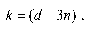
- By means of the invention, a design ratio k is introduced and defined as the ratio of the intermediate teeth span θinter over the coil span θ coil . The ratio k can be calculated directly by the numerator n and denominator d of the fractional number q, i.e. q=n/d. For a topology having additional teeth between adjacent phases, k is related to n and d by k=d/3-n, while k is found by k = d-3n for the topology having extra teeth per winding periodicity. These two governing equations can be used globally to obtain a desirable unity fundamental winding factor design for a specific slot-pole combination that has q that is less than 1/3 (for a three-phase machine).
Claims (13)
- A method (20) for providing an improved winding factor (kw1) of a 1-phase permanent magnet machine (1) having concentrated windings, said permanent magnet machine (1) comprising a stator (4) having a plurality of stator teeth (51, 52,..., 5n) separated by a plurality of stator slots (71, 72,..., 7n), said permanent magnet machine (1) further comprising a rotor (2) provided with a plurality of permanent magnets (31, 32,..., 3m) constituting magnetic poles, characterized by the steps of:- choosing (21) a slot/pole combination for said permanent magnet machine (1), providing a number of slots (Qs) per pole (p) per phase (1),- calculating (22) a ratio (k) of an intermediate tooth span θinter over a coil span θ coil based on said number of slots (Qs) per pole (p) per phase (1), where said coil span θ coil comprises a coil span between coils of each respective phase, and said intermediate tooth span θinter comprises a span between coils of two adjacent phases or between two consecutive winding sequences differing from said coil span θ coil , whereby an improved winding factor (kw1) is provided.
- The method (20) as claimed in claim 1, wherein said permanent magnet machine (1) comprises a three-phase machine.
- The method (20) as claimed in claim 2, wherein said step of choosing (21) a slot/pole combination further comprises defining a fractional number n/d = q, where


- The method (20) as claimed in claim 3, wherein said intermediate tooth span θinter comprises a span between two adjacent phases and wherein said step of calculating (22) said ratio (k) comprises utilizing the equation:

- The method (20) as claimed in claim 3, wherein said intermediate tooth span θinter comprises a span between two consecutive winding sequences and said step of calculating (22) said ratio (k) comprises utilizing the equation:

- The method (20) as claimed in any of the preceding claims, wherein said number (q) of stator slots (Qs) per pole (p) per phase (1) is less than 1/1.
- A permanent magnet machine (1) with concentrated windings comprising a stator (4) having a plurality of stator teeth (51, 52,..., 5n) separated by a plurality of stator slots (71, 72,..., 7n), said stator teeth (51, 52,..., 5n) being provided with electrical conductor windings/coil, said permanent magnet machine (1) further comprising a rotor (2) provided with a plurality of permanent magnets (31, 32,..., 3m), characterized in that said stator teeth (51, 52,..., 5n) and said stator slots (71, 72,..., 7n) are arranged in a pattern providing said stator (4) with differing spans θinter , θ coil , based on a ratio (k) of an intermediate tooth span θinter over a coil span θ coil in turn based on a number (q) of stator slots (Qs) per pole (p) per phase (1), where said coil span θ coil comprises a coil span between coils of each respective phase, and said intermediate tooth span θ inter comprises a span between two adjacent phases or between two consecutive winding sequences differing from said coil span θ coil , whereby an optimized winding factor (kw1) is provided.
- The permanent magnet machine (1) as claimed in claim 7, comprising additional stator teeth (11i) between two adjacent phases.
- The permanent magnet machine (1) as claimed in claim 7, comprising additional stator teeth (12i) between two consecutive winding sequences.
- The permanent magnet machine (1) as claimed in claim 8 or 9, wherein said additional stator teeth (11i, 12i) are free of windings.
- The permanent magnet machine (1) as claimed in any of claims 7-10, wherein said permanent magnet machine (1) comprises a motor or a generator.
- The permanent magnet machine (1) as claimed in any of claims 7-11, wherein intermediate space equal to said intermediate teeth span θinter is provided between two consecutive winding sequences or between two adjacent phases.
- The permanent magnet machine (1) as claimed in any of claims 7-12, wherein intermediate space equal to said intermediate teeth span θinter is provided between each of two consecutive winding sequences or between each of two adjacent phases.
Priority Applications (7)
| Application Number | Priority Date | Filing Date | Title |
|---|---|---|---|
| EP09153981A EP2224578A1 (en) | 2009-02-27 | 2009-02-27 | Stator winding scheme of a permanent magnet machine |
| PCT/EP2010/051491 WO2010097285A2 (en) | 2009-02-27 | 2010-02-08 | Stator with intermediate teeth |
| JP2011551453A JP2012519459A (en) | 2009-02-27 | 2010-02-08 | Stator permanent magnet machine winding configuration |
| CN201080007791.0A CN102318167B (en) | 2009-02-27 | 2010-02-08 | Stator with intermediate teeth |
| EP10702510A EP2401802A2 (en) | 2009-02-27 | 2010-02-08 | Stator with intermediate teeth |
| KR1020117019935A KR20110132346A (en) | 2009-02-27 | 2010-02-08 | Stator winding scheme of a permanent magnet machine |
| US13/219,660 US8680740B2 (en) | 2009-02-27 | 2011-08-27 | Stator with intermediate teeth |
Applications Claiming Priority (1)
| Application Number | Priority Date | Filing Date | Title |
|---|---|---|---|
| EP09153981A EP2224578A1 (en) | 2009-02-27 | 2009-02-27 | Stator winding scheme of a permanent magnet machine |
Publications (1)
| Publication Number | Publication Date |
|---|---|
| EP2224578A1 true EP2224578A1 (en) | 2010-09-01 |
Family
ID=40798130
Family Applications (2)
| Application Number | Title | Priority Date | Filing Date |
|---|---|---|---|
| EP09153981A Withdrawn EP2224578A1 (en) | 2009-02-27 | 2009-02-27 | Stator winding scheme of a permanent magnet machine |
| EP10702510A Withdrawn EP2401802A2 (en) | 2009-02-27 | 2010-02-08 | Stator with intermediate teeth |
Family Applications After (1)
| Application Number | Title | Priority Date | Filing Date |
|---|---|---|---|
| EP10702510A Withdrawn EP2401802A2 (en) | 2009-02-27 | 2010-02-08 | Stator with intermediate teeth |
Country Status (6)
| Country | Link |
|---|---|
| US (1) | US8680740B2 (en) |
| EP (2) | EP2224578A1 (en) |
| JP (1) | JP2012519459A (en) |
| KR (1) | KR20110132346A (en) |
| CN (1) | CN102318167B (en) |
| WO (1) | WO2010097285A2 (en) |
Cited By (6)
| Publication number | Priority date | Publication date | Assignee | Title |
|---|---|---|---|---|
| US9742228B2 (en) | 2013-10-18 | 2017-08-22 | General Electric Company | Torque ripple reduction in electric machines |
| EP3457531A3 (en) * | 2017-09-18 | 2019-08-07 | IFP Energies nouvelles | Electric machine comprising a stator provided with an inner tubular sleeve for the passage of a cooling fluid |
| CN111279587A (en) * | 2017-12-05 | 2020-06-12 | 依必安派特穆尔芬根有限两合公司 | Multi-tooth coil winding for 2-strand rotating field motor |
| WO2020208425A1 (en) * | 2019-04-09 | 2020-10-15 | Centre National De La Recherche Scientifique | A stator winding arrangement |
| EP3820024A4 (en) * | 2018-07-06 | 2021-08-18 | Mitsubishi Electric Corporation | Dynamo-electric machine |
| US11646579B2 (en) * | 2019-09-10 | 2023-05-09 | Rolls-Royce Plc | Electrical systems |
Families Citing this family (11)
| Publication number | Priority date | Publication date | Assignee | Title |
|---|---|---|---|---|
| US9359994B2 (en) | 2010-09-23 | 2016-06-07 | Northern Power Systems, Inc. | Module-handling tool for installing/removing modules into/from an electromagnetic rotary machine having a modularized active portion |
| US9281731B2 (en) | 2010-09-23 | 2016-03-08 | Northem Power Systems, Inc. | Method for maintaining a machine having a rotor and a stator |
| US8912704B2 (en) * | 2010-09-23 | 2014-12-16 | Northern Power Systems, Inc. | Sectionalized electromechanical machines having low torque ripple and low cogging torque characteristics |
| US11146123B2 (en) * | 2012-02-03 | 2021-10-12 | Green Ray Technologies, Llc | Electric machines with energizable and non-energizerable U-shaped stator segments |
| JP6327803B2 (en) * | 2013-07-09 | 2018-05-23 | 久慶 ▲ふく▼楊 | High-power, high-efficiency single-phase multipolar generator |
| DE102014200947A1 (en) * | 2014-01-20 | 2015-08-06 | Wobben Properties Gmbh | Synchronous generator of a gearless wind turbine |
| DE102016108712A1 (en) | 2016-05-11 | 2017-11-16 | Wobben Properties Gmbh | Synchronous generator of a gearless wind turbine and method for producing a synchronous generator and use of form coils |
| US10833543B2 (en) | 2017-10-02 | 2020-11-10 | Ge Aviation Systems Llc | Stator assembly |
| CN108880014B (en) * | 2018-05-29 | 2021-10-29 | 南方电机科技有限公司 | Stator, motor and automation equipment |
| CN109831085A (en) * | 2019-02-15 | 2019-05-31 | 深圳市配天电机技术有限公司 | Switched reluctance machines, electric car and electrical equipment |
| CN110739823B (en) * | 2019-12-11 | 2021-05-11 | 山东理工大学 | Permanent magnet driving motor of electric automobile |
Citations (1)
| Publication number | Priority date | Publication date | Assignee | Title |
|---|---|---|---|---|
| WO2006058871A2 (en) * | 2004-12-01 | 2006-06-08 | Siemens Aktiengesellschaft | Multi-polar permanently excited synchronous machine comprising tooth coils |
Family Cites Families (16)
| Publication number | Priority date | Publication date | Assignee | Title |
|---|---|---|---|---|
| US4883999A (en) * | 1988-08-15 | 1989-11-28 | Pacific Scientific Company | Polyphase electronically commutated reluctance motor |
| US5095238A (en) * | 1990-04-03 | 1992-03-10 | Minebea Co., Ltd. | Brushless dc motor and rotor magnet |
| US6094011A (en) * | 1995-06-26 | 2000-07-25 | Kokusan Denki Co., Ltd | Discharge lamp lighting device driven by internal combustion engine |
| JPH09233790A (en) * | 1996-02-27 | 1997-09-05 | Kokusan Denki Co Ltd | Internal combustion engine-driven generator for operating discharge lamp and discharge lamp operating device |
| JP3395071B2 (en) * | 1996-04-25 | 2003-04-07 | ミネベア株式会社 | Motor structure |
| JPH10234144A (en) * | 1997-02-19 | 1998-09-02 | Hitachi Ltd | Concentrated winding electric rotating machine |
| JPH11234990A (en) * | 1998-02-12 | 1999-08-27 | Okuma Corp | Permanent magnet motor |
| JP2000228838A (en) * | 1998-12-01 | 2000-08-15 | Toyota Motor Corp | Permanent magnet motor |
| JP4399943B2 (en) * | 2000-02-29 | 2010-01-20 | 株式会社富士通ゼネラル | Permanent magnet motor |
| US6909216B2 (en) | 2002-05-29 | 2005-06-21 | Matsushita Electric Industrial Co., Ltd. | Motor generator |
| JP2004215483A (en) * | 2002-05-29 | 2004-07-29 | Matsushita Electric Ind Co Ltd | Motor generator |
| JP2004304928A (en) * | 2003-03-31 | 2004-10-28 | Mitsuba Corp | Brushless motor |
| US7122933B2 (en) * | 2004-05-19 | 2006-10-17 | Emerson Electric Co. | Reduced coil segmented stator |
| DE102004055317A1 (en) * | 2004-11-16 | 2006-05-24 | Bosch Rexroth Aktiengesellschaft | Electric induction machine and primary section |
| US8084913B2 (en) * | 2005-10-06 | 2011-12-27 | Borgwarner Inc. | DC motor with asymmetrical poles |
| TW200847584A (en) * | 2007-05-25 | 2008-12-01 | Azure Shine Int Inc | Brushless permanent magnet motor with unequal width tooth slots and its manufacturing method |
-
2009
- 2009-02-27 EP EP09153981A patent/EP2224578A1/en not_active Withdrawn
-
2010
- 2010-02-08 CN CN201080007791.0A patent/CN102318167B/en active Active
- 2010-02-08 EP EP10702510A patent/EP2401802A2/en not_active Withdrawn
- 2010-02-08 JP JP2011551453A patent/JP2012519459A/en active Pending
- 2010-02-08 KR KR1020117019935A patent/KR20110132346A/en not_active Application Discontinuation
- 2010-02-08 WO PCT/EP2010/051491 patent/WO2010097285A2/en active Application Filing
-
2011
- 2011-08-27 US US13/219,660 patent/US8680740B2/en active Active
Patent Citations (1)
| Publication number | Priority date | Publication date | Assignee | Title |
|---|---|---|---|---|
| WO2006058871A2 (en) * | 2004-12-01 | 2006-06-08 | Siemens Aktiengesellschaft | Multi-polar permanently excited synchronous machine comprising tooth coils |
Non-Patent Citations (2)
| Title |
|---|
| FRIEDRICH J]RGEN K-H: "Bauformen und Betriebsverhalten modularer Dauermagnetmaschinen", DISSERTATION VON DER FAKULTAET FUER ELEKTROTECHNIK DERUNIVERSITAET DER BUNDESWEHR MUENCHEN, XX, XX, 1 January 1991 (1991-01-01), pages 1 - 41, XP002387835 * |
| KRASSER B: "Optimierte Auslegung einer Modularen Dauermagnetmaschine für ein autarkes Hybridfahrzeug, Kapitel 2", DISSERTATION FAKULTAET FUER ELEKTROTECHNIK UNDINFORMATIONSTECHNIK DER TECHNISCHEN UNIVERSITAET MUENCHEN ZURERLANGUNG DES AKADEMISCHEN GRADES EINES DOKTOR-INGENIEURS, XX, XX, 20 September 2000 (2000-09-20), pages 1 - 16, XP002355117 * |
Cited By (7)
| Publication number | Priority date | Publication date | Assignee | Title |
|---|---|---|---|---|
| US9742228B2 (en) | 2013-10-18 | 2017-08-22 | General Electric Company | Torque ripple reduction in electric machines |
| EP3457531A3 (en) * | 2017-09-18 | 2019-08-07 | IFP Energies nouvelles | Electric machine comprising a stator provided with an inner tubular sleeve for the passage of a cooling fluid |
| CN111279587A (en) * | 2017-12-05 | 2020-06-12 | 依必安派特穆尔芬根有限两合公司 | Multi-tooth coil winding for 2-strand rotating field motor |
| CN111279587B (en) * | 2017-12-05 | 2022-11-25 | 依必安派特穆尔芬根有限两合公司 | Multi-tooth coil winding for 2-strand rotating field motor |
| EP3820024A4 (en) * | 2018-07-06 | 2021-08-18 | Mitsubishi Electric Corporation | Dynamo-electric machine |
| WO2020208425A1 (en) * | 2019-04-09 | 2020-10-15 | Centre National De La Recherche Scientifique | A stator winding arrangement |
| US11646579B2 (en) * | 2019-09-10 | 2023-05-09 | Rolls-Royce Plc | Electrical systems |
Also Published As
| Publication number | Publication date |
|---|---|
| CN102318167B (en) | 2014-09-17 |
| WO2010097285A3 (en) | 2010-12-23 |
| KR20110132346A (en) | 2011-12-07 |
| US8680740B2 (en) | 2014-03-25 |
| CN102318167A (en) | 2012-01-11 |
| WO2010097285A2 (en) | 2010-09-02 |
| JP2012519459A (en) | 2012-08-23 |
| US20110309712A1 (en) | 2011-12-22 |
| EP2401802A2 (en) | 2012-01-04 |
Similar Documents
| Publication | Publication Date | Title |
|---|---|---|
| EP2224578A1 (en) | Stator winding scheme of a permanent magnet machine | |
| US9130431B2 (en) | Stator for rotary electrical machine | |
| US7474030B2 (en) | Magnetic coils for electrical machines | |
| US8471428B2 (en) | Rotating electrical machine | |
| US11063488B2 (en) | Stator for electric rotating machine | |
| US20100277027A1 (en) | Skew pattern for a permanent magnet rotor | |
| EP2362526A1 (en) | Stator for an energy converting apparatus and method for manufacturing the same | |
| EP2695284B1 (en) | Compact multiphase wave winding of a high specific torque electric machine | |
| US20080129137A1 (en) | Motor Winding | |
| US20060192457A1 (en) | Electric rotating machine | |
| US20220094228A1 (en) | Axial flux electrical machine | |
| WO2020178953A1 (en) | Power generator/electric motor and method for manufacturing same | |
| CN207994763U (en) | Two-phase rotary magnetic field motor | |
| CN110337772B (en) | Segmented stator motor | |
| US20110285142A1 (en) | Generator with Single Turn Wave Winding, Wind Turbine and Method for Determining the Thickness of the Slot Insulation of a Generator | |
| US20220094230A1 (en) | Axial flux electrical machine | |
| CN108288885B (en) | Voltage balancing winding pattern for an electric machine and method of assembling such a winding | |
| Spargo et al. | Synchronous reluctance motors with toroidal windings | |
| JP2518206B2 (en) | Winding method of brushless DC linear motor | |
| JP2024011223A (en) | Rotary electric machine | |
| EP2388893A1 (en) | Generator with single turn wave winding and wind turbine | |
| JP2009077490A (en) | One phase and multi-phase helical winding, flat and cylindrical multi-phase helical winding, multilayer helical winding, and gap-winding motor using helical windings | |
| JP2005204420A (en) | Stator for dynamo-electric machine | |
| JP2021141774A (en) | Stator of rotary electric machine, rotary electric machine, and vehicle drive unit | |
| JP2024003667A (en) | stator and motor |
Legal Events
| Date | Code | Title | Description |
|---|---|---|---|
| PUAI | Public reference made under article 153(3) epc to a published international application that has entered the european phase |
Free format text: ORIGINAL CODE: 0009012 |
|
| 17P | Request for examination filed |
Effective date: 20090227 |
|
| AK | Designated contracting states |
Kind code of ref document: A1 Designated state(s): AT BE BG CH CY CZ DE DK EE ES FI FR GB GR HR HU IE IS IT LI LT LU LV MC MK MT NL NO PL PT RO SE SI SK TR |
|
| AX | Request for extension of the european patent |
Extension state: AL BA RS |
|
| STAA | Information on the status of an ep patent application or granted ep patent |
Free format text: STATUS: THE APPLICATION HAS BEEN WITHDRAWN |
|
| 18W | Application withdrawn |
Effective date: 20100901 |