WO2021181730A1 - 希薄薬液供給装置 - Google Patents
希薄薬液供給装置 Download PDFInfo
- Publication number
- WO2021181730A1 WO2021181730A1 PCT/JP2020/034957 JP2020034957W WO2021181730A1 WO 2021181730 A1 WO2021181730 A1 WO 2021181730A1 JP 2020034957 W JP2020034957 W JP 2020034957W WO 2021181730 A1 WO2021181730 A1 WO 2021181730A1
- Authority
- WO
- WIPO (PCT)
- Prior art keywords
- chemical solution
- dilute
- dilute chemical
- storage tank
- supply device
- Prior art date
- Legal status (The legal status is an assumption and is not a legal conclusion. Google has not performed a legal analysis and makes no representation as to the accuracy of the status listed.)
- Ceased
Links
Images



Classifications
-
- B—PERFORMING OPERATIONS; TRANSPORTING
- B01—PHYSICAL OR CHEMICAL PROCESSES OR APPARATUS IN GENERAL
- B01F—MIXING, e.g. DISSOLVING, EMULSIFYING OR DISPERSING
- B01F23/00—Mixing according to the phases to be mixed, e.g. dispersing or emulsifying
- B01F23/40—Mixing liquids with liquids; Emulsifying
- B01F23/48—Mixing liquids with liquids; Emulsifying characterised by the nature of the liquids
- B01F23/483—Mixing liquids with liquids; Emulsifying characterised by the nature of the liquids using water for diluting a liquid ingredient, obtaining a predetermined concentration or making an aqueous solution of a concentrate
-
- H—ELECTRICITY
- H10—SEMICONDUCTOR DEVICES; ELECTRIC SOLID-STATE DEVICES NOT OTHERWISE PROVIDED FOR
- H10P—GENERIC PROCESSES OR APPARATUS FOR THE MANUFACTURE OR TREATMENT OF DEVICES COVERED BY CLASS H10
- H10P72/00—Handling or holding of wafers, substrates or devices during manufacture or treatment thereof
- H10P72/04—Apparatus for manufacture or treatment
- H10P72/0402—Apparatus for fluid treatment
-
- B—PERFORMING OPERATIONS; TRANSPORTING
- B01—PHYSICAL OR CHEMICAL PROCESSES OR APPARATUS IN GENERAL
- B01F—MIXING, e.g. DISSOLVING, EMULSIFYING OR DISPERSING
- B01F35/00—Accessories for mixers; Auxiliary operations or auxiliary devices; Parts or details of general application
- B01F35/20—Measuring; Control or regulation
- B01F35/21—Measuring
- B01F35/211—Measuring of the operational parameters
- B01F35/2112—Level of material in a container or the position or shape of the upper surface of the material
-
- B—PERFORMING OPERATIONS; TRANSPORTING
- B01—PHYSICAL OR CHEMICAL PROCESSES OR APPARATUS IN GENERAL
- B01F—MIXING, e.g. DISSOLVING, EMULSIFYING OR DISPERSING
- B01F35/00—Accessories for mixers; Auxiliary operations or auxiliary devices; Parts or details of general application
- B01F35/20—Measuring; Control or regulation
- B01F35/21—Measuring
- B01F35/2132—Concentration, pH, pOH, p(ION) or oxygen-demand
-
- B—PERFORMING OPERATIONS; TRANSPORTING
- B01—PHYSICAL OR CHEMICAL PROCESSES OR APPARATUS IN GENERAL
- B01F—MIXING, e.g. DISSOLVING, EMULSIFYING OR DISPERSING
- B01F35/00—Accessories for mixers; Auxiliary operations or auxiliary devices; Parts or details of general application
- B01F35/20—Measuring; Control or regulation
- B01F35/22—Control or regulation
- B01F35/221—Control or regulation of operational parameters, e.g. level of material in the mixer, temperature or pressure
- B01F35/2211—Amount of delivered fluid during a period
-
- B—PERFORMING OPERATIONS; TRANSPORTING
- B01—PHYSICAL OR CHEMICAL PROCESSES OR APPARATUS IN GENERAL
- B01F—MIXING, e.g. DISSOLVING, EMULSIFYING OR DISPERSING
- B01F35/00—Accessories for mixers; Auxiliary operations or auxiliary devices; Parts or details of general application
- B01F35/71—Feed mechanisms
- B01F35/717—Feed mechanisms characterised by the means for feeding the components to the mixer
- B01F35/7176—Feed mechanisms characterised by the means for feeding the components to the mixer using pumps
- B01F35/717613—Piston pumps
-
- C—CHEMISTRY; METALLURGY
- C02—TREATMENT OF WATER, WASTE WATER, SEWAGE, OR SLUDGE
- C02F—TREATMENT OF WATER, WASTE WATER, SEWAGE, OR SLUDGE
- C02F1/00—Treatment of water, waste water, or sewage
-
- C—CHEMISTRY; METALLURGY
- C02—TREATMENT OF WATER, WASTE WATER, SEWAGE, OR SLUDGE
- C02F—TREATMENT OF WATER, WASTE WATER, SEWAGE, OR SLUDGE
- C02F1/00—Treatment of water, waste water, or sewage
- C02F1/66—Treatment of water, waste water, or sewage by neutralisation; pH adjustment
-
- G—PHYSICS
- G05—CONTROLLING; REGULATING
- G05D—SYSTEMS FOR CONTROLLING OR REGULATING NON-ELECTRIC VARIABLES
- G05D11/00—Control of flow ratio
- G05D11/02—Controlling ratio of two or more flows of fluid or fluent material
- G05D11/13—Controlling ratio of two or more flows of fluid or fluent material characterised by the use of electric means
- G05D11/135—Controlling ratio of two or more flows of fluid or fluent material characterised by the use of electric means by sensing at least one property of the mixture
- G05D11/138—Controlling ratio of two or more flows of fluid or fluent material characterised by the use of electric means by sensing at least one property of the mixture by sensing the concentration of the mixture, e.g. measuring pH value
-
- H—ELECTRICITY
- H10—SEMICONDUCTOR DEVICES; ELECTRIC SOLID-STATE DEVICES NOT OTHERWISE PROVIDED FOR
- H10P—GENERIC PROCESSES OR APPARATUS FOR THE MANUFACTURE OR TREATMENT OF DEVICES COVERED BY CLASS H10
- H10P52/00—Grinding, lapping or polishing of wafers, substrates or parts of devices
-
- H—ELECTRICITY
- H10—SEMICONDUCTOR DEVICES; ELECTRIC SOLID-STATE DEVICES NOT OTHERWISE PROVIDED FOR
- H10P—GENERIC PROCESSES OR APPARATUS FOR THE MANUFACTURE OR TREATMENT OF DEVICES COVERED BY CLASS H10
- H10P72/00—Handling or holding of wafers, substrates or devices during manufacture or treatment thereof
- H10P72/04—Apparatus for manufacture or treatment
- H10P72/0402—Apparatus for fluid treatment
- H10P72/0406—Apparatus for fluid treatment for cleaning followed by drying, rinsing, stripping, blasting or the like
- H10P72/0411—Apparatus for fluid treatment for cleaning followed by drying, rinsing, stripping, blasting or the like for wet cleaning or washing
-
- H—ELECTRICITY
- H10—SEMICONDUCTOR DEVICES; ELECTRIC SOLID-STATE DEVICES NOT OTHERWISE PROVIDED FOR
- H10P—GENERIC PROCESSES OR APPARATUS FOR THE MANUFACTURE OR TREATMENT OF DEVICES COVERED BY CLASS H10
- H10P72/00—Handling or holding of wafers, substrates or devices during manufacture or treatment thereof
- H10P72/06—Apparatus for monitoring, sorting, marking, testing or measuring
- H10P72/0604—Process monitoring, e.g. flow or thickness monitoring
-
- B—PERFORMING OPERATIONS; TRANSPORTING
- B01—PHYSICAL OR CHEMICAL PROCESSES OR APPARATUS IN GENERAL
- B01F—MIXING, e.g. DISSOLVING, EMULSIFYING OR DISPERSING
- B01F2101/00—Mixing characterised by the nature of the mixed materials or by the application field
- B01F2101/24—Mixing of ingredients for cleaning compositions
Definitions
- a dilute chemical solution capable of stably and efficiently supplying a dilute chemical solution containing a solute such as an alkali, an oxidizing agent, or a gas at a very low concentration, which is effective in a cleaning / rinsing process of a semiconductor wafer or the like.
- a solute such as an alkali, an oxidizing agent, or a gas at a very low concentration
- dilute chemical solution in which a solute effective for controlling pH and oxidation-reduction potential is dissolved in ultrapure water at a very low concentration is used. May be used.
- This dilute chemical solution uses ultrapure water as a basic material, and in order to impart liquid properties such as pH and redox potential that match the purpose of each process such as cleaning process and rinsing process, acid / alkali and oxidant / reduction Agents may be added. In this case, it is desirable that the amount of these additions is the minimum necessary amount so as not to have an excessive influence on the silicon wafer.
- a method of adding a small amount of HCl or NH 4 OH (medicine injection) is generally used. Further, when the gas is dissolved in ultrapure water to maintain pH adjustment or inactivation, CO 2 gas or N 2 gas is dissolved. Furthermore, when you want to give reducing property. It has also been made to dissolve the H 2 gas.
- the flow rate fluctuates irregularly in the single-wafer type washer, but the chemical injection control that can sufficiently follow this irregular flow rate fluctuation has not been realized, and as a result, the liquid is poured into the wafer.
- the quality of the wash water and rinse water must be controlled in a wide range deviating from the ideal value range.
- Reusing surplus water (surplus dilute chemical solution), especially surplus water after passing through a heating device means that oxidizing agents such as H 2 O 2 and O 3 spontaneously decompose themselves and other substances. It is unsuitable from the viewpoint of strict concentration control because it tends to decompose and fluctuate in concentration due to the reaction with the chemical solution.
- the concentration of the dissolved gas before being returned to the storage tank via the gas-permeable tube or tank There is a problem that it decreases.
- the present invention has been made in view of the above problems, and provides a dilute chemical solution supply device suitable for cleaning wafers and the like, which can accurately adjust the concentration of the solute of the dilute chemical solution and suppresses the discharge of excess water.
- the purpose is to do.
- the present invention comprises a dilute chemical solution manufacturing unit for producing a dilute chemical solution having a predetermined concentration of the chemical solution by adding a predetermined amount of the chemical solution to the flow rate of ultrapure water.
- a storage tank for storing the manufactured dilute chemical solution, a dilute chemical solution supply mechanism for supplying the dilute chemical solution to the use point, a return pipe for returning the surplus dilute chemical solution at the use point to the storage tank, and the return pipe.
- a dilute chemical solution supply device including a return mechanism provided with a concentration detecting means for the chemical solution component provided on the way (Invention 1).
- invention 1 after adding a predetermined amount of a chemical solution to ultrapure water to produce a dilute chemical solution having a predetermined concentration, it is temporarily stored in a storage tank and supplied from this storage tank to a use point. can do. Then, the surplus dilute chemical solution is returned to the storage tank after detecting the concentration of the chemical solution component, and the surplus dilute chemical solution can be reused by appropriately controlling the concentration of the dilute chemical solution in the storage tank.
- the dilute chemical solution supply mechanism includes a gas dissolving means for dissolving a predetermined gas component in the dilute chemical solution supplied from the storage tank (Invention 2).
- the diluted chemical solution manufacturing unit includes a plunger pump to which the chemical solution is added (Invention 3).
- a plunger pump controls the amount of a small amount of chemical solution added with respect to the flow rate of ultrapure water to stably supply a diluted chemical solution having a predetermined concentration to the storage tank. Can be done.
- the dilute chemical solution manufacturing unit is provided with a chemical solution addition device including a closed tank for storing the chemical solution and an inert gas supply means for supplying the inert gas to the closed tank.
- a chemical solution addition device including a closed tank for storing the chemical solution and an inert gas supply means for supplying the inert gas to the closed tank.
- the dilute chemical solution having a predetermined concentration is stably supplied to the storage tank by extruding the chemical solution into an inert gas with respect to the flow rate of ultrapure water and supplying a predetermined amount of the chemical solution. can do.
- the storage tank is provided with a level sensor for detecting the water level of the storage tank, and based on the water level information of the storage tank by the level sensor, the dilute chemical solution manufacturing unit. It is preferable that the production / shutdown of the dilute chemical solution can be controlled (Invention 5).
- the dilute chemical solution manufacturing unit when the water level in the storage tank falls below a certain level, the dilute chemical solution manufacturing unit is operated to efficiently produce the dilute chemical solution and eliminate the generation of excess water. Can be done.
- the storage tank is provided with a discharge mechanism (Invention 6).
- the dilute drug solution has a predetermined concentration in the storage tank by discharging the dilute drug solution without storing it in the storage tank until the dilute drug solution stabilizes at the predetermined concentration. Can be stored, so the concentration of the dilute chemical solution supplied to the point of use can be controlled accurately.
- the water level in the storage tank can be efficiently controlled by adjusting the production amount of the dilute chemical solution according to the water level in the storage tank.
- the concentration of the dilute drug solution supplied to the use point is accurately controlled by differentiating the storage tank for supplying the dilute drug solution to the use point and the storage tank for storing the dilute drug solution. It becomes possible.
- the gas supplied from the gas dissolving means can be accurately and efficiently dissolved in the dilute chemical solution.
- the concentration of the chemical solution component of the surplus dilute chemical solution after being supplied to the use point can be detected and then returned to the storage tank, so that the concentration of the dilute chemical solution in the storage tank can be adjusted.
- excess dilute chemicals can be reused. As a result, it is possible to reduce the amount of ultrapure water used as raw water.
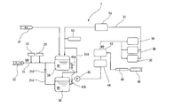
- FIG. 1 shows a dilute chemical solution supply device according to the first embodiment of the present invention.
- the dilute chemical solution supply device 1 uses a dilute chemical solution preparation unit 2 for preparing the dilute chemical solution W1, a storage tank 3 for the prepared dilute chemical solution, and a dilute chemical solution W1 stored in the storage tank 3 for washing water.
- the dilute chemical solution adjusting / supplying mechanism 4 for supplying to a plurality of single-wafer type washing machines 5A, 5B and 5C as a point of use, and the single-wafer type washing machines 5A, 5B and 5C connected to the single-wafer type washing machines 5A, 5B and 5C, respectively. It consists of a return mechanism that returns excess water from the washing machine to the storage tank 3.
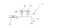
- the dilute chemical solution preparation unit 2 has a dilute chemical solution preparation flow path 21 that communicates the ultrapure water (DIW) W supply source 22 and the storage tank 3, and a first chemical solution provided in the middle of the dilute chemical solution preparation flow path 21. It has a supply mechanism 23 of the above and a supply mechanism 24 of a second chemical solution. Then, in the present embodiment, the first chemical solution supply mechanism 23 and the second chemical solution supply mechanism 24 are the first chemical solution tank 23A and the plunger pump 23B for adding the chemical solution, as shown in FIG. , A second chemical solution tank 24A and a plunger pump 24B for adding the chemical solution, respectively.
- the dilute chemical solution preparation flow path 21 is provided with a flow rate measuring means such as a flow meter (not shown).
- the storage tank 3 is made of a high-purity material whose elution from the inner wall is negligible so as not to impair the purity of the dilute chemical solution W1.
- the storage tank 3 is connected to an N 2 gas supply mechanism 31 for filling the inside of the storage tank 3 with N 2 gas as an inert gas, and a return mechanism 32 for discharging the dilute chemical solution in the storage tank 3, respectively.
- the storage tank 3 is provided with a level sensor 33 for detecting the water level as shown in FIG.
- the return mechanism 32 includes a return flow path 34 having an opening / closing mechanism (not shown) and a removal device 35 such as an ion exchange resin column provided in the return flow path 34, and the return flow.
- the road 34 communicates with the dilute chemical solution preparation unit 2 on the downstream side of the removal device 35.
- the dilute chemical solution adjusting / supplying mechanism 4 includes a dilute chemical solution supply flow path 41 that communicates the storage tank 3 with the single-wafer cleaning machines 5A, 5B, and 5C, and a liquid transfer system provided in the middle of the dilute chemical solution supply flow path 41. It has a booster pump 42 as a pump, a gas dissolving film 43, and a gas removing film 44 provided in front of the gas dissolving film 43. A dissolved gas source 45 and a mass flow controller (MFC) 46 as a flow rate control means are connected to the gas dissolution film 43.
- the dilute chemical solution adjusting / supplying mechanism 4 is provided by imparting a gas dissolving function to the dilute chemical solution supply mechanism.
- the washing machines 5A, 5B, and 5C are connected to a return flow path 51 that returns to the storage tank 2 as a return mechanism, and the return flow path 51 is connected to the gas removal membrane 52 and the first.
- An online monitor 53 for measuring and displaying the concentration of the chemical solution and / or the second chemical solution is provided.
- the online monitor 53 that detects the concentration of the second chemical solution communicates with a control device such as a personal computer (not shown), and is based on the flow rate of the dilute chemical solution preparation flow path 21, the level sensor 33, and the measured values of the online monitor 53. Therefore, it is possible to control the opening and closing of the return flow path 34, the adjustment of the supply amount of the first chemical solution supply mechanism 23 and the second chemical solution supply mechanism 24, and the like.
- the ultrapure water W is supplied from the supply source 22 of the ultrapure water (DIW) W, and the first chemical solution supply mechanism 23 and the second chemical solution supply mechanism 24 are used. Supply the chemical solution of the above and the chemical solution of the second.
- the plunger pump 23B and the plunger pump 24B are controlled by the control device so that the first chemical solution and the second chemical solution have a predetermined concentration based on the flow rate of the dilute chemical solution preparation flow path 21, and the first chemical solution is used. Adjust the amount of the chemical solution and the second chemical solution added.
- the ultrapure water W serving as raw water is, for example, resistivity: 18.1 M ⁇ ⁇ cm or more, fine particles: 1000 cells / L or less with a particle size of 50 nm or more, viable bacteria: 1 cell / L or less, TOC. (Total Organic Carbon): 1 ⁇ g / L or less, total silicon: 0.1 ⁇ g / L or less, metals: 1 ng / L or less, ions: 10 ng / L or less, hydrogen peroxide; 30 ⁇ g / L or less, water temperature: 25 ⁇ The one at 2 ° C. is preferable.
- a pH adjuster is suitable.
- the pH adjusting agent is not particularly limited, but when adjusting the pH to less than 7, an acidic solution such as hydrochloric acid, nitric acid, sulfuric acid, or acetic acid can be used.
- an alkaline solution such as ammonia, sodium hydroxide, potassium hydroxide or TMAH can be used.
- an oxidation-reduction potential adjusting agent is suitable.
- the redox potential adjusting agent hydrogen peroxide solution or the like can be used when the redox potential is adjusted to be high. Further, when adjusting the redox potential to be low, a solution of oxalic acid, hydrogen sulfide, potassium iodide or the like can be used.
- Both of these first chemicals or the second chemicals may be added, or either one may be added, and when either one is added, the supply mechanism 24 of the second chemicals may not be provided. .. In this way, by controlling the addition amount of either or both of the first chemical solution and the second chemical solution so as to have a predetermined concentration by the control device based on the flow rate of the ultrapure water W, it is desired. Prepare a dilute chemical solution W1.
- the dilute chemical solution W1 thus prepared is supplied to the storage tank 3 as it is.
- fluctuations in pH and redox potential due to an increase in the dissolved gas in the dilute chemical solution W1 in the storage tank 3 can be suppressed.
- the storage tank 3 is provided with the level sensor 33 as shown in FIG. 3, if the amount of water retained in the storage tank 3 falls below a certain level based on the output of the level sensor 33, By controlling the dilute chemical solution preparation unit 2 so as to start the production of the dilute chemical solution W1, it is possible to efficiently produce the dilute chemical solution W1. At this time, even when the water level of the storage tank 3 is above a certain level and the manufacturing unit is stopped, the dilute chemical solution preparation unit 2 keeps passing ultrapure water W at a very small flow rate to make it dilute. The inside of the system of the chemical solution preparation unit 2 can be kept clean. The ultrapure water that has passed through at this time may be drained or recirculated and merged with the supply source 22 side of the ultrapure water W.
- the solute concentration of the dilute chemical solution W1 may not be stable and may not fall within the predetermined concentration range. Therefore, the time required for the concentration of the prepared dilute chemical solution W1 to stabilize and the amount of treatment are investigated in advance, and until that point, the dilute chemical solution W1 is discharged from the return mechanism 32 without being stored in the storage tank 3. Therefore, the solute concentration of the dilute chemical solution W1 stored in the storage tank 3 can be accurately controlled.
- the amount discharged at this time is wastewater, but the amount of water in the whole is small.
- the dilute chemical solution W1 is discharged by removing the first chemical solution and / or the second chemical solution component by a removing device 35 such as an ion exchange resin column provided in the return flow path 34 as shown in FIG. Therefore, the amount of wastewater may be reduced by returning the product to the dilute chemical preparation unit 2 side.
- a sensor for measuring the concentration of the first chemical solution and / or the second chemical solution may be provided in the storage tank 3 so that the solute concentration of the dilute chemical solution W1 is discharged until it reaches a predetermined range. ..
- the dilute chemical solution W1 stored in the storage tank 3 is fed by a booster pump 42 as a liquid feeding means provided in the subsequent stage of the storage tank 3.
- the gas supplied from the dissolved gas source 45 is dissolved in the gas removing membrane 44 to obtain the washing water W2. adjust.
- MFC mass flow controller
- dissolved gas for example, hydrogen, ozone, CO 2 and the like may be selected in various ways depending on the cleaning purpose.
- the cleaning water W2 prepared with the diluted chemical solution W1 in this manner is supplied to the cleaning machines 5A, 5B and 5C.
- the excess washing water W2 not used in the washing machines 5A, 5B and 5C is returned to the storage tank 3 from the return flow path 51. There is no problem if the excess washing water W2 is returned to the storage tank 3 as it is, but the concentration of the first chemical solution and / or the second chemical solution drops below a predetermined value due to the self-decomposition of the oxidizing agent or the reaction with the chemical solution.
- the plurality of single-wafer cleaning machines 5A, 5B and 5C are multi-chamber single-wafer cleaning machines in which a large number of valves open and close irregularly. In the cleaning and rinsing process, it is possible to realize a supply that keeps the extremely important liquid quality at the desired value accurately and stably, and significantly reduces the dripping of excess cleaning water W2 (dilute chemical solution W1), resulting in ultrapure water W. Waste can be prevented.
- the dilute chemical solution supply device according to the second embodiment of the present invention will be described with reference to FIG. Since the dilute chemical solution supply device of the present embodiment basically has the same configuration as that of the first embodiment described above, the same configuration is designated by the same reference numerals and detailed description thereof will be omitted.
- the dilute chemical solution supply device is provided with two storage tanks 3A and 3B in parallel, and the branch pipe 21A of the dilute chemical solution preparation flow path 21 having an on-off valve 21B is connected to the storage tank 3B and returned.
- the branch pipe 51A of the road 51 is connected to the storage tank 3B, and switching valves 41A and 41B are provided in the dilute chemical solution supply flow path 41, respectively.
- Two or more storage tanks are installed in parallel as in the present embodiment, and the storage tank for storing the dilute chemical solution W1 from the dilute chemical solution preparation flow path 21 is set as one (for example, the storage tank 3A), and the dilute chemical solution W1 is stored. Then, the on-off valve 21B is opened so as to supply the dilute chemical solution W1 to the storage tank 3B. Then, while the switching valve 41A is opened, the switching valve 41B is closed and the washing water W2 is sequentially sent from the storage tank 3A to the single-wafer type washing machines 5A, 5B and 5C, and during that time, the washing water W2 is sent to the storage tank 3B waiting to be fed. The dilute chemical solution W1 is stored. Next, on the contrary, each valve may be switched to supply the dilute chemical solution W1 from the storage tank 3B and store the dilute chemical solution W1 in the storage tank 3A.
- the concentration of the dilute chemical solution W1 can be stabilized. It is possible to achieve both stable supply.
- the dilute chemical solution supply device of the present invention has been described above based on the above embodiment, the present invention is not limited to the above embodiment and various modifications can be carried out.
- the first chemical solution supply mechanism 23 and the second chemical solution supply mechanism 24 are not limited to those shown in FIG. 2, and as shown in FIG. 5, the first chemical solution tank 23A and the second chemical solution tank 23A and the second chemical solution tank 24A and a closed tank, via a supply pipe 26 from the N 2 gas supply source 25 to the first chemical solution tank 23A and the second chemical liquid tank 24A, by supplying N 2 gas as the inert gas,
- the first chemical solution and the second chemical solution may be pumped to dissolve the first chemical solution and the second chemical solution so as to have a desired solute concentration.
- the desired gas component is dissolved in the dilute chemical solution W1 by the gas dissolution membrane 43 to obtain the washing water W2, but the gas dissolution membrane 43 and the gas removal membrane are used.
- the 44 is not always necessary, and the dilute chemical solution W1 may be supplied as it is as the washing water W2 as a dilute chemical solution supply mechanism, or only the gas removal membrane 44 may be provided.
- the point of use is not limited to the leaf-to-leaf washer, but can be applied to devices that use various dilute chemicals.
- the present invention is suitable for a device whose use point consists of a device using a plurality of dilute chemical solutions, but a device using one dilute chemical solution may also be used.
- Dilute chemical solution supply device 2 Dilute chemical solution preparation unit 21 Dilute chemical solution preparation flow path 21A Branch tube 21B On-off valve 22 Ultra-pure water supply source 23 First chemical solution supply mechanism 23A First chemical solution tank 23B Plunger pump 24 Second Chemical solution supply mechanism 24A Second chemical solution tank 24B Plunger pump 25 N 2 Gas (inert gas) supply source 26 Supply pipes 3, 3A, 3B Storage tank 31 N 2 Gas supply mechanism (inert gas supply mechanism) 32 Return mechanism 33 Level sensor 34 Return flow path 35 Removal device 4 Dilute chemical solution adjustment / supply mechanism 41 Dilute chemical solution supply flow path 41A, 41B Switching valve 42 Booster pump (liquid transfer pump) 43 Gas dissolution membrane 44 Gas removal membrane 45 Dissolved gas source 46 Mass flow controller (flow control means) 5A, 5B, 5C leaf type washer (use point) 51 Return flow path 52 Gas removal membrane 53 Online monitor (concentration sensor) W Ultrapure water W1 Dilute chemical solution W2 Washing water
Landscapes
- Chemical & Material Sciences (AREA)
- Chemical Kinetics & Catalysis (AREA)
- Engineering & Computer Science (AREA)
- Life Sciences & Earth Sciences (AREA)
- Hydrology & Water Resources (AREA)
- Environmental & Geological Engineering (AREA)
- Water Supply & Treatment (AREA)
- Organic Chemistry (AREA)
- Physics & Mathematics (AREA)
- General Physics & Mathematics (AREA)
- Automation & Control Theory (AREA)
- Cleaning Or Drying Semiconductors (AREA)
Abstract
希薄薬液供給装置1は、希薄薬液W1を調製する希薄薬液調製部2と、この調製された希薄薬液の貯留槽3と、この貯留槽3に貯留された希薄薬液W1を洗浄水W2として複数台の枚葉式洗浄機5A、5B及び5Cに供給する希薄薬液調整・供給機構4と、枚葉式洗浄機5A、5B及び5Cにそれぞれ接続した、該枚葉式洗浄機の余剰水を貯留槽3に還流する返送機構とからなる。このような希薄薬液供給装置であれば、希薄薬液の溶質の濃度を精度よく調整可能であり、かつ余剰水の排出を抑制することができ、ウェハなどの洗浄に好適である。
Description
本発明は、半導体用ウェハなどの洗浄・リンス工程において有効な、アルカリ、酸化剤、ガス等の溶質をごく低濃度に含む希薄薬液を安定的にかつ効率良く供給することの可能な希薄薬液供給装置に関する。
半導体の製造工程において、半導体用シリコンウェハなどの洗浄工程では、pHや酸化還元電位の制御に有効な溶質を超純水にごく低濃度溶解した水(以下、希薄薬液と呼ぶことがある)が使われることがある。この希薄薬液は、超純水を基本材料として、洗浄工程やリンス工程などそれぞれの工程の目的に合致したpHや酸化還元電位などの液性を付与するために、酸・アルカリ、酸化剤・還元剤を添加することがある。この場合、これらの添加量はシリコンウェハに過度な影響を及ぼさないためには必要最少量であることが望ましい。ここで、pH調整には、一般にHClやNH4OHを微量添加(薬注)する方法が活用されている。また、超純水にガスを溶解させてpH調整あるいは不活性化を保持させる場合には、CO2ガスやN2ガスを溶解することが行われている。さらに、還元性を付与したい場合には。H2ガスを溶解することも行われている。
このような薬液の添加方法としては、プランジャポンプなどのポンプを用いる方法、密閉容器に充填した薬液をN2ガスなどの不活性ガスにより加圧して押し出す方法などが実用化されている。
この場合において、薬注は超純水の流量が一定であれば、所望の溶質濃度にすることは容易であるが、実際に希薄薬液が用いられる洗浄機、特に複数の洗浄チャンバを有する枚葉式の洗浄機では、ウェハに注がれる水の供給・停止が複数のバルブの開閉で制御されているため、希薄薬液の流量が不規則に変動する。この変動に対して、希薄薬液の溶質濃度が所望とする範囲に収まるように、超純水の流量に対する薬液の添加量を比例制御や濃度モニターの信号を受けてのPID制御など様々な手法によってコントロールすることが行われている。
上述したように、枚葉式の洗浄機では流量が不規則に変動するが、この不規則な流量変動に十分に追従可能な薬注コントロールは実現できておらず、結果としてウェハに注がれる洗浄水・リンス水の液質は、理想とする値の範囲から逸脱した広い範囲での制御とせざるを得ない、という問題点があった。
そこで、希薄薬液の濃度の安定化を優先し、過剰量の希薄薬液を一定の条件で製造し供給し続けることが考えられるが、この場合、余剰の希薄薬液を多量に排出することになる。近年の複数の洗浄チャンバを有する枚葉式洗浄機では、瞬間的に必要となる希薄薬液の最大流量と最低流量の差が大きくなるが、希薄薬液の最大流量より多くの希薄薬液を連続供給すると相当量の余剰水(余剰希薄薬液)を排出することになり、用排水設備への負担、希薄薬液の過剰な排出、ひいては基本材料としての超純水を過剰に浪費することになるなどの点で問題がある。
余剰水(余剰希薄薬液)、特に加熱装置を通過した後の余剰水をそのまま再利用することは、H2O2やO3など酸化性を有する酸化剤が、それ自体の自然分解および他の薬液との反応により分解して濃度が変動する傾向にあるため、厳密な濃度のコントロールの観点からは不適である。同様にH2ガス、CO2ガスなどを溶解させたガス溶解水の余剰水においても、ガス透過性を有するチューブやタンクを経て貯留槽に返送されるまでの間に、溶解したガスの濃度が低下してしまう、という問題点がある。
本発明は上記課題に鑑みてなされたものであり、希薄薬液の溶質の濃度を精度よく調整可能であり、かつ余剰水の排出を抑制した、ウェハなどの洗浄に好適な希薄薬液供給装置を提供することを目的とする。
上述した目的を達成するために、本発明は、超純水の流量に対して所定量の薬液を添加することで、該薬液の所定の濃度の希薄薬液を製造する希薄薬液製造部と、この製造された希薄薬液を貯留する貯留槽と、前記希薄薬液をユースポイントに供給する希薄薬液供給機構と、前記ユースポイントでの余剰の希薄薬液を貯留槽にまで返送する返送配管及び該返送配管の途中に設けられた前記薬液成分の濃度検知手段を備えた返送機構とを備える、希薄薬液供給装置を提供する(発明1)。
かかる発明(発明1)によれば、超純水に対して所定量の薬液を添加して、所定の濃度の希薄薬液を製造したら、一旦貯留槽に貯留し、この貯留槽からユースポイントに供給することができる。そして、余剰の希薄薬液は、薬液成分の濃度を検知した上で貯留槽に返送して、貯留槽の希薄薬液の濃度を適切に管理することで余剰の希薄薬液を再利用することができる。
上記発明(発明1)においては、前記希薄薬液供給機構が前記貯留槽から供給された希薄薬液に所定のガス成分を溶解するガス溶解手段を備えることが好ましい(発明2)。
かかる発明(発明2)によれば、希薄薬液にさらにガスを溶解した薬液とすることができる。
上記発明(発明1,2)においては、前記希薄薬液製造部が前記薬液を添加するプランジャポンプを備えることが好ましい(発明3)。
かかる発明(発明3)によれば、プランジャポンプにより、超純水の流量に対して微量の薬液の添加量を制御することにより、所定の濃度の希薄薬液を貯留槽に安定的に供給することができる。
上記発明(発明1,2)においては、希薄薬液製造部が、前記薬液を貯留する密閉タンクと該密閉タンクに不活性ガスを供給する不活性ガス供給手段とからなる薬液添加装置を備えることが好ましい(発明4)。
かかる発明(発明4)によれば、超純水の流量に対して不活性ガスに薬液を押し出して所定量の薬液を供給することで、所定の濃度の希薄薬液を貯留槽に安定的に供給することができる。
上記発明(発明1~4)においては、前記貯留槽に該貯留槽の水位を検知するレベルセンサが設けられており、このレベルセンサによる貯留槽の水位情報に基づいて、希薄薬液製造部での希薄薬液の製造・停止が制御可能となっていることが好ましい(発明5)。
かかる発明(発明5)によれば、貯留槽の水位が一定のレベルを下回ったら希薄薬液製造部を稼働することで、希薄薬液を効率良く製造することができ、余剰水の発生を排除することができる。
上記発明(発明1~5)においては、前記貯留槽に排出機構を備えることが好ましい(発明6)。
かかる発明(発明6)によれば、前記希薄薬液が前記所定の濃度で安定するまで、前記希薄薬液を前記貯留槽に貯留せずに排出することにより、貯留槽内に所定の濃度の希薄薬液を貯留することができるので、ユースポイントに供給する希薄薬液の濃度を精度よくコントロールすることが可能となる。
上記発明(発明5,6)においては、前記希薄薬液製造部における希薄薬液の製造量が調整可能であることが好ましい(発明7)。
かかる発明(発明7)によれば、貯留槽の水位に応じて希薄薬液の製造量を調整することで、貯留槽の水位を効率良く制御することができる。
上記発明(発明1~7)においては、前記貯留槽が2槽以上並列に設けられていることが好ましい(発明8)。
かかる発明(発明8)によれば、ユースポイントに希薄薬液を供給する貯留槽と、希薄薬液を貯留する貯留槽とを異ならせることにより、ユースポイントに供給する希薄薬液の濃度を精度よくコントロールすることが可能となる。
上記発明(発明2~8)においては、前記ガス溶解手段の前段に前記希薄薬液中の溶存ガスを除去するガス除去手段を備えることが好ましい(発明9)。
かかる発明(発明9)によれば、希薄薬液にガス溶解手段から供給するガスを精度よくかつ効率的に溶解することができる。
本発明の希薄薬液供給装置によれば、ユースポイントに供給した後の余剰の希薄薬液の薬液成分の濃度を検知した上で貯留槽に返送することができるので、貯留槽の希薄薬液の濃度を適切に管理することで余剰の希薄薬液を再利用することができる。これにより、使用する原水としての超純水を節減することもできる。
<第一の実施形態>
[希薄薬液供給装置]
図1は、本発明の第一の実施形態による希薄薬液供給装置を示している。図1において、希薄薬液供給装置1は、希薄薬液W1を調製する希薄薬液調製部2と、この調製された希薄薬液の貯留槽3と、この貯留槽3に貯留された希薄薬液W1を洗浄水W2として、ユースポイントとしての複数台の枚葉式洗浄機5A、5B及び5Cに供給する希薄薬液調整・供給機構4と、枚葉式洗浄機5A、5B及び5Cにそれぞれ接続した、該枚葉式洗浄機の余剰水を貯留槽3に還流する返送機構とからなる。
[希薄薬液供給装置]
図1は、本発明の第一の実施形態による希薄薬液供給装置を示している。図1において、希薄薬液供給装置1は、希薄薬液W1を調製する希薄薬液調製部2と、この調製された希薄薬液の貯留槽3と、この貯留槽3に貯留された希薄薬液W1を洗浄水W2として、ユースポイントとしての複数台の枚葉式洗浄機5A、5B及び5Cに供給する希薄薬液調整・供給機構4と、枚葉式洗浄機5A、5B及び5Cにそれぞれ接続した、該枚葉式洗浄機の余剰水を貯留槽3に還流する返送機構とからなる。
(希薄薬液調製部)
希薄薬液調製部2は、超純水(DIW)Wの供給源22及び貯留槽3を連通する希薄薬液調製流路21と、この希薄薬液調製流路21の途中に設けられた第一の薬液の供給機構23と、第二の薬液の供給機構24とを有する。そして、これら第一の薬液の供給機構23及び第二の薬液の供給機構24は、本実施形態においては、図2に示すように第一の薬液のタンク23A及び薬液を添加するプランジャポンプ23Bと、第二の薬液のタンク24A及び薬液を添加するプランジャポンプ24Bとからそれぞれ構成される。なお、希薄薬液調製流路21には、図示しない流量計などの流量計測手段が設けられている。
希薄薬液調製部2は、超純水(DIW)Wの供給源22及び貯留槽3を連通する希薄薬液調製流路21と、この希薄薬液調製流路21の途中に設けられた第一の薬液の供給機構23と、第二の薬液の供給機構24とを有する。そして、これら第一の薬液の供給機構23及び第二の薬液の供給機構24は、本実施形態においては、図2に示すように第一の薬液のタンク23A及び薬液を添加するプランジャポンプ23Bと、第二の薬液のタンク24A及び薬液を添加するプランジャポンプ24Bとからそれぞれ構成される。なお、希薄薬液調製流路21には、図示しない流量計などの流量計測手段が設けられている。
(貯留槽)
貯留槽3は、希薄薬液W1の純度を損なわないために内壁からの溶出が無視できるレベルである高純度の材質製とする。貯留槽3には、該貯留槽3内を不活性ガスとしてのN2ガスで満たすためのN2ガス供給機構31と、貯留槽3内の希薄薬液を排出する返送機構32とがそれぞれ接続されている。本実施形態においては、この貯留槽3には、図3に示すようにその水位を検知するレベルセンサ33が設けられている。また、本実施形態においては、返送機構32は図示しない開閉機構を備えた返送流路34と、この返送流路34に設けられたイオン交換樹脂カラムなどの除去装置35とを備え、該返送流路34はこの除去装置35の下流側で希薄薬液調製部2に連通している。
貯留槽3は、希薄薬液W1の純度を損なわないために内壁からの溶出が無視できるレベルである高純度の材質製とする。貯留槽3には、該貯留槽3内を不活性ガスとしてのN2ガスで満たすためのN2ガス供給機構31と、貯留槽3内の希薄薬液を排出する返送機構32とがそれぞれ接続されている。本実施形態においては、この貯留槽3には、図3に示すようにその水位を検知するレベルセンサ33が設けられている。また、本実施形態においては、返送機構32は図示しない開閉機構を備えた返送流路34と、この返送流路34に設けられたイオン交換樹脂カラムなどの除去装置35とを備え、該返送流路34はこの除去装置35の下流側で希薄薬液調製部2に連通している。
(希薄薬液調整・供給機構)
希薄薬液調整・供給機構4は、貯留槽3と枚葉式洗浄機5A、5B及び5Cとを連通する希薄薬液供給流路41と、この希薄薬液供給流路41の途中に設けられた送液ポンプとしてのブースターポンプ42と、ガス溶解膜43と、このガス溶解膜43の前段に設けられたガス除去膜44とを有する。このガス溶解膜43には、溶解ガス源45と流量制御手段としてのマスフロコントローラ(MFC)46とが接続している。なお、本実施形態においては、希薄薬液供給機構にガス溶解機能を付与することで希薄薬液調整・供給機構4としている。
希薄薬液調整・供給機構4は、貯留槽3と枚葉式洗浄機5A、5B及び5Cとを連通する希薄薬液供給流路41と、この希薄薬液供給流路41の途中に設けられた送液ポンプとしてのブースターポンプ42と、ガス溶解膜43と、このガス溶解膜43の前段に設けられたガス除去膜44とを有する。このガス溶解膜43には、溶解ガス源45と流量制御手段としてのマスフロコントローラ(MFC)46とが接続している。なお、本実施形態においては、希薄薬液供給機構にガス溶解機能を付与することで希薄薬液調整・供給機構4としている。
(返送機構)
本実施形態においては、洗浄機5A、5B及び5Cには、返送機構として貯留槽2に還流する返送流路51がそれぞれ接続されており、この返送流路51にはガス除去膜52と第一の薬液及び/又は第二の薬液の濃度を計測表示するオンラインモニタ53とが設けられている。
本実施形態においては、洗浄機5A、5B及び5Cには、返送機構として貯留槽2に還流する返送流路51がそれぞれ接続されており、この返送流路51にはガス除去膜52と第一の薬液及び/又は第二の薬液の濃度を計測表示するオンラインモニタ53とが設けられている。
(制御装置)
上述した構成において、第一の薬液の供給機構23、第二の薬液の供給機構24、希薄薬液調製流路21の流量計、レベルセンサ33、返送流路34の開閉機構、及び第一の薬液及び第二の薬液の濃度を検知するオンラインモニタ53は、図示しないパーソナルコンピュータなどの制御装置に連通しており、希薄薬液調製流路21の流量、レベルセンサ33、オンラインモニタ53の計測値に基づいて、返送流路34の開閉、第一の薬液の供給機構23及び第二の薬液の供給機構24の供給量の調整などを制御可能となっている。
上述した構成において、第一の薬液の供給機構23、第二の薬液の供給機構24、希薄薬液調製流路21の流量計、レベルセンサ33、返送流路34の開閉機構、及び第一の薬液及び第二の薬液の濃度を検知するオンラインモニタ53は、図示しないパーソナルコンピュータなどの制御装置に連通しており、希薄薬液調製流路21の流量、レベルセンサ33、オンラインモニタ53の計測値に基づいて、返送流路34の開閉、第一の薬液の供給機構23及び第二の薬液の供給機構24の供給量の調整などを制御可能となっている。
[希薄薬液の供給方法]
次に上述したような希薄薬液供給装置を用いた希薄薬液の供給方法について、以下説明する。
次に上述したような希薄薬液供給装置を用いた希薄薬液の供給方法について、以下説明する。
(希薄薬液調製工程)
希薄薬液調製部2において、超純水(DIW)Wの供給源22から超純水Wを供給するとともに第一の薬液の供給機構23と第二の薬液の供給機構24とから、それぞれ第一の薬液及び第二の薬液を供給する。このとき、希薄薬液調製流路21の流量に基づいて、第一の薬液及び第二の薬液が所定の濃度となるように制御装置によりプランジャポンプ23B及びプランジャポンプ24Bを制御して、第一の薬液及び第二の薬液の添加量を調整する。
希薄薬液調製部2において、超純水(DIW)Wの供給源22から超純水Wを供給するとともに第一の薬液の供給機構23と第二の薬液の供給機構24とから、それぞれ第一の薬液及び第二の薬液を供給する。このとき、希薄薬液調製流路21の流量に基づいて、第一の薬液及び第二の薬液が所定の濃度となるように制御装置によりプランジャポンプ23B及びプランジャポンプ24Bを制御して、第一の薬液及び第二の薬液の添加量を調整する。
本実施形態において、原水となる超純水Wとは、例えば、抵抗率:18.1MΩ・cm以上、微粒子:粒径50nm以上で1000個/L以下、生菌:1個/L以下、TOC(Total Organic Carbon):1μg/L以下、全シリコン:0.1μg/L以下、金属類:1ng/L以下、イオン類:10ng/L以下、過酸化水素;30μg/L以下、水温:25±2℃のものが好適である。
第一の薬液又は第二の薬液のいずれか一方としては、例えば、pH調整剤が好適である。このpH調整剤としては特に制限はないが、pH7未満に調整する場合には、塩酸、硝酸、硫酸、酢酸などの酸性溶液を用いることができる。また、pH7以上に調整する場合には、アンモニア、水酸化ナトリウム、水酸化カリウム又はTMAH等のアルカリ性溶液を用いることができる。
また、第二の薬液又は第一の薬液の他方としては、酸化還元電位調整剤が好適である。この酸化還元電位調整剤としては、酸化還元電位を高く調整する場合には、過酸化水素水などを用いることができる。また、酸化還元電位を低く調整する場合にはシュウ酸、硫化水素、ヨウ化カリウムなどの溶液を用いることができる。
これら第一の薬液又は第二の薬液は両方を加えてもよいし、いずれか一方を加えてもよく、いずれか一方を加える場合には、第二の薬液の供給機構24はなくてもよい。このように第一の薬液又は第二の薬液のいずれか一方又は両方を超純水Wの流量に基づいて、制御装置により所定の濃度となるようにその添加量を制御することで、所望とする希薄薬液W1を調製する。
(貯留工程)
このようにして調製された希薄薬液W1は、そのまま貯留槽3に供給される。このときN2ガス供給機構31から常時一定圧力のN2ガスを供給して貯留槽3の上部空間をN2ガスで満たす。これにより貯留槽3内での希薄薬液W1への溶存ガスの増加によるpHや酸化還元電位の変動を抑制することができる。
このようにして調製された希薄薬液W1は、そのまま貯留槽3に供給される。このときN2ガス供給機構31から常時一定圧力のN2ガスを供給して貯留槽3の上部空間をN2ガスで満たす。これにより貯留槽3内での希薄薬液W1への溶存ガスの増加によるpHや酸化還元電位の変動を抑制することができる。
本実施形態においては、この貯留槽3には、図3に示すようにレベルセンサ33が設けられているので、このレベルセンサ33の出力に基づき、貯留槽3の保有水量が一定レベルを下回ったら、希薄薬液W1の製造を開始するように、希薄薬液調製部2を制御することで、効率よく希薄薬液W1を製造することが可能となっている。このとき、貯留槽3の水位が一定レベル以上で製造部が停止状態にある場合にも、希薄薬液調製部2では、ごく小流量の超純水Wを通水し続けておくことで、希薄薬液調製部2の系内を清浄に維持することができる。この際の通水した超純水は、排水するか超純水Wの供給源22側に還流合流させればよい。
ここで、希薄薬液調製部2で希薄薬液W1の製造を開始した直後は、希薄薬液W1の溶質濃度が安定せず、所定の濃度範囲に収まらないことがある。そこで、調製される希薄薬液W1の濃度が安定するまでに要する時間や処理量を予め調べておき、そこに至るまでは希薄薬液W1を貯留槽3に貯留せずに返送機構32から排出することで、貯留槽3に貯留する供給する希薄薬液W1の溶質濃度を精度よく管理することができる。この際の排出分は排水となるが、全体に占める水量としては僅かである。なお、この希薄薬液W1の排出は、図3に示すように返送流路34に設けられたイオン交換樹脂カラムなどの除去装置35により、第一の薬液及び/又は第二の薬液成分を除去することで、希薄薬液調製部2側に返送することで排水量を削減するようにしてもよい。なお、貯留槽3内に第一の薬液及び/又は第二の薬液の濃度を計測するセンサを設けておいて、希薄薬液W1の溶質濃度が所定の範囲となるまで排出するようにしてもよい。
(希薄薬液調整・供給工程)
続いて、貯留槽3に貯留された希薄薬液W1を該貯留槽3の後段に設けられた送液手段としてのブースターポンプ42により送液する。この際、本実施形態においては、この希薄薬液W1中の溶存ガスをガス溶解膜43で除去した後、ガス除去膜44において溶解ガス源45から供給されるガスを溶解して、洗浄水W2として調整する。このとき洗浄水W2が所定の溶解ガス濃度となるようにマスフロコントローラ(MFC)46により溶解ガス源45から供給されるガスの流量を制御することが好ましい。この溶存ガスとしては、例えば、水素、オゾン、CO2など洗浄目的に応じて種々選択すればよい。このようにして希薄薬液W1を調整した洗浄水W2を洗浄機5A、5B及び5Cに供給する。
続いて、貯留槽3に貯留された希薄薬液W1を該貯留槽3の後段に設けられた送液手段としてのブースターポンプ42により送液する。この際、本実施形態においては、この希薄薬液W1中の溶存ガスをガス溶解膜43で除去した後、ガス除去膜44において溶解ガス源45から供給されるガスを溶解して、洗浄水W2として調整する。このとき洗浄水W2が所定の溶解ガス濃度となるようにマスフロコントローラ(MFC)46により溶解ガス源45から供給されるガスの流量を制御することが好ましい。この溶存ガスとしては、例えば、水素、オゾン、CO2など洗浄目的に応じて種々選択すればよい。このようにして希薄薬液W1を調整した洗浄水W2を洗浄機5A、5B及び5Cに供給する。
(返送工程)
そして、洗浄機5A、5B及び5Cで使用しなかった余剰の洗浄水W2は、返送流路51から貯留槽3に返送する。この余剰の洗浄水W2は、貯留槽3にそのまま返送させても問題ないが、酸化剤が自己分解や薬液との反応で第一の薬液及び/又は第二の薬液の濃度が所定値より低下していないかオンラインモニタ53で確認し、そこで計測された値に応じて、希薄薬液調製部2における第一の薬液の供給機構23及び/又は第二の薬液の供給機構24からの薬液添加濃度を制御装置により適宜コントロールすればよい。
そして、洗浄機5A、5B及び5Cで使用しなかった余剰の洗浄水W2は、返送流路51から貯留槽3に返送する。この余剰の洗浄水W2は、貯留槽3にそのまま返送させても問題ないが、酸化剤が自己分解や薬液との反応で第一の薬液及び/又は第二の薬液の濃度が所定値より低下していないかオンラインモニタ53で確認し、そこで計測された値に応じて、希薄薬液調製部2における第一の薬液の供給機構23及び/又は第二の薬液の供給機構24からの薬液添加濃度を制御装置により適宜コントロールすればよい。
このようにして希薄薬液W1(洗浄水W2)を供給することにより、複数の枚葉式洗浄機5A、5B及び5Cが多数のバルブが不規則に開閉する多チャンバ枚葉式洗浄機であっても洗浄・リンス工程で極めて重要な液質を所望の値に精度よく安定に保つ供給が実現でき、かつ余剰の洗浄水W2(希薄薬液W1)の垂れ流しを大幅に削減し、超純水Wの浪費を防止することができる。
<第二の実施形態>
次に本発明の第二の実施形態による希薄薬液供給装置について、図4に基づいて説明する。本実施形態の希薄薬液供給装置は、基本的には前述した第一の実施形態と同じ構成を有するので、同一の構成には同一の符号を付しその詳細な説明を省略する。
次に本発明の第二の実施形態による希薄薬液供給装置について、図4に基づいて説明する。本実施形態の希薄薬液供給装置は、基本的には前述した第一の実施形態と同じ構成を有するので、同一の構成には同一の符号を付しその詳細な説明を省略する。
図4において、希薄薬液供給装置は、2個の貯留槽3A、3Bを並列に設けてなり、開閉弁21Bを有する希薄薬液調製流路21の分岐菅21Aを貯留槽3Bに接続するとともに返送流路51の分岐菅51Aを貯留槽3Bに接続し、さらに希薄薬液供給流路41に切替弁41A及び41Bをそれぞれ設けた構成となっている。
本実施形態のように貯留槽を2個以上並列に設置し、希薄薬液調製流路21からの希薄薬液W1を貯留する貯留槽を一方(例えば貯留槽3A)として、希薄薬液W1を貯留し終えたら、希薄薬液W1を貯留槽3Bに供給するように開閉弁21Bを開成する。そして、切替弁41Aを開成する一方切替弁41Bを閉鎖して貯留槽3Aから枚葉式洗浄機5A、5B及び5Cに順次洗浄水W2を送水し、その間、送液待機中の貯留槽3Bに希薄薬液W1を貯留する。次にこれとは逆に各弁を切り替えて、貯留槽3Bから希薄薬液W1を供給するとともに、貯留槽3Aに希薄薬液W1を貯留するようにしてもよい。
このように希薄薬液W1を貯留する貯留槽を複数並列に設け、希薄薬液W1を貯留する貯留槽と、希薄薬液W1を供給する貯留槽とを切り替えることにより、希薄薬液W1の濃度の安定化と供給の安定化の両立を図ることができる。
以上、本発明の希薄薬液供給装置について、上記実施形態に基づいて説明してきたが、本発明は上記実施形態に限定されず種々の変形実施が可能である。例えば、第一の薬液の供給機構23及び第二の薬液の供給機構24は、図2に示すものに限らず、図5に示すように第一の薬液のタンク23A及び第二の薬液のタンク24Aを密閉タンクとし、この第一の薬液のタンク23A及び第二の薬液のタンク24AにN2ガス供給源25から供給管26を介して、不活性ガスとしてのN2ガスを供給して、第一の薬液及び第二の薬液を圧送して、第一の薬液及び第二の薬液を所望の溶質濃度となるように溶解するようにしてもよい。
また、本実施形態においては、希薄薬液調整・供給機構4として、ガス溶解膜43により、所望のガス成分を希薄薬液W1に溶解して洗浄水W2としているが、ガス溶解膜43及びガス除去膜44は必ずしも必要はなく、単に希薄薬液供給機構として、希薄薬液W1をそのまま洗浄水W2として供給してもよいし、ガス除去膜44のみを設けてもよい。さらに、ユースポイントは毎葉式洗浄機に限らず、種々の希薄薬液を使用する装置に適用可能である。さらにまた、本発明は、ユースポイントが複数台の希薄薬液を使用する装置からなるものに好適であるが、一台の希薄薬液を使用する装置であってもよい。
1 希薄薬液供給装置
2 希薄薬液調製部
21 希薄薬液調製流路
21A 分岐菅
21B 開閉弁
22 超純水供給源
23 第一の薬液の供給機構
23A 第一の薬液のタンク
23B プランジャポンプ
24 第二の薬液の供給機構
24A 第二の薬液のタンク
24B プランジャポンプ
25 N2ガス(不活性ガス)供給源
26 供給管
3,3A,3B 貯留槽
31 N2ガス供給機構(不活性ガス供給機構)
32 返送機構
33 レベルセンサ
34 返送流路
35 除去装置
4 希薄薬液調整・供給機構
41 希薄薬液供給流路
41A,41B 切替弁
42 ブースターポンプ(送液ポンプ)
43 ガス溶解膜
44 ガス除去膜
45 溶解ガス源
46 マスフロコントローラ(流量制御手段)
5A,5B,5C 毎葉式洗浄機(ユースポイント)
51 返送流路
52 ガス除去膜
53 オンラインモニタ(濃度センサ)
W 超純水
W1 希薄薬液
W2 洗浄水
2 希薄薬液調製部
21 希薄薬液調製流路
21A 分岐菅
21B 開閉弁
22 超純水供給源
23 第一の薬液の供給機構
23A 第一の薬液のタンク
23B プランジャポンプ
24 第二の薬液の供給機構
24A 第二の薬液のタンク
24B プランジャポンプ
25 N2ガス(不活性ガス)供給源
26 供給管
3,3A,3B 貯留槽
31 N2ガス供給機構(不活性ガス供給機構)
32 返送機構
33 レベルセンサ
34 返送流路
35 除去装置
4 希薄薬液調整・供給機構
41 希薄薬液供給流路
41A,41B 切替弁
42 ブースターポンプ(送液ポンプ)
43 ガス溶解膜
44 ガス除去膜
45 溶解ガス源
46 マスフロコントローラ(流量制御手段)
5A,5B,5C 毎葉式洗浄機(ユースポイント)
51 返送流路
52 ガス除去膜
53 オンラインモニタ(濃度センサ)
W 超純水
W1 希薄薬液
W2 洗浄水
Claims (9)
- 超純水の流量に対して所定量の薬液を添加することで、該薬液の所定の濃度の希薄薬液を製造する希薄薬液製造部と、
この製造された希薄薬液を貯留する貯留槽と、
前記希薄薬液をユースポイントに供給する希薄薬液供給機構と、
前記ユースポイントでの余剰の希薄薬液を貯留槽にまで返送する返送配管及び該返送配管の途中に設けられた前記薬液成分の濃度検知手段を備えた返送機構と
を備える、希薄薬液供給装置。 - 前記希薄薬液供給機構が前記貯留槽から供給された希薄薬液に所定のガス成分を溶解するガス溶解手段を備える、請求項1に記載の希薄薬液供給装置。
- 前記希薄薬液製造部が前記薬液を添加するプランジャポンプを備える、請求項1又は2に記載の希薄薬液供給装置。
- 希薄薬液製造部が、前記薬液を貯留する密閉タンクと該密閉タンクに不活性ガスを供給する不活性ガス供給手段とからなる薬液添加装置を備える、請求項1又は2に記載の希薄薬液供給装置。
- 前記貯留槽に該貯留槽の水位を検知するレベルセンサが設けられており、このレベルセンサによる貯留槽の水位情報に基づいて、希薄薬液製造部での希薄薬液の製造・停止が制御可能となっている、請求項1~4のいずれか1項に記載の希薄薬液供給装置。
- 前記貯留槽に排出機構を備える、請求項1~5のいずれか1項に記載の希薄薬液供給装置。
- 前記希薄薬液製造部における希薄薬液の製造量が調整可能である、請求項5又は6に記載の希薄薬液供給装置。
- 前記貯留槽が2槽以上並列に設けられている、請求項1~7のいずれか1項に記載の希薄薬液供給装置。
- 前記ガス溶解手段の前段に前記希薄薬液中の溶存ガスを除去するガス除去手段を備える、請求項2~8のいずれか1項に記載の希薄薬液供給装置。
Priority Applications (3)
| Application Number | Priority Date | Filing Date | Title |
|---|---|---|---|
| CN202080063077.7A CN114365269B (zh) | 2020-03-10 | 2020-09-15 | 稀药液供给装置 |
| US17/637,668 US12030024B2 (en) | 2020-03-10 | 2020-09-15 | Dilute chemical supply device |
| KR1020227005619A KR102816156B1 (ko) | 2020-03-10 | 2020-09-15 | 희박 약액 공급 장치 |
Applications Claiming Priority (2)
| Application Number | Priority Date | Filing Date | Title |
|---|---|---|---|
| JP2020-041111 | 2020-03-10 | ||
| JP2020041111A JP6973534B2 (ja) | 2020-03-10 | 2020-03-10 | 希薄薬液供給装置 |
Publications (1)
| Publication Number | Publication Date |
|---|---|
| WO2021181730A1 true WO2021181730A1 (ja) | 2021-09-16 |
Family
ID=77671500
Family Applications (1)
| Application Number | Title | Priority Date | Filing Date |
|---|---|---|---|
| PCT/JP2020/034957 Ceased WO2021181730A1 (ja) | 2020-03-10 | 2020-09-15 | 希薄薬液供給装置 |
Country Status (6)
| Country | Link |
|---|---|
| US (1) | US12030024B2 (ja) |
| JP (1) | JP6973534B2 (ja) |
| KR (1) | KR102816156B1 (ja) |
| CN (1) | CN114365269B (ja) |
| TW (1) | TWI881067B (ja) |
| WO (1) | WO2021181730A1 (ja) |
Families Citing this family (1)
| Publication number | Priority date | Publication date | Assignee | Title |
|---|---|---|---|---|
| IT202300026331A1 (it) * | 2023-12-11 | 2025-06-11 | Massimo Pinna | Dispositivo a controllo digitale per la preparazione e la titolazione di soluzioni clorate e metodo associato |
Citations (8)
| Publication number | Priority date | Publication date | Assignee | Title |
|---|---|---|---|---|
| JPS6115729A (ja) * | 1984-06-29 | 1986-01-23 | Dainippon Screen Mfg Co Ltd | 薬液供給方法および装置 |
| JP2000271549A (ja) * | 1999-03-25 | 2000-10-03 | Kurita Water Ind Ltd | ガス溶解水供給装置 |
| JP2000354857A (ja) * | 1999-06-16 | 2000-12-26 | Japan Organo Co Ltd | 機能水製造方法及び装置 |
| JP2006105751A (ja) * | 2004-10-05 | 2006-04-20 | Mitsubishi Materials Corp | リサイクル型流通式材料腐食試験方法及びその試験装置 |
| WO2008139653A1 (ja) * | 2007-05-10 | 2008-11-20 | Kurashiki Boseki Kabushiki Kaisha | 洗浄方法およびそれに用いる装置 |
| WO2017135064A1 (ja) * | 2016-02-03 | 2017-08-10 | 東京エレクトロン株式会社 | 基板処理装置および基板処理方法 |
| JP2018206998A (ja) * | 2017-06-06 | 2018-12-27 | 栗田工業株式会社 | 希薄薬液製造装置 |
| JP2019192864A (ja) * | 2018-04-27 | 2019-10-31 | 株式会社Screenホールディングス | 基板処理装置および基板処理方法 |
Family Cites Families (14)
| Publication number | Priority date | Publication date | Assignee | Title |
|---|---|---|---|---|
| JPH06132272A (ja) * | 1992-10-16 | 1994-05-13 | Fuji Electric Co Ltd | ウエット洗浄装置の薬液回収システム |
| US6572255B2 (en) * | 2001-04-24 | 2003-06-03 | Coulter International Corp. | Apparatus for controllably mixing and delivering diluted solution |
| US6845298B2 (en) * | 2001-08-31 | 2005-01-18 | Force Flow | Diluting system and method |
| US6705358B1 (en) * | 2003-04-18 | 2004-03-16 | Shell Oil Company | System and method for diluting a super-concentrated detergent in situ at customer locations |
| JP5030089B2 (ja) * | 2006-05-11 | 2012-09-19 | 倉敷紡績株式会社 | 除菌または除粒子による洗浄方法、およびそれに用いる装置 |
| CN101489661A (zh) * | 2006-05-19 | 2009-07-22 | 乔治洛德方法研究和开发液化空气有限公司 | 在处理环境中回收工艺流体的系统和方法 |
| DE102007039472A1 (de) * | 2007-08-21 | 2009-02-26 | Biologic Gmbh | Vorrichtung und Verfahren zur intermittierenden Imprägnierung und Ausgabe von Trinkwasser |
| JP2010234298A (ja) * | 2009-03-31 | 2010-10-21 | Kurita Water Ind Ltd | ガス溶解水供給装置及びガス溶解水の製造方法 |
| JP2012245503A (ja) * | 2011-05-31 | 2012-12-13 | Hitachi High-Technologies Corp | 基板処理装置、基板処理方法、及び表示用パネル基板の製造方法 |
| JP5858770B2 (ja) * | 2011-12-19 | 2016-02-10 | 芝浦メカトロニクス株式会社 | 基板処理システム |
| SG11201701919XA (en) * | 2014-09-16 | 2017-04-27 | Organo Corp | Diluted solution production method and diluted solution production apparatus |
| JP6299913B1 (ja) * | 2017-03-30 | 2018-03-28 | 栗田工業株式会社 | pH・酸化還元電位調整水の製造装置 |
| JP7087444B2 (ja) * | 2018-02-27 | 2022-06-21 | 栗田工業株式会社 | pH・酸化還元電位調整水の製造装置 |
| JP2022015729A (ja) * | 2020-07-09 | 2022-01-21 | トヨタ自動車九州株式会社 | 水平釜ミシンの下糸自動交換装置及び交換方法 |
-
2020
- 2020-03-10 JP JP2020041111A patent/JP6973534B2/ja active Active
- 2020-09-15 CN CN202080063077.7A patent/CN114365269B/zh active Active
- 2020-09-15 KR KR1020227005619A patent/KR102816156B1/ko active Active
- 2020-09-15 WO PCT/JP2020/034957 patent/WO2021181730A1/ja not_active Ceased
- 2020-09-15 US US17/637,668 patent/US12030024B2/en active Active
-
2021
- 2021-03-09 TW TW110108231A patent/TWI881067B/zh active
Patent Citations (8)
| Publication number | Priority date | Publication date | Assignee | Title |
|---|---|---|---|---|
| JPS6115729A (ja) * | 1984-06-29 | 1986-01-23 | Dainippon Screen Mfg Co Ltd | 薬液供給方法および装置 |
| JP2000271549A (ja) * | 1999-03-25 | 2000-10-03 | Kurita Water Ind Ltd | ガス溶解水供給装置 |
| JP2000354857A (ja) * | 1999-06-16 | 2000-12-26 | Japan Organo Co Ltd | 機能水製造方法及び装置 |
| JP2006105751A (ja) * | 2004-10-05 | 2006-04-20 | Mitsubishi Materials Corp | リサイクル型流通式材料腐食試験方法及びその試験装置 |
| WO2008139653A1 (ja) * | 2007-05-10 | 2008-11-20 | Kurashiki Boseki Kabushiki Kaisha | 洗浄方法およびそれに用いる装置 |
| WO2017135064A1 (ja) * | 2016-02-03 | 2017-08-10 | 東京エレクトロン株式会社 | 基板処理装置および基板処理方法 |
| JP2018206998A (ja) * | 2017-06-06 | 2018-12-27 | 栗田工業株式会社 | 希薄薬液製造装置 |
| JP2019192864A (ja) * | 2018-04-27 | 2019-10-31 | 株式会社Screenホールディングス | 基板処理装置および基板処理方法 |
Also Published As
| Publication number | Publication date |
|---|---|
| CN114365269B (zh) | 2025-10-31 |
| KR20220150872A (ko) | 2022-11-11 |
| TWI881067B (zh) | 2025-04-21 |
| US12030024B2 (en) | 2024-07-09 |
| KR102816156B1 (ko) | 2025-06-02 |
| JP6973534B2 (ja) | 2021-12-01 |
| TW202134187A (zh) | 2021-09-16 |
| JP2021144986A (ja) | 2021-09-24 |
| CN114365269A (zh) | 2022-04-15 |
| US20220410090A1 (en) | 2022-12-29 |
Similar Documents
| Publication | Publication Date | Title |
|---|---|---|
| US11069542B2 (en) | Cleaning water supply device | |
| JP2024032251A (ja) | ウェハ洗浄水供給装置 | |
| JP7088266B2 (ja) | pH・酸化還元電位調整水の製造装置 | |
| TW201945296A (zh) | pH-氧化還原電位調整水的製造裝置 | |
| JP6427378B2 (ja) | アンモニア溶解水供給システム、アンモニア溶解水供給方法、およびイオン交換装置 | |
| JP6973534B2 (ja) | 希薄薬液供給装置 | |
| TWI742266B (zh) | 洗淨水供給裝置 | |
| JP6939960B1 (ja) | ウェハ洗浄水供給装置 | |
| JP7103394B2 (ja) | ウェハ洗浄水供給システム及びウェハ洗浄水の供給方法 | |
| JP7099603B1 (ja) | 半導体製造用液体供給装置 | |
| WO2022070475A1 (ja) | 電子部品・部材の洗浄水供給装置及び電子部品・部材の洗浄水の供給方法 | |
| JP7687063B2 (ja) | ウェハ洗浄水供給装置 |
Legal Events
| Date | Code | Title | Description |
|---|---|---|---|
| 121 | Ep: the epo has been informed by wipo that ep was designated in this application |
Ref document number: 20924712 Country of ref document: EP Kind code of ref document: A1 |
|
| NENP | Non-entry into the national phase |
Ref country code: DE |
|
| 122 | Ep: pct application non-entry in european phase |
Ref document number: 20924712 Country of ref document: EP Kind code of ref document: A1 |
|
| WWG | Wipo information: grant in national office |
Ref document number: 202080063077.7 Country of ref document: CN |