WO2021181652A1 - 車両制御装置 - Google Patents
車両制御装置 Download PDFInfo
- Publication number
- WO2021181652A1 WO2021181652A1 PCT/JP2020/011041 JP2020011041W WO2021181652A1 WO 2021181652 A1 WO2021181652 A1 WO 2021181652A1 JP 2020011041 W JP2020011041 W JP 2020011041W WO 2021181652 A1 WO2021181652 A1 WO 2021181652A1
- Authority
- WO
- WIPO (PCT)
- Prior art keywords
- vehicle
- target
- unit
- planned
- vehicle control
- Prior art date
Links
Images


Classifications
-
- B—PERFORMING OPERATIONS; TRANSPORTING
- B60—VEHICLES IN GENERAL
- B60W—CONJOINT CONTROL OF VEHICLE SUB-UNITS OF DIFFERENT TYPE OR DIFFERENT FUNCTION; CONTROL SYSTEMS SPECIALLY ADAPTED FOR HYBRID VEHICLES; ROAD VEHICLE DRIVE CONTROL SYSTEMS FOR PURPOSES NOT RELATED TO THE CONTROL OF A PARTICULAR SUB-UNIT
- B60W50/00—Details of control systems for road vehicle drive control not related to the control of a particular sub-unit, e.g. process diagnostic or vehicle driver interfaces
- B60W50/02—Ensuring safety in case of control system failures, e.g. by diagnosing, circumventing or fixing failures
- B60W50/0225—Failure correction strategy
-
- B—PERFORMING OPERATIONS; TRANSPORTING
- B60—VEHICLES IN GENERAL
- B60W—CONJOINT CONTROL OF VEHICLE SUB-UNITS OF DIFFERENT TYPE OR DIFFERENT FUNCTION; CONTROL SYSTEMS SPECIALLY ADAPTED FOR HYBRID VEHICLES; ROAD VEHICLE DRIVE CONTROL SYSTEMS FOR PURPOSES NOT RELATED TO THE CONTROL OF A PARTICULAR SUB-UNIT
- B60W30/00—Purposes of road vehicle drive control systems not related to the control of a particular sub-unit, e.g. of systems using conjoint control of vehicle sub-units, or advanced driver assistance systems for ensuring comfort, stability and safety or drive control systems for propelling or retarding the vehicle
- B60W30/10—Path keeping
-
- B—PERFORMING OPERATIONS; TRANSPORTING
- B60—VEHICLES IN GENERAL
- B60W—CONJOINT CONTROL OF VEHICLE SUB-UNITS OF DIFFERENT TYPE OR DIFFERENT FUNCTION; CONTROL SYSTEMS SPECIALLY ADAPTED FOR HYBRID VEHICLES; ROAD VEHICLE DRIVE CONTROL SYSTEMS FOR PURPOSES NOT RELATED TO THE CONTROL OF A PARTICULAR SUB-UNIT
- B60W10/00—Conjoint control of vehicle sub-units of different type or different function
- B60W10/10—Conjoint control of vehicle sub-units of different type or different function including control of change-speed gearings
- B60W10/11—Stepped gearings
-
- B—PERFORMING OPERATIONS; TRANSPORTING
- B60—VEHICLES IN GENERAL
- B60W—CONJOINT CONTROL OF VEHICLE SUB-UNITS OF DIFFERENT TYPE OR DIFFERENT FUNCTION; CONTROL SYSTEMS SPECIALLY ADAPTED FOR HYBRID VEHICLES; ROAD VEHICLE DRIVE CONTROL SYSTEMS FOR PURPOSES NOT RELATED TO THE CONTROL OF A PARTICULAR SUB-UNIT
- B60W10/00—Conjoint control of vehicle sub-units of different type or different function
- B60W10/18—Conjoint control of vehicle sub-units of different type or different function including control of braking systems
-
- B—PERFORMING OPERATIONS; TRANSPORTING
- B60—VEHICLES IN GENERAL
- B60W—CONJOINT CONTROL OF VEHICLE SUB-UNITS OF DIFFERENT TYPE OR DIFFERENT FUNCTION; CONTROL SYSTEMS SPECIALLY ADAPTED FOR HYBRID VEHICLES; ROAD VEHICLE DRIVE CONTROL SYSTEMS FOR PURPOSES NOT RELATED TO THE CONTROL OF A PARTICULAR SUB-UNIT
- B60W10/00—Conjoint control of vehicle sub-units of different type or different function
- B60W10/20—Conjoint control of vehicle sub-units of different type or different function including control of steering systems
-
- B—PERFORMING OPERATIONS; TRANSPORTING
- B60—VEHICLES IN GENERAL
- B60W—CONJOINT CONTROL OF VEHICLE SUB-UNITS OF DIFFERENT TYPE OR DIFFERENT FUNCTION; CONTROL SYSTEMS SPECIALLY ADAPTED FOR HYBRID VEHICLES; ROAD VEHICLE DRIVE CONTROL SYSTEMS FOR PURPOSES NOT RELATED TO THE CONTROL OF A PARTICULAR SUB-UNIT
- B60W30/00—Purposes of road vehicle drive control systems not related to the control of a particular sub-unit, e.g. of systems using conjoint control of vehicle sub-units, or advanced driver assistance systems for ensuring comfort, stability and safety or drive control systems for propelling or retarding the vehicle
- B60W30/08—Active safety systems predicting or avoiding probable or impending collision or attempting to minimise its consequences
- B60W30/095—Predicting travel path or likelihood of collision
-
- B—PERFORMING OPERATIONS; TRANSPORTING
- B60—VEHICLES IN GENERAL
- B60W—CONJOINT CONTROL OF VEHICLE SUB-UNITS OF DIFFERENT TYPE OR DIFFERENT FUNCTION; CONTROL SYSTEMS SPECIALLY ADAPTED FOR HYBRID VEHICLES; ROAD VEHICLE DRIVE CONTROL SYSTEMS FOR PURPOSES NOT RELATED TO THE CONTROL OF A PARTICULAR SUB-UNIT
- B60W50/00—Details of control systems for road vehicle drive control not related to the control of a particular sub-unit, e.g. process diagnostic or vehicle driver interfaces
- B60W50/02—Ensuring safety in case of control system failures, e.g. by diagnosing, circumventing or fixing failures
- B60W50/0205—Diagnosing or detecting failures; Failure detection models
-
- B—PERFORMING OPERATIONS; TRANSPORTING
- B60—VEHICLES IN GENERAL
- B60W—CONJOINT CONTROL OF VEHICLE SUB-UNITS OF DIFFERENT TYPE OR DIFFERENT FUNCTION; CONTROL SYSTEMS SPECIALLY ADAPTED FOR HYBRID VEHICLES; ROAD VEHICLE DRIVE CONTROL SYSTEMS FOR PURPOSES NOT RELATED TO THE CONTROL OF A PARTICULAR SUB-UNIT
- B60W50/00—Details of control systems for road vehicle drive control not related to the control of a particular sub-unit, e.g. process diagnostic or vehicle driver interfaces
- B60W50/06—Improving the dynamic response of the control system, e.g. improving the speed of regulation or avoiding hunting or overshoot
-
- B—PERFORMING OPERATIONS; TRANSPORTING
- B60—VEHICLES IN GENERAL
- B60W—CONJOINT CONTROL OF VEHICLE SUB-UNITS OF DIFFERENT TYPE OR DIFFERENT FUNCTION; CONTROL SYSTEMS SPECIALLY ADAPTED FOR HYBRID VEHICLES; ROAD VEHICLE DRIVE CONTROL SYSTEMS FOR PURPOSES NOT RELATED TO THE CONTROL OF A PARTICULAR SUB-UNIT
- B60W2520/00—Input parameters relating to overall vehicle dynamics
-
- B—PERFORMING OPERATIONS; TRANSPORTING
- B60—VEHICLES IN GENERAL
- B60W—CONJOINT CONTROL OF VEHICLE SUB-UNITS OF DIFFERENT TYPE OR DIFFERENT FUNCTION; CONTROL SYSTEMS SPECIALLY ADAPTED FOR HYBRID VEHICLES; ROAD VEHICLE DRIVE CONTROL SYSTEMS FOR PURPOSES NOT RELATED TO THE CONTROL OF A PARTICULAR SUB-UNIT
- B60W2552/00—Input parameters relating to infrastructure
Definitions
- This disclosure relates to a vehicle control device that automatically drives a vehicle or supports driving.
- the relative position of the preceding vehicle to be followed with respect to the own vehicle is stored for each time, and the route of the own vehicle is calculated by polynomial approximation of the stored series of relative positions, and the route is calculated.
- a vehicle control device that causes the own vehicle to follow the preceding vehicle and travel by causing the own vehicle to travel along the above.
- Patent Document 1 when the preceding vehicle makes a 90-degree turn (when turning left or right) or makes a U-turn at an intersection, the divergence between the memorized relative position of the preceding vehicle and the route obtained by polynomial approximation is large. Therefore, it becomes difficult to make the own vehicle follow the preceding vehicle with high accuracy. In that case, the traveling route of the own vehicle may deviate from the traveling route of the preceding vehicle, which may give a sense of discomfort to the occupants of the own vehicle.
- This disclosure is made to solve the above problems, and is a vehicle control device that can accurately calculate the route that the vehicle should travel even when the vehicle makes a 90-degree turn or makes a U-turn.
- the purpose is to provide.
- the vehicle control device acquires point sequence information including information on a plurality of coordinate points on which the own vehicle should travel, and based on the plurality of the coordinate points, the traveling direction position and the lateral position of the own vehicle.
- a reference path generator that generates a reference path represented by the polynomial by approximating each of the above with a polynomial function that is a function of the path length from a preset reference point, and a predetermined length unit.
- the planned mileage calculation unit that calculates the planned mileage, which is the distance that the own vehicle should travel in time, the polynomial of the traveling direction position of the own vehicle, the polynomial of the lateral position of the own vehicle, and the planned mileage.
- the error between the target value calculation unit that calculates the target position, which is the target value of the position of the own vehicle after the unit time, and the position of the own vehicle and the target position after the unit time is reduced. Also includes a vehicle control unit that controls the actuator of the own vehicle.
- the reference route to be traveled by the own vehicle is calculated by approximating the traveling direction position and the lateral direction position of the own vehicle to a polynomial expression which is a function of the route length from the reference point. Therefore, even when the own vehicle makes a 90-degree turn or a U-turn, the reference route can be accurately expressed.
- FIG. It is a block diagram which shows the structure of the vehicle control unit which concerns on Embodiment 1.
- FIG. It is a figure which shows the schematic structure of the vehicle (own vehicle) equipped with the vehicle control unit which concerns on Embodiment 1.
- FIG. It is a flowchart which shows the operation of the reference path generation part. It is a figure which shows the example of a plurality of coordinate points and a reference point in the own vehicle coordinate system. It is a figure which shows the relationship between the path length in FIG. 4 and the x-coordinate (position in the traveling direction of own vehicle) of a coordinate point. It is a figure which shows the relationship between the path length in FIG. 4 and the y coordinate (position in the lateral direction of own vehicle) of a coordinate point.
- FIG. 1 It is a figure for demonstrating the operation of the target value calculation part. It is a block diagram which shows the structure of the vehicle control unit which concerns on Embodiment 4. FIG. It is a block diagram which shows the structure of the vehicle control unit which concerns on Embodiment 5.
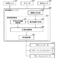
- FIG. 1 is a block diagram showing a schematic configuration of the vehicle control unit 200 according to the first embodiment.
- the vehicle control unit 200 is mounted on the vehicle and is connected to the external world sensor 110, the locator 120, the vehicle sensor 130, the EPS (Electric Power Steering) controller 311, the power train controller 312, and the brake controller 313 provided in the vehicle. There is.
- the vehicle on which the vehicle control unit 200 is mounted is referred to as "own vehicle”.
- the outside world sensor 110 is a sensor that detects the position of obstacles, lane markings, etc. that exist around the vehicle.
- the outside world sensor 110 includes, for example, a front camera that detects the position, angle, and curvature of the road marking line, a radar that acquires the position and speed of the preceding vehicle to be followed by the own vehicle, and the like.
- the outside world sensor 110 may be composed of, for example, LiDAR (Light Detection and Ringing), sonar, vehicle-to-vehicle communication device, road-to-vehicle communication device, and the like.
- the locator 120 is a device that distributes map information of the road on which the vehicle should travel and its surroundings based on the position information and map information of the vehicle.
- a method for the locator 120 to acquire the position information of the own vehicle for example, a method of calculating from a positioning signal received from a GNSS (Global Navigation Satellite System) satellite may be used, or a relative feature of a feature around the own vehicle acquired by LiDAR or the like may be used. It may be a method of calculating from the position and the map information.
- GNSS Global Navigation Satellite System
- the vehicle sensor 130 acquires information on the state of the own vehicle, such as the speed, acceleration, direction, and angular velocity of the own vehicle.
- the vehicle sensor 130 includes, for example, a steering angle sensor, a steering torque sensor, a yaw rate sensor, a speed sensor, an acceleration sensor, and the like.
- the EPS controller 311 and the power train controller 312 and the brake controller 313 control the EPS motor 5, the power train unit 6 and the brake unit 7 so as to realize the target values of the steering angle, the driving force and the braking force of the own vehicle, respectively. It is a controller to do.
- the vehicle control unit 200 is a unit that controls the operation of the vehicle, calculates each target value of the steering angle, the driving force, and the braking force of the own vehicle, and inputs the target values to the EPS controller 311, the power train controller 312, and the brake controller 313. do.
- the vehicle control unit 200 is an integrated circuit such as a microprocessor, and has a memory such as a ROM (Read Only Memory) and a RAM (Random Access Memory) for storing various programs, and a CPU (Central Processing Unit) for executing the program.
- the function of the vehicle control unit 200 is realized by the processor executing the program.
- Specific examples of the vehicle control unit 200 include an advanced driver assistance system electronic control unit (ADAS-ECU). Details of the vehicle control unit 200 will be described later.
- ADAS-ECU advanced driver assistance system electronic control unit
- FIG. 2 is a diagram showing a schematic configuration of own vehicle 1 which is a vehicle equipped with a vehicle control unit 200.
- the own vehicle 1 includes a steering wheel 2, a steering shaft 3, a steering unit 4, an EPS motor 5, a power train unit 6, a brake unit 7, a front camera 111, a radar sensor 112, and a GNSS sensor 121.
- the steering wheel 2 is a so-called steering wheel for the driver to operate the own vehicle 1.
- the steering wheel 2 is coupled to the steering shaft 3, and the steering unit 4 is connected to the steering shaft 3.
- the steering unit 4 rotatably supports the front wheels as steering wheels and is rotatably supported by the vehicle body frame. Therefore, the steering torque generated by the operation of the steering wheel 2 of the driver rotates the steering shaft 3, and the steering unit 4 steers the front wheels to the left and right in accordance with the rotation of the steering shaft 3.
- the driver can control the lateral movement amount of the own vehicle 1 when the own vehicle 1 moves forward or backward.
- the steering shaft 3 can also be rotated by the EPS motor 5.
- the EPS controller 311 can freely steer the front wheels independently of the operation of the steering wheel 2 of the driver.
- the vehicle control unit 200 includes a front camera 111, a radar sensor 112, a GNSS sensor 121, a navigation device 122, a steering angle sensor 131, a steering torque sensor 132, a yaw rate sensor 133, a speed sensor 134, an acceleration sensor 135, an EPS controller 311 and a power.
- the train controller 312 and the brake controller 313 are connected.
- the front camera 111 is installed at a position where the lane marking in front of the vehicle can be detected as an image, and detects the front environment of the own vehicle such as lane information and the position of obstacles based on the image information.
- the radar sensor 112 irradiates the radar and detects the reflected wave to output the relative distance and the relative speed of the obstacle with respect to the own vehicle 1.
- the radar sensor 112 well-known radars such as millimeter-wave radar, LiDAR, laser range finder, and ultrasonic radar can be used.
- the outside world sensor 110 shown in FIG. 1 is composed of the front camera 111 and the radar sensor 112. It is also possible to use the front camera 111 as a means for detecting the relative distance and the relative speed of the obstacle.
- the GNSS sensor 121 receives radio waves from the positioning satellite with an antenna and outputs the absolute position and absolute direction of the own vehicle 1 by performing positioning calculation.
- the navigation device 122 has a function of calculating an optimum travel route for a destination (destination) set by the driver, and stores map data including road information of each road constituting the road network.
- Road information is map node data that expresses road alignment, and each map node data includes absolute position (latitude, longitude, altitude), lane width, road curvature, cant angle, inclination angle information, etc. of each node. ing.
- the locator 120 shown in FIG. 1 is composed of the GNSS sensor 121 and the navigation device 122.
- the steering angle sensor 131 detects the steering angle of the steering wheel 2.
- the steering torque sensor 132 detects the steering torque of the steering shaft 3.
- the yaw rate sensor 133 detects the yaw rate of the own vehicle 1.
- the speed sensor 134 detects the speed of the own vehicle 1.
- the acceleration sensor 135 detects the acceleration of the own vehicle 1.
- the vehicle sensor 130 shown in FIG. 1 is composed of a steering angle sensor 131, a steering torque sensor 132, a yaw rate sensor 133, a speed sensor 134, and an acceleration sensor 135.
- FIG. 2 shows a vehicle whose driving force source is only the engine as an example of the own vehicle 1, but the own vehicle 1 includes an electric vehicle whose driving force source is an electric motor and both an engine and an electric motor. It may be a hybrid vehicle used as a driving force source.
- the vehicle control unit 200 includes a coordinate point generation unit 210 and a vehicle control device 201.
- the coordinate point generation unit 210 has a plurality of positions where the own vehicle should travel based on at least one of the road marking line information obtained from the outside world sensor 110, the position information history of the preceding vehicle, and the map information obtained from the locator 120. Generates point sequence information including a plurality of coordinate points representing. For example, when the vehicle control unit 200 performs lane keeping control of the own vehicle, point sequence information is generated at least based on the road lane marking information, and when the vehicle control unit 200 causes the own vehicle to follow the preceding vehicle, at least. Point sequence information is generated based on the position information history of the preceding vehicle, and when the vehicle control unit 200 travels the own vehicle along the route to the destination, coordinate points are generated at least based on the map information.
- the coordinate point generation unit 210 may generate point sequence information from two or more combinations of road lane marking information, position information history, and map information.
- coordinate points generated by the coordinate point generation unit 210 representing the positions where the vehicle should travel are simply referred to as "coordinate points”, and a plurality of coordinate points generated by the coordinate point generation unit 210.
- the point sequence information including the above is simply referred to as "point sequence information”.
- the vehicle control device 201 includes a reference route generation unit 220, a planned mileage calculation unit 230, a target value calculation unit 240, and a vehicle control unit 250.
- the reference path generation unit 220 calculates the path length (distance traced by the coordinate points in chronological order) from the preset reference point to each coordinate point based on the point sequence information generated by the coordinate point generation unit 210.
- a reference path which is a reference path, is generated by performing a polynomial approximation that approximates a plurality of coordinate points with a polynomial that is a function of the path length from the reference point.
- the reference path generation unit 220 acquires point sequence information including a plurality of coordinate points generated by the coordinate point generation unit 210 (step S221).
- each coordinate point is represented by the own vehicle coordinate system based on the position of the own vehicle.
- a coordinate system in which the position of the own vehicle is the origin, the x-coordinate is taken in the direction toward the front of the own vehicle, and the y-coordinate is taken in the direction toward the side of the own vehicle is defined as the own vehicle coordinate system. do. Therefore, the x-coordinate of each coordinate point (x, y) is referred to as "traveling direction position", and the y-coordinate is referred to as "horizontal position".
- the reference route generation unit 220 sets a reference point as a reference for calculating the route length in the vicinity of the own vehicle position (step S222).
- the position of the reference point is set either on the coordinate points, between the coordinate points, or on an extension of a straight line or a curve connecting the coordinate points.
- FIG. 4 shows an example of a reference point.
- the method of setting the reference point is not limited to this example, and any method may be used.
- intersection of x 0 with a curve obtained by approximating multiple coordinate points with a polynomial function or spline function, or the method of subtracting multiple coordinate points from the vehicle position with a curve approximated by a polynomial function or spline function.
- the intersection with the line may be used as a reference point.
- the reference path generation unit 220 obtains the path length L from the reference point set in step S222 to each coordinate point (step S223).
- the distance obtained by linearly tracing the coordinate points from the reference point is defined as the path length L.
- the definition of the route length L is not limited to this.
- the distance obtained by line-integrating a curve obtained by approximating a plurality of coordinate points with a polynomial function or a spline function may be defined as the path length L.
- the coordinate points are obtained as three-dimensional coordinates including the altitude (elevation)
- the three-dimensional distance following the coordinate points from the reference point may be defined as the path length L.
- the planned mileage calculation unit 230 calculates the planned mileage as a three-dimensional distance.
- the reference route generation unit 220 sets each of the x-coordinate (position in the traveling direction of the own vehicle) and the y-coordinate (position in the lateral direction of the own vehicle) of the plurality of coordinate points to the Mth order (M is 1) which is a function of the route length L.
- M is 1
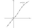
- a polynomial approximation that approximates with the polynomial of the above integers) is performed (step S224). For example, at a plurality of coordinate points illustrated in FIG. 4, the relationship between the route length L and the vehicle traveling direction position x is as shown in FIG. 5, and the relationship between the route length L and the vehicle lateral direction position y is shown in FIG. Will be.
- the reference route generation unit 220 has a polynomial expression f x (L) that approximates the relationship between the route length L and the vehicle traveling direction position x, and a polynomial expression f y that approximates the relationship between the route length L and the vehicle lateral position y. (L) and is obtained.
- the reference route generation unit 220 approximates each of the own vehicle traveling direction position x and the own vehicle lateral direction position y with a cubic polynomial expression.
- the own vehicle traveling direction position x and the own vehicle lateral direction position y are expressed by the following equations 101 and 102, respectively, and the reference route generation unit 220 uses the values of the respective coefficients included in the equations 101 and 102. calculate.
- the point sequence information acquired by the reference route generation unit 220 includes only the x-coordinate (position in the vehicle traveling direction) and the y-coordinate (position in the vehicle lateral direction) of each coordinate point.
- the point sequence information may include other information such as the vehicle speed and yaw rate that the vehicle should take at each coordinate point, the curvature of the road at each coordinate point, the azimuth angle of the road, and the like.
- the reference path generation unit 220 may also approximate the information with a polynomial expression. That is, the reference route generation unit 220 approximates all the information with a polynomial expression according to the content of the point sequence information acquired from the coordinate point generation unit 210 and the parameters for which the vehicle control unit 250 calculates the target value. May be good.
- the target value calculation unit 240 controls the actuator of the own vehicle based on the reference path represented by the polynomial expression generated by the reference route generation unit 220 and the planned mileage of the own vehicle calculated by the planned mileage calculation unit 230. Calculate the target value of each parameter used in. Specifically, the planned mileage calculation unit 230 calculates the target position, which is the target value of the position of the own vehicle after the unit time, and the target azimuth, which is the target value of the azimuth angle of the own vehicle after the unit time. do. Further, the target value calculation unit 240 calculates the target steering angle, which is the target value of the steering angle of the own vehicle after a unit time, from the target position and the target azimuth angle of the own vehicle and the curvature of the road at the target position.
- x-coordinate of the target position of the own vehicle is x-tg and the y-coordinate is y- tg
- x- tg and y- tg are expressed as follows, respectively.
- the target azimuth angle ⁇ tg of the own vehicle and the curvature ⁇ tg of the road can be calculated as follows using a cubic polynomial of x and y.
- the target azimuth angle ⁇ tg of the vehicle and the road may be calculated using a cubic polymorphism as follows.
- the vehicle control unit 250 reduces the error between the position and azimuth angle of the own vehicle at the current time acquired by the vehicle sensor 130 and the target position and target azimuth angle of the own vehicle calculated by the target value calculation unit 240.
- the control target value for the actuator specifically, the target steering angle, the target driving force, and the target braking force are calculated so that the steering angle and speed of the own vehicle become values according to the target curvature of the own vehicle. ..
- the vehicle control unit 250 transmits the target steering angle to the EPS controller 311, transmits the target driving force to the power train controller 312, and transmits the target braking force to the brake controller 313.
- the EPS controller 311 controls the EPS motor 5 so as to realize the target steering angle received from the vehicle control unit 250.
- the powertrain controller 312 controls the powertrain unit 6 so as to realize the target driving force received from the vehicle control unit 250.
- the brake controller 313 controls the brake unit 7 so as to realize the target braking force received from the vehicle control unit 250.
- the EPS controller 311 controls the EPS motor 5 based on the steering torque of the steering wheel 2. Further, in a situation where the driver controls the speed of the own vehicle, the power train controller 312 controls the power train unit 6 based on the amount of depression of the accelerator pedal, and the brake controller 313 controls the power train unit 6 based on the amount of depression of the brake pedal. Controls the brake unit 7.
- the target value calculation unit 240 calculates the target values of the position and azimuth of the own vehicle and the curvature of the road on which the own vehicle travels.
- the reference path generator 220 approximates the yaw rate to be taken by the own vehicle at each coordinate point with a polynomial expression which is a function of the route length from the reference point, and targets the target.
- the value calculation unit 240 may calculate the target yaw rate, which is the target value of the yaw rate of the own vehicle after a unit time, from the polynomial expression and the planned mileage. In that case, the vehicle control unit 250 controls the actuator so that the error between the yaw rate of the own vehicle and the target yaw rate acquired by the vehicle sensor 130 after a unit time becomes small.
- the vehicle control unit 200 has a coordinate point generation unit 210 that generates point sequence information including a plurality of coordinate points representing a plurality of positions to be traveled by the own vehicle, and the point sequence information.
- the vehicle control device 201 which calculates a reference path by polynomially approximating a plurality of coordinate points included in the vehicle, and calculates a target steering angle, a target driving force, and a target braking force for driving the own vehicle along the reference path. To be equipped.
- the vehicle control device 201 calculates the reference path by approximating the plurality of coordinate points to a polynomial expression that is a function of the path length from the reference point, even when the own vehicle makes a 90-degree turn or makes a U-turn, the vehicle control device 201 calculates the reference path. It is possible to accurately express the reference route that the vehicle should travel. As a result, the route followability in the automatic control of the own vehicle is improved.
- the target value calculation unit 230 sets the vehicle speed or the target vehicle speed (Vtg ) of the own vehicle used for calculating the planned mileage of the own vehicle to a negative value.
- 240 can calculate the target position at the time of retreat. Therefore, this embodiment can be applied not only when the own vehicle moves forward but also when the vehicle moves backward.
- the vehicle can be controlled to travel along the forward gaze point, and the occupant of the vehicle can be controlled. It is possible to realize driving that does not give a sense of discomfort.
- the forward gaze point is a point where the driver is expected to gaze when manually driving the own vehicle
- the forward gaze time is defined as the time required for the own vehicle to reach the forward gaze point.
- the EPS controller 311, the power train controller 312, and the brake controller 313 are all connected to the vehicle control unit 200.
- the vehicle control unit 200 controls acceleration / deceleration of the own vehicle. If not, it is not necessary to connect the powertrain controller 312 and the brake controller 313 to the vehicle control unit 200.
- the vehicle control unit 200 is an integrated circuit such as a microprocessor, and is an A / D conversion circuit, a D / A conversion circuit, a processor such as a CPU (Central Processing Unit), a ROM (Read Only Memory), and a RAM. It is equipped with memory such as (RandomAccessMemory).
- the processor of the vehicle control unit 200 processes the information input from the external world sensor 110, the locator 120, and the vehicle sensor 130 according to the program stored in the ROM, thereby processing the above-mentioned coordinate point generation unit 210 and reference path generation unit 220.
- the planned mileage calculation unit 230, the target value calculation unit 240, and the vehicle control unit 250 are realized, and the target steering angle, the target driving force, and the target braking force of the own vehicle are calculated.
- the vehicle control unit 200 acquires point sequence information including information on a plurality of coordinate points on which the vehicle should travel when executed by the processor, and advances the vehicle based on the plurality of coordinate points.
- the planned mileage calculation unit 230 calculates only one planned mileage (Ltg ) of the own vehicle in a unit time, but in the second embodiment, a plurality of unit times having different lengths are calculated. It is used to calculate a plurality of planned mileages corresponding to each of a plurality of unit times. Since the basic configuration and operation of the vehicle control unit 200 of the second embodiment are the same as those of the first embodiment, the description overlapping with the first embodiment will be omitted.
- the planned mileage calculation unit 230 calculates two planned mileages. That is, the planned mileage calculation unit 230 presets the first planned mileage, which is the distance that the own vehicle should travel in the predetermined first unit time, based on the vehicle speed or the target vehicle speed of the own vehicle. The second planned mileage, which is the distance that the own vehicle should travel in the second unit time, is calculated.
- the vehicle speed or target vehicle speed of the own vehicle used for calculating the planned mileage is V tg
- the first unit time is ⁇ t 1
- the second unit time is ⁇ t 2
- the first planned mileage L tg 1 and the second planned travel distance L tg2 of, respectively represented as L tg1 V tg ⁇ t 1
- L tg2 V tg ⁇ t 2.
- the target value calculation unit 240 includes a reference route represented by a polynomial expression generated by the reference route generation unit 220, and the first planned mileage and the second planned mileage of the own vehicle calculated by the planned mileage calculation unit 230. Based on, the target value of the control of the actuator of the own vehicle is calculated. At this time, the target value calculation unit 240 selects and uses either the first planned mileage or the second planned mileage for each parameter to be calculated for the target value.
- planned travel distance calculator 230 the vehicle of the y-coordinate of the target position (target lateral position) y tg and the target azimuth theta tg calculated using the first predetermined travel distance L tg1, curvature of the road ⁇ assuming calculated using the second planned travel distance L tg2 tg, the target lateral position y tg, the curvature kappa tg target azimuth theta tg and roads are respectively calculated as follows.
- the vehicle control unit 250 reduces the error between the position and azimuth angle of the own vehicle at the current time acquired by the vehicle sensor 130 and the target position and target azimuth angle of the own vehicle calculated by the target value calculation unit 240.
- the control target value for the actuator specifically, the target steering angle, the target driving force, and the target braking force are calculated so that the steering angle and speed of the own vehicle become values according to the target curvature of the own vehicle. ..
- the vehicle control unit 250 transmits the target steering angle to the EPS controller 311, transmits the target driving force to the power train controller 312, and transmits the target braking force to the brake controller 313.
- the first unit time ⁇ t 1 is the forward gaze time
- the lateral position and azimuth of the own vehicle are controlled so that the own vehicle travels along the forward gaze point.
- the second unit time ⁇ t 2 is set to 0
- the steering angle of the own vehicle is controlled according to the curvature of the road at the current position of the own vehicle.
- target values at different positions can be set for each parameter, so that control with higher route followability and stability can be performed.
- two planned mileages are used, but three or more are used, and the number of parameters that the vehicle control unit 250 can calculate the target value can be increased at the maximum.
- the target value calculation unit 240 controls the actuator of the own vehicle based on the reference path represented by the polynomial expression generated by the reference route generation unit 220 and the planned mileage of the own vehicle calculated by the planned mileage calculation unit 230. Calculate the target value of. Since the planned mileage L tg is a vector quantity, the target value for controlling the actuator of the own vehicle is also calculated as the vector quantity.
- the target lateral position y tg , the target azimuth angle ⁇ tg, and the target speed V tg of the own vehicle are calculated as follows.
- the vehicle control unit 250 adjusts the dynamics of the vehicle so that the position, azimuth angle, and speed of the own vehicle follow the target values (target values at a plurality of times) at a plurality of points calculated by the target value calculation unit 240.
- a dynamic vehicle model which is a mathematically expressed motion model
- the behavior of the own vehicle is predicted at intervals of the current time 0 to the unit time ⁇ t by N ⁇ ⁇ t, and the desired movement of the own vehicle is obtained.
- the optimum target steering amount or the optimum target steering amount and target acceleration are calculated.
- the predicted vehicle state quantity is N points.
- the vehicle control unit 250 solves the following constrained optimization problem at regular intervals.
- J is an evaluation function
- x is a vehicle state quantity
- u is a control input
- f is a vector value function related to a dynamic vehicle model
- x 0 is an initial value
- g is a vector value function related to a constraint.
- the above optimization problem is treated as a minimization problem, but it can also be treated as a maximization problem by inverting the sign of the evaluation function.
- the above vehicle state quantity x and control input u are set as follows.
- ⁇ is the skid angle
- ⁇ is the yaw rate
- ⁇ is the steering angle
- ⁇ is the steering angular velocity
- ⁇ is the acceleration
- j is the jerk.
- the dynamic vehicle model f uses the following two-wheel model.
- h is a vector value function related to the evaluation item
- h N is a vector value function related to the evaluation item at the end (prediction point N)
- W and W N are weight matrices, which are diagonal matrices having weights for each evaluation item as diagonal components, and can be appropriately changed as parameters.
- the vector value functions h and h N related to the evaluation items are set as follows in order to steer and control the vehicle so as to travel in the center of the lane with a small control input and to make the vehicle speed follow the target vehicle speed.
- evaluation items are set to evaluate the route following error, the angle following error, the steering speed, the vehicle speed following error, and the jerk.
- acceleration and acceleration are set. Jerk and the like may be added to the evaluation items.
- the function g is for setting the vehicle state quantity x and the upper limit value and the lower limit value (hereinafter, also referred to as "upper and lower limit values") of the control input u in the constrained optimization problem, and is optimized. Is executed under the condition of g (x, u) ⁇ 0.
- the upper limit values of the steering speed ⁇ and the jerk j are set to ⁇ , ⁇ j (> 0), and the lower limit values are set to _ ⁇ , _j ( ⁇ 0).
- the function g is set as follows (the symbol "_” means the underscore attached to the character following it, and the symbol " ⁇ ” means the overbar attached to the character following it).
- upper and lower limit values may be set for the direction, yaw rate, acceleration, etc. in order to secure the riding comfort
- upper and lower limit values of the vehicle speed may be set in order to strictly adhere to the speed limit.
- the vehicle control unit 250 calculates the target steering angle and target acceleration of the own vehicle and transmits them to the EPS controller 311, the power train controller 312, and the brake controller 313.
- the vehicle control unit 250 can calculate the target steering angle and the target acceleration with a small accumulation of errors for a plurality of target positions, so that the route followability of the own vehicle is improved. Furthermore, the effect of improving the riding comfort can be obtained by evaluating the yaw rate and the acceleration with the evaluation function.
- FIG. 8 is a block diagram showing the configuration of the vehicle control unit 200 according to the fourth embodiment.
- the configuration of the vehicle control unit 200 of the fourth embodiment is the configuration of the vehicle control device 201 with the calculation result storage unit 260 added to the configuration of FIG.
- the calculation result storage unit 260 stores the calculation result of the vehicle control unit 250. Since other configurations are the same as those of the first to third embodiments, the description overlapping with the first to third embodiments will be omitted.
- the planned mileage calculation unit 230 calculates the planned mileage, which is the distance that the own vehicle should travel in the unit time ⁇ t, using the information of the predicted speed stored in the calculation result storage unit 260. Further, when the present embodiment is applied to the third embodiment, the planned mileage calculation unit 230 uses the speed information stored in the calculation result storage unit 260 to display the speed from the current time to N ⁇ ⁇ t ahead. Calculate the planned mileage for each unit time ⁇ t.
- the planned mileage calculation unit 230 calculates the planned mileage by using the speed calculation result by the vehicle control unit 250, that is, the calculation result of the speed of the own vehicle predicted in the future.
- the vehicle control unit 250 can generate a route that is easier to travel, and the ride quality of the vehicle is improved.
- FIG. 9 is a block diagram showing the configuration of the vehicle control unit 200 according to the fourth embodiment.
- the configuration of the vehicle control unit 200 of the fourth embodiment is almost the same as the configuration of FIG. 1, but the result of polynomial approximation of the speed of the own vehicle is input from the reference route generation unit 220 to the planned mileage calculation unit 230.
- the planned mileage calculation unit 230 calculates the planned mileage, which is the distance that the vehicle should travel in the unit time ⁇ t, by using the polynomial expression of the speed of the own vehicle acquired from the reference route generation unit 220. Since other configurations are the same as those of the first to third embodiments, the description overlapping with the first to third embodiments will be omitted.
- the point sequence information includes the vehicle speed information that the own vehicle should take at each coordinate point
- the reference route generation unit 220 further determines the speed that the own vehicle should take at each coordinate point. , Performs polynomial approximation that approximates with a polynomial that is a function of the path length from the reference point.
- the reference route generation unit 220 approximates the speed that the own vehicle should take with a cubic polynomial expression.
- the speed V that the vehicle should take is represented by the following third-order polynomial expression.
- a simultaneous equation of a cubic polynomial of the speed V calculated by the reference route generation unit 220 and a relational expression L V ⁇ t of the distance L when the vehicle travels at the vehicle speed V for a unit time ⁇ t is obtained. by solving, it calculates the own vehicle will travel distance L tg in a unit time Delta] t.
- the distance when the vehicle travels for a unit time ⁇ t at a speed calculated from a plurality of coordinate points acquired from the coordinate point generation unit 210 is calculated as the planned travel distance Ltg.
- the path followability of is improved.
Landscapes
- Engineering & Computer Science (AREA)
- Automation & Control Theory (AREA)
- Transportation (AREA)
- Mechanical Engineering (AREA)
- Human Computer Interaction (AREA)
- Chemical & Material Sciences (AREA)
- Combustion & Propulsion (AREA)
- Steering Control In Accordance With Driving Conditions (AREA)
- Control Of Driving Devices And Active Controlling Of Vehicle (AREA)
Abstract
車両制御装置(201)において、基準経路生成部(220)は、自車が走行すべき複数の座標点の情報を含む点列情報を取得し、複数の座標点に基づいて、自車の進行方向位置および横方向位置のそれぞれを、予め設定された基準点からの経路長の関数である多項式で近似することで、多項式で表される基準経路を生成する。予定走行距離演算部(230)は、予め定められた長さの単位時間で自車が走行すべき距離である予定走行距離を算出する。目標値演算部(240)は、自車の進行方向位置の多項式、自車の横方向位置の多項式および予定走行距離に基づいて、単位時間後の自車の位置の目標値である目標位置を算出する。車両制御部(250)は、単位時間後の自車の位置と目標位置との誤差が小さくなるように、自車のアクチュエータを制御する。
Description
本開示は、車両の自動運転または運転支援を行う車両制御装置に関する。
例えば下記の特許文献1には、追従対象である先行車の自車に対する相対位置を時刻ごとに記憶し、記憶した一連の相対位置を多項式近似することで自車の経路を算出し、その経路に沿って自車を走行させることによって、自車を先行車に追従させて走行させる車両制御装置が開示されている。
特許文献1の技術では、例えば先行車が交差点で90度旋回(右左折した場合)やUターンしたような場合に、記憶した先行車の相対位置と多項式近似で得た経路との乖離が大きくなり、自車を精度良く先行車に追従させることが困難になる。その場合、自車の走行経路が先行車の走行経路から乖離してしまい、自車の乗員に違和感を与えるおそれがある。
本開示は以上のような課題を解決するためになされたものであり、自車が90度旋回やUターンするような場合にも、自車が走行すべき経路を精度良く算出できる車両制御装置を提供することを目的とする。
本開示に係る車両制御装置は、自車が走行すべき複数の座標点の情報を含む点列情報を取得し、複数の前記座標点に基づいて、前記自車の進行方向位置および横方向位置のそれぞれを、予め設定された基準点からの経路長の関数である多項式で近似することで、前記多項式で表される基準経路を生成する基準経路生成部と、予め定められた長さの単位時間で前記自車が走行すべき距離である予定走行距離を算出する予定走行距離演算部と、前記自車の進行方向位置の多項式、前記自車の横方向位置の多項式および前記予定走行距離に基づいて、前記単位時間後の前記自車の位置の目標値である目標位置を算出する目標値演算部と、前記単位時間後の前記自車の位置と前記目標位置との誤差が小さくなるように、前記自車のアクチュエータを制御する車両制御部と、を備える。
本開示によれば、自車が走行すべき基準経路は、自車の進行方向位置および横方向位置を、基準点からの経路長の関数である多項式に近似することで算出される。そのため、自車が90度旋回やUターンするような場合でも、基準経路を精度よく表現することができる。
本開示の目的、特徴、態様、および利点は、以下の詳細な説明と添付図面とによって、より明白となる。
<実施の形態1>
図1は、実施の形態1に係る車両制御ユニット200の概略構成を示すブロック図である。車両制御ユニット200は車両に搭載されており、当該車両に備えられた外界センサ110、ロケータ120、車両センサ130、EPS(Electric Power Steering)コントローラ311、パワートレインコントローラ312およびブレーキコントローラ313と接続されている。以下、車両制御ユニット200が搭載された車両を「自車」という。
図1は、実施の形態1に係る車両制御ユニット200の概略構成を示すブロック図である。車両制御ユニット200は車両に搭載されており、当該車両に備えられた外界センサ110、ロケータ120、車両センサ130、EPS(Electric Power Steering)コントローラ311、パワートレインコントローラ312およびブレーキコントローラ313と接続されている。以下、車両制御ユニット200が搭載された車両を「自車」という。
外界センサ110は、自車の周辺に存在する障害物や区画線などの位置を検出するセンサである。外界センサ110は、例えば、道路区画線の位置、角度および曲率を検知する前方カメラ、自車が追従する対象とする先行車の位置および速度を取得するレーダなどで構成される。また、外界センサ110は、例えばLiDAR(Light Detection and Ranging)、ソナー、車車間通信装置、路車間通信装置などで構成されてもよい。
ロケータ120は、自車の位置情報と地図情報とに基づいて、自車が走行すべき道路およびその周辺の地図情報を配信する装置である。ロケータ120が自車の位置情報を取得する方法としては、例えばGNSS(Global Navigation Satellite System)衛星から受信した測位信号から算出する方法でもよいし、LiDAR等で取得した自車周辺の地物の相対位置と地図情報とから算出する方法でもよい。
車両センサ130は、自車の速度、加速度、方位、角速度など、自車の状態の情報を取得する。車両センサ130は、例えば、操舵角センサ、操舵トルクセンサ、ヨーレートセンサ、速度センサ、加速度センサなどで構成される。
EPSコントローラ311、パワートレインコントローラ312およびブレーキコントローラ313は、それぞれ自車の操舵角、駆動力および制動力の各目標値を実現するように、EPSモータ5、パワートレインユニット6およびブレーキユニット7を制御するコントローラである。
車両制御ユニット200は、車両の動作を制御するユニットであり、自車の操舵角、駆動力および制動力の各目標値を演算して、EPSコントローラ311、パワートレインコントローラ312およびブレーキコントローラ313に入力する。車両制御ユニット200は、マイクロプロセッサ等の集積回路であり、各種のプログラムを記憶するROM(Read Only Memory)、RAM(Random Access Memory)などのメモリと、プログラムを実行するCPU(Central Processing Unit)などのプロセッサとを備え、プロセッサがプログラムを実行することにより車両制御ユニット200の機能が実現される。車両制御ユニット200の具体例としては、先進運転支援システム電子制御ユニット(ADAS-ECU)などがある。車両制御ユニット200の詳細については後述する。
図2は、車両制御ユニット200を搭載した車両である自車1の概略構成を示す図である。自車1は、ステアリングホイール2と、ステアリング軸3と、操舵ユニット4と、EPSモータ5と、パワートレインユニット6と、ブレーキユニット7と、前方カメラ111と、レーダセンサ112と、GNSSセンサ121と、ナビゲーション装置122と、操舵角センサ131と、操舵トルクセンサ132と、ヨーレートセンサ133と、速度センサ134と、加速度センサ135と、図1に示した車両制御ユニット200、EPSコントローラ311、パワートレインコントローラ312およびブレーキコントローラ313とを備える。
ステアリングホイール2は、ドライバが自車1を操作するための、いわゆるハンドルである。ステアリングホイール2はステアリング軸3に結合されており、ステアリング軸3には操舵ユニット4が連接されている。操舵ユニット4は、操舵輪としての前輪を回動自在に支持すると共に、車体フレームに転舵自在に支持されている。従って、ドライバのステアリングホイール2の操作によって発生した操舵トルクはステアリング軸3を回転させ、ステアリング軸3の回転に応じて操舵ユニット4が前輪を左右方向へ転舵させる。これによって、ドライバは自車1が前進または後進する際の自車1の横移動量を操作することができる。
なお、ステアリング軸3はEPSモータ5によって回転させることも可能である。EPSコントローラ311は、EPSモータ5に流れる電流を制御することで、ドライバのステアリングホイール2の操作と独立して、前輪を自在に転舵させることができる。
車両制御ユニット200には、前方カメラ111、レーダセンサ112、GNSSセンサ121、ナビゲーション装置122、操舵角センサ131、操舵トルクセンサ132、ヨーレートセンサ133、速度センサ134、加速度センサ135、EPSコントローラ311、パワートレインコントローラ312、ブレーキコントローラ313が接続されている。
前方カメラ111は、車両前方の区画線が画像として検出できる位置に設置され、画像情報を基に、車線情報や障害物の位置などの自車の前方環境を検出する。ここでは、前方環境を検出する前方カメラのみを示しているが、後方や側方の環境を検出するカメラも自車1に設置されてもよい。レーダセンサ112は、レーダを照射し、その反射波を検出することで、自車1を基準にした障害物の相対距離および相対速度を出力する。レーダセンサ112としては、ミリ波レーダ、LiDAR、レーザーレンジファインダ、超音波レーダなど周知のものを用いることができる。ここでは、図1に示した外界センサ110は、前方カメラ111およびレーダセンサ112により構成されるものとする。なお、前方カメラ111を、障害物の相対距離と相対速度を検出する手段として用いることも可能である。
GNSSセンサ121は測位衛星からの電波をアンテナで受信し、測位演算することによって自車1の絶対位置および絶対方位を出力する。ナビゲーション装置122は、ドライバが設定した行き先(目的地)に対する最適な走行ルートを演算する機能を有し、道路網を構成する各道路の道路情報を含む地図データを記憶している。道路情報は、道路線形を表現する地図ノードデータであり、各地図ノードデータには各ノードの絶対位置(緯度、経度、標高)、車線幅、道路曲率、カント角、傾斜角情報などが含まれている。ここでは、図1に示したロケータ120は、GNSSセンサ121およびナビゲーション装置122により構成されるものとする。
操舵角センサ131は、ステアリングホイール2の操舵角を検出する。操舵トルクセンサ132は、ステアリング軸3の操舵トルクを検出する。ヨーレートセンサ133は、自車1のヨーレートを検出する。速度センサ134は、自車1の速度を検出する。加速度センサ135は、自車1の加速度を検出する。ここでは、図1に示した車両センサ130は、操舵角センサ131、操舵トルクセンサ132、ヨーレートセンサ133、速度センサ134および加速度センサ135により構成されるものとする。
図2には、自車1の例として、エンジンのみを駆動力源とする車両を示したが、自車1は、電動モータを駆動力源とする電気自動車や、エンジンと電動モータの両方を駆動力源とするハイブリッド車などでもよい。
図1に戻り、実施の形態1に係る車両制御ユニット200の詳細について説明する。図1に示すように、車両制御ユニット200は、座標点生成部210と車両制御装置201と備えている。
座標点生成部210は、外界センサ110から得られる道路区画線情報および先行車の位置情報履歴、ならびにロケータ120から得られる地図情報の少なくとも1つに基づいて、自車が走行すべき複数の位置を表す複数の座標点を含む点列情報を生成する。例えば、車両制御ユニット200が自車の車線維持制御を行う場合は、少なくとも道路区画線情報に基づいて点列情報が生成され、車両制御ユニット200が自車を先行車に追従させる場合は、少なくとも先行車の位置情報履歴に基づいて点列情報が生成され、車両制御ユニット200が自車を目的地までの経路に沿って走行させる場合は、少なくとも地図情報に基づいて座標点が生成される。座標点生成部210は、道路区画線情報、位置情報履歴および地図情報の2つ以上の組み合わせから、点列情報を生成してもよい。
以下、説明の簡略化のため、座標点生成部210が生成した自車が走行すべき位置を表す座標点を、単に「座標点」といい、座標点生成部210が生成した複数の座標点を含む点列情報を、単に「点列情報」というものとする。
車両制御装置201は、基準経路生成部220、予定走行距離演算部230、目標値演算部240および車両制御部250を備えている。
基準経路生成部220は、座標点生成部210が生成した点列情報に基づいて、予め設定された基準点から各座標点までの経路長(座標点を時系列順に辿った距離)を算出し、複数の座標点を、基準点からの経路長の関数である多項式で近似する多項式近似を行うことで、基準となる経路である基準経路を生成する。
基準経路生成部220の動作を、図3のフローチャートを参照しつつ説明する。まず、基準経路生成部220は、座標点生成部210が生成した複数の座標点を含む点列情報を取得する(ステップS221)。本実施の形態では、各座標点は、自車の位置を基準とする自車座標系で表されるものする。ここでは、図4のように、自車位置を原点とし、自車の正面前方へ向かう方向にx座標、自車の真横へ向かう方向にy座標をとった座標系を自車座標系として定義する。そのため、各座標点(x,y)のx座標を「進行方向位置」、y座標を「横方向位置」という。
次に、基準経路生成部220は、自車位置の近傍に、経路長を計算するための基準となる基準点を設定する(ステップS222)。基準点の位置は、座標点上、もしくは座標点の間、もしくは座標点間を結ぶ直線または曲線の延長線上、のいずれかに設定される。図4に基準点の例を示す。図4では、x≧0を満たす最小のx座標を持つ座標点とx<0を満たす最大のx座標を持つ座標点とを結ぶ直線と、x=0の直線との交点に基準点が設定されている。基準点の設定方法はこの例に限られず、任意の方法でよい。例えば、複数の座標点を多項式関数やスプライン関数で近似した曲線とx=0との交点や、複数の座標点を多項式関数やスプライン関数で近似した曲線と自車位置からその曲線へ引いた法線との交点などを、基準点としてもよい。
続いて、基準経路生成部220は、ステップS222で設定した基準点から各座標点までの経路長Lを求める(ステップS223)。本実施の形態では、基準点から座標点を直線的に辿った距離を経路長Lとする。ただし、経路長Lの定義はこれに限られない。例えば、複数の座標点を多項式関数やスプライン関数で近似した曲線を線積分して得られる距離を経路長Lとして定義してもよい。また、座標点が高度(標高)を含む3次元座標として得られる場合、基準点から座標点を辿った3次元の距離を経路長Lと定義してもよい。その場合、予定走行距離演算部230は、予定走行距離を3次元の距離として算出する。
そして、基準経路生成部220は、複数の座標点のx座標(自車進行方向位置)およびy座標(自車横方向位置)のそれぞれを、経路長Lの関数であるM次(Mは1以上の整数)の多項式で近似する多項式近似を実施する(ステップS224)。例えば図4に例示した複数の座標点において、経路長Lと自車進行方向位置xとの関係は図5のようになり、経路長Lと自車横方向位置yとの関係は図6のようになる。基準経路生成部220は、経路長Lと自車進行方向位置xとの関係を近似した多項式fx(L)と、経路長Lと自車横方向位置yとの関係を近似した多項式fy(L)とを求める。
本実施の形態では、基準経路生成部220が、自車進行方向位置xおよび自車横方向位置yのそれぞれを3次多項式で近似するものとする。この場合、自車進行方向位置xおよび自車横方向位置yは、それぞれ次の式101および式102で表現され、基準経路生成部220は、式101および式102に含まれる各係数の値を算出する。
本実施の形態では、基準経路生成部220が取得する点列情報には、各座標点のx座標(自車進行方向位置)およびy座標(自車横方向位置)だけが含まれるものとするが、点列情報には、それ以外の情報、例えば、各座標点で自車がとるべき車速およびヨーレート、各座標点における道路の曲率、道路の方位角などが含まれていてもよい。点列情報がそれらの情報を含む場合、基準経路生成部220は、それらの情報も多項式で近似してもよい。つまり、基準経路生成部220は、座標点生成部210から取得される点列情報の内容、および車両制御部250が目標値算出の対象とするパラメータに応じて、あらゆる情報を多項式で近似してもよい。
予定走行距離演算部230は、自車の車速もしくは目標車速の片方または両方に基づいて、予め定められた単位時間で自車が走行すべき距離である予定走行距離を算出する。予定走行距離の演算に用いる自車の車速もしくは目標車速をVtgとし、単位時間をΔtとすると、単位時間での自車の予定走行距離Ltgは、Ltg=VtgΔtと表される。
目標値演算部240は、基準経路生成部220が生成した多項式で表された基準経路と、予定走行距離演算部230が算出した自車の予定走行距離とに基づいて、自車のアクチュエータの制御に用いる各パラメータの目標値を演算する。具体的には、予定走行距離演算部230は、単位時間後の自車の位置の目標値である目標位置と、単位時間後の自車の方位角の目標値である目標方位角とを算出する。また、目標値演算部240は、自車の目標位置および目標方位角と、目標位置における道路の曲率とから、単位時間後の自車の操舵角の目標値である目標操舵角を算出する。
図7に示すように、自車の目標位置のx座標をxtg、y座標をytgとすると、xtgおよびytgは、それぞれ次のように表される。
このとき、目標とする自車の方位角θtgおよび道路の曲率κtgは、x,yの3次多項式を用いて、次のように計算できる。


なお、点列情報に、座標点のそれぞれで自車がとるべき方位角、および座標点のそれぞれにおける道路の曲率の情報が含まれる場合は、目標とする自車の方位角θtgおよび道路の曲率κtgを、3次多項式を用いて以下のように計算してもよい。
車両制御部250は、車両センサ130で取得される現時刻での自車の位置および方位角と目標値演算部240が算出した自車の目標位置および目標方位角との誤差が小さくなるよう、また、自車の操舵角および速度が自車の目標曲率に応じた値となるように、アクチュエータへの制御目標値、具体的には、目標操舵角、目標駆動力および目標制動力を算出する。そして、車両制御部250は、EPSコントローラ311に目標操舵角を送信し、パワートレインコントローラ312に目標駆動力を送信し、ブレーキコントローラ313に目標制動力を送信する。
EPSコントローラ311は、車両制御部250から受信した目標操舵角を実現するように、EPSモータ5を制御する。パワートレインコントローラ312は、車両制御部250から受信した目標駆動力を実現するように、パワートレインユニット6を制御する。ブレーキコントローラ313は、車両制御部250から受信した目標制動力を実現するように、ブレーキユニット7を制御する。その結果、自車は、式101および式102で表される基準経路に沿って走行するように制御される。
なお、自車の操舵制御をドライバが行っている状況では、EPSコントローラ311は、ステアリングホイール2の操舵トルクに基づいてEPSモータ5を制御する。また、自車の速度制御をドライバが行っている状況では、パワートレインコントローラ312は、アクセルペダルの踏み込み量に基づいてパワートレインユニット6を制御し、ブレーキコントローラ313は、ブレーキペダル踏み込み量に基づいてブレーキユニット7を制御する。
上の説明では、目標値演算部240が、自車の位置および方位角の目標値と、自車が走行する道路の曲率とを算出するものとしたが、例えば、点列情報に各座標点で自車がとるべきヨーレートの情報が含まれている場合、基準経路生成部220が、各座標点で自車がとるべきヨーレートを基準点からの経路長の関数である多項式で近似し、目標値演算部240が、その多項式と予定走行距離とから、単位時間後の自車のヨーレートの目標値である目標ヨーレートを算出してもよい。その場合、車両制御部250は、単位時間後に車両センサ130で取得される自車のヨーレートと目標ヨーレートとの誤差が小さくなるように、アクチュエータの制御を行う。
以上のように、実施の形態1に係る車両制御ユニット200は、自車の走行すべき複数の位置を表す複数の座標点を含む点列情報を生成する座標点生成部210と、点列情報に含まれる複数の座標点を多項式近似することで基準経路を算出し、自車を基準経路に沿って走行させるための目標操舵角、目標駆動力および目標制動力を算出する車両制御装置201とを備える。車両制御装置201は、複数の座標点を、基準点からの経路長の関数である多項式に近似することで基準経路を算出するため、自車が90度旋回やUターンするような場合でも、自車が走行すべき基準経路を精度よく表現することができる。それにより、自車の自動制御における経路追従性が向上する。
なお、車両が後退する場合は、予定走行距離演算部230が自車の予定走行距離の算出に用いる自車の車速もしくは目標車速(Vtg)を負の値にすることで、目標値演算部240は後退時の目標位置を算出することができる。そのため、本実施の形態は、自車が前進するときだけでなく後退するときにも適用可能である。
また、予定走行距離演算部230が予定走行距離を算出に用いる単位時間(Δt)を、前方注視時間とすれば、自車が前方注視点に沿って走行するように制御でき、自車の乗員に違和感を与えない走行を実現できる。ここで、前方注視点は、ドライバが自車を手動運転するときに注視すると想定される地点であり、前方注視時間は、自車が前方注視点に到達するまでに要する時間として定義される。
本実施の形態では、EPSコントローラ311、パワートレインコントローラ312およびブレーキコントローラ313の全てが車両制御ユニット200に接続される構成を示したが、例えば、車両制御ユニット200で自車の加減速制御を行わない場合は、車両制御ユニット200にパワートレインコントローラ312およびブレーキコントローラ313が接続される必要はない。
上述したように、車両制御ユニット200は、マイクロプロセッサ等の集積回路であり、A/D変換回路、D/A変換回路、CPU(Central Processing Unit)などのプロセッサ、ROM(Read Only Memory)、RAM(Random Access Memory)などのメモリ等を備える。車両制御ユニット200のプロセッサは、外界センサ110、ロケータ120および車両センサ130から入力された情報を、ROMに格納されたプログラムに従って処理することで、上記した座標点生成部210、基準経路生成部220、予定走行距離演算部230、目標値演算部240および車両制御部250の各機能を実現し、自車の目標操舵角、目標駆動力および目標制動力を算出する。
言い換えれば、車両制御ユニット200は、プロセッサにより実行されるときに、自車が走行すべき複数の座標点の情報を含む点列情報を取得し、複数の座標点に基づいて、自車の進行方向位置および横方向位置のそれぞれを、予め設定された基準点からの経路長の関数である多項式で近似することで、多項式で表される基準経路を生成する処理と、予め定められた長さの単位時間で自車が走行すべき距離である予定走行距離を算出する処理と、自車の進行方向位置の多項式、自車の横方向位置の多項式および予定走行距離に基づいて、単位時間後の自車の位置の目標値である目標位置を算出する処理と、単位時間後の自車の位置と目標位置との誤差が小さくなるように、自車のアクチュエータを制御する処理と、が結果的に実行されることになるプログラムを格納するためのメモリを備える。このプログラムは、車両制御ユニット200の構成要素の動作の手順や方法をコンピュータに実行させるものであるともいえる。
<実施の形態2>
実施の形態1では、予定走行距離演算部230が単位時間での自車の予定走行距離(Ltg)を1つだけ算出したが、実施の形態2では、長さの異なる複数の単位時間を用いて、複数の単位時間のそれぞれに対応する複数の予定走行距離を算出する。実施の形態2の車両制御ユニット200の基本的な構成および動作は、実施の形態1と同様であるため、実施の形態1と重複する説明は省略する。
実施の形態1では、予定走行距離演算部230が単位時間での自車の予定走行距離(Ltg)を1つだけ算出したが、実施の形態2では、長さの異なる複数の単位時間を用いて、複数の単位時間のそれぞれに対応する複数の予定走行距離を算出する。実施の形態2の車両制御ユニット200の基本的な構成および動作は、実施の形態1と同様であるため、実施の形態1と重複する説明は省略する。
ここでは、予定走行距離演算部230が2つの予定走行距離を算出する例を示す。すなわち、予定走行距離演算部230は、自車の車速もしくは目標車速に基づいて、予め定められた第1の単位時間で自車が走行すべき距離である第1の予定走行距離と、予め定められた第2の単位時間で自車が走行すべき距離である第2の予定走行距離とを算出する。予定走行距離の演算に用いる自車の車速もしくは目標車速をVtgとし、第1の単位時間をΔt1、第2の単位時間をΔt2とすると、第1の予定走行距離Ltg1および第2の予定走行距離Ltg2は、それぞれLtg1=VtgΔt1、Ltg2=VtgΔt2と表される。
目標値演算部240は、基準経路生成部220が生成した多項式で表された基準経路と、予定走行距離演算部230が算出した自車の第1の予定走行距離および第2の予定走行距離とに基づいて、自車のアクチュエータの制御の目標値を演算する。このとき、目標値演算部240は、目標値算出の対象とするパラメータごとに、第1の予定走行距離または第2の予定走行距離のいずれかを選択して用いる。
例えば、予定走行距離演算部230が、自車の目標位置のy座標(目標横位置)ytgおよび目標方位角θtgを第1の予定走行距離Ltg1を用いて算出し、道路の曲率κtgを第2の予定走行距離Ltg2を用いて算出すると仮定すると、目標横位置ytg、目標方位角θtgおよび道路の曲率κtgはそれぞれ次のように計算される。


車両制御部250は、車両センサ130で取得される現時刻での自車の位置および方位角と目標値演算部240が算出した自車の目標位置および目標方位角との誤差が小さくなるよう、また、自車の操舵角および速度が自車の目標曲率に応じた値となるように、アクチュエータへの制御目標値、具体的には、目標操舵角、目標駆動力および目標制動力を算出する。そして、車両制御部250は、EPSコントローラ311に目標操舵角を送信し、パワートレインコントローラ312に目標駆動力を送信し、ブレーキコントローラ313に目標制動力を送信する。
例えば、第1の単位時間Δt1を前方注視時間とすれば、自車の横位置および方位角は、自車が前方注視点に沿って走行するように制御される。また、第2の単位時間Δt2を0とすれば、自車の操舵角が、自車の現在位置における道路の曲率に応じて制御されるようになる。
実施の形態2によれば、自車の予定走行距離を複数用いることで、パラメータごとに異なる位置での目標値を設定できるため、経路追従性および安定性のより高い制御を行うことができる。本実施の形態では、2つの予定走行距離を用いたが、3つ以上でもよく、最大で車両制御部250が目標値算出の対象とするパラメータの数まで増やすことができる。
<実施の形態3>
実施の形態3では、予定走行距離演算部230が、単位時間Δt[秒]ごとの自車の予定走行距離Ltgを、現在時刻からN・Δt[秒]先の時刻までについて算出する。つまり、予定走行距離演算部230は、現在時刻から単位時間Δt[秒]ごとの複数の時刻のそれぞれに対応する複数の予定走行距離Ltgを算出する。予定走行距離の演算に用いる自車の車速もしくは目標車速をVtgとすると、予定走行距離LtgはLtg=VtgTi(i=0,…,N)と表されるベクトル量となる。
実施の形態3では、予定走行距離演算部230が、単位時間Δt[秒]ごとの自車の予定走行距離Ltgを、現在時刻からN・Δt[秒]先の時刻までについて算出する。つまり、予定走行距離演算部230は、現在時刻から単位時間Δt[秒]ごとの複数の時刻のそれぞれに対応する複数の予定走行距離Ltgを算出する。予定走行距離の演算に用いる自車の車速もしくは目標車速をVtgとすると、予定走行距離LtgはLtg=VtgTi(i=0,…,N)と表されるベクトル量となる。
目標値演算部240は、基準経路生成部220が生成した多項式で表された基準経路と、予定走行距離演算部230が算出した自車の予定走行距離とに基づいて、自車のアクチュエータの制御の目標値を演算する。予定走行距離Ltgがベクトル量であるため、自車のアクチュエータの制御の目標値もベクトル量として演算される。自車の目標横位置ytg、目標方位角θtgおよび目標速度Vtgは、それぞれ次のように計算される。
車両制御部250は、自車の位置および方位角ならびに速度が、目標値演算部240で演算された複数地点での目標値(複数時刻での目標値)に追従するように、車両のダイナミクスを数学的に表した運動モデルである動的車両モデルを用いて、現在の時刻0から単位時間Δtの間隔で、N・Δtだけ先までの自車の挙動を予測し、自車の望ましい動作を表現する評価関数を最小化する制御入力uを求める最適化問題を一定期間ごとに解くことで、最適な目標操舵量、あるいは、最適な目標操舵量および目標加速度を演算する。このとき、予測する車両状態量はN点となる。
本実施の形態では、車両制御部250が、以下の制約付き最適化問題を一定期間ごとに解く。

ここで、Jは評価関数、xは車両状態量、uは制御入力、fは動的車両モデルに関するベクトル値関数、x0は初期値、gは制約に関するベクトル値関数である。なお、本実施の形態では上記の最適化問題を最小化問題として扱っているが、評価関数の符号を反転させることで最大化問題として扱うこともできる。
上記の車両状態量xと制御入力uは次のように設定される。
ここで、βは横滑り角、γはヨーレート、δは舵角、ωは舵角速度、αは加速度、jは躍度である。このとき、制御入力uとアクチュエータ制御部(EPSコントローラ311、パワートレインコントローラ312およびブレーキコントローラ313)の制御量を一致させる必要はない。これにより、アクチュエータ制御部の制御量に依存せずに車両状態量xと制御入力uとを設定できる。そして、舵角ではなく舵角速度を制御入力とすることで、評価関数や制約の設定次第で舵角の変動の大きさを容易に制限でき、乗り心地が向上する。同様に、加速度ではなく躍度を制御入力とすることで、評価関数や制約の設定次第で加速度の変動の大きさを容易に制限でき、車両の乗り心地が向上する。
動的車両モデルfは次に示す二輪モデルを用いる。

なお、モデルをコンパクトにするために、x=[Xc,Yc,θ,β,γ,V]T,u=[δ,α]Tとしてもよい。
本実施の形態では、評価関数Jには次式を用いる。

ここで、xkは予測点k(k=0,…,N)における車両状態量、ukは予測点k(k=0,…,N-1)における制御入力である。hは評価項目に関するベクトル値関数、hNは終端(予測点N)における評価項目に関するベクトル値関数、rkは予測点k(k=0,…,N)における目標値である。W,WNは重み行列で、各評価項目に対する重みを対角成分に有する対角行列であり、パラメータとして適宜変更可能である。
小さな制御入力で車両が車線中央を走行するように操舵制御し、車速を目標車速に追従させるために、評価項目に関するベクトル値関数h,hNを次のように設定する。
ここで、eY,k,eθ,k,eV,kはそれぞれ、予測点k(k=0,…,N)における目標経路、目標方位角、目標車速に対する追従誤差(予測値と目標値との差)である。経路追従誤差eY,kは、eY,k=Yc,k-ytg,kと表され、角度追従誤差eθ,kは、eθ,k=θk-θtg,kと表され、車速追従誤差eV,kは、eV,k=Vk-Vtg,kと表される。そして、経路追従誤差eY,kと、角度追従誤差eθ,kと、操舵速度ωkと、車速追従誤差eV,kと躍度jkとが小さくなるように、目標値rk,rNを次のように設定する。
なお、本実施の形態では、経路追従誤差と角度追従誤差と操舵速度と車速追従誤差と躍度とを評価するように評価項目を設定したが、車両の乗り心地を向上させるために、加速度やヨーレートなどを評価項目に加えてもよい。
次に、制約に関するベクトル値関数gについて説明する。関数gは、制約付き最適化問題において、車両状態量xと、制御入力uの上限値および下限値(以下「上下限値」ということもある)とを設定するためのものであり、最適化はg(x,u)≦0の条件のもと実行される。
本実施の形態では、一定範囲内の制御入力で動作するために、操舵速度ω、躍度jの上限値を ̄ω, ̄j(>0)、下限値を_ω,_j(<0)として、関数gを以下のように設定する(記号「_」はそれに続く文字に付されたアンダーバーを意味し、記号「 ̄」はそれに続く文字に付されたオーバーバーを意味している)。

操舵速度ω、躍度jの上下限値を設定することで、乗り心地を確保した車両制御を行うことができる。なお、乗り心地を確保するために、方位、ヨーレート、加速度などに上下限値を設定したり、制限速度を厳守するために、車速の上下限値を設定したりしてもよい。
車両制御部250は、以上の制約付き最適化問題を解くことにより、自車の目標操舵角、目標加速度を演算し、EPSコントローラ311、パワートレインコントローラ312、ブレーキコントローラ313に送信する。
実施の形態3によれば、車両制御部250は、複数の目標位置に対して誤差の累積が小さい目標操舵角、目標加速度を演算することができるため、自車の経路追従性が向上する。さらに、ヨーレートや加速度を評価関数で評価することで乗り心地が向上するという効果も得られる。
<実施の形態4>
図8は、実施の形態4に係る車両制御ユニット200の構成を示すブロック図である。実施の形態4の車両制御ユニット200の構成は、図1の構成に対し、車両制御装置201に演算結果記憶部260を追加したものである。演算結果記憶部260は、車両制御部250の演算結果を記憶する。その他の構成は、実施の形態1~3と同様であるため、実施の形態1~3と重複する説明は省略する。
図8は、実施の形態4に係る車両制御ユニット200の構成を示すブロック図である。実施の形態4の車両制御ユニット200の構成は、図1の構成に対し、車両制御装置201に演算結果記憶部260を追加したものである。演算結果記憶部260は、車両制御部250の演算結果を記憶する。その他の構成は、実施の形態1~3と同様であるため、実施の形態1~3と重複する説明は省略する。
演算結果記憶部260は、車両制御部250の速度に関する演算結果を記憶する。具体的には、単位時間後の自車の位置、方位角および操舵角とそれらの目標値との誤差を求める際に計算した自車の予測速度の情報が、演算結果記憶部260に記憶される。演算結果記憶部260に記憶される予測速度の情報は、任意の時刻の速度(Vk)でもよいし、速度の時系列情報(Vi(i=1,…,N))でもよい。
予定走行距離演算部230は、演算結果記憶部260に記憶された予測速度の情報を用いて、単位時間Δtで自車が走行すべき距離である予定走行距離を演算する。また、本実施の形態を実施の形態3に適用した場合、予定走行距離演算部230は、演算結果記憶部260に記憶された速度の情報を用いて、現在時刻からN・Δt先までの、単位時間Δtごとの予定走行距離を演算する。
実施の形態4によれば、予定走行距離演算部230が、車両制御部250による速度の演算結果、つまり将来予測される自車の速度の演算結果を利用して、予定走行距離を算出する。その結果、車両制御部250において、より走行しやすい経路が生成されるようになり、車両の乗り心地が向上する。
<実施の形態5>
図9は、実施の形態4に係る車両制御ユニット200の構成を示すブロック図である。実施の形態4の車両制御ユニット200の構成は、図1の構成とほぼ同じであるが、基準経路生成部220から予定走行距離演算部230へ、自車の速度を多項式近似した結果が入力される。予定走行距離演算部230は、基準経路生成部220から取得した自車の速度の多項式を利用して、単位時間Δtで自車が走行すべき距離である予定走行距離を算出する。その他の構成は、実施の形態1~3と同様であるため、実施の形態1~3と重複する説明は省略する。
図9は、実施の形態4に係る車両制御ユニット200の構成を示すブロック図である。実施の形態4の車両制御ユニット200の構成は、図1の構成とほぼ同じであるが、基準経路生成部220から予定走行距離演算部230へ、自車の速度を多項式近似した結果が入力される。予定走行距離演算部230は、基準経路生成部220から取得した自車の速度の多項式を利用して、単位時間Δtで自車が走行すべき距離である予定走行距離を算出する。その他の構成は、実施の形態1~3と同様であるため、実施の形態1~3と重複する説明は省略する。
実施の形態5では、点列情報に各座標点で自車がとるべき車速の情報が含まれているものとし、基準経路生成部220は、さらに、各座標点で自車がとるべき速度を、基準点からの経路長の関数である多項式で近似する多項式近似を行う。ここでは、基準経路生成部220は、自車がとるべき速度を3次多項式で近似するものとする。この場合、自車がとるべき速度Vは次の3次多項式で表現される。
予定走行距離演算部230では、基準経路生成部220が算出した速度Vの3次多項式と、車両が車速Vで単位時間Δtだけ走行したときの距離Lの関係式L=VΔtとの連立方程式を解くことで、単位時間Δtでの自車の予定走行距離Ltgを演算する。
実施の形態5によれば、座標点生成部210から取得した複数の座標点から算出される速度で単位時間Δtだけ走行したときの距離が、予定走行距離Ltgとして算出されるため、自車の経路追従性が向上する。
なお、各実施の形態を自由に組み合わせたり、各実施の形態を適宜、変形、省略したりすることが可能である。
上記した説明は、すべての態様において、例示であって、例示されていない無数の変形例が想定され得るものと解される。
1 自車、2 ステアリングホイール、3 ステアリング軸、4 操舵ユニット、5 EPSモータ、6 パワートレインユニット、7 ブレーキユニット、50 処理回路、51 プロセッサ、52 メモリ、110 外界センサ、111 前方カメラ、112 レーダセンサ、121 GNSSセンサ、122 ナビゲーション装置、131 操舵角センサ、132 操舵トルクセンサ、133 ヨーレートセンサ、134 速度センサ、135 加速度センサ、120 ロケータ、130 車両センサ、200 車両制御ユニット、201 車両制御装置、210 座標点生成部、220 基準経路生成部、230 予定走行距離演算部、240 目標値演算部、250 車両制御部、260 演算結果記憶部、311 EPSコントローラ、312 パワートレインコントローラ、313 ブレーキコントローラ。
Claims (10)
- 自車が走行すべき複数の座標点の情報を含む点列情報を取得し、複数の前記座標点に基づいて、前記自車の進行方向位置および横方向位置のそれぞれを、予め設定された基準点からの経路長の関数である多項式で近似することで、前記多項式で表される基準経路を生成する基準経路生成部と、
予め定められた長さの単位時間で前記自車が走行すべき距離である予定走行距離を算出する予定走行距離演算部と、
前記自車の進行方向位置の多項式、前記自車の横方向位置の多項式および前記予定走行距離に基づいて、前記単位時間後の前記自車の位置の目標値である目標位置を算出する目標値演算部と、
前記単位時間後の前記自車の位置と前記目標位置との誤差が小さくなるように、前記自車のアクチュエータを制御する車両制御部と、
を備える車両制御装置。 - 前記予定走行距離演算部は、現在時刻から前記単位時間ごとの複数の時刻のそれぞれに対応する複数の前記予定走行距離を算出し、
前記目標値演算部は、前記複数の前記予定走行距離に基づいて、前記複数の時刻のそれぞれに対応する複数の前記目標位置を算出し、
前記車両制御部は、前記自車の運動モデルを用いて計算した前記複数の時刻のそれぞれに対応する前記自車の位置と前記複数の時刻のそれぞれに対応する複数の前記目標位置との誤差の累積が小さくなるように、前記自車のアクチュエータを制御する、
請求項1に記載の車両制御装置。 - 前記予定走行距離演算部は、前記自車の速度もしくは目標速度の少なくとも片方に基づいて、前記予定走行距離を算出する、
請求項1または請求項2に記載の車両制御装置。 - 前記車両制御部が前記単位時間後の前記自車の位置と前記目標位置との誤差を求める際に計算された前記自車の予測速度に関する情報を記憶する演算結果記憶部をさらに備え、
前記予定走行距離演算部は、前記演算結果記憶部に記憶された情報に基づいて、前記予定走行距離を算出する、
請求項1または請求項2に記載の車両制御装置。 - 前記点列情報には、複数の前記座標点のそれぞれで前記自車がとるべき速度の情報が含まれており、
前記基準経路生成部は、さらに、複数の前記座標点のそれぞれで前記自車がとるべき速度を、前記基準点からの経路長の関数である多項式で近似し、
前記予定走行距離演算部は、前記自車がとるべき速度の多項式に基づいて、前記予定走行距離を算出する、
請求項1または請求項2に記載の車両制御装置。 - 前記点列情報には、複数の前記座標点のそれぞれで前記自車がとるべき方位角の情報が含まれており、
前記基準経路生成部は、さらに、複数の前記座標点のそれぞれで前記自車がとるべき方位角を、前記基準点からの経路長の関数である多項式で近似し、
前記目標値演算部は、さらに、前記自車がとるべき方位角の多項式および前記予定走行距離に基づいて、前記単位時間後の前記自車の方位角の目標値である目標方位角を算出し、
前記車両制御部は、さらに、前記単位時間後の前記自車の方位角と前記目標方位角との誤差が小さくなるように、前記自車のアクチュエータを制御する、
請求項1から請求項5のいずれか一項に記載の車両制御装置。 - 前記点列情報には、複数の前記座標点のそれぞれにおける道路の曲率の情報が含まれており、
前記基準経路生成部は、さらに、複数の前記座標点のそれぞれにおける前記道路の曲率を、前記基準点からの経路長の関数である多項式で近似し、
前記目標値演算部は、さらに、前記道路の曲率の多項式および前記予定走行距離に基づいて、前記単位時間後の前記自車の操舵角の目標値である目標操舵角を算出し、
前記車両制御部は、さらに、前記単位時間後の前記自車の操舵角と前記目標操舵角との誤差が小さくなるように、前記自車のアクチュエータを制御する、
請求項1から請求項6のいずれか一項に記載の車両制御装置。 - 前記点列情報には、複数の前記座標点のそれぞれで前記自車がとるべきヨーレートの情報が含まれており、
前記基準経路生成部は、さらに、複数の前記座標点のそれぞれで前記自車がとるべきヨーレートを、前記基準点からの経路長の関数である多項式で近似し、
前記目標値演算部は、さらに、前記自車がとるべきヨーレートの多項式および前記予定走行距離に基づいて、前記単位時間後の前記自車のヨーレートの目標値である目標ヨーレートを算出し、
前記車両制御部は、さらに、前記単位時間後の前記自車のヨーレートと前記目標ヨーレートとの誤差が小さくなるように、前記自車のアクチュエータを制御する、
請求項1から請求項7のいずれか一項に記載の車両制御装置。 - 前記予定走行距離演算部は、長さの異なる複数の前記単位時間のそれぞれに対応する複数の前記予定走行距離を算出し、
前記目標値演算部は、目標値算出の対象とするパラメータに応じて、複数の前記予定走行距離のうちのいずれかを選択して使用する、
請求項1から請求項8のいずれか一項に記載の車両制御装置。 - 複数の前記座標点のそれぞれは、高度の情報を含む3次元の座標点であり、
前記経路長および前記予定走行距離は、3次元の距離である、
請求項1から請求項9のいずれか一項に記載の車両制御装置。
Priority Applications (4)
| Application Number | Priority Date | Filing Date | Title |
|---|---|---|---|
| PCT/JP2020/011041 WO2021181652A1 (ja) | 2020-03-13 | 2020-03-13 | 車両制御装置 |
| US17/789,542 US20230030368A1 (en) | 2020-03-13 | 2020-03-13 | Vehicle control device |
| JP2022505685A JP7332785B2 (ja) | 2020-03-13 | 2020-03-13 | 車両制御装置 |
| DE112020006881.1T DE112020006881T5 (de) | 2020-03-13 | 2020-03-13 | Fahrzeug-steuerungseinrichtung |
Applications Claiming Priority (1)
| Application Number | Priority Date | Filing Date | Title |
|---|---|---|---|
| PCT/JP2020/011041 WO2021181652A1 (ja) | 2020-03-13 | 2020-03-13 | 車両制御装置 |
Publications (1)
| Publication Number | Publication Date |
|---|---|
| WO2021181652A1 true WO2021181652A1 (ja) | 2021-09-16 |
Family
ID=77671059
Family Applications (1)
| Application Number | Title | Priority Date | Filing Date |
|---|---|---|---|
| PCT/JP2020/011041 WO2021181652A1 (ja) | 2020-03-13 | 2020-03-13 | 車両制御装置 |
Country Status (4)
| Country | Link |
|---|---|
| US (1) | US20230030368A1 (ja) |
| JP (1) | JP7332785B2 (ja) |
| DE (1) | DE112020006881T5 (ja) |
| WO (1) | WO2021181652A1 (ja) |
Citations (4)
| Publication number | Priority date | Publication date | Assignee | Title |
|---|---|---|---|---|
| US20080275602A1 (en) * | 2005-05-24 | 2008-11-06 | Peake John W | Method and apparatus for automatic vehicle guidance using continuous 2-D poly-point path |
| JP2019525148A (ja) * | 2016-07-21 | 2019-09-05 | モービルアイ ビジョン テクノロジーズ リミテッド | 自律車両ナビゲーションのための疎な地図並びにレーン測定値のクラウドソーシング及び配信 |
| JP2020001678A (ja) * | 2018-06-27 | 2020-01-09 | バイドゥ・ユーエスエイ・リミテッド・ライアビリティ・カンパニーBaidu USA LLC | 重み付け幾何学的コストを有する区分的螺旋曲線を使用した基準線平滑化方法 |
| JP2020037339A (ja) * | 2018-09-05 | 2020-03-12 | 三菱電機株式会社 | 衝突回避装置 |
Family Cites Families (1)
| Publication number | Priority date | Publication date | Assignee | Title |
|---|---|---|---|---|
| JP6910973B2 (ja) | 2018-02-02 | 2021-07-28 | 日立Astemo株式会社 | 車両制御装置及びその制御方法並びに車両制御システム |
-
2020
- 2020-03-13 JP JP2022505685A patent/JP7332785B2/ja active Active
- 2020-03-13 WO PCT/JP2020/011041 patent/WO2021181652A1/ja active Application Filing
- 2020-03-13 US US17/789,542 patent/US20230030368A1/en active Pending
- 2020-03-13 DE DE112020006881.1T patent/DE112020006881T5/de active Pending
Patent Citations (4)
| Publication number | Priority date | Publication date | Assignee | Title |
|---|---|---|---|---|
| US20080275602A1 (en) * | 2005-05-24 | 2008-11-06 | Peake John W | Method and apparatus for automatic vehicle guidance using continuous 2-D poly-point path |
| JP2019525148A (ja) * | 2016-07-21 | 2019-09-05 | モービルアイ ビジョン テクノロジーズ リミテッド | 自律車両ナビゲーションのための疎な地図並びにレーン測定値のクラウドソーシング及び配信 |
| JP2020001678A (ja) * | 2018-06-27 | 2020-01-09 | バイドゥ・ユーエスエイ・リミテッド・ライアビリティ・カンパニーBaidu USA LLC | 重み付け幾何学的コストを有する区分的螺旋曲線を使用した基準線平滑化方法 |
| JP2020037339A (ja) * | 2018-09-05 | 2020-03-12 | 三菱電機株式会社 | 衝突回避装置 |
Also Published As
| Publication number | Publication date |
|---|---|
| JP7332785B2 (ja) | 2023-08-23 |
| DE112020006881T5 (de) | 2023-01-26 |
| US20230030368A1 (en) | 2023-02-02 |
| JPWO2021181652A1 (ja) | 2021-09-16 |
Similar Documents
| Publication | Publication Date | Title |
|---|---|---|
| US10988139B2 (en) | Vehicle position control method and device vehicle position control device for correcting position in drive-assisted vehicle | |
| US10671070B2 (en) | PID embedded LQR for autonomous driving vehicles (ADVS) | |
| US10737717B2 (en) | Trajectory tracking for vehicle lateral control using neural network | |
| US9796416B2 (en) | Automated driving apparatus and automated driving system | |
| US9244462B2 (en) | Vehicle trajectory planning for autonomous vehicles | |
| US11708069B2 (en) | Obstacle avoidance apparatus and obstacle avoidance route generating apparatus | |
| JP7106872B2 (ja) | 車両の自動運転制御装置及び自動運転制御方法 | |
| US11377112B2 (en) | Low-speed, backward driving vehicle controller design | |
| JP6618653B1 (ja) | 走行経路生成装置および車両制御装置 | |
| JP4899626B2 (ja) | 走行制御装置 | |
| JP2011016418A (ja) | 車両制御装置 | |
| US11731692B2 (en) | Driving support device that performs steering control and deceleration control for avoiding an object | |
| JP6642333B2 (ja) | 運転支援制御装置 | |
| US10953876B2 (en) | Target vehicle speed generation method and target vehicle speed generation device for driving-assisted vehicle | |
| JP2019066444A (ja) | 位置演算方法、車両制御方法及び位置演算装置 | |
| WO2021181652A1 (ja) | 車両制御装置 | |
| JP2009166722A (ja) | 車両制御装置 | |
| CN115447615A (zh) | 基于车辆运动学模型预测控制的轨迹优化方法 | |
| JP7454122B2 (ja) | 車両制御装置 | |
| JP7241800B2 (ja) | 車両制御装置及び車両制御方法 | |
| JP7036284B1 (ja) | 制御演算装置および制御演算方法 | |
| WO2022230094A1 (ja) | 制御演算装置及び制御演算方法 | |
| JP2023158340A (ja) | 車両制御装置 | |
| JP2023049571A (ja) | 操舵制御方法及び操舵制御装置 |
Legal Events
| Date | Code | Title | Description |
|---|---|---|---|
| 121 | Ep: the epo has been informed by wipo that ep was designated in this application |
Ref document number: 20924841 Country of ref document: EP Kind code of ref document: A1 |
|
| ENP | Entry into the national phase |
Ref document number: 2022505685 Country of ref document: JP Kind code of ref document: A |
|
| 122 | Ep: pct application non-entry in european phase |
Ref document number: 20924841 Country of ref document: EP Kind code of ref document: A1 |