WO2021181639A1 - モータ駆動装置及び冷凍サイクル装置 - Google Patents
モータ駆動装置及び冷凍サイクル装置 Download PDFInfo
- Publication number
- WO2021181639A1 WO2021181639A1 PCT/JP2020/010955 JP2020010955W WO2021181639A1 WO 2021181639 A1 WO2021181639 A1 WO 2021181639A1 JP 2020010955 W JP2020010955 W JP 2020010955W WO 2021181639 A1 WO2021181639 A1 WO 2021181639A1
- Authority
- WO
- WIPO (PCT)
- Prior art keywords
- motor
- rotation speed
- inverter
- open
- mode
- Prior art date
- Legal status (The legal status is an assumption and is not a legal conclusion. Google has not performed a legal analysis and makes no representation as to the accuracy of the status listed.)
- Ceased
Links
Images




Classifications
-
- H—ELECTRICITY
- H02—GENERATION; CONVERSION OR DISTRIBUTION OF ELECTRIC POWER
- H02P—CONTROL OR REGULATION OF ELECTRIC MOTORS, ELECTRIC GENERATORS OR DYNAMO-ELECTRIC CONVERTERS; CONTROLLING TRANSFORMERS, REACTORS OR CHOKE COILS
- H02P25/00—Arrangements or methods for the control of AC motors characterised by the kind of AC motor or by structural details
- H02P25/16—Arrangements or methods for the control of AC motors characterised by the kind of AC motor or by structural details characterised by the circuit arrangement or by the kind of wiring
- H02P25/18—Arrangements or methods for the control of AC motors characterised by the kind of AC motor or by structural details characterised by the circuit arrangement or by the kind of wiring with arrangements for switching the windings, e.g. with mechanical switches or relays
-
- Y—GENERAL TAGGING OF NEW TECHNOLOGICAL DEVELOPMENTS; GENERAL TAGGING OF CROSS-SECTIONAL TECHNOLOGIES SPANNING OVER SEVERAL SECTIONS OF THE IPC; TECHNICAL SUBJECTS COVERED BY FORMER USPC CROSS-REFERENCE ART COLLECTIONS [XRACs] AND DIGESTS
- Y02—TECHNOLOGIES OR APPLICATIONS FOR MITIGATION OR ADAPTATION AGAINST CLIMATE CHANGE
- Y02B—CLIMATE CHANGE MITIGATION TECHNOLOGIES RELATED TO BUILDINGS, e.g. HOUSING, HOUSE APPLIANCES OR RELATED END-USER APPLICATIONS
- Y02B30/00—Energy efficient heating, ventilation or air conditioning [HVAC]
- Y02B30/70—Efficient control or regulation technologies, e.g. for control of refrigerant flow, motor or heating
Definitions
- the present invention relates to a motor drive device for driving a permanent magnet synchronous motor, a so-called open winding motor, which has a plurality of phase windings that are not connected to each other, and a refrigeration cycle device including the motor drive device.
- a permanent magnet synchronous motor having multiple phase windings is used as a drive motor for a compressor mounted on a refrigeration cycle device such as an air conditioner.
- a permanent magnet synchronous motor also referred to as a DC brushless motor
- an open winding motor Open-Windings Motor having a configuration in which a plurality of phase windings are not connected to each other is known.
- the motor drive device that drives this open winding motor (abbreviated as a motor) energizes the first inverter that controls energization of one end of each phase winding of the motor and the other end of each phase winding of the motor.
- a second inverter to be controlled and a switch connected to each other at the other ends of each phase winding are provided, and each phase winding is star-connected (also referred to as a star-shaped connection) by closing the switch.
- the star connection mode in which the inverters are switched independently and the open winding mode in which the first and second inverters are switched in cooperation with each other with the phase windings disconnected by opening the switch are selectively set.
- the motor drive device sets the star connection mode in the low rotation speed range (also called the low / medium rotation speed range) where the rotation speed (speed) of the motor is less than the threshold value, and the rotation speed of the motor is loaded.
- the switching of the first inverter is controlled so that the target rotation speed is set according to the above.
- the open winding mode is set in the high rotation speed range where the rotation speed of the motor is equal to or higher than the threshold value, and the switching of the first and second inverters is controlled so that the rotation speed of the motor becomes the target rotation speed according to the load.
- Refrigeration cycle equipment used as large-scale commercial equipment such as air conditioners and heat source equipment for buildings causes inconvenience to users if the equipment stops due to a failure, and delays production in the manufacturing process. It is hoped that the operation can be continued as much as possible.
- An object of the embodiment of the present invention is to provide a motor drive device and a refrigeration cycle device capable of continuing motor drive depending on the state of failure even if a failure occurs in the switch elements of the first and second inverters. be.
- the motor drive device has an open winding mode in which the other end of each phase winding of the motor is disconnected by opening the switch and the first and second inverters are linked to each other for switching, and the switch.
- the star connection mode in which the other ends of the respective phase windings are interconnected and the first inverter is switched is selectively set. Then, when the motor stops abnormally when the open winding mode is set, the star connection mode is set instead of the open winding mode, and the motor is restarted.
- the refrigeration cycle apparatus is provided with the motor drive device according to claim 1, and is driven by the motor to suck in and compress the refrigerant and discharge the compressor; It includes a refrigeration cycle in which a condenser, a compressor, and an evaporator are connected to circulate the refrigerant.
- the block diagram which shows the structure of the air conditioner which concerns on 1st and 2nd Embodiment The block diagram which shows the structure of 1st and 2nd Embodiment.
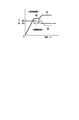
- the figure which shows the mode selection condition of 1st and 2nd Embodiment The flowchart which shows the control of 1st Embodiment.
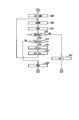
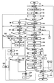
- the flowchart following FIG. 4 and FIG. The flowchart which shows the control of 2nd Embodiment.
- two indoor units B1 and B2 are connected to the outdoor unit A in parallel with each other via a liquid side pipe C1 and a gas side pipe C2.
- a signal line E for data transmission and control is connected between the outdoor unit A and the indoor units B1 and B2.
- a multi-type refrigeration cycle device that performs air conditioning is configured.
- the outdoor unit A functions as a master unit for overall control
- the indoor units B1 and B2 function as slave units that operate according to instructions from the master unit.
- the outdoor unit A includes a compressor 1, a four-way valve 2, an outdoor heat exchanger 3, an expansion valve (decompressor) 4, an accumulator 5, an outdoor fan 6, an outdoor temperature sensor 7, an outdoor controller 8, and a motor drive according to the present embodiment.
- the device 9 is provided. During the cooling operation, as shown by the solid line arrow, the gas refrigerant flowing from the indoor units B1 and B2 to the gas side pipe C2 is sucked into the compressor 1 through the four-way valve 2 and the accumulator 5, compressed by the compressor 1 and discharged.
- the gas refrigerant to be produced flows through the four-way valve 2 to the outdoor heat exchanger 3 (condenser), and the refrigerant that exchanges heat with the outside air in the outdoor heat exchanger 3 and condenses passes through the expansion valve 4 and the liquid side pipe C1. Flows to the indoor units B1 and B2. During the heating operation, the liquid refrigerant flowing from the indoor units B1 and B2 to the liquid side pipe C1 flows through the expansion valve 4 to the outdoor heat exchanger 3 (evaporator), and the outdoor heat exchanger 3 exchanges heat with the outside air.
- the vaporizing refrigerant is sucked into the compressor 1 through the four-way valve 2 and the accumulator 5, and the gas refrigerant compressed and discharged by the compressor 1 passes through the four-way valve 2 and the gas side pipe C2 to the indoor units B1 and B2. It flows.
- the indoor units B1 and B2 include a flow rate adjusting valve 11, an indoor heat exchanger 12, an indoor fan 13, an indoor temperature sensor 14, and an indoor controller 15, respectively.
- the liquid refrigerant flowing from the outdoor unit A to the liquid side pipe C1 flows through the flow rate adjusting valve 11 to the indoor heat exchanger (evaporator) 12, and the indoor heat exchanger 12
- the refrigerant that exchanges heat with the indoor air and vaporizes returns to the outdoor unit A through the gas side pipe C2.
- the gas refrigerant flowing from the outdoor unit A to the gas side pipe C2 flows to the indoor heat exchanger (condenser) 12, and the refrigerant that condenses by exchanging heat with the indoor air in the indoor heat exchanger 12 is the liquid side pipe.
- the flow rate adjusting valve 11 is a pulse motor valve (PMV) whose opening degree continuously changes from fully closed to fully open according to the number of supplied drive voltage pulses.
- the indoor fan 13 sucks indoor air and sends it to the indoor heat exchanger 12.
- the indoor temperature sensor 14 is arranged in the flow path of the indoor air sucked by the indoor fan 13, and detects the temperature Ta of the indoor air.
- the indoor controller 15 detects the difference ⁇ Ta between the detection temperature Ta of the indoor temperature sensor 14 and the preset indoor set temperature Ts as an air conditioning load, and controls the opening degree of the flow rate adjusting valve 11 according to the air conditioning load ⁇ Ta. At the same time, the air conditioning load ⁇ Ta is notified to the outdoor controller 8 by the signal line E.
- the outdoor controller 8 controls the rotation speed of the compressor 1 and the outdoor fan 6 so that the outdoor unit A can exert the ability corresponding to the total load of the air conditioning load ⁇ Ta notified from the indoor units B1 and B2.
- the compressor 1 is a closed type compressor in which the motor 1M shown in FIG. 2 is housed in a closed case together with a compression unit as a drive motor.
- the motor 1M is a permanent magnet synchronous motor (Open-Windings Motor) having a plurality of phase windings Lu, Lv, and Lw that are not connected to each other.
- the phase windings Lu, Lv, and Lw are configured by winding a small-diameter copper wire at a high density so as to improve efficiency in a low rotation speed range (also referred to as a low / medium rotation speed range).
- the motor controller 9b described later is a star that independently switches only the inverter INV1 described later by star-connecting the phase windings Lu, Lv, and Lw (also referred to as star-shaped connection) in the low rotation speed range except at the time of starting.
- connection mode is set, and in the high rotation speed range, the phase windings Lu, Lv, and Lw are set to the unconnected state (open state), and the inverter INV1 and the inverter INV2 described later are linked (also referred to as cooperation) to switch with each other.
- Set the winding mode With this setting, it is possible to perform high-efficiency operation in a wide rotation speed range from the low rotation speed range to the high rotation speed range while enabling high-efficiency operation in the low rotation speed range.
- the motor drive device 9 of the outdoor unit A includes the drive circuit 9a and the motor controller 9b shown in FIG.
- the drive circuit 9a includes a DC power supply unit 40 that full-wave rectifies and smoothes and outputs the AC voltage of the three-phase AC power supply 50, the output end of the DC power supply unit 40, and the phase winding Lu, Lv of the open winding motor 1M.
- Inverter (first inverter; also called master inverter) INV1 that controls the energization between one end of Lw, and the output end of the DC power supply unit 40 and the other end of the phase winding Lu, Lv, Lw of the open winding motor 1M.
- inverter (second inverter; also referred to as a slave inverter) INV2 that controls the energization between the two.
- a common power supply system is adopted in which the DC power supply unit 40 is a common DC power supply for the inverters INV1 and INV2.
- the inverter INV1 is a first series circuit in which the upstream switch element Tu1 and the downstream switch element Tx1 are connected in series and their interconnection points are connected to one end of the phase winding Lu, the upstream switch element Tv1 and the downstream switch element Ty1.
- the third series circuit connected to each other is connected in parallel to each other, and energization from the positive output end of the DC power supply unit 40 to one end of the phase windings Lu, Lv, Lw and DC from one end of the phase windings Lu, Lv, Lw.
- the energization of the negative output end of the power supply unit 40 is controlled by switching the upstream switch elements Tu1 to Tw1 and the downstream switch elements Tx1 to Tz1.
- a diode (also referred to as a freewheel diode) D is connected in antiparallel to each of the upstream switch elements Tu1 to Tw1 and the downstream switch elements Tx1 to Tz1.
- an IGBT is used as the upstream switch elements Tu1 to Tw1 and the downstream switch elements Tx1 to Tz1.
- the inverter INV2 is a fourth series circuit in which the upstream switch element Tu2 and the downstream switch element Tx2 are connected in series and their interconnection points are connected to the other end of the phase winding Lu, the upstream switch element Tv2 and the downstream switch element.
- the sixth series circuit connected to the other end of the circuit is connected in parallel with each other, and the other side of the phase winding Lu, Lv, Lw is energized from the positive output end of the DC power supply unit 40 and the phase winding Lu, Lv, Lw.
- the energization from the other end of the DC power supply unit 40 to the negative output end of the DC power supply unit 40 is controlled by switching the upstream switch elements Tu2 to Tw2 and the downstream switch elements Tx2 to Tz2.
- Diodes D are connected in antiparallel to the upstream switch elements Tu2 to Tw2 and the downstream switch elements Tx2 to Tz2, respectively.
- an IGBT is used as the upstream switch elements Tu2 to Tw2 and the downstream switch elements Tx2 to Tz2.
- the inverter INV1 actually has a single main circuit formed by connecting the first to third series circuits in parallel to each other and peripheral circuits such as a drive circuit for driving each switch element of the main circuit.
- the module stored in the package is the so-called IPM (Intelligent Power Module).
- the inverter INV2 is also an IPM having a similar configuration.
- a normally open contact (referred to as a relay contact) 51a of a relay 51 is connected as a first switch between the other end of the phase winding Lu of the motor 1M and the other end of the phase winding Lv, and the phase winding of the motor 1M.
- a normally open contact (referred to as a relay contact) 52a of the relay 52 is connected as a second switch between the other end of the wire Lv and the other end of the phase winding Lw.
- the relays 51 and 52 are urged and de-energized by the motor controller 9b in a state of being synchronized with each other.
- the relay contacts 51a and 52a are closed, the other ends of the phase windings Lu, Lv and Lw are interconnected, and the phase windings Lu, Lv and Lw are in a star connection state. ..
- the relay contacts 51a and 52a are opened, and the phase windings Lu, Lv and Lw are in a disconnected state, that is, an electrically separated open winding state.
- the motor controller 9b controls the drive circuit 9a in response to a command from the outdoor controller 8, and includes a main control unit 60, a current detection unit 61, a relay drive unit 62, a display unit 63, relays 51, 52, and the like.
- the current detection unit 61 detects the currents (referred to as motor currents) Iu, Iv, Iw flowing in the phase windings Lu, Lv, Lw of the motor 1M based on the output signals of the current sensors 53, 53v, 53w.
- the relay drive unit 62 urges (energizes on) and deenergizes (energizes off) the relays 51 and 52 in response to a command from the main control unit 60.
- the main control unit 60 is composed of a microcomputer and its peripheral circuits, and controls switching of relay contacts 51a and 52a and switching of inverters INV1 and INV2 according to a command from the outdoor controller 8 and a detection result of the current detection unit 62. do.
- the main control unit 60 has an open winding mode in which the other ends of the phase windings Lu, Lv, and Lw are disconnected by opening the relay contacts 51a and 52a, and the inverters INV1 and INV2 are switched in conjunction with each other.
- the star connection mode in which the other ends of the phase windings Lu, Lv, and Lw are interconnected by closing the relay contacts 51a and 52a and the inverter INV1 is switched independently is selectively set.
- the main control unit 60 includes a rotation speed detection unit 60a, a first control unit 60b, a second control unit 60c, and a third control unit 60d as main configurations related to the setting of these modes.
- the rotation speed detection unit 60a detects (also referred to as estimation) the rotation speed (also referred to as speed) N of the motor 1M based on the motor currents Iu, Iv, and Iw detected by the current detection unit 61.
- the first control unit 60b sets the open winding mode when the motor 1M is started, and the detected rotation speed N of the rotation speed detecting unit 60a rises to a predetermined value N3 in the high rotation speed range under the mode selection condition of FIG. It controls the switching of the open winding mode (linkage switching of inverters INV1 and INV2). Then, after the detected rotation speed N of the rotation speed detecting unit 60a rises to the predetermined value N3 (for example, 50 rps), the first control unit 60b has a target rotation speed (also a target speed) corresponding to the allocation capacity from the outdoor controller 8.
- the open winding mode is set and the rotation speed detection unit 60a is opened so that the detection rotation speed N becomes the target rotation speed Nt.
- the star connection mode is set and the detection rotation speed N of the rotation speed detection unit 60a is the target rotation speed.
- the switching of the open winding mode (single switching of the inverter INV1) is controlled so as to be several Nt.
- the mode selection condition specifies the star connection mode when the target rotation speed Nt is in the low rotation speed range less than the second threshold value N2 (for example, 40 rps) when the target rotation speed Nt changes in the ascending direction, and the target rotation speed Nt Specifies the open winding mode when is in the high rotation speed range of the second threshold value N2 or more. Further, the mode selection condition is an open winding when the target rotation speed Nt is in a high rotation speed range exceeding the first threshold value N1 (for example, 35 rps) slightly lower than the second threshold value N2 when the target rotation speed Nt changes in the downward direction.
- the line mode is specified, and the star connection mode is specified when the target rotation speed Nt is in the low rotation speed range of the first threshold value N1 or less.
- the second control unit 60c when an abnormality occurs in which the detection rotation speed N of the rotation speed detection unit 60a suddenly drops, or any of the motor currents Iu, Iv, and Iw detected by the current detection unit 61 is excessive or too small.
- the switching of the inverters INV1 and INV2 is terminated and the motor 1M is stopped. Stopping the motor 1M when such an abnormality occurs is called an abnormal stop of the motor 1M.
- the causes of the abnormality are short-circuit failure or open failure of any of the switch elements in the inverters INV1 and INV2, step-out in which the switching of the inverters INV1 and INV2 and the actual rotation of the motor 1M are not synchronized, and the power supply voltage drops temporarily. There is a sag etc.
- the third control unit 60d sets the star connection mode instead of the open winding mode and restarts the motor 1M. Specifically, when the motor 1M stops abnormally when the open winding mode is set, the third control unit 60d first restarts the motor 1M with the open winding mode set, and also in this restart. Regardless, if the abnormal stop of the motor 1M reoccurs, the star connection mode is set instead of the open winding mode, and the motor 1M is restarted. Then, the third control unit 60d stops the driving of the motor 1M when the abnormal stop of the motor 1M continues even though the star connection mode is set and the motor 1M is restarted.
- the second control unit 60c has a function of abnormally stopping the motor 1M when the abnormal temperature of the compressor 1 or the motor 1M rises. Along with this, when the motor 1M is abnormally stopped due to an abnormal temperature rise, the third control unit 60d is at the time when the abnormal temperature rise is resolved regardless of whether the open winding mode or the star connection mode is set. Restart motor 1M.
- the motor controller 9b sets the abnormality determination flag f of the motor controller 9b to "0" and the retry counts R1, R2 of the motor controller 9b. Clear each R3 to "0" (S2). Then, the motor controller 9b maintains the open state of the relay contacts 51a and 52a (that is, the non-connected state of the phase windings Lu, Lv and Lw) due to the deenergization (energization off) of the relays 51 and 52, and the inverters INV1 and INV2. Set the open winding mode for linked switching (S3). Subsequently, the motor controller 9b controls the switching of the open winding mode so that the detected rotation speed N of the rotation speed detecting unit 60a rises to a predetermined value N3 in the high rotation speed region (S4).
- a part of the current path formed in the open winding mode is shown by a broken line in FIG.
- the upstream switch element Tu1 of the inverter INV1 is turned on and the downstream switch element Tx2 of the inverter INV2 is repeatedly turned on and off, and the upstream switch elements Tv2 and Tw2 of the inverter INV2 are both turned on and the downstream side of the inverter INV1.
- the switch elements Ty1 and Tz1 repeatedly turn on and off in synchronization with each other.
- a current flows from the positive output end of the DC power supply unit 40 to the phase winding Lu through the upstream switch element Tu1, and the current passing through the phase winding Lu flows to the downstream switch element.
- the upstream switch element Tv1 of the inverter INV1 is turned on, the downstream switch element Ty2 of the inverter INV2 is repeatedly turned on and off, and the upstream switch elements Tu2 and Tw2 of the inverter INV2 are both turned on and downstream of the inverter INV1.
- the side switch elements Tx1 and Tz1 repeat on and off in synchronization with each other.
- a current flows from the positive output end of the DC power supply unit 40 to the phase winding Lv through the upstream switch element Tv1, and the current passing through the phase winding Lv passes through the downstream switch element Ty2 to the DC power supply unit.
- a current flows from the positive output end of the DC power supply unit 40 through the upstream switch elements Tu2 and Tw2 to the phase windings Lu and Lw, and passes through the phase windings Lu and Lw.
- the upstream switch element Tw1 of the inverter INV1 is turned on and the downstream switch element Tz2 of the inverter INV2 is repeatedly turned on and off, and the upstream switch elements Tu2 and Tv2 of the inverter INV2 are both turned on and downstream of the inverter INV1.
- the side switch elements Tx1 and Ty1 repeat on and off in synchronization with each other. As a result, a current flows from the positive output end of the DC power supply unit 40 to the phase winding Lw through the upstream switch element Tw1, and the current passing through the phase winding Lw passes through the downstream switch element Tz2 to the DC power supply unit.
- a current flows from the positive output end of the DC power supply unit 40 through the upstream switch elements Tu2 and Tv2 to the phase windings Lu and Lv, and passes through the phase windings Lu and Lv.
- a current flows through the downstream switch elements Tx1 and Ty1 to the negative output end of the DC power supply unit 40.
- the star connection mode that urges the relays 51 and 52 to close the relay contacts 51a and 52a is set in the low rotation speed range.
- the number of operations of the relay contacts 51a and 52a can be reduced as compared with the case of shifting to the open winding mode in the subsequent high rotation speed range. That is, it is possible to exhibit sufficient air conditioning capacity capable of dealing with an unstable high air conditioning load while suppressing the number of operations of the relay contacts 51a and 52a to be small.
- the motor controller 9b receives the motor 1M until the detected rotation speed N of the rotation speed detection unit 60a reaches a predetermined value N3 in the high rotation speed range (NO in S5). Monitor abnormal stoppage (S6). If there is no abnormal stop (NO in S7), the motor controller 9b returns to S4 and is set to the open winding mode so that the detected rotation speed N of the rotation speed detection unit 60a rises to a predetermined value N3 in the high rotation speed range. Continue switching (S4).
- the motor controller 9b determines that the start of the motor 1M is completed for a predetermined time.
- the switching of the open winding mode is controlled so that the detected rotation speed N of the rotation speed detecting unit 60a holds a predetermined value N3 over t (S13).
- the predetermined time t is, for example, about 30 seconds from the start of the compressor 1 until the operation of the refrigeration cycle stabilizes.
- the predetermined time t is too long, the difference between the target rotation speed Nt and the actual rotation speed N after the predetermined time t has elapsed widens, and it takes too much time for the rotation speed N to reach the target rotation speed Nt. It ends up. Generally, about 10 seconds to 1 minute is selected as the predetermined time t so that such a problem does not occur.
- the motor controller 9b After the lapse of the predetermined time t, the motor controller 9b sets the target rotation speed Nt corresponding to the allocation capacity from the outdoor controller 8 (S14). Then, since the current abnormality determination flag f is “0” (YES in S15), the motor controller 9b determines whether the target rotation speed Nt set above is in the high rotation speed range or the low rotation speed range (YES in S15). S16).
- the motor controller 9b When the target rotation speed Nt is in the high rotation speed range (YES in S16), the motor controller 9b continues to set the open winding mode (S17), and the detection rotation speed N of the rotation speed detection unit 60a is the target rotation speed. The switching of the open winding mode is controlled so as to be Nt (S18). Subsequently, the motor controller 9b monitors the abnormal stop of the motor 1M (S19). When there is no abnormal stop (NO in S20), the motor controller 9b clears the retry count R2 to "0" (S26), and proceeds to the determination of the operation stop command in S27. If there is no stop command (NO in S27), the motor controller 9b returns to S14 and resets the target rotation speed Nt (S14).
- the motor controller 9b shifts to S29 in FIG. 5, closes the switches 51a and 52a, and is in the star connection mode. Is set, and switching in the star connection mode is controlled so that the detected rotation speed N of the rotation speed detecting unit 60a becomes the target rotation speed Nt (S30). Subsequently, the motor controller 9b monitors the abnormal stop of the motor 1M (S31). If there is no abnormal stop (NO in S32), the motor controller 9b clears the retry count R3 to "0" (S37), and moves on to the determination of the operation stop command in S27. When there is a stop command (YES in S27), the motor controller 9b de-energizes (energizes off) the relays 51 and 52 and ends the switching of the inverters INV1 and INV2, thereby stopping the motor drive (S28).
- the motor controller 9b returns to S4 and continues switching in the open winding mode so that the detected rotation speed N of the rotation speed detection unit 60a rises to a predetermined value N3 in the high rotation speed range (S4).
- the motor controller 9b again monitors the abnormal stop of the motor 1M until the detected rotation speed N of the rotation speed detection unit 60a reaches a predetermined value N3 in the high rotation speed range (NO in S5). (S6). If there is no abnormal stop (NO in S7), the motor controller 9b returns to S4 and its open winding mode so that the detected rotation speed N of the rotation speed detection unit 60a rises to a predetermined value N3 in the high rotation speed range. Continue switching (S4).
- the motor controller 9b determines whether the retry count R1 is equal to or less than the set value R1s (S8). At this point, the retry count R1 is "1" which is equal to or less than the set value R1s (YES in S8), so the motor controller 9b of the inverters INV1 and INV2 to restart the motor 1M with the current open winding mode setting. While continuing the linked switching (S9), the retry count R1 is increased by "1" (S10). Subsequently, the motor controller 9b returns to S4 and continues switching in the open winding mode so that the detected rotation speed N of the rotation speed detection unit 60a rises to a predetermined value N3 in the high rotation speed range (S4).
- the motor 1M of the motor controller 9b is abnormal.
- the user is notified by the character display or the image display of the display unit 63 that the state is stopped (S11), and "1" is set in the abnormality determination flag f (S12).
- the motor controller 9b shifts to the above S14, sets the target rotation speed Nt (S14), and confirms the abnormality determination flag f (S15).
- the motor controller 9b shifts to the above S29 in FIG. 5 to set the star connection mode (S29), and the rotation speed detection unit 60a detects and rotates.
- the switching of the star connection mode is controlled so that the number N becomes the target rotation speed Nt (S30). That is, the motor controller 9b starts restarting in the star connection mode instead of the restarting in the open winding mode so far.
- the cause of the abnormal stop is an open failure in which any of the switch elements Tu2 to Tz2 in the inverter INV2 remains off and does not turn on, it becomes impossible to start the motor 1M in the open winding mode in which the inverters INV1 and INV2 are linked and switched. However, it is possible to start the motor 1M in the star connection mode in which the inverter INV1 is switched independently. In consideration of this point, the motor controller 9b is restarted in the star connection mode instead of the restart in the open winding mode.
- the motor controller 9b monitors the abnormal stop of the motor 1M (S31). If there is no abnormal stop (NO in S32), the motor controller 9b clears the retry count R3 to "0" (S37), and moves on to the determination of the operation stop command in S27. If there is no stop command (NO in S27), the motor controller 9b returns to S14 and sets the target rotation speed Nt (S14). Then, since the abnormality determination flag f is "1" (NO in S15), the motor controller 9b continues to set the star connection mode in S29. In the operation in the star connection mode, the voltage that can be applied to the phase windings Lu, Lv, and Lw of the motor 1M is lower than that in the open winding mode. Therefore, in the operation in the star connection mode, when the target rotation speed Nt is high, it is necessary to limit the actual rotation speed N up to the rotation speed at which the motor 1M can be efficiently rotated.
- the motor controller 9b returns to S18, and again controls switching in the open winding mode so that the detected rotation speed N of the rotation speed detection unit 60a becomes the target rotation speed Nt (S18), while controlling the switching of the motor 1M.
- Monitor abnormal stop S19.
- the motor controller 9b clears the retry count R2 to "0" (S26), and proceeds to the determination of the operation stop command in S27.
- the motor 1M of the motor controller 9b is abnormal.
- the user is notified by the character display or the image display of the display unit 63 that the state is stopped (S24), and “1” is set in the abnormality determination flag f (S25).
- the motor controller 9b shifts to the above S14, sets the target rotation speed Nt (S14), and confirms the abnormality determination flag f (S15).
- the motor controller 9b shifts to the above S29 to set the star connection mode (S29), and the rotation speed detection unit 60a detects the rotation speed N.
- the independent switching of the star connection mode is controlled so that the target rotation speed is Nt (S30). That is, the motor controller 9b drives the motor in the star connection mode instead of the motor drive in the open winding mode.
- the cause of the abnormal stop is an open failure in which one of the switch elements Tu2 to Tz2 in the inverter INV2 remains off and does not turn on
- the motor drive in the open winding mode in which the two inverters INV1 and INV2 are linked and switched becomes impossible. It is possible to drive the motor in the star connection mode in which the inverter INV1 is switched independently.
- the motor controller 9b monitors the abnormal stop of the motor 1M (S31). If there is no abnormal stop (NO in S32), the motor controller 9b clears the retry count R3 to "0" (S37), and moves on to the determination of the operation stop command in S27. If there is no stop command (NO in S27), the motor controller 9b returns to S14, sets the target rotation speed Nt (S14), and confirms the abnormality determination flag f (S15). At this point, since the abnormality determination flag f is “1” (NO in S15), the motor controller 9b continues to set the star connection mode in S29.
- the motor controller 9b returns to the above S30, and (S30) abnormally stops the motor 1M while controlling the independent switching of the star connection mode so that the detected rotation speed N of the rotation speed detection unit 60a becomes the target rotation speed Nt. Monitor again (S31). If there is no abnormal stop (NO in S32), the motor controller 9b clears the retry count R3 to "0" (S37), and moves on to the determination of the operation stop command in S27. If there is no stop command (NO in S27), the motor controller 9b returns to S14 and sets the target rotation speed Nt (S14).
- the motor 1M of the motor controller 9b is abnormal.
- the user is notified by displaying characters or images on the display unit 63 that the vehicle is in a stopped state (S36).
- the motor controller 9b de-energizes the relays 51 and 52 and ends the independent switching of the inverter INV1 to stop the motor drive (S28).
- the motor controller 9b immediately stops the motor drive.
- the star connection mode is set instead of the open winding mode, and the motor 1M is restarted by the independent switching of the star connection mode. Since it is started, if the cause of the abnormal stop is an open failure of any of the switch elements Tu2 to Tz2 in the inverter INV2, the motor 1M can be driven in the star connection mode. As a result, the operation of the refrigeration cycle device can be continued as an emergency.
- the third control unit 60d of the motor controller 9b includes a failure detection process for the inverters INV1 and INV2 when the motor 1M stops abnormally.
- the third control unit 60d detects the presence or absence of a failure in the inverters INV1 and INV2 when the motor 1M stops abnormally when the open winding mode is set. Then, as a result of this detection, if there is no failure in the inverter INV1, the third control unit 60d sets the star connection mode and restarts the motor 1M using only the inverter INV1. Further, the third control unit 60d drives the motor 1M based on the judgment that it is difficult to drive the motor when the inverter INV1 has a failure or when the motor 1M continues to stop abnormally despite the restart. Stop.
- the motor controller 9b determines whether the retry count R1 is a set value (for example, “2”) R1s or less. (S8). At this point, the retry count R1 is “0” which is equal to or less than the set value R1s (YES in S8), so the motor controller 9b switches the inverters INV1 and INV2 in order to restart the motor 1M with the open winding mode set. (S9) and increase the retry count R1 by "1" (S10). Subsequently, the motor controller 9b returns to S4 and continues switching in the open winding mode so that the detected rotation speed N of the rotation speed detection unit 60a rises to a predetermined value N3 in the high rotation speed range (S4).
- the retry count R1 is a set value (for example, “2”) R1s or less.
- the motor controller 9b notifies the user that the motor 1M is in an abnormally stopped state by displaying characters or an image on the display unit 63 (S11), and at the same time, the abnormality. “1” is set in the determination flag f (S12). Then, the motor controller 9b shifts to the above S14, sets the target rotation speed Nt (S14), and confirms the abnormality determination flag f (S15).
- the motor controller 9b shifts to the above S29 to set the star connection mode (S29), and the rotation speed detection unit 60a detects the rotation speed N.
- the switching of the star connection mode is controlled so that the target rotation speed is Nt (S30). That is, the motor controller 9b starts restarting in the star connection mode instead of starting in the open winding mode so far.
- the motor controller 9b In the failure detection of S41, if there is no open failure in the switch elements Tu1 to Tz1 of the inverter INV1 and there is an open failure in any of the switch elements Tu2 to Tz2 of the inverter INV2 (NO in S42, YES in S43), the motor controller 9b notifies the user that the motor 1M is in an abnormally stopped state and that the inverter INV2 is out of order by displaying characters or images on the display unit 63 (S11), and sets the abnormality determination flag f to "1". Set (S12). Then, the motor controller 9b shifts to the above S14, sets the target rotation speed Nt (S14), and confirms the abnormality determination flag f (S15).
- the motor controller 9b shifts to the above S29 to set the star connection mode (S29), and the rotation speed detection unit 60a detects the rotation speed N.
- the switching of the star connection mode is controlled so that the target rotation speed is Nt (S30). That is, the motor controller 9b starts restarting in the star connection mode instead of starting in the open winding mode so far.
- the cause of the abnormal stop is an open failure of any of the switch elements Tu2 to Tz2 in the inverter INV2, it is impossible to start the motor 1M in the open winding mode in which the inverters INV1 and INV2 are linked and switched, but at least the inverter INV1 If there is no failure, the motor 1M can be started in the star connection mode in which the inverter INV1 is switched independently.
- the motor controller 9b determines whether the retry count R2 is equal to or less than the set value R2s (S21). When the retry count R2 is equal to or less than the set value R2s (YES in S21), the motor controller 9b continues the linked switching of the inverters INV1 and INV2 in order to restart the motor 1M while keeping the open winding mode setting (S22). , The retry count R2 is increased by "1" (S23). Subsequently, the motor controller 9b returns to S18 and continues switching in the open winding mode so that the detected rotation speed N of the rotation speed detection unit 60a becomes a predetermined value N3 in the high rotation speed range (S18).
- the motor controller 9b notifies the user that the motor 1M is in an abnormally stopped state by displaying characters or an image on the display unit 63 (S24), and sets the abnormality determination flag f to ". 1 ”is set (S25). Then, the motor controller 9b shifts to the above S14, sets the target rotation speed Nt (S14), and confirms the abnormality determination flag f (S15).
- the motor controller 9b shifts to the above S29 to set the star connection mode (S29), and the rotation speed detection unit 60a detects the rotation speed N.
- the switching of the star connection mode is controlled so that the target rotation speed is Nt (S30). Instead of starting in the open winding mode so far, restarting in the star connection mode will start.
- the motor controller 9b In the failure detection of S45, if there is no open failure in the switch elements Tu1 to Tz1 of the inverter INV1 and there is an open failure in any of the switch elements Tu2 to Tz2 of the inverter INV2 (NO in S46, YES in S47), the motor The controller 9b notifies the user that the motor 1M is in an abnormally stopped state and that the inverter INV2 is out of order by displaying characters or images on the display unit 63 (S24), and sets the abnormality determination flag f to “1”. Is set (S25). Then, the motor controller 9b shifts to the above S14, sets the target rotation speed Nt (S14), and confirms the abnormality determination flag f (S15).
- the motor controller 9b shifts to the above S29 to set the star connection mode (S29), and the rotation speed detection unit 60a detects the rotation speed N.
- the switching of the star connection mode is controlled so that the target rotation speed is Nt (S30). That is, the motor controller 9b drives the motor in the star connection mode instead of the conventional motor drive in the open winding mode.
- the cause of the abnormal stop is an open failure in which any of the switch elements Tu2 to Tz2 in the inverter INV2 remains off and does not turn on, it becomes impossible to drive the motor 1M in the open winding mode in which the inverters INV1 and INV2 are linked and switched.
- the inverter INV1 it is possible to drive the motor 1M in the star connection mode in which the inverter INV1 is switched independently.
- the motor controller 9b notifies the user that the inverter INV1 is out of order by displaying characters or images on the display unit 63 (S44), and moves to S28 to stop the motor drive (S28).
- FIG. 7 shows the failure detection routines of S41 and S45 executed by the motor controller 9b when the motor 1M stops abnormally.
- the motor controller 9b first, only the upstream switch element Tu1 and the downstream switch element Tx2 are turned on, whereby the upstream switch element Tu1 from the positive output end of the DC power supply unit 40, the other end of the phase winding Lu, and the downstream.
- a first energizing path through which current flows to the negative output end of the side switch element Tx2 and the DC power supply unit 40 is formed (S51).
- the motor controller 9b only the upstream switch element Tv1 and the downstream switch element Ty2 are turned on, whereby the upstream switch element Tv1 and the phase winding Lv from one end to the other end of the DC power supply unit 40 are turned on.
- the downstream switch element Ty2 forms a second current-carrying path through which a current flows to the negative output end of the DC power supply unit 40 (S52).
- the motor controller 9b turns on only the upstream switch element Tw1 and the downstream switch element Tz2, whereby from the positive output end of the DC power supply unit 40 to the upstream switch element Tw1 and from one end to the other end of the phase winding Tw.
- the downstream switch element Tz2 forms a third current-carrying path through which current flows to the negative output end of the DC power supply unit 40 (S53).
- the motor controller 9b only the upstream switch element Tu2 and the downstream switch element Tx1 are turned on, whereby from the positive output end of the DC power supply unit 40 to the upstream switch element Tu2 and one end from the other end of the phase winding Lu.
- the downstream switch element Tx1 forms a fourth current-carrying path through which a current flows to the negative output end of the DC power supply unit 40 (S54).
- the upstream switch element Tv2 and the downstream switch element Ty1 are turned on, whereby from the positive output end of the DC power supply unit 40 to the upstream switch element Tv2 and one end from the other end of the phase winding Lv.
- the downstream switch element Ty1 forms a fifth current-carrying path through which a current flows to the negative output end of the DC power supply unit 40 (S55).
- the upstream switch element Tw2 and the downstream switch element Tz1 are turned on, whereby from the positive output end of the DC power supply unit 40 to the upstream switch element Tw2 and one end from the other end of the phase winding Lw.
- a sixth current-carrying path through which a current flows to the downstream switch element Tz1 and the negative output end of the DC power supply unit 40 is formed (S56).
- the motor controller 9b determines whether or not there is energization at the time of forming the first energization path and the sixth energization path based on the motor currents Iu, Iv, and Iw detected by the current detection unit 61 (S57, S58, S59). In this determination, when there is energization in the formation of either the first energization path or the sixth energization path (NO in S57, NO in S58, NO in S59), the motor controller 9b is the switch element of the inverters INV1 and INV2. It is judged that there is no open failure (S60).
- the motor controller 9b is the relay contact 51a of the relay contacts 51a and 52a. Only (S61) is closed, and only the upstream switch element Tu1 and the downstream switch element Ty1 on the inverter INV1 side are turned on (S62), whereby the upstream switch element Tu1 and the phase are turned on from the positive output end of the DC power supply unit 40.
- a seventh current flow path is formed from one end to the other end of the winding Lu, the relay contact 51a, the other end of the phase winding Lv to one end, the downstream switch element Ty1, and the negative output end of the DC power supply unit 40. ..
- the motor controller 9b is the relay contact 52a of the relay contacts 51a and 52a. Only the upstream switch element Tv1 on the inverter INV1 side and the downstream switch element Tz1 are turned on (S64), whereby the upstream switch element Tv1 and the phase are turned on from the positive output end of the DC power supply unit 40.
- An eighth current flow path is formed from one end to the other end of the winding Lv, the relay contact 52a, the other end of the phase winding Lw to one end, the downstream switch element Tz1, and the negative output end of the DC power supply unit 40. ..
- the motor controller 9b closes the relay contacts 51a and 52a together.
- the motor controller 9b determines that there is an open failure only in the inverter INV2 when there is energization in the formation of any of the 7th energization path to the 9th energization path (NO in S67) (S68). When there is no energization when forming either the 7th energization path or the 9th energization path (YES in S67), the motor controller 9b determines that only the inverter INV1 has an open failure (S69).
- the motor controller 9b determines that the upstream switch element Tu1 or the downstream switch element Ty1 of the inverter INV1 has an open failure (S69). ). When there is no energization when forming the eighth energization path (NO in S67), the motor controller 9b determines that the upstream switch element Tv1 or the downstream switch element Tz1 of the inverter INV1 has an open failure (S69).
- the motor controller 9b determines that the upstream switch element Tw1 or the downstream switch element Tx1 of the inverter INV1 has an open failure (S69).
- the motor currents Iu, Iv, Iw are detected by using three current sensors 53u, 53v, 53w, but one of the current sensors, for example, the current sensor 53w, is removed and the motor currents Iu, Iv, A single current sensor (current transformer) for detecting the total value of Iw is provided, and the motor current Iw detected by the removed current sensor 53w is the motor currents Iu and Iv detected by the remaining current sensors 53u and 53v. It may be detected by the calculation using the detection current of the single current sensor.
- the common power supply method in which the inverters INV1 and INV2 are connected to the same DC power supply unit 40 is adopted, but the same can be implemented in the power supply isolation method in which the inverters INV1 and INV2 are connected to different DC power supplies.
- Main control unit 60a ... Rotation speed detection unit, 60b ... 1st control unit, 60c ... 2nd control unit, 60d ... 3rd control unit, 61 ... current detection unit, 62 ... relay drive unit, 63 ... display unit
Landscapes
- Engineering & Computer Science (AREA)
- Power Engineering (AREA)
- Control Of Ac Motors In General (AREA)
Abstract
モータ駆動装置は、開閉器の開放によりモータの各相巻線の他端を非接続状態とし第1および第2インバータを互いに連係してスイッチングするオープン巻線モード、及び上記開閉器の閉成により上記各相巻線の他端を相互接続し上記第1インバータをスイッチングするスター結線モードを、選択的に設定する。そして、モータ駆動装置は、上記オープン巻線モードの設定時に上記モータが異常停止した場合、そのオープン巻線モードに代えて上記スター結線モードを設定し、上記モータを再起動する。
Description
本発明は、互いに非接続状態の複数の相巻線を有する永久磁石同期モータいわゆるオープン巻線モータを駆動するモータ駆動装置及びそのモータ駆動装置を備える冷凍サイクル装置に関する。
空気調和機等の冷凍サイクル装置に搭載される圧縮機の駆動モータとして、複数の相巻線を有する永久磁石同期モータが使用される。また、永久磁石同期モータ(DCブラシレスモータともいう)の一例として、複数の相巻線を互いに非接続状態とした構成のオープン巻線モータ(Open-Windings Motor)が知られている。
このオープン巻線モータ(モータと略称する)を駆動するモータ駆動装置は、モータの各相巻線の一端への通電を制御する第1インバータ、モータの各相巻線の他端への通電を制御する第2インバータ、各相巻線の他端の相互間に接続される開閉器を備え、この開閉器の閉成により各相巻線をスター結線(星形結線ともいう)して第1インバータを単独でスイッチングするスター結線モード、及び開閉器の開放により各相巻線を非接続状態として第1および第2インバータを互いに連係してスイッチングするオープン巻線モードを、選択的に設定する。
オープン巻線モードでは、スター結線モード時の約2倍の電圧を各相巻線に印加することができる。この点を考慮し、モータ駆動装置は、モータの回転数(速度)が閾値未満の低回転数域(低・中回転数域ともいう)ではスター結線モードを設定し、モータの回転数が負荷に応じた目標回転数となるよう第1インバータのスイッチングを制御する。モータの回転数が閾値以上の高回転数域ではオープン巻線モードを設定し、モータの回転数が負荷に応じた目標回転数となるよう第1および第2インバータのスイッチングを制御する。このようにスター結線モードとオープン巻線モードを切換えることで、低回転数域から高回転数域まで幅広い回転数範囲で高効率の運転を行うことができる。
第1および第2インバータのスイッチ素子に故障が生じると、モータ駆動が困難となる。ビル用の空気調和機や熱源装置等の大型の業務用設備として用いられる冷凍サイクル装置では、機器が故障で停止すると使用者に迷惑がかかったり、製造工程では生産に遅延を招いたりすることから、極力運転を継続できるようにすることが望まれる。
本発明の実施形態の目的は、第1および第2インバータのスイッチ素子に故障が生じた場合でも、故障の状態によってはモータ駆動を続けることができるモータ駆動装置及び冷凍サイクル装置を提供することである。
請求項1のモータ駆動装置は、開閉器の開放によりモータの各相巻線の他端を非接続状態とし第1および第2インバータを互いに連係してスイッチングするオープン巻線モード、及び上記開閉器の閉成により上記各相巻線の他端を相互接続し上記第1インバータをスイッチングするスター結線モードを、選択的に設定する。そして、上記オープン巻線モードの設定時に上記モータが異常停止した場合、そのオープン巻線モードに代えて上記スター結線モードを設定し、前記モータを再起動する。
請求項9の冷凍サイクル装置は、上記請求項1に記載のモータ駆動装置を備えたものでであって、上記モータにより駆動され、冷媒を吸込んで圧縮し吐出する圧縮機と;この圧縮機、凝縮器、減圧器、蒸発器を接続して上記冷媒を循環させる冷凍サイクルと;を備える。
[1]第1実施形態
第1実施形態の構成について図面を参照しながら説明する。
第1実施形態の構成について図面を参照しながら説明する。
図1に示すように、室外機Aに液側管C1およびガス側管C2を介して、例えば2台の室内機B1,B2が互いに並列状態で接続されている。そして、室外機Aおよび室内機B1,B2の相互間にデータ伝送用および制御用の信号ラインEが接続されている。これら室外機Aおよび室内機B1,B2の接続により、冷暖房を行うマルチタイプの冷凍サイクル装置が構成される。この冷凍サイクル装置では、室外機Aが全体制御用の親機として機能し、室内機B1,B2が親機からの指示に従って動作する子機として機能する。
室外機Aは、圧縮機1、四方弁2、室外熱交換器3、膨張弁(減圧器)4、アキュームレータ5、室外ファン6、室外温度センサ7、室外コントローラ8、および本実施形態のモータ駆動装置9を備える。冷房運転時、実線矢印で示すように、室内機B1,B2からガス側管C2に流れるガス冷媒が四方弁2およびアキュームレータ5を通って圧縮機1に吸込まれ、その圧縮機1で圧縮され吐出されるガス冷媒が四方弁2を通って室外熱交換器3(凝縮器)に流れ、その室外熱交換器3で外気と熱交換して凝縮する冷媒が膨張弁4および液側管C1を通って室内機B1,B2へ流れる。暖房運転時、室内機B1,B2から液側管C1に流れる液冷媒が膨張弁4を通って室外熱交換器3(蒸発器)に流れ、その室外熱交換器3で外気と熱交換して気化する冷媒が四方弁2およびアキュームレータ5を通って圧縮機1に吸込まれ、その圧縮機1で圧縮され吐出されるガス冷媒が四方弁2およびガス側管C2を通って室内機B1,B2へ流れる。
室内機B1,B2は、それぞれ、流量調整弁11、室内熱交換器12、室内ファン13、室内温度センサ14、および室内コントローラ15を含む。冷房運転時、実線矢印で示すように、室外機Aから液側管C1に流れる液冷媒が流量調整弁11を通って室内熱交換器(蒸発器)12に流れ、その室内熱交換器12で室内空気と熱交換して気化する冷媒がガス側管C2を通って室外機Aへ戻る。暖房運転時、室外機Aからガス側管C2に流れるガス冷媒が室内熱交換器(凝縮器)12に流れ、その室内熱交換器12で室内空気と熱交換して凝縮する冷媒が液側管C1を通って室外機Aへ戻る。流量調整弁11は、供給される駆動電圧パルスの数に応じて開度が全閉から全開まで連続的に変化するパルスモータバルブ(PMV)である。室内ファン13は、室内空気を吸込んで室内熱交換器12に送る。室内温度センサ14は、室内ファン13により吸込まれる室内空気の流路に配置され、その室内空気の温度Taを検知する。室内コントローラ15は、室内温度センサ14の検知温度Taと予め設定される室内設定温度Tsとの差ΔTaを空調負荷として検出し、その空調負荷ΔTaに応じて流量調整弁11の開度を制御するとともに、その空調負荷ΔTaを信号ラインEにより室外コントローラ8に通知する。
室外コントローラ8は、室内機B1,B2から通知される空調負荷ΔTaの合計負荷に対応する能力を室外機Aが発揮できるよう圧縮機1や室外ファン6の回転数等を制御する。
圧縮機1は、図2に示すモータ1Mを駆動モータとして圧縮部と共に密閉ケースに収容した密閉型圧縮機である。モータ1Mは、互いに非接続状態の複数の相巻線Lu,Lv,Lwを有する永久磁石同期モータいわゆるオープン巻線モータ(Open-Windings Motor)である。相巻線Lu,Lv,Lwは、低回転数域(低・中回転数域ともいう)で効率が向上するよう、細径の銅線を高い密度で巻回して構成される。ただし、高密度に多く巻かれた相巻線を用いると、モータ1Mの回転数(速度)の上昇に伴って相巻線Lu,Lv,Lwに誘起する電圧が早期に上昇し、その誘起電圧と後述のインバータから相巻線Lu,Lv,Lwに供給される電圧との差が早い段階で小さくなり、それ以上はモータ1Mの回転数を上昇させることができなくなる。そこで、後述のモータコントローラ9bは、起動時を除き、低回転数域では相巻線Lu,Lv,Lwをスター結線(星形結線ともいう)して後述のインバータINV1のみを単独でスイッチングするスター結線モードを設定し、高回転数域では相巻線Lu,Lv,Lwを非接続状態(オープン状態)として後述のインバータINV1および後述のインバータINV2を互いに連係(協調ともいう)してスイッチングするオープン巻線モードを設定する。この設定により、低回転数域で高効率の運転を可能としながら、その低回転数域から高回転数域まで幅広い回転数範囲で高効率の運転を行うことが可能である。
室外機Aのモータ駆動装置9は、図2に示す駆動回路9aおよびモータコントローラ9bを含む。駆動回路9aは、三相交流電源50の交流電圧を全波整流して平滑し出力する直流電源部40、この直流電源部40の出力端とオープン巻線モータ1Mの相巻線Lu,Lv,Lwの一端との間の通電を制御するインバータ(第1インバータ;マスタインバータともいう)INV1、および直流電源部40の出力端とオープン巻線モータ1Mの相巻線Lu,Lv,Lwの他端との間の通電を制御するインバータ(第2インバータ;スレーブインバータともいう)INV2を含む。直流電源部40をインバータINV1,INV2の共通の直流電源とする電源共通方式を採用している。
インバータINV1は、上流側スイッチ素子Tu1と下流側スイッチ素子Tx1を直列接続しその相互接続点が相巻線Luの一端に接続される第1直列回路、上流側スイッチ素子Tv1と下流側スイッチ素子Ty1を直列接続しその相互接続点が相巻線Lvの一端に接続される第2直列回路、上流側スイッチ素子Tw1と下流側スイッチ素子Tz1を直列接続しその相互接続点が相巻線Lwの一端に接続される第3直列回路を互いに並列接続し、直流電源部40の正側出力端から相巻線Lu,Lv,Lwの一端への通電および相巻線Lu,Lv,Lwの一端から直流電源部40の負側出力端への通電を上流側スイッチ素子Tu1~Tw1および下流側スイッチ素子Tx1~Tz1のスイッチングにより制御する。上流側スイッチ素子Tu1~Tw1および下流側スイッチ素子Tx1~Tz1にはダイオード(フリー・ホイール・ダイオードともいう)Dがそれぞれ逆並列接続されている。上流側スイッチ素子Tu1~Tw1および下流側スイッチ素子Tx1~Tz1として例えばIGBTを用いる。
インバータINV2は、上流側スイッチ素子Tu2と下流側スイッチ素子Tx2を直列接続しその相互接続点が相巻線Luの他端に接続される第4直列回路、上流側スイッチ素子Tv2と下流側スイッチ素子Ty2を直列接続しその相互接続点が相巻線Lvの他端に接続される第5直列回路、上流側スイッチ素子Tw2と下流側スイッチ素子Tz2を直列接続しその相互接続点が相巻線Lwの他端に接続される第6直列回路を互いに並列接続し、直流電源部40の正側出力端から相巻線Lu,Lv,Lwの他端への通電および相巻線Lu,Lv,Lwの他端から直流電源部40の負側出力端への通電を上流側スイッチ素子Tu2~Tw2および下流側スイッチ素子Tx2~Tz2のスイッチングにより制御する。上流側スイッチ素子Tu2~Tw2および下流側スイッチ素子Tx2~Tz2にはダイオードDがそれぞれ逆並列接続されている。上流側スイッチ素子Tu2~Tw2および下流側スイッチ素子Tx2~Tz2として例えばIGBTを用いる。
なお、インバータINV1は、実際には、上記第1~第3直列回路を互いに並列接続してなる主回路、およびこの主回路の各スイッチ素子を駆動する駆動回路などの周辺回路を、単一のパッケージに収納したモジュールいわゆるIPM(Intelligent Power Module)である。インバータINV2も、同様の構成のIPMである。
モータ1Mの相巻線Luの他端と相巻線Lvの他端との間に第1開閉器として例えばリレー51の常開形接点(リレー接点という)51aが接続され、モータ1Mの相巻線Lvの他端と相巻線Lwの他端との間に第2開閉器として例えばリレー52の常開形接点(リレー接点という)52aが接続されている。リレー51,52は、モータコントローラ9bにより、互いに同期した状態で付勢と消勢が制御される。リレー51,52が付勢されるとリレー接点51a,52aが閉成し、相巻線Lu,Lv,Lwの他端が相互接続されて相巻線Lu,Lv,Lwがスター結線状態となる。リレー51,52が消勢されるとリレー接点51a,52aが開放し、相巻線Lu,Lv,Lwが非接続状態つまり電気的に分離したオープン巻線状態となる。
インバータINV1と相巻線Lu,Lv,Lwの一端との間の3つの通電ラインに電流センサ53u,53v,53wが配置され、これら電流センサ53u,53v,53wの出力信号がモータコントローラ9bに送られる。
モータコントローラ9bは、室外コントローラ8からの指令に応じて駆動回路9aを制御するもので、主制御部60、電流検出部61、リレー駆動部62、表示部63、リレー51,52などを含む。電流検出部61は、モータ1Mの相巻線Lu,Lv,Lwに流れる電流(モータ電流という)Iu,Iv,Iwを電流センサ53,53v,53wの出力信号に基づき検出する。リレー駆動部62は、主制御部60からの指令に応じてリレー51,52を付勢(通電オン)および消勢(通電オフ)する。主制御部60は、マイクロコンピュータおよびその周辺回路により構成され、室外コントローラ8からの指令および電流検出部62の検出結果などに応じてリレー接点51a,52aの開閉およびインバータINV1,INV2のスイッチングを制御する。
とくに、主制御部60は、リレー接点51a,52aの開放により相巻線Lu,Lv,Lwの他端を非接続状態としかつインバータINV1,INV2を互いに連係してスイッチングするオープン巻線モード、及びリレー接点51a,52aの閉成により相巻線Lu,Lv,Lwの他端を相互接続しかつインバータINV1を単独でスイッチングするスター結線モードを、選択的に設定する。主制御部60は、これらモードの設定に関わる主要な構成として、回転数検出部60a,第1制御部60b,第2制御部60c,第3制御部60dを含む。
回転数検出部60aは、電流検出部61で検出されるモータ電流Iu,Iv,Iwに基づき、モータ1Mの回転数(速度ともいう)Nを検出(推定ともいう)する。
第1制御部60bは、モータ1Mの起動に際し、オープン巻線モードを設定し、回転数検出部60aの検出回転数Nが図3のモード選択条件における高回転数域の所定値N3まで上昇するよう、そのオープン巻線モードのスイッチング(インバータINV1,INV2の連係スイッチング)を制御する。そして、第1制御部60bは、回転数検出部60aの検出回転数Nが上記所定値N3(例えば50rps)まで上昇した後、室外コントローラ8からの割当て能力に対応する目標回転数(目標速度ともいう)Ntを設定し、この目標回転数Ntが上記高回転数域にある場合はオープン巻線モードを設定して回転数検出部60aの検出回転数Nが目標回転数Ntとなるようそのオープン巻線モードのスイッチングを制御し、上記目標回転数Ntが図3のモード選択条件における低回転数域にある場合はスター結線モードを設定して回転数検出部60aの検出回転数Nが目標回転数Ntとなるようそのオープン巻線モードのスイッチング(インバータINV1の単独スイッチング)を制御する。
モード選択条件は、目標回転数Ntの上昇方向の変化に際し、目標回転数Ntが第2閾値N2(例えば40rps)未満の低回転数域に存する場合にスター結線モードを指定し、目標回転数Ntが第2閾値N2以上の高回転数域に存する場合にオープン巻線モードを指定する。さらに、モード選択条件は、目標回転数Ntの下降方向の変化に際し、目標回転数Ntが第2閾値N2より少し低い第1閾値N1(例えば35rps)超の高回転数域に存する場合にオープン巻線モードを指定し、目標回転数Ntが第1閾値N1以下の低回転数域に存する場合にスター結線モードを指定する。低回転数域と高回転数域の境界に第2閾値N2と第1閾値N1によるヒステリシス幅を設けることにより、スター結線モードとオープン巻線モードの頻繁な切換えを防止している。
第2制御部60cは、回転数検出部60aの検出回転数Nが急低下する異常が生じた場合、あるいは電流検出部61で検出されるモータ電流Iu,Iv,Iwのいずれかが過大または過少に変化する異常が生じた場合等に、インバータINV1,INV2のスイッチングを終了してモータ1Mを停止する。このような異常が生じた場合にモータ1Mを停止することを、モータ1Mの異常停止という。異常の原因として、インバータINV1,INV2における各スイッチ素子のいずれかの短絡故障やオープン故障、インバータINV1,INV2のスイッチングとモータ1Mの実際の回転とが同期しない脱調、電源電圧が一時的に低下するサグ等がある。
第3制御部60dは、オープン巻線モードの設定時にモータ1Mが異常停止した場合、オープン巻線モードに代えてスター結線モードを設定し、モータ1Mを再起動する。なお、第3制御部60dは、具体的には、オープン巻線モードの設定時にモータ1Mが異常停止した場合、先ずオープン巻線モードの設定のままモータ1Mを再起動し、この再起動にもかかわらずモータ1Mの異常停止が再発した場合にオープン巻線モードに代えてスター結線モードを設定し、モータ1Mを再起動する。そして、第3制御部60dは、スター結線モードを設定してモータ1Mを再起動したにもかかわらずモータ1Mの異常停止が続いた場合、モータ1Mの駆動を停止する。
なお、上記第2制御部60cは、圧縮機1やモータ1Mの異常温度上昇に際し、モータ1Mを異常停止する機能を有する。これに伴い、上記第3制御部60dは、異常温度上昇によるモータ1Mの異常停止に際しては、オープン巻線モードおよびスター結線モードのどちらを設定している場合でも、異常温度上昇が解消した時点でモータ1Mを再起動する。
つぎに、モータコントローラ9bが実行する制御を図4およびそれに続く図5のフローチャートを参照しながら説明する。フローチャート中のステップS1,S2…については単にS1,S2…と略称する。
[モータ1Mの起動時]
室外コントローラ8から運転開始指令を受けた場合(S1のYES)、モータコントローラ9bは、当該モータコントローラ9bの異常判定フラグfに“0”をセットするとともに当該モータコントローラ9bのリトライカウントR1,R2,R3をそれぞれ“0”にクリアする(S2)。そして、モータコントローラ9bは、リレー51,52の消勢(通電オフ)によるリレー接点51a,52aの開放状態(つまり相巻線Lu,Lv,Lwの非接続状態)を維持したままインバータINV1,INV2を連係スイッチングするオープン巻線モードを設定する(S3)。続いて、モータコントローラ9bは、回転数検出部60aの検出回転数Nが高回転数域の所定値N3まで上昇するよう、そのオープン巻線モードのスイッチングを制御する(S4)。
室外コントローラ8から運転開始指令を受けた場合(S1のYES)、モータコントローラ9bは、当該モータコントローラ9bの異常判定フラグfに“0”をセットするとともに当該モータコントローラ9bのリトライカウントR1,R2,R3をそれぞれ“0”にクリアする(S2)。そして、モータコントローラ9bは、リレー51,52の消勢(通電オフ)によるリレー接点51a,52aの開放状態(つまり相巻線Lu,Lv,Lwの非接続状態)を維持したままインバータINV1,INV2を連係スイッチングするオープン巻線モードを設定する(S3)。続いて、モータコントローラ9bは、回転数検出部60aの検出回転数Nが高回転数域の所定値N3まで上昇するよう、そのオープン巻線モードのスイッチングを制御する(S4)。
オープン巻線モード時に形成される電流経路の一部を図2に破線で示す。まず、インバータINV1の上流側スイッチ素子Tu1がオンしてインバータINV2の下流側スイッチ素子Tx2がオン,オフを繰返すとともに、インバータINV2の上流側スイッチ素子Tv2,Tw2が共にオンしてインバータINV1の下流側スイッチ素子Ty1,Tz1が互いに同期してオン,オフを繰返す。これにより、破線矢印で示すように、直流電源部40の正側出力端から上流側スイッチ素子Tu1を通って相巻線Luに電流が流れ、その相巻線Luを経た電流が下流側スイッチ素子Tx2を通って直流電源部40の負側出力端に流れるとともに、直流電源部40の正側出力端から上流側スイッチ素子Tv2,Tw2を通って相巻線Lv,Lwに電流が流れ、その相巻線Lv,Lwを経た電流が下流側スイッチ素子Ty1,Tz1を通って直流電源部40の負側出力端に流れる。次に、インバータINV1の上流側スイッチ素子Tv1がオンしてインバータINV2の下流側スイッチ素子Ty2がオン,オフを繰返すとともに、インバータINV2の上流側スイッチ素子Tu2,Tw2が共にオンしてインバータINV1の下流側スイッチ素子Tx1,Tz1が互いに同期してオン,オフを繰返す。これにより、直流電源部40の正側出力端から上流側スイッチ素子Tv1を通って相巻線Lvに電流が流れ、その相巻線Lvを経た電流が下流側スイッチ素子Ty2を通って直流電源部40の負側出力端に流れるとともに、直流電源部40の正側出力端から上流側スイッチ素子Tu2,Tw2を通って相巻線Lu,Lwに電流が流れ、その相巻線Lu,Lwを経た電流が下流側スイッチ素子Tx1,Tz1を通って直流電源部40の負側出力端に流れる。次に、インバータINV1の上流側スイッチ素子Tw1がオンしてインバータINV2の下流側スイッチ素子Tz2がオン,オフを繰返すとともに、インバータINV2の上流側スイッチ素子Tu2,Tv2が共にオンしてインバータINV1の下流側スイッチ素子Tx1,Ty1が互いに同期してオン,オフを繰返す。これにより、直流電源部40の正側出力端から上流側スイッチ素子Tw1を通って相巻線Lwに電流が流れ、その相巻線Lwを経た電流が下流側スイッチ素子Tz2を通って直流電源部40の負側出力端に流れるとともに、直流電源部40の正側出力端から上流側スイッチ素子Tu2,Tv2を通って相巻線Lu,Lvに電流が流れ、その相巻線Lu,Lvを経た電流が下流側スイッチ素子Tx1,Ty1を通って直流電源部40の負側出力端に流れる。これら3パターンの電流経路が順次に切換わることにより、モータ1Mのロータが回転する。
このオープン巻線モードの設定により、スター結線モード時の約√3倍の電圧を相巻線Lu,Lv,Lwに印加することができ、よって運転開始時の高空調負荷に対応する高回転数域へとモータ1Mの回転数Nを効率よく上昇させることが可能となる。
とくに、空気調和機の運転開始時は、空調負荷が高いだけでなく、室内ファン13が動き始めたばかりで新鮮な室内空気が室内温度センサ14にうまく流れないため室内温度検知が不安定な状態にあって、空調負荷を的確に捕らえることが難しい。このような状況では、本実施形態のように、リレー51,52の消勢(通電オフ)によるリレー接点51a,52aの開放状態を維持したままインバータINV1,INV2を連係スイッチングするオープン巻線モードを初めから設定してモータ1Mの回転数Nを高回転数域まで上昇させるほうが、リレー51,52を付勢してリレー接点51a,52aを閉成するスター結線モードを低回転数域で設定しその後の高回転数域でオープン巻線モードに移行する場合よりも、リレー接点51a,52aの作動回数を少なくすることができる。つまり、リレー接点51a,52aの作動回数を少なく抑えながら、不安定な高空調負荷に対処し得る十分な空調能力を発揮することが可能となる。
また、空気調和機の運転開始時は、圧縮機1の起動に伴い、圧縮機1の密閉ケース内に存する潤滑油の一部が冷媒と混合した状態で冷凍サイクル中に流出し、流出した潤滑油が冷凍サイクルを巡って圧縮機1の密閉ケースに徐々に戻るようになる。流出した潤滑油が圧縮機1の密閉ケースに戻るまでの間、圧縮機1において潤滑油が不足気味となる。この潤滑油不足は、圧縮機1の寿命に悪影響を与える。しかしながら、本実施形態では、起動するモータ1Mの回転数Nが高回転数域まで一気に上昇するので、圧縮機1の密閉ケース内の潤滑油が冷凍サイクル中に流出して一旦は減少しても、流出した潤滑油は冷凍サイクルを迅速に巡って圧縮機1の密閉ケースに早期に戻る。流出した潤滑油が圧縮機1の密閉ケースに早期に戻るので、圧縮機1における潤滑油不足を防ぐことができる。
このオープン巻線モードによるモータ1Mの起動に伴い、モータコントローラ9bは、回転数検出部60aの検出回転数Nが高回転数域の所定値N3に達するまでの間(S5のNO)、モータ1Mの異常停止を監視する(S6)。異常停止がない場合(S7のNO)、モータコントローラ9bは、上記S4に戻り、回転数検出部60aの検出回転数Nが高回転数域の所定値N3まで上昇するよう、オープン巻線モードのスイッチングを継続する(S4)。
[モータ1Mの起動完了]
回転数検出部60aの検出回転数Nが高回転数域の所定値N3に達した場合(S5のYES)、モータコントローラ9bは、モータ1Mの起動が完了したとの判断の下に、所定時間tにわたり、回転数検出部60aの検出回転数Nが所定値N3を保持するようオープン巻線モードのスイッチングを制御する(S13)。所定時間tは、圧縮機1が起動してから冷凍サイクルの運転が安定するまでの時間たとえば30秒程度である。所定時間tがあまり長過ぎると、所定時間tが経過した後の目標回転数Ntと実際の回転数Nとの差が拡がり、回転数Nが目標回転数Ntに到達するまでに時間がかかり過ぎてしまう。このような不具合が生じないよう、所定時間tとして一般的に10秒~1分程度が選定される。
回転数検出部60aの検出回転数Nが高回転数域の所定値N3に達した場合(S5のYES)、モータコントローラ9bは、モータ1Mの起動が完了したとの判断の下に、所定時間tにわたり、回転数検出部60aの検出回転数Nが所定値N3を保持するようオープン巻線モードのスイッチングを制御する(S13)。所定時間tは、圧縮機1が起動してから冷凍サイクルの運転が安定するまでの時間たとえば30秒程度である。所定時間tがあまり長過ぎると、所定時間tが経過した後の目標回転数Ntと実際の回転数Nとの差が拡がり、回転数Nが目標回転数Ntに到達するまでに時間がかかり過ぎてしまう。このような不具合が生じないよう、所定時間tとして一般的に10秒~1分程度が選定される。
所定時間tの経過後、モータコントローラ9bは、室外コントローラ8からの割当て能力に対応する目標回転数Ntを設定する(S14)。そして、モータコントローラ9bは、現時点の異常判定フラグfが“0”なので(S15のYES)、上記設定した目標回転数Ntが高回転数域にあるか低回転数域にあるかを判定する(S16)。
目標回転数Ntが高回転数域にある場合(S16のYES)、モータコントローラ9bは、オープン巻線モードの設定を継続し(S17)、回転数検出部60aの検出回転数Nが目標回転数Ntとなるようそのオープン巻線モードのスイッチングを制御する(S18)。続いて、モータコントローラ9bは、モータ1Mの異常停止を監視する(S19)。異常停止がない場合(S20のNO)、モータコントローラ9bは、リトライカウントR2を“0”にクリアし(S26)、上記S27の運転停止指令の判定に移る。停止指令がなければ(S27のNO)、モータコントローラ9bは、上記S14に戻り、目標回転数Ntを再設定する(S14)。
一方、S16の判定において、目標回転数Ntが低回転数域にある場合(S16のNO)、モータコントローラ9bは、図5のS29に移行して、開閉器51a,52aを閉じてスター結線モードを設定し、回転数検出部60aの検出回転数Nが目標回転数Ntとなるようスター結線モードのスイッチングを制御する(S30)。続いて、モータコントローラ9bは、モータ1Mの異常停止を監視する(S31)。異常停止がない場合(S32のNO)、モータコントローラ9bは、リトライカウントR3を“0”にクリアし(S37)、上記S27の運転停止指令の判定に移る。停止指令がある場合(S27のYES)、モータコントローラ9bは、リレー51,52を消勢(通電オフ)するとともにインバータINV1,INV2のスイッチングを終了し、これによりモータ駆動を停止する(S28)。
[モータ1Mの起動時の異常停止]
オープン巻線モードによりモータ1Mを起動しているときの上記S6の監視において、例えば電流センサ53u,53v,53wのいずれかが過電流を検知したことによるモータ1Mの異常停止がある場合(S7のYES)、モータコントローラ9bは、リトライカウントR1が設定値(例えば“2”)R1s以下であるかを判定する(S8)。この時点ではリトライカウントR1が設定値R1s以下の“0”なので(S8のYES)、モータコントローラ9bは、オープン巻線モードの設定のまま、モータ1Mを再起動(リトライ)するべくインバータINV1,INV2の連係スイッチングを続けるとともに(S9)、リトライカウントR1を“1”アップする(S10)。続いて、モータコントローラ9bは、上記S4に戻り、回転数検出部60aの検出回転数Nが高回転数域の所定値N3まで上昇するよう、オープン巻線モードのスイッチングを継続する(S4)。
オープン巻線モードによりモータ1Mを起動しているときの上記S6の監視において、例えば電流センサ53u,53v,53wのいずれかが過電流を検知したことによるモータ1Mの異常停止がある場合(S7のYES)、モータコントローラ9bは、リトライカウントR1が設定値(例えば“2”)R1s以下であるかを判定する(S8)。この時点ではリトライカウントR1が設定値R1s以下の“0”なので(S8のYES)、モータコントローラ9bは、オープン巻線モードの設定のまま、モータ1Mを再起動(リトライ)するべくインバータINV1,INV2の連係スイッチングを続けるとともに(S9)、リトライカウントR1を“1”アップする(S10)。続いて、モータコントローラ9bは、上記S4に戻り、回転数検出部60aの検出回転数Nが高回転数域の所定値N3まで上昇するよう、オープン巻線モードのスイッチングを継続する(S4)。
この再起動に伴い、モータコントローラ9bは、回転数検出部60aの検出回転数Nが高回転数域の所定値N3に達するまでの間(S5のNO)、モータ1Mの異常停止を再び監視する(S6)。異常停止がない場合(S7のNO)、モータコントローラ9bは、上記S4に戻り、回転数検出部60aの検出回転数Nが高回転数域の所定値N3まで上昇するよう、そのオープン巻線モードのスイッチングを継続する(S4)。
ただし、この再起動(1回目)にもかかわらずモータ1Mの異常停止が続く場合(S7のYES)、モータコントローラ9bは、リトライカウントR1が設定値R1s以下であるかを判定する(S8)。この時点ではリトライカウントR1が設定値R1s以下の“1”なので(S8のYES)、モータコントローラ9bは、現状のオープン巻線モードの設定のまま、モータ1Mを再々起動するべくインバータINV1,INV2の連係スイッチングを続けるとともに(S9)、リトライカウントR1を“1”アップする(S10)。続いて、モータコントローラ9bは、上記S4に戻り、回転数検出部60aの検出回転数Nが高回転数域の所定値N3まで上昇するよう、オープン巻線モードのスイッチングを継続する(S4)。
再起動を繰り返してもモータ1Mの異常停止が続き(S7のYES)、リトライカウントR1が設定値R1s超の“3”に達した場合(S8のNO)、モータコントローラ9bは、モータ1Mが異常停止の状態にある旨を表示部63の文字表示や画像表示によりユーザに報知するとともに(S11)、異常判定フラグfに“1”をセットする(S12)。そして、モータコントローラ9bは、上記S14に移行して目標回転数Ntを設定し(S14)、かつ異常判定フラグfを確認する(S15)。
この時点の異常判定フラグfは“1”なので(S15のNO)、モータコントローラ9bは、図5の上記S29に移行してスター結線モードを設定し(S29)、回転数検出部60aの検出回転数Nが目標回転数Ntとなるようそのスター結線モードのスイッチングを制御する(S30)。すなわち、モータコントローラ9bは、これまでのオープン巻線モードによる再起動に代えて、スター結線モードによる再起動を開始する。
異常停止の原因がインバータINV2におけるスイッチ素子Tu2~Tz2のいずれかがオフしたままオンしないオープン故障である場合、インバータINV1,INV2を連係スイッチングするオープン巻線モードによるモータ1Mの起動は不可能となるが、インバータINV1を単独スイッチングするスター結線モードによるモータ1Mの起動は可能である。この点を考慮し、モータコントローラ9bは、オープン巻線モードによる再起動に代えてスター結線モードによる再起動を行う。
スター結線モードによる再起動に際し、モータコントローラ9bは、モータ1Mの異常停止を監視する(S31)。異常停止がない場合(S32のNO)、モータコントローラ9bは、リトライカウントR3を“0”にクリアし(S37)、上記S27の運転停止指令の判定に移る。停止指令がなければ(S27のNO)、モータコントローラ9bは、上記S14に戻り、目標回転数Ntを設定する(S14)。そして、モータコントローラ9bは、異常判定フラグfが“1”なので(S15のNO)、上記S29のスター結線モードの設定を継続する。なお、スター結線モードによる運転では、オープン巻線モードよりも、モータ1Mの相巻線Lu,Lv,Lwに印加し得る電圧が低い。このため、スター結線モードによる運転では、目標回転数Ntが高い場合には、モータ1Mを効率的に回転し得る回転数を上限として、実際の回転数Nを制限する必要がある。
[モータ1Mの起動完了後の異常停止]
オープン巻線モードによるモータ1Mの起動が完了した後の上記S19の監視において、モータ1Mの異常停止がある場合(S20のYES)、モータコントローラ9bは、リトライカウントR2が設定値(例えば“1”)R2s以下であるかを判定する(S21)。この時点ではリトライカウントR2が設定値R1s以下なので(S21のYES)、モータコントローラ9bは、オープン巻線モードの設定のままモータ1Mを再起動するべくインバータINV1,INV2の連係スイッチングを行い(S22)、リトライカウントR2を“1”アップする(S23)。
オープン巻線モードによるモータ1Mの起動が完了した後の上記S19の監視において、モータ1Mの異常停止がある場合(S20のYES)、モータコントローラ9bは、リトライカウントR2が設定値(例えば“1”)R2s以下であるかを判定する(S21)。この時点ではリトライカウントR2が設定値R1s以下なので(S21のYES)、モータコントローラ9bは、オープン巻線モードの設定のままモータ1Mを再起動するべくインバータINV1,INV2の連係スイッチングを行い(S22)、リトライカウントR2を“1”アップする(S23)。
続いて、モータコントローラ9bは、上記S18に戻り、再び、回転数検出部60aの検出回転数Nが目標回転数Ntとなるようオープン巻線モードのスイッチングを制御しながら(S18)、モータ1Mの異常停止を監視する(S19)。異常停止がない場合(S20のNO)、モータコントローラ9bは、リトライカウントR2を“0”にクリアし(S26)、上記S27の運転停止指令の判定に移る。
再起動を繰り返してもモータ1Mの異常停止が続き(S20のYES)、リトライカウントR2が設定値R2s超の“2”に達した場合(S21のNO)、モータコントローラ9bは、モータ1Mが異常停止の状態にある旨を表示部63の文字表示や画像表示によりユーザに報知するとともに(S24)、異常判定フラグfに“1”をセットする(S25)。そして、モータコントローラ9bは、上記S14に移行して目標回転数Ntを設定し(S14)、かつ異常判定フラグfを確認する(S15)。
この時点の異常判定フラグfは“1”なので(S15のNO)、モータコントローラ9bは、上記S29に移行してスター結線モードを設定し(S29)、回転数検出部60aの検出回転数Nが目標回転数Ntとなるよう、そのスター結線モードの単独スイッチングを制御する(S30)。すなわち、モータコントローラ9bは、オープン巻線モードによるモータ駆動に代えてスター結線モードによるモータ駆動を行う。
異常停止の原因がインバータINV2におけるスイッチ素子Tu2~Tz2のいずれかがオフしたままオンしないオープン故障の場合、2つのインバータINV1,INV2を連係スイッチングするオープン巻線モードによるモータ駆動は不可能となるが、インバータINV1を単独スイッチングするスター結線モードによるモータ駆動は可能である。
このスター結線モードによるモータ駆動に際し、モータコントローラ9bは、モータ1Mの異常停止を監視する(S31)。異常停止がない場合(S32のNO)、モータコントローラ9bは、リトライカウントR3を“0”にクリアし(S37)、上記S27の運転停止指令の判定に移る。停止指令がなければ(S27のNO)、モータコントローラ9bは、上記S14に戻り、目標回転数Ntを設定し(S14)、かつ異常判定フラグfを確認する(S15)。この時点では異常判定フラグfが“1”なので(S15のNO)、モータコントローラ9bは、上記S29のスター結線モードの設定を継続する。
[スター結線モードでのモータ1Mの異常停止]
スター結線モードにおいてモータ1Mの異常停止が生じた場合(S32のYES)、モータコントローラ9bは、リトライカウントR3が設定値(例えば“1”)R3s以下であるかを判定する(S33)。リトライカウントR3が設定値R3s以下の場合(S33のYES)、モータコントローラ9bは、モータ1Mを再起動するべくインバータINV1の単独スイッチングを続けるとともに(S34)、リトライカウントR3を“1”アップする(S35)。
スター結線モードにおいてモータ1Mの異常停止が生じた場合(S32のYES)、モータコントローラ9bは、リトライカウントR3が設定値(例えば“1”)R3s以下であるかを判定する(S33)。リトライカウントR3が設定値R3s以下の場合(S33のYES)、モータコントローラ9bは、モータ1Mを再起動するべくインバータINV1の単独スイッチングを続けるとともに(S34)、リトライカウントR3を“1”アップする(S35)。
続いて、モータコントローラ9bは、上記S30に戻り、回転数検出部60aの検出回転数Nが目標回転数Ntとなるようスター結線モードの単独スイッチングを制御しながら(S30)モータ1Mの異常停止を再び監視する(S31)。異常停止がない場合(S32のNO)、モータコントローラ9bは、リトライカウントR3を“0”にクリアし(S37)、上記S27の運転停止指令の判定に移る。停止指令がなければ(S27のNO)、モータコントローラ9bは、上記S14に戻り、目標回転数Ntを設定する(S14)。
再起動を繰り返してもモータ1Mの異常停止が続き(S32のYES)、リトライカウントR3が設定値R3s超の“2”に達した場合(S33のNO)、モータコントローラ9bは、モータ1Mが異常停止の状態にある旨を表示部63の文字表示や画像表示によりユーザに報知する(S36)。この報知に伴い、モータコントローラ9bは、リレー51,52を消勢するとともにインバータINV1の単独スイッチングを終了し、これによりモータ駆動を停止する(S28)。すなわち、異常停止の原因がインバータINV1におけるスイッチ素子Tu1~Tz1のいずれかがオフしたままオンしないオープン故障である場合、スター結線モードによるモータ駆動は不可能であり、オープン巻線モードによるモータ駆動も不可能なので、モータコントローラ9bはモータ駆動を直ちに停止する。
[まとめ]
以上のように、オープン巻線モードによるモータ1Mの運転に際してモータ1Mが異常停止した場合は、オープン巻線モードに代えてスター結線モードを設定し、そのスター結線モードの単独スイッチングによりモータ1Mを再起動するので、異常停止の原因がインバータINV2におけるスイッチ素子Tu2~Tz2のいずれかのオープン故障であれば、スター結線モードによってモータ1Mを駆動することができる。この結果、応急的に冷凍サイクル装置の運転を継続することができる。
以上のように、オープン巻線モードによるモータ1Mの運転に際してモータ1Mが異常停止した場合は、オープン巻線モードに代えてスター結線モードを設定し、そのスター結線モードの単独スイッチングによりモータ1Mを再起動するので、異常停止の原因がインバータINV2におけるスイッチ素子Tu2~Tz2のいずれかのオープン故障であれば、スター結線モードによってモータ1Mを駆動することができる。この結果、応急的に冷凍サイクル装置の運転を継続することができる。
[2]第2実施形態
第2実施形態では、モータ1Mが異常停止した際のインバータINV1,INV2に対する故障検出処理をモータコントローラ9bの第3制御部60dが含む。
第2実施形態では、モータ1Mが異常停止した際のインバータINV1,INV2に対する故障検出処理をモータコントローラ9bの第3制御部60dが含む。
すなわち、第3制御部60dは、オープン巻線モードの設定時にモータ1Mが異常停止した場合、インバータINV1,INV2における故障の有無を検出する。そして、第3制御部60dは、この検出の結果、少なくともインバータINV1に故障がなければ、スター結線モードを設定してインバータINV1のみを使用してモータ1Mを再起動する。さらに、第3制御部60dは、インバータINV1に故障がある場合、および上記再起動にもかかわらずモータ1Mの異常停止が続いた場合、モータ駆動が困難との判断の下にモータ1Mの駆動を停止する。
このモータコントローラ9bが実行する制御を図7およびそれに続く図5のフローチャートを参照しながら説明する。
[モータ1Mの起動時の異常停止]
オープン巻線モードによりモータ1Mを起動しているときの上記S6の監視において、モータ1Mの異常停止がある場合(S7のYES)、モータコントローラ9bは、インバータINV1,INV2の各スイッチ素子におけるオープン故障の有無を検出する(S41;故障検出ルーチン)。
オープン巻線モードによりモータ1Mを起動しているときの上記S6の監視において、モータ1Mの異常停止がある場合(S7のYES)、モータコントローラ9bは、インバータINV1,INV2の各スイッチ素子におけるオープン故障の有無を検出する(S41;故障検出ルーチン)。
この検出の結果、インバータINV1,INV2の各スイッチ素子にオープン故障がない場合(S42のYES)、モータコントローラ9bは、リトライカウントR1が設定値(例えば“2”)R1s以下であるかを判定する(S8)。この時点ではリトライカウントR1が設定値R1s以下の“0”なので(S8のYES)、モータコントローラ9bは、オープン巻線モードの設定のまま、モータ1Mを再起動するべくインバータINV1,INV2の連係スイッチングを続けるとともに(S9)、リトライカウントR1を“1”アップする(S10)。続いて、モータコントローラ9bは、上記S4に戻り、回転数検出部60aの検出回転数Nが高回転数域の所定値N3まで上昇するよう、オープン巻線モードのスイッチングを継続する(S4)。
再起動を繰り返してもモータ1Mの異常停止が続き(S7のYES)、しかもインバータINV1,INV2の各スイッチ素子にオープン故障がないまま(S41,S42のYES)、リトライカウントR1が設定値R1s超の“3”に達した場合(S8のNO)、モータコントローラ9bは、モータ1Mが異常停止の状態にある旨を表示部63の文字表示や画像表示によりユーザに報知するとともに(S11)、異常判定フラグfに“1”をセットする(S12)。そして、モータコントローラ9bは、上記S14に移行して目標回転数Ntを設定し(S14)、かつ異常判定フラグfを確認する(S15)。
この時点の異常判定フラグfは“1”なので(S15のNO)、モータコントローラ9bは、上記S29に移行してスター結線モードを設定し(S29)、回転数検出部60aの検出回転数Nが目標回転数Ntとなるようそのスター結線モードのスイッチングを制御する(S30)。すなわち、モータコントローラ9bは、これまでのオープン巻線モードによる起動に代えて、スター結線モードによる再起動を開始する。
上記S41の故障検出において、インバータINV1のスイッチ素子Tu1~Tz1にはオープン故障がなくインバータINV2のスイッチ素子Tu2~Tz2のいずれかにオープン故障がある場合(S42のNO,S43のYES)、モータコントローラ9bは、モータ1Mが異常停止の状態にある旨およびインバータINV2が故障である旨を表示部63の文字表示や画像表示によりユーザに報知するとともに(S11)、異常判定フラグfに“1”をセットする(S12)。そして、モータコントローラ9bは、上記S14に移行して目標回転数Ntを設定し(S14)、かつ異常判定フラグfを確認する(S15)。
この時点の異常判定フラグfは“1”なので(S15のNO)、モータコントローラ9bは、上記S29に移行してスター結線モードを設定し(S29)、回転数検出部60aの検出回転数Nが目標回転数Ntとなるようそのスター結線モードのスイッチングを制御する(S30)。すなわち、モータコントローラ9bは、これまでのオープン巻線モードによる起動に代えて、スター結線モードによる再起動を開始する。
異常停止の原因がインバータINV2におけるスイッチ素子Tu2~Tz2のいずれかのオープン故障である場合、インバータINV1,INV2を連係スイッチングするオープン巻線モードによるモータ1Mの起動は不可能となるが、少なくともインバータINV1に故障がなければインバータINV1を単独スイッチングするスター結線モードによるモータ1Mの起動は可能である。
ただし、上記S41の故障検出において、インバータINV2のスイッチ素子Tu2~Tz2にはオープン故障がなくてインバータINV1のスイッチ素子Tu1~Tz1のいずれかにオープン故障がある場合(S42のNO,S43のNO)、モータコントローラ9bは、インバータINV1が故障である旨を表示部63の文字表示や画像表示によりユーザに報知し(S44)、上記S28に移ってモータ駆動を停止する(S28)。
[モータ1Mの起動完了後の異常停止]
オープン巻線モードによるモータ1Mの起動が完了した後の上記S19の監視において、モータ1Mの異常停止がある場合(S20のYES)、モータコントローラ9bは、インバータINV1,INV2の各スイッチ素子におけるオープン故障の有無を検出する(S45;故障検出ルーチン)。
オープン巻線モードによるモータ1Mの起動が完了した後の上記S19の監視において、モータ1Mの異常停止がある場合(S20のYES)、モータコントローラ9bは、インバータINV1,INV2の各スイッチ素子におけるオープン故障の有無を検出する(S45;故障検出ルーチン)。
この検出の結果、インバータINV1,INV2の各スイッチ素子にオープン故障がない場合(S46のYES)、モータコントローラ9bは、リトライカウントR2が設定値R2s以下であるかを判定する(S21)。リトライカウントR2が設定値R2s以下の場合(S21のYES)、モータコントローラ9bは、オープン巻線モードの設定のまま、モータ1Mを再起動するべくインバータINV1,INV2の連係スイッチングを続けるとともに(S22)、リトライカウントR2を“1”アップする(S23)。続いて、モータコントローラ9bは、上記S18に戻り、回転数検出部60aの検出回転数Nが高回転数域の所定値N3となるよう、オープン巻線モードのスイッチングを継続する(S18)。
再起動を繰り返してもモータ1Mの異常停止が続き(S20のYES)、しかもインバータINV1,INV2の各スイッチ素子にオープン故障がないまま(S45,S46のYES)、リトライカウントR2が設定値R2sを超えた場合(S21のNO)、モータコントローラ9bは、モータ1Mが異常停止の状態にある旨を表示部63の文字表示や画像表示によりユーザに報知するとともに(S24)、異常判定フラグfに“1”をセットする(S25)。そして、モータコントローラ9bは、上記S14に移行して目標回転数Ntを設定し(S14)、かつ異常判定フラグfを確認する(S15)。
この時点の異常判定フラグfは“1”なので(S15のNO)、モータコントローラ9bは、上記S29に移行してスター結線モードを設定し(S29)、回転数検出部60aの検出回転数Nが目標回転数Ntとなるようそのスター結線モードのスイッチングを制御する(S30)。これまでのオープン巻線モードによる起動に代わり、スター結線モードによる再起動が開始となる。
上記S45の故障検出において、インバータINV1のスイッチ素子Tu1~Tz1にはオープン故障がなくてインバータINV2のスイッチ素子Tu2~Tz2のいずれかにオープン故障がある場合(S46のNO,S47のYES)、モータコントローラ9bは、モータ1Mが異常停止の状態にある旨およびインバータINV2が故障である旨を表示部63の文字表示や画像表示によりユーザに報知するとともに(S24)、異常判定フラグfに“1”をセットする(S25)。そして、モータコントローラ9bは、上記S14に移行して目標回転数Ntを設定し(S14)、かつ異常判定フラグfを確認する(S15)。
この時点の異常判定フラグfは“1”なので(S15のNO)、モータコントローラ9bは、上記S29に移行してスター結線モードを設定し(S29)、回転数検出部60aの検出回転数Nが目標回転数Ntとなるようそのスター結線モードのスイッチングを制御する(S30)。すなわち、モータコントローラ9bは、これまでのオープン巻線モードによるモータ駆動に代えて、スター結線モードによるモータ駆動を行う。
異常停止の原因がインバータINV2におけるスイッチ素子Tu2~Tz2のいずれかがオフしたままオンしないオープン故障である場合、インバータINV1,INV2を連係スイッチングするオープン巻線モードによるモータ1Mの駆動は不可能となるが、少なくともインバータINV1に故障がなければインバータINV1を単独スイッチングするスター結線モードによるモータ1Mの駆動は可能である。
ただし、上記S45の故障検出において、インバータINV2のスイッチ素子Tu2~Tz2にはオープン故障がなくてインバータINV1のスイッチ素子Tu1~Tz1のいずれかにオープン故障がある場合(S46のNO,S47のNO)、モータコントローラ9bは、インバータINV1が故障である旨を表示部63の文字表示や画像表示によりユーザに報知し(S44)、上記S28に移ってモータ駆動を停止する(S28)。
他の処理は第1実施形態と同じなので、その説明については省略する。
[故障検出ルーチンの説明]
モータ1Mが異常停止した場合にモータコントローラ9bが実行する上記S41および上記S45の故障検出ルーチンを図7に示す。
モータ1Mが異常停止した場合にモータコントローラ9bが実行する上記S41および上記S45の故障検出ルーチンを図7に示す。
モータコントローラ9bは、まず上流側スイッチ素子Tu1および下流側スイッチ素子Tx2のみオンし、これにより直流電源部40の正側出力端から上流側スイッチ素子Tu1、相巻線Luの一端から他端、下流側スイッチ素子Tx2、直流電源部40の負側出力端へと電流が流れる第1通電路を形成する(S51)。次に、モータコントローラ9bは、上流側スイッチ素子Tv1および下流側スイッチ素子Ty2のみオンし、これにより直流電源部40の正側出力端から上流側スイッチ素子Tv1、相巻線Lvの一端から他端、下流側スイッチ素子Ty2、直流電源部40の負側出力端へと電流が流れる第2通電路を形成する(S52)。次に、モータコントローラ9bは、上流側スイッチ素子Tw1および下流側スイッチ素子Tz2のみオンし、これにより直流電源部40の正側出力端から上流側スイッチ素子Tw1、相巻線Twの一端から他端、下流側スイッチ素子Tz2、直流電源部40の負側出力端へと電流が流れる第3通電路を形成する(S53)。次に、モータコントローラ9bは、上流側スイッチ素子Tu2および下流側スイッチ素子Tx1のみオンし、これにより直流電源部40の正側出力端から上流側スイッチ素子Tu2、相巻線Luの他端から一端、下流側スイッチ素子Tx1、直流電源部40の負側出力端へと電流が流れる第4通電路を形成する(S54)。次に、モータコントローラ9bは、上流側スイッチ素子Tv2および下流側スイッチ素子Ty1のみオンし、これにより直流電源部40の正側出力端から上流側スイッチ素子Tv2、相巻線Lvの他端から一端、下流側スイッチ素子Ty1、直流電源部40の負側出力端へと電流が流れる第5通電路を形成する(S55)。次に、モータコントローラ9bは、上流側スイッチ素子Tw2および下流側スイッチ素子Tz1のみオンし、これにより直流電源部40の正側出力端から上流側スイッチ素子Tw2、相巻線Lwの他端から一端、下流側スイッチ素子Tz1、直流電源部40の負側出力端へと電流が流れる第6通電路を形成する(S56)。
そして、モータコントローラ9bは、これら第1通電路ないし第6通電路の形成に際してそれぞれ通電があるか否かを電流検出部61で検出されるモータ電流Iu,Iv,Iwに基づき判定する(S57,S58,S59)。この判定において、第1通電路ないし第6通電路のいずれの形成に際しても通電がある場合(S57のNO,S58のNO,S59のNO)、モータコントローラ9bは、インバータINV1,INV2の各スイッチ素子にオープン故障なしと判定する(S60)。
上記S51の第1通電路の形成に際して通電がない場合および上記S55の第5通電路の形成に際して通電がない場合(S57のYES)、モータコントローラ9bは、リレー接点51a,52aのうちリレー接点51aのみ閉成するとともに(S61)、インバータINV1側の上流側スイッチ素子Tu1および下流側スイッチ素子Ty1のみオンし(S62)、これにより直流電源部40の正側出力端から上流側スイッチ素子Tu1、相巻線Luの一端から他端、リレー接点51a、相巻線Lvの他端から一端、下流側スイッチ素子Ty1、直流電源部40の負側出力端へと電流が流れる第7通電路を形成する。
上記S52の第2通電路の形成に際して通電がない場合および上記S56の第6通電路の形成に際して通電がない場合(S58のYES)、モータコントローラ9bは、リレー接点51a,52aのうちリレー接点52aのみ閉成するとともに(S63)、インバータINV1側の上流側スイッチ素子Tv1および下流側スイッチ素子Tz1のみオンし(S64)、これにより直流電源部40の正側出力端から上流側スイッチ素子Tv1、相巻線Lvの一端から他端、リレー接点52a、相巻線Lwの他端から一端、下流側スイッチ素子Tz1、直流電源部40の負側出力端へと電流が流れる第8通電路を形成する。
上記S53の第3通電路の形成に際して通電がない場合および上記S54の第4通電路の形成に際して通電がない場合(S59のYES)、モータコントローラ9bは、リレー接点51a,52aを共に閉成するとともに(S65)、インバータINV1側の上流側スイッチ素子Tw1および下流側スイッチ素子Tx1のみオンし(S66)、これにより直流電源部40の正側出力端から上流側スイッチ素子Tw1、相巻線Lwの一端から他端、リレー接点52a、リレー接点51a、相巻線Luの他端から一端、下流側スイッチ素子Tx1、直流電源部40の負側出力端へと電流が流れる第9通電路を形成する。
そして、モータコントローラ9bは、これら第7通電路ないし第9通電路のいずれの形成に際しても通電がある場合(S67のNO)、インバータINV2のみにオープン故障ありと判定する(S68)。第7通電路ないし第9通電路のいずれかの形成に際して通電がない場合(S67のYES)、モータコントローラ9bは、インバータINV1のみにオープン故障ありと判定する(S69)。
具体的には、第7通電路の形成に際して通電がない場合(S67のNO)、モータコントローラ9bは、インバータINV1の上流側スイッチ素子Tu1または下流側スイッチ素子Ty1にオープン故障ありと判定する(S69)。第8通電路の形成に際して通電がない場合(S67のNO)、モータコントローラ9bは、インバータINV1の上流側スイッチ素子Tv1または下流側スイッチ素子Tz1にオープン故障ありと判定する(S69)。第9通電路の形成に際して通電がない場合(S67のNO)、モータコントローラ9bは、インバータINV1の上流側スイッチ素子Tw1または下流側スイッチ素子Tx1にオープン故障ありと判定する(S69)。
他の構成および制御は第1実施形態と同じである。よって、その説明は省略する。
[まとめ]
以上のように、オープン巻線モードによるモータ1Mの駆動に際してモータ1Mが異常停止した場合、少なくともインバータINV1のスイッチ素子Tu1~Tz1にオープン故障がなければ、オープン巻線モードに代えてスター結線モードを設定し、そのスター結線モードの単独スイッチングによりモータ1Mを再起動するので、異常停止の原因がインバータINV2におけるスイッチ素子Tu2~Tz2のいずれかのオープン故障であっても、スター結線モードによってモータ1Mを確実に運転することができる。
以上のように、オープン巻線モードによるモータ1Mの駆動に際してモータ1Mが異常停止した場合、少なくともインバータINV1のスイッチ素子Tu1~Tz1にオープン故障がなければ、オープン巻線モードに代えてスター結線モードを設定し、そのスター結線モードの単独スイッチングによりモータ1Mを再起動するので、異常停止の原因がインバータINV2におけるスイッチ素子Tu2~Tz2のいずれかのオープン故障であっても、スター結線モードによってモータ1Mを確実に運転することができる。
[変形例]
上記実施形態では、開閉器がリレー接点51a,52aである場合を例に説明したが、導通/遮断が可能な半導体スイッチを開閉器として用いてもよい。
上記実施形態では、開閉器がリレー接点51a,52aである場合を例に説明したが、導通/遮断が可能な半導体スイッチを開閉器として用いてもよい。
上記実施形態では、モータ電流Iu,Iv,Iwを3つの電流センサ53u,53v,53wを用いて検出したが、このうち1つの電流センサたとえば電流センサ53wを取り除き、代わりにモータ電流Iu,Iv,Iwの合算値を検出する単一の電流センサ(カレントトランス)を設け、取り除いた電流センサ53wにより検出していたモータ電流Iwについては残りの電流センサ53u,53vにより検出するモータ電流Iu,Ivと上記単一の電流センサの検知電流とを用いる演算により検出してもよい。
上記実施形態では、インバータINV1,INV2を同じ直流電源部40に接続する電源共通方式を採用したが、インバータINV1,INV2を別々の直流電源に接続する電源絶縁方式においても、同様に実施できる。
その他、上記各実施形態および変形例は、例として提示したものであり、発明の範囲を限定することは意図していない。この新規な各実施形態および変形例は、その他の様々な形態で実施されることが可能であり、発明の要旨を逸脱しない範囲で、種々の省略、書き換え、変更を行うことができる。これら実施形態や変形は、発明の範囲は要旨に含まれるとともに、特許請求の範囲に記載された発明とその均等の範囲に含まれる。
1…圧縮機、1M…オープン巻線モータ、Lu,Lv,Lw…相巻線、2…四方弁、3…室外熱交換器、4…膨張弁、8…室外コントローラ、9…モータ駆動装置、9a…駆動回路、9b…モータコントローラ、11…流量調整弁、12…室内熱交換器、13…室内ファン、14…室内温度センサ、15…室内コントローラ、30…3相交流電源、40…直流電源部、INV1…インバータ(第1インバータ)、INV2…インバータ(第2インバータ)、51,52…リレー、51a,52a…リレー接点(開閉器)、60…主制御部、60a…回転数検出部、60b…第1制御部、60c…第2制御部、60d…第3制御部、61…電流検出部、62…リレー駆動部、63…表示部
Claims (6)
- 互いに非接続状態の複数の相巻線を有するモータと、
前記各相巻線の一端への通電を制御する第1インバータと、
前記各相巻線の他端への通電を制御する第2インバータと、
前記各相巻線の他端の相互間に接続された開閉器と、
前記開閉器の開放により前記各相巻線の他端を非接続状態とし前記第1および第2インバータを互いに連係してスイッチングするオープン巻線モード、及び前記開閉器の閉成により前記各相巻線の他端を相互接続し前記第1インバータをスイッチングするスター結線モードを、選択的に設定するモータコントローラと、
を備え、
前記モータコントローラは、
前記オープン巻線モードの設定時に前記モータが異常停止した場合、そのオープン巻線モードに代えて前記スター結線モードを設定し、前記モータを再起動する、
ことを特徴とするモータ駆動装置。 - 前記モータコントローラは、
前記スター結線モードを設定して前記モータを再起動したにもかかわらず前記モータの異常停止が続く場合に前記モータの駆動を停止する、
ことを特徴とする請求項1に記載のモータ駆動装置。 - 前記モータコントローラは、
前記オープン巻線モードの設定時に前記モータが異常停止した場合、そのオープン巻線モードの設定のまま前記モータを再起動し、この再起動にもかかわらず前記モータの異常停止が続く場合に前記オープン巻線モードに代えて前記スター結線モードを設定しかつ前記モータを再起動する、
ことを特徴とする請求項1に記載のモータ駆動装置。 - 前記モータコントローラは、
前記オープン巻線モードの設定時に前記モータが異常停止した場合、前記第1および第2インバータにおける故障の有無を検出し、
前記第1インバータに故障がなく、かつ第2インバータに含まれるスイッチング素子のオープン故障であれれば前記オープン巻線モードに代えて前記スター結線モードを設定しかつ前記モータを再起動する、
ことを特徴とする請求項1に記載のモータ駆動装置。 - 前記第1インバータに故障がある場合、または第2インバータに含まれるスイッチング素子の短絡故障である場合、もしくは前記再起動にもかかわらず前記モータの異常停止が続いた場合は前記モータの駆動を停止する
ことを特徴とする請求項4に記載のモータ駆動装置。 - 請求項1に記載のモータ駆動装置を備えた冷凍サイクル装置であって、
前記モータにより駆動され、冷媒を吸込んで圧縮し吐出する圧縮機と、
前記圧縮機、凝縮器、減圧器、蒸発器を接続して前記冷媒を循環させる冷凍サイクルと、
を備えることを特徴とする冷凍サイクル装置。
Priority Applications (2)
| Application Number | Priority Date | Filing Date | Title |
|---|---|---|---|
| PCT/JP2020/010955 WO2021181639A1 (ja) | 2020-03-12 | 2020-03-12 | モータ駆動装置及び冷凍サイクル装置 |
| JP2022505674A JP7255015B2 (ja) | 2020-03-12 | 2020-03-12 | モータ駆動装置及び冷凍サイクル装置 |
Applications Claiming Priority (1)
| Application Number | Priority Date | Filing Date | Title |
|---|---|---|---|
| PCT/JP2020/010955 WO2021181639A1 (ja) | 2020-03-12 | 2020-03-12 | モータ駆動装置及び冷凍サイクル装置 |
Publications (1)
| Publication Number | Publication Date |
|---|---|
| WO2021181639A1 true WO2021181639A1 (ja) | 2021-09-16 |
Family
ID=77670602
Family Applications (1)
| Application Number | Title | Priority Date | Filing Date |
|---|---|---|---|
| PCT/JP2020/010955 Ceased WO2021181639A1 (ja) | 2020-03-12 | 2020-03-12 | モータ駆動装置及び冷凍サイクル装置 |
Country Status (2)
| Country | Link |
|---|---|
| JP (1) | JP7255015B2 (ja) |
| WO (1) | WO2021181639A1 (ja) |
Cited By (1)
| Publication number | Priority date | Publication date | Assignee | Title |
|---|---|---|---|---|
| EP4224703A1 (en) * | 2022-02-08 | 2023-08-09 | Hyundai Motor Company | Motor driving apparatus and method for controlling the same |
Citations (2)
| Publication number | Priority date | Publication date | Assignee | Title |
|---|---|---|---|---|
| JP2019062726A (ja) * | 2017-09-26 | 2019-04-18 | 株式会社東芝 | モータ駆動システム及びオープン巻線構造モータの結線切り替え方法 |
| JP2019176554A (ja) * | 2018-03-27 | 2019-10-10 | 東芝キヤリア株式会社 | モータ駆動装置 |
-
2020
- 2020-03-12 WO PCT/JP2020/010955 patent/WO2021181639A1/ja not_active Ceased
- 2020-03-12 JP JP2022505674A patent/JP7255015B2/ja active Active
Patent Citations (2)
| Publication number | Priority date | Publication date | Assignee | Title |
|---|---|---|---|---|
| JP2019062726A (ja) * | 2017-09-26 | 2019-04-18 | 株式会社東芝 | モータ駆動システム及びオープン巻線構造モータの結線切り替え方法 |
| JP2019176554A (ja) * | 2018-03-27 | 2019-10-10 | 東芝キヤリア株式会社 | モータ駆動装置 |
Cited By (2)
| Publication number | Priority date | Publication date | Assignee | Title |
|---|---|---|---|---|
| EP4224703A1 (en) * | 2022-02-08 | 2023-08-09 | Hyundai Motor Company | Motor driving apparatus and method for controlling the same |
| US12119768B2 (en) | 2022-02-08 | 2024-10-15 | Hyundai Motor Company | Motor driving apparatus and method for controlling the same |
Also Published As
| Publication number | Publication date |
|---|---|
| JP7255015B2 (ja) | 2023-04-10 |
| JPWO2021181639A1 (ja) | 2021-09-16 |
Similar Documents
| Publication | Publication Date | Title |
|---|---|---|
| US5161388A (en) | Multi-system air-conditioning machine in which outdoor unit is connected to a plurality of indoor units | |
| EP1087184B1 (en) | Air conditioner | |
| JP2012117704A (ja) | 空気調和機 | |
| JP2005121333A (ja) | 空気調和装置 | |
| JP7255015B2 (ja) | モータ駆動装置及び冷凍サイクル装置 | |
| JP3819546B2 (ja) | 空気調和装置 | |
| WO2019186631A1 (ja) | モータ駆動装置及び冷凍サイクル装置 | |
| JP2005137069A (ja) | Dcブラシレスモータの起動制御方法 | |
| EP3176516A1 (en) | Air-conditioning apparatus | |
| US12339048B2 (en) | Refrigeration cycle apparatus | |
| JP7305867B2 (ja) | モータ駆動装置および冷凍サイクル装置 | |
| US20210270511A1 (en) | Motor driving apparatus and air conditioner including the same | |
| JP2001304651A (ja) | 空気調和装置及びその運転制御方法 | |
| KR101596680B1 (ko) | 공기조화기 및 그 제어방법 | |
| JPH1172261A (ja) | 空気調和装置 | |
| JP7242901B2 (ja) | モータ駆動装置及び冷凍サイクル装置 | |
| JP2007212023A (ja) | 空気調和装置 | |
| JP2001012782A (ja) | セパレート形空気調和機 | |
| JP2020048320A (ja) | 冷凍サイクル装置 | |
| JP2000097479A (ja) | 空気調和機 | |
| JP4796949B2 (ja) | 空気調和機 | |
| JPH0828982A (ja) | 空気調和機 | |
| JP2021044976A (ja) | 空気調和装置 | |
| CN112212460B (zh) | 一种空调器和停机控制方法 | |
| CN112254313B (zh) | 一种空调器和交流电压检测方法 |
Legal Events
| Date | Code | Title | Description |
|---|---|---|---|
| 121 | Ep: the epo has been informed by wipo that ep was designated in this application |
Ref document number: 20924251 Country of ref document: EP Kind code of ref document: A1 |
|
| ENP | Entry into the national phase |
Ref document number: 2022505674 Country of ref document: JP Kind code of ref document: A |
|
| NENP | Non-entry into the national phase |
Ref country code: DE |
|
| 122 | Ep: pct application non-entry in european phase |
Ref document number: 20924251 Country of ref document: EP Kind code of ref document: A1 |