WO2021177103A1 - バルーンカテーテル - Google Patents
バルーンカテーテル Download PDFInfo
- Publication number
- WO2021177103A1 WO2021177103A1 PCT/JP2021/006827 JP2021006827W WO2021177103A1 WO 2021177103 A1 WO2021177103 A1 WO 2021177103A1 JP 2021006827 W JP2021006827 W JP 2021006827W WO 2021177103 A1 WO2021177103 A1 WO 2021177103A1
- Authority
- WO
- WIPO (PCT)
- Prior art keywords
- shaft
- balloon
- optical fiber
- lumen
- distal end
- Prior art date
- Legal status (The legal status is an assumption and is not a legal conclusion. Google has not performed a legal analysis and makes no representation as to the accuracy of the status listed.)
- Ceased
Links
Images


Classifications
-
- A—HUMAN NECESSITIES
- A61—MEDICAL OR VETERINARY SCIENCE; HYGIENE
- A61M—DEVICES FOR INTRODUCING MEDIA INTO, OR ONTO, THE BODY; DEVICES FOR TRANSDUCING BODY MEDIA OR FOR TAKING MEDIA FROM THE BODY; DEVICES FOR PRODUCING OR ENDING SLEEP OR STUPOR
- A61M25/00—Catheters; Hollow probes
- A61M25/10—Balloon catheters
-
- A—HUMAN NECESSITIES
- A61—MEDICAL OR VETERINARY SCIENCE; HYGIENE
- A61N—ELECTROTHERAPY; MAGNETOTHERAPY; RADIATION THERAPY; ULTRASOUND THERAPY
- A61N5/00—Radiation therapy
- A61N5/06—Radiation therapy using light
- A61N5/0613—Apparatus adapted for a specific treatment
- A61N5/062—Photodynamic therapy, i.e. excitation of an agent
-
- A—HUMAN NECESSITIES
- A61—MEDICAL OR VETERINARY SCIENCE; HYGIENE
- A61M—DEVICES FOR INTRODUCING MEDIA INTO, OR ONTO, THE BODY; DEVICES FOR TRANSDUCING BODY MEDIA OR FOR TAKING MEDIA FROM THE BODY; DEVICES FOR PRODUCING OR ENDING SLEEP OR STUPOR
- A61M25/00—Catheters; Hollow probes
- A61M25/10—Balloon catheters
- A61M25/1006—Balloons formed between concentric tubes
-
- A—HUMAN NECESSITIES
- A61—MEDICAL OR VETERINARY SCIENCE; HYGIENE
- A61N—ELECTROTHERAPY; MAGNETOTHERAPY; RADIATION THERAPY; ULTRASOUND THERAPY
- A61N5/00—Radiation therapy
- A61N5/06—Radiation therapy using light
- A61N5/0601—Apparatus for use inside the body
-
- A—HUMAN NECESSITIES
- A61—MEDICAL OR VETERINARY SCIENCE; HYGIENE
- A61N—ELECTROTHERAPY; MAGNETOTHERAPY; RADIATION THERAPY; ULTRASOUND THERAPY
- A61N5/00—Radiation therapy
- A61N5/06—Radiation therapy using light
- A61N5/067—Radiation therapy using light using laser light
-
- A—HUMAN NECESSITIES
- A61—MEDICAL OR VETERINARY SCIENCE; HYGIENE
- A61M—DEVICES FOR INTRODUCING MEDIA INTO, OR ONTO, THE BODY; DEVICES FOR TRANSDUCING BODY MEDIA OR FOR TAKING MEDIA FROM THE BODY; DEVICES FOR PRODUCING OR ENDING SLEEP OR STUPOR
- A61M25/00—Catheters; Hollow probes
- A61M25/10—Balloon catheters
- A61M2025/1043—Balloon catheters with special features or adapted for special applications
-
- A—HUMAN NECESSITIES
- A61—MEDICAL OR VETERINARY SCIENCE; HYGIENE
- A61N—ELECTROTHERAPY; MAGNETOTHERAPY; RADIATION THERAPY; ULTRASOUND THERAPY
- A61N5/00—Radiation therapy
- A61N5/06—Radiation therapy using light
- A61N5/0601—Apparatus for use inside the body
- A61N2005/0602—Apparatus for use inside the body for treatment of blood vessels
-
- A—HUMAN NECESSITIES
- A61—MEDICAL OR VETERINARY SCIENCE; HYGIENE
- A61N—ELECTROTHERAPY; MAGNETOTHERAPY; RADIATION THERAPY; ULTRASOUND THERAPY
- A61N5/00—Radiation therapy
- A61N5/06—Radiation therapy using light
- A61N5/0601—Apparatus for use inside the body
- A61N5/0603—Apparatus for use inside the body for treatment of body cavities
- A61N2005/0609—Stomach and/or esophagus
-
- A—HUMAN NECESSITIES
- A61—MEDICAL OR VETERINARY SCIENCE; HYGIENE
- A61N—ELECTROTHERAPY; MAGNETOTHERAPY; RADIATION THERAPY; ULTRASOUND THERAPY
- A61N5/00—Radiation therapy
- A61N5/06—Radiation therapy using light
- A61N2005/063—Radiation therapy using light comprising light transmitting means, e.g. optical fibres
-
- A—HUMAN NECESSITIES
- A61—MEDICAL OR VETERINARY SCIENCE; HYGIENE
- A61N—ELECTROTHERAPY; MAGNETOTHERAPY; RADIATION THERAPY; ULTRASOUND THERAPY
- A61N5/00—Radiation therapy
- A61N5/06—Radiation therapy using light
- A61N2005/0632—Constructional aspects of the apparatus
Definitions
- the present invention relates to a balloon catheter used when irradiating tissues such as cancer cells with light in internal lumens such as blood vessels and gastrointestinal tracts.
- a photosensitizer is administered into the body by intravenous injection or intraperitoneal administration, and the photosensitizer is accumulated in the target tissue such as cancer cells to accumulate light of a specific wavelength.
- the photosensitizer is excited by irradiating the target tissue with.
- energy conversion occurs, generating reactive oxygen species.
- the target tissue can be removed.
- ablation tissue cauterization
- the target tissue is irradiated with laser light and cauterized.
- a light irradiation medical device irradiates a treatment part, which is a target tissue such as a cancer cell, with light of a specific wavelength in an internal lumen such as a blood vessel or a gastrointestinal tract. Used for.
- a light irradiation medical device an optical fiber is arranged in a catheter tube to irradiate a target tissue with light.
- light irradiation medical devices are delivered to the treatment site alone, they are generally used together with a delivery catheter or an endoscope.
- endoscopic treatment the light irradiation medical device is placed in the body from the distal side of the forceps opening of the endoscope through the forceps opening of the endoscope and delivered to the treatment site.
- Patent Document 1 describes a balloon composed of a tubular substrate having a peripheral end and a hand end, and a balloon member arranged at the peripheral end and surrounding a portion of the tubular substrate with the peripheral end. It is a catheter, and the optical device extends from the hand end to the peripheral end, and this optical device has a light emitting end arranged in a balloon member fixed to a tubular substrate near the peripheral end.
- the optical device extends into the conduit of the tubular substrate, and the outer wall of the end of the tubular substrate extends into the balloon member and extends the conduit. It is described that the light emitting end portion of the optical device is exposed in the balloon member by being imaged and at least partially removed in advance, and it is described that an optical fiber is used for the light emitting end portion. ing.
- the shaft has an inner tube and an outer tube, a balloon is arranged at the tip of the outer tube, and the inner tube is arranged from the rear of the outer tube through the inside of the balloon to the tip of the balloon.
- Described is a laser fiber induction catheter characterized in that it is provided within an inner tube at the center of the balloon.
- the optical fiber also bends when the balloon catheter is placed in the bent internal lumen. Further, when the balloon catheters of Patent Documents 1 and 2 are arranged in the lumen of the body, the balloon is restrained in the lumen of the body, and the optical fiber is bent even when the balloon is compressed and the length in the axial direction is shortened. Therefore, the position of the optical fiber inside the balloon deviates from the center of the cross section of the balloon perpendicular to the longitudinal direction, and the target tissue cannot be sufficiently irradiated with light, so that photodynamic therapy cannot be sufficiently performed. There is also a problem that the target tissue is irradiated with light stronger than expected and the internal tissue may be perforated.
- the present invention has been made in view of the above circumstances, and an object of the present invention is that the position of the optical fiber is easily removed from an endoscope or the like, and the position of the optical fiber is obtained even when the shaft is bent or the balloon is compressed. Is to provide a balloon catheter that is central to the cross section of a balloon that is perpendicular to the longitudinal direction.
- the first balloon catheter that was able to solve the above problems includes a first shaft having a first lumen and a second lumen, a second shaft arranged on the distal side of the first shaft, and a second shaft. It has a balloon arranged on the distal side of the balloon and an optical fiber arranged on the inside of the balloon, and the material constituting the first shaft is resin and has a cross section perpendicular to the longitudinal direction.
- the cross-sectional area of the resin forming the first shaft is larger than the cross-sectional area of either the first rumen and the second rumen having a larger cross-sectional area, and the optical fiber is joined to the distal end of the first rumen.
- the proximal end of the balloon is joined to a second shaft and the distal end of the balloon is joined to an optical fiber.
- the second balloon catheter which has been able to solve the above-mentioned problems, is arranged on the inner cylinder portion having the first lumen, the first shaft including the second lumen, and the distal side of the first shaft. It has a second shaft, a balloon located on the distal side of the second shaft, and an optical fiber arranged inside the balloon, and at least a part of the outer surface of the inner cylinder portion. Fixed to the inner surface of the first shaft, the optical fiber is joined to the distal end of the inner cylinder, the proximal end of the balloon is joined to the second shaft, and the distal end of the balloon is , It is characterized in that it is joined to an optical fiber.
- the length of the second shaft in the longitudinal direction is preferably 10 times or more the minimum outer diameter of the second shaft.
- the position of the central axis of the outer shape of the second shaft and the position of the central axis of the outer shape of the optical fiber are different in the cross section perpendicular to the longitudinal direction at the proximal end of the second shaft. Is preferable.
- the area of the gap formed by the inner surface of the second shaft and the outer surface of the optical fiber is the area of the lumen of the second shaft. It is preferably 40% or more.
- the inner surface of the second shaft has a protrusion that contacts the outer surface of the optical fiber.
- the tip tip is arranged on the distal side of the optical fiber, and the distal end of the tip tip is on the distal side of the distal end of the balloon.
- the cross-sectional area of the resin forming the first shaft in the cross section perpendicular to the longitudinal direction is larger than the cross-sectional area of either one having a larger cross-sectional area of the first lumen and the second lumen.
- the optical fiber is attached to the distal end of the first lumen
- the proximal end of the balloon is attached to the second shaft
- the distal end of the balloon is attached to the optical fiber to the balloon catheter.
- the applied force is likely to be transmitted to both the proximal and distal ends of the balloon. Therefore, it is possible to improve the removability of the balloon catheter from an endoscope or the like.
- the optical fiber is joined to the distal end of the first lumen, which is proximal to the proximal end of the balloon, rather than the proximal end of the balloon, the first lumen from the distal end of the balloon in the longitudinal direction.
- the optical fiber is not fixed to anything else up to the distal end of the fracture and can move freely.
- the optical fiber can be arranged at the center of the cross section of the balloon perpendicular to the longitudinal direction even when the shaft of the balloon catheter is bent or the balloon is compressed.
- the first shaft includes an inner cylinder portion having a first lumen and a second lumen, and at least a part of the outer surface of the inner cylinder portion is on the inner surface of the first shaft. It is fixed, the optical fiber is joined to the distal end of the inner cylinder, the proximal end of the balloon is joined to the second shaft, and the distal end of the balloon is joined to the optical fiber.
- the force for pulling the balloon catheter is easily transmitted to the proximal end and the distal end of the balloon, and the balloon catheter can be easily removed from the endoscope or the like.
- the optical fiber since the optical fiber is joined to the distal end of the inner cylinder portion, the optical fiber can move freely from the distal end of the balloon in the longitudinal direction to the distal end of the first lumen. Therefore, even when the shaft of the balloon catheter is bent or the balloon is compressed, the optical fiber can be arranged at the center of the cross section of the balloon perpendicular to the longitudinal direction.
- a cross-sectional view taken along the longitudinal direction of the first balloon catheter according to the embodiment of the present invention is shown.
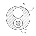
- the II-II cross-sectional view of the balloon catheter shown in FIG. 1 is shown.
- a cross-sectional view taken along the longitudinal direction of a second balloon catheter according to an embodiment of the present invention is shown.
- the IV-IV cross-sectional view of the balloon catheter shown in FIG. 3 is shown.
- a cross-sectional view perpendicular to the longitudinal direction of the second shaft of the balloon catheter according to another embodiment of the present invention is shown.
- FIG. 1 is a cross-sectional view taken along the longitudinal direction of the first balloon catheter 1 according to the embodiment of the present invention
- FIG. 2 is a cross section of II-II perpendicular to the longitudinal direction of the balloon catheter 1 shown in FIG. It is a figure.
- the balloon catheter 1 of the present invention includes a first shaft 10 having a first lumen 11 and a second lumen 12, and a second shaft 20 arranged on the distal side of the first shaft 10.
- the balloon 30 is arranged on the distal side of the second shaft 20, and the optical fiber 40 is arranged on the inner side of the balloon 30, and the optical fiber 40 is the distal end of the first lumen 11.
- the material constituting the first shaft 10 is a resin, and as shown in FIG. 2, the cross-sectional areas of the resin forming the first shaft 10 in the cross section perpendicular to the longitudinal direction are the first lumen 11 and the first.
- the cross-sectional area of 2 lumens 12 is larger than the cross-sectional area of either one. That is, of the cross-sectional area of the first lumen 11 and the cross-sectional area of the second lumen 12, the cross-sectional area of the resin forming the first shaft 10 is larger than the larger cross-sectional area. In other words, the cross-sectional area of the resin forming the first shaft 10 is larger than the cross-sectional area of either the first lumen 11 or the second lumen 12.
- the cross-sectional area of the resin forming the first shaft 10 is larger than the cross-sectional area of either the first rumen 11 and the second rumen 12 having a large cross-sectional area, and the optical fiber 40 is the first.
- the balloon is joined to the distal end 11d of the lumen 11, the proximal end 30p of the balloon 30 is joined to the second shaft 20, and the distal end 30d of the balloon 30 is joined to the optical fiber 40. Since the proximal end 30p of the 30 is connected to the first shaft 10 via the second shaft 20, and the distal end 30d of the balloon 30 is connected to the first shaft 10 via the optical fiber 40.
- the pulling force of the first shaft 10 is easily transmitted to both the proximal end 30p and the distal end 30d of the balloon 30. Therefore, it is possible to improve the removability when the balloon catheter 1 is removed from an endoscope or the like.
- the optical fiber 40 is joined to the distal end 11d of the first lumen 11, the proximal end 30p of the balloon 30 is joined to the second shaft 20, and the distal end 30d of the balloon 30 is joined to the optical fiber 40.
- the optical fiber 40 is joined to the distal end 11d of the first lumen 11 which is proximal to the proximal end 30p of the balloon 30. Therefore, in the longitudinal direction of the balloon catheter 1, the optical fiber 40 is not fixed to another object between the distal end 30d of the balloon 30 and the distal end 11d of the first lumen 11, and the balloon catheter 1 is adjusted to the bent state.
- the balloon 40 can be freely repositioned and bent.
- the optical fiber 40 can be arranged at the center of the cross section of the balloon 30 perpendicular to the longitudinal direction, which facilitates photodynamic therapy. be able to.
- the proximal end 30p of the balloon 30 is preferably joined to the distal end 20d of the second shaft 20, and the distal end 30d of the balloon 30 is joined to the distal end 40d of the optical fiber 40. preferable.
- the bonding between the optical fiber 40 and the first lumen 11, the bonding between the balloon 30 and the second shaft 20, and the bonding between the balloon 30 and the optical fiber 40 may be directly bonded to each other, or may be bonded via other members. It may have been done.
- Examples of the joining of the optical fiber 40 and the first lumen 11, the joining of the balloon 30 and the second shaft 20, and the joining of the balloon 30 and the optical fiber 40 include methods such as welding and adhesion.
- the proximal side refers to the user, that is, the operator's hand side with respect to the longitudinal direction of the first shaft 10
- the distal side refers to the direction opposite to the proximal side, that is, the treatment target side. ..
- the direction from the proximal side to the distal side of the first shaft 10 or the direction from the distal side to the proximal side is referred to as a longitudinal direction.
- the longitudinal direction can be rephrased as the perspective direction of the first shaft 10.
- the first shaft 10 extends in the longitudinal direction and has a tubular structure including a first lumen 11 and a second lumen 12.
- first lumen 11 the distal end 11d of the first lumen 11 is joined to the optical fiber 40, and the optical fiber 40 can be arranged inside the first lumen 11.
- the second lumen 12 communicates with the lumen of the balloon 30 and can serve as a path for supplying fluid to the inside of the balloon 30.
- the junction between the distal end 11d of the first lumen 11 and the optical fiber 40 does not have a gap in which the first lumen 11 and the outside of the first lumen 11 communicate with each other. That is, the optical fiber 40 is preferably joined so as to seal the distal end 11d of the first lumen 11.
- the junction between the distal end 11d of the first lumen 11 and the optical fiber 40 is supplied through the second lumen 12 because it does not have a gap in which the first lumen 11 and the outside of the first lumen 11 communicate with each other. Prevents the fluid from entering the first lumen 11.
- the balloon 30 can be expanded quickly, the time required for expansion of the balloon 30 can be shortened, and the procedure time can be shortened.
- the first shaft 10 may include at least the first lumen 11 and the second lumen 12, and may further have lumens different from those of the first lumen 11 and the second lumen 12.
- the first shaft 10 preferably has flexibility. Since the first shaft 10 has flexibility, the first shaft 10 becomes flexible and easy to bend. Therefore, the balloon catheter 1 can be easily inserted into the body.
- the material constituting the first shaft 10 is a resin, and as shown in FIG. 2, the cross-sectional areas of the resin forming the first shaft 10 in the cross section perpendicular to the longitudinal direction are the first lumen 11 and the second lumen 12.
- the cross-sectional area of is larger than the cross-sectional area of either one.
- the cross-sectional area of the second lumen 12 is larger than the cross-sectional area of the first lumen 11, the cross-sectional area of the second lumen 12 and the first shaft 10 are formed. Compare with the cross-sectional area of the resin to be used.
- first shaft 10 When the cross-sectional area of the first lumen 11 and the cross-sectional area of the second lumen 12 are the same, either the cross-sectional area of the first lumen 11 or the cross-sectional area of the second lumen 12 is used as the first shaft 10. It may be used for comparison with the cross-sectional area of the resin to be formed.
- the rigidity of the first shaft 10 can be increased by having the cross-sectional area of the resin forming the first shaft 10 larger than the cross-sectional area of either the first lumen 11 and the second lumen 12 having a large cross-sectional area. ..
- the cross-sectional area of the resin forming the first shaft 10 is 1.1 times or more the cross-sectional area of either one having a large cross-sectional area of the first lumen 11 and the second lumen 12. Is preferable, 1.2 times or more is more preferable, and 1.3 times or more is further preferable.
- the first It is possible to sufficiently increase the rigidity of 1 shaft 10.
- the cross-sectional area of the resin forming the first shaft 10 is preferably 5 times or less, preferably 4 times or less, the cross-sectional area of either one having a large cross-sectional area of the first lumen 11 and the second lumen 12. More preferably, it is more preferably 3 times or less.
- the material constituting the first shaft 10 is, for example, a polyolefin resin such as polyethylene or polypropylene, a polyamide resin such as nylon, a polyester resin such as PET, an aromatic polyether ketone resin such as PEEK, or a vinyl chloride resin. , Polyether polyamide resin, polyurethane resin, polyimide resin, synthetic resin such as fluorine resin such as PTFE, PFA, ETFE and the like. These may be used alone or in combination of two or more. Above all, the material constituting the first shaft 10 preferably contains a polyolefin-based resin, a polyamide-based resin, and a fluorine-based resin.
- the material constituting the first shaft 10 contains a polyolefin resin, a polyamide resin, and a fluorine resin, the first shaft 10 has flexibility and the surface of the first shaft 10 is slippery. Therefore, the balloon catheter 1 having good insertability can be obtained.
- the second shaft 20 has a tubular structure extending in the longitudinal direction and having a lumen.
- the second shaft 20 is arranged on the distal side of the first shaft 10. That is, the second shaft 20 is arranged on the distal side of the distal end 10d of the first shaft 10.
- An optical fiber 40 is arranged in the lumen of the second shaft 20.
- the second shaft 20 preferably has flexibility. Since the second shaft 20 has flexibility, the second shaft 20 becomes flexible, and the insertability of the balloon catheter 1 can be improved.
- the second shaft 20 may be composed of a plurality of members, but is preferably composed of one tubular member. Since the second shaft 20 is composed of one tubular member, the second shaft 20 becomes flexible. As a result, when the balloon catheter 1 is inserted into the bent internal lumen, the second shaft 20 is easily bent, and the insertability of the balloon catheter 1 can be improved.
- the material constituting the second shaft 20 is, for example, a polyolefin resin such as polyethylene or polypropylene, a polyamide resin such as nylon, a polyester resin such as PET, an aromatic polyether ketone resin such as PEEK, or a vinyl chloride resin. , Polyether polyamide resin, polyurethane resin, polyimide resin, synthetic resin such as fluorine resin such as PTFE, PFA, ETFE, metal such as stainless steel, carbon steel, nickel titanium alloy and the like. These may be used alone or in combination of two or more. Above all, it is preferable that the material constituting the second shaft 20 contains the same material as the material constituting the first shaft 10.
- the material constituting the second shaft 20 contains the same material as the material constituting the first shaft 10, the physical properties such as hardness and surface slipperiness of the first shaft 10 and the second shaft 20 are close to each other. Therefore, the balloon catheter 1 can be easily inserted into the body. Further, when the first shaft 10 and the second shaft 20 are directly joined, the joining strength between the first shaft 10 and the second shaft 20 can be increased.
- the balloon 30 is arranged on the distal side of the second shaft 20. That is, the balloon 30 is arranged distal to the distal end 20d of the second shaft 20. Further, the proximal end 30p of the balloon 30 is joined to the second shaft 20, and the distal end 30d of the balloon 30 is joined to the optical fiber 40. The proximal end 30p of the balloon 30 is preferably joined to the distal end 20d of the second shaft 20.
- the balloon 30 is configured so that fluid is supplied from the fluid feeder to the inside of the balloon 30 through the first shaft 10 and the second shaft 20.
- the balloon 30 can be expanded.
- the balloon 30 can be contracted by removing the fluid inside the balloon 30 from the balloon 30.
- the fluid supplied to the inside of the balloon 30 may be a pressure fluid pressurized by a pump or the like.
- the type of fluid supplied into the balloon 30 for example, a liquid such as physiological saline, a contrast medium, or a mixed solution thereof, or a gas such as air, nitrogen, or carbon dioxide can be used.
- the fluid supplied into the balloon 30 is preferably a gas. Since the fluid supplied into the balloon 30 is a gas, the fluid existing in the balloon 30 interferes with the emission light of the optical fiber 40 arranged inside the balloon 30 when performing photodynamic therapy. It becomes difficult.
- the balloon 30 preferably has a straight tube portion 31. Since the balloon 30 has the straight tube portion 31, the area where the balloon 30 and the luminal wall in the body are in contact with each other can be increased. Therefore, the balloon 30 can be fixed in the lumen of the body, and photodynamic therapy can be easily performed.
- the balloon 30 is located at the proximal taper portion connected to the straight tube portion 31 on the proximal side of the proximal end 31p of the straight tube portion 31 and on the distal side of the distal end 31d of the straight tube portion 31. It has a distal taper portion connected to the straight pipe portion 31, and the proximal taper portion and the distal taper portion are formed so as to decrease in diameter as the distance from the straight pipe portion 31 increases. preferable.
- the proximal side tapered portion and the distal side tapered portion formed so that the diameter of the balloon 30 decreases as the distance from the straight tube portion 31 increases, the strength of the balloon 30 can be increased, and the balloon can be increased.
- the balloon 30 can be prevented from being damaged when a force is applied to the 30. Further, since the step generated when the balloon 30 is wound around the shaft can be reduced, the balloon 30 can be easily inserted into the lumen in the body.
- the balloon 30 can be configured so that the distal taper portion swells from the proximal taper portion through the straight pipe portion 31 when a fluid is supplied.
- the inflatable portion is regarded as the balloon 30.
- the material constituting the balloon 30 is, for example, a polyolefin resin such as polyethylene, polypropylene or an ethylene-propylene copolymer, a polyester resin such as polyethylene terephthalate or a polyester elastomer, a polyurethane resin such as polyurethane or a polyurethane elastomer, or a polyphenylene sulfide type.
- a polyolefin resin such as polyethylene, polypropylene or an ethylene-propylene copolymer
- a polyester resin such as polyethylene terephthalate or a polyester elastomer
- a polyurethane resin such as polyurethane or a polyurethane elastomer
- a polyphenylene sulfide type examples thereof include polyamide resins such as resins, polyamides and polyamide elastomers, vinyl chloride resins, fluororesins, silicone resins, and natural rubbers such as latex rubber. Only one of
- the material constituting the balloon 30 is preferably a polyamide resin, a polyester resin, or a polyurethane resin.
- the material constituting the balloon 30 is a polyamide resin, a polyester resin, or a polyurethane resin, the balloon 30 can be made thinner and its flexibility can be improved.
- the optical fiber 40 extends in the longitudinal direction. Further, the optical fiber 40 is arranged inside the balloon 30 and is joined to the distal end 11d of the first lumen 11.
- the optical fiber 40 is a transmission line that transmits an optical signal to the target tissue.
- the optical fiber 40 is connected to a light source such as a semiconductor laser by a connector or the like provided at the proximal end.
- the optical fiber 40 has a core and a cladding that covers the radial outer side of the core.
- synthetic resin such as fluorine-based resin and acrylic resin
- glass such as quartz glass and fluoride glass
- the optical fiber 40 preferably has a clad non-existent portion in a part of the distal portion of the core.
- the non-existing portion of the clad refers to a portion where the clad does not exist in at least a part in the circumferential direction of the core, and serves as a light emitting area of the optical fiber 40. Since the optical fiber 40 has a non-existent portion of the clad, it is a side irradiation type and can form a balloon catheter 1 used for photodynamic therapy.
- the position where the non-existing portion of the clad is provided in the longitudinal direction is not particularly limited as long as it is a part of the distal portion of the core, but it is preferably provided in the portion including the distal end of the core. Since the non-existent portion of the clad is provided in the portion including the distal end of the core, the non-existent portion of the clad is easily formed.
- the non-existent portion of the clad can be formed by peeling the clad by, for example, etching or polishing. Further, it is more preferable to roughen the outer surface of the non-existing portion of the clad by a method such as sanding. The light diffusivity can be improved by roughening the outer surface of the non-existent portion of the clad.
- the optical fiber 40 may further have a covering material.
- the material constituting the coating material is, for example, a polyolefin resin such as polyethylene or polypropylene, a polyamide resin such as nylon, or the like.
- Polyester resin such as PET, aromatic polyetherketone resin such as PEEK, vinyl chloride resin, polyether polyamide resin, polyurethane resin, polyimide resin, fluorinated resin such as PTFE, PFA, ETFE, etc. Is preferable.
- the balloon catheter 1 Since the balloon catheter 1 has the optical fiber 40 and the optical fiber 40 is arranged inside the balloon 30, the light emitted from the balloon 40 is likely to be directed to the straight tube portion 31 of the balloon 30. Therefore, it becomes easy to irradiate the target tissue with the light used for photodynamic therapy through the optical fiber 40, and the photodynamic therapy can be efficiently performed.
- the distal end 40d of the optical fiber 40 is preferably located distal to the distal end 30d of the balloon 30. Since the distal end 40d of the optical fiber 40 is distal to the distal end 30d of the balloon 30, the rigidity of the distal end of the balloon catheter 1 is increased. Therefore, it becomes easy to insert the balloon catheter 1 into the body. Further, since the distal end 40d of the optical fiber 40 is on the distal side of the distal end 30d of the balloon 30, the optical fiber 40 is present over the entire length of the balloon 30 in the longitudinal direction. As a result, the optical fiber 40 can be present in the entire straight tube portion 31 of the balloon 30 in the longitudinal direction, which facilitates photodynamic therapy.
- the amount of light at the cutting edge of the optical fiber 40 is weakened, and the amount of light may not be sufficient for performing photodynamic therapy.
- the distal end 40d of the optical fiber 40 is located distal to the straight tube 31 of the balloon 30 or distal to the distal taper of the balloon 30. It is preferable to have.
- the distal end 40d of the optical fiber 40 is located distal to the straight tube 31 of the balloon 30 and distal to the distal taper to ensure a sufficient amount of light in photodynamic therapy. Can be done.
- a covering material is appropriately arranged on the optical fiber 40 or the like. It is possible to irradiate a desired site with light.
- the distal end 40d of the optical fiber 40 is preferably located distal to the distal taper of the balloon 30. Since the distal end 40d of the optical fiber 40 is on the distal side of the distal taper portion of the balloon 30, a sufficient amount of light in photodynamic therapy can be secured. Further, since the distal end 40d of the optical fiber 40 is on the distal side of the distal end 30d of the balloon 30, the rigidity of the distal end of the balloon catheter 1 is increased. Therefore, it becomes easy to insert the balloon catheter 1 into the body.
- the balloon catheter 1 preferably has a handle portion on the proximal side.
- the handle portion preferably has a lumen extending in the longitudinal direction that communicates with the first lumen 11.
- the lumen that the handle portion has and communicates with the first lumen 11 can be used as an insertion passage for the optical fiber 40 or the like.
- the handle portion includes a fluid injection portion and has a lumen communicating with the second lumen 12.
- the lumen that the handle portion has and communicates with the second lumen 12 can be used as a fluid supply and removal path for expanding the balloon 30.
- the proximal end 20p of the second shaft 20 is preferably joined to the distal end 10d of the first shaft 10. That is, it is preferable that the first shaft 10 and the second shaft 20 are directly joined. Since the proximal end 20p of the second shaft 20 is joined to the distal end 10d of the first shaft 10, the second shaft 20 can be easily joined to the first shaft 10. As a result, the efficiency of manufacturing the balloon catheter 1 can be improved.
- FIG. 3 is a cross-sectional view taken along the longitudinal direction of the second balloon catheter 1 according to the embodiment of the present invention
- FIG. 4 is an IV-IV perpendicular to the longitudinal direction of the balloon catheter 1 shown in FIG. It is a cross-sectional view.
- the first shaft 10 of the balloon catheter 1 includes an inner cylinder portion 50 having a first lumen 11 and a second lumen portion 12, and is provided on the outer surface of the inner cylinder portion 50. At least a part is fixed to the inner surface of the first shaft 10.
- the first shaft 10 includes an inner cylinder portion 50 having a first lumen 11 and a second lumen 12, and at least a part of the outer surface of the inner cylinder portion 50 is fixed to the inner surface of the first shaft 10, and an optical fiber is used.
- 40 is joined to the distal end 50d of the inner cylinder 50, the proximal end 30p of the balloon 30 is joined to the second shaft 20, and the distal end 30d of the balloon 30 is joined to the optical fiber 40.
- the proximal end 30p of the balloon 30 is connected to the first shaft 10 via the second shaft 20, and the distal end 30d of the balloon 30 is connected to the first shaft 10 via the optical fiber 40. It becomes.
- the force that pulls the first shaft 10 toward the hand side is easily transmitted to both the distal end 30d and the proximal end 30p of the balloon 30, and the balloon catheter 1 is removed.
- the sex can be improved.
- the proximal end 30p of the balloon 30 is preferably joined to the distal end 20d of the second shaft 20, and the distal end 30d of the balloon 30 is joined to the distal end 40d of the optical fiber 40. Is preferable.
- the optical fiber 40 is joined to the distal end 50d of the inner cylinder portion 50, the proximal end 30p of the balloon 30 is joined to the second shaft 20, and the distal end 30d of the balloon 30 is joined to the optical fiber 40. Therefore, in the longitudinal direction of the balloon catheter 1, the optical fiber 40 is not fixed to another object between the distal end 30d of the balloon 30 and the distal end 11d of the first lumen 11, and the optical fiber 40 is a balloon catheter. It is possible to freely change the position or bend according to the bending state of 1. Therefore, when performing photodynamic therapy for irradiating the target tissue with light, the optical fiber 40 can be arranged at the center of the cross section of the balloon 30 perpendicular to the longitudinal direction, which facilitates photodynamic therapy.
- the inner cylinder portion 50 extends in the longitudinal direction.
- An optical fiber 40 is inserted into the lumen of the inner cylinder portion 50.
- Examples of the method of fixing at least a part of the outer surface of the inner cylinder portion 50 to the inner surface of the first shaft 10 include welding, adhesion, fixing via other parts, and the like.
- the length L1 of the second shaft 20 in the longitudinal direction is preferably 10 times or more the minimum outer diameter of the second shaft 20.
- the length L1 of the second shaft 20 in the longitudinal direction indicates the distance between the distal end 20d of the second shaft 20 and the proximal end 20p of the second shaft 20 in the longitudinal direction. Since the length L1 of the second shaft 20 is 10 times or more the minimum outer diameter of the second shaft 20, the length L1 of the second shaft 20 can be made sufficient and is joined to the optical fiber 40. The distance from the distal end 30d of the balloon 30 to the distal end 11d of the first lumen 11 joined to the optical fiber 40 can be increased.
- the distance between the two points where the optical fiber 40 is joined to another object can be separated, and the optical fiber 40 can freely adjust to the bent state of the balloon catheter 1 in the portion where the optical fiber 40 is not bonded to another object. It is possible to change the position and bend. As a result, the optical fiber 40 is located at the center of the cross section of the balloon 30 perpendicular to the longitudinal direction, and photodynamic therapy can be efficiently performed.
- the length L1 of the second shaft 20 in the longitudinal direction is preferably 10 times or more the minimum outer diameter of the second shaft 20, and more preferably 11 times or more the minimum outer diameter of the second shaft 20. It is more preferable that the diameter is 12 times or more the minimum outer diameter of the second shaft 20.
- the optical fiber 40 is formed from the distal end 30d of the balloon 30 joined to the optical fiber 40. The distance to the distal end 11d of the first lumen 11 joined to can be sufficiently separated.
- the upper limit of the ratio between the length L1 of the second shaft 20 and the minimum outer diameter of the second shaft 20 can be, for example, 600 times or less, 400 times or less, and 200 times or less.
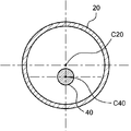
- the position of the central axis C20 of the outer shape of the second shaft 20 and the position of the central axis C40 of the outer shape of the optical fiber 40 is preferably different. Since the position of the central axis C20 of the outer shape of the second shaft 20 and the position of the central axis C40 of the outer shape of the optical fiber 40 are different, the optical fiber 40 is free in the respective lumens of the second shaft 20 and the balloon 30. It becomes easier to change the position and bend.
- the optical fiber 40 easily moves according to the bent state of the balloon catheter 1, and the optical fiber 40 is located at the center of the cross section of the balloon 30 perpendicular to the longitudinal direction. It will be easier. As a result, photodynamic therapy becomes easier to perform.
- the cross-sectional area of the gap portion formed by the inner surface of the second shaft 20 and the outer surface of the optical fiber 40 is the cross section of the second shaft 20. It is preferably 40% or more of the cross-sectional area of the lumen.
- the cross-sectional area of the gap formed between the inner surface of the second shaft 20 and the outer surface of the optical fiber 40 is 40% or more of the cross-sectional area of the lumen of the second shaft 20, the inside of the second shaft 20
- the optical fiber 40 can move freely. Therefore, even when the second shaft 20 is bent, the optical fiber 40 is likely to be located at the center of the cross section of the balloon 30 perpendicular to the longitudinal direction, which facilitates photodynamic therapy.
- the cross-sectional area of the gap formed by the inner surface of the second shaft 20 and the outer surface of the optical fiber 40 is 40, which is the cross-sectional area of the lumen of the second shaft 20. % Or more, more preferably 45% or more, and even more preferably 50% or more.
- the upper limit of the ratio between the cross-sectional area of the gap formed by the inner surface of the second shaft 20 and the outer surface of the optical fiber 40 and the cross-sectional area of the lumen of the second shaft 20 is, for example, 99% or less. , 97% or less, 95% or less.
- FIG. 5 is a cross-sectional view perpendicular to the longitudinal direction of the second shaft 20 of the balloon catheter 1 according to another embodiment of the present invention.
- the inner surface of the second shaft 20 has a protrusion 70 that comes into contact with the outer surface of the optical fiber 40.
- the protrusion 70 can determine the position of the optical fiber 40 in the second shaft 20.
- the position of the optical fiber 40 can be regulated so as not to deviate significantly from the central axis of the balloon 30.
- the protrusion 70 is not joined to the optical fiber 40.
- the protrusion 70 is preferably arranged on the inner surface of the distal end of the second shaft 20.
- a protrusion 70 that contacts the outer surface of the optical fiber 40 is placed on the inner surface of the distal end of the second shaft 20 so that the optical fiber 40 is located at the center of the second shaft 20 in a cross section perpendicular to the longitudinal direction.
- the position of the optical fiber 40 at the distal end of the second shaft 20 is likely to be located at the center of the second shaft 20.
- the position of the optical fiber 40 is easily arranged in the center of the balloon 30 even in the lumen of the balloon 30 which is arranged on the distal side of the second shaft 20 and is joined to the second shaft 20, and the light beam.
- the balloon catheter 1 can be used for easy dynamic therapy.
- the number of protrusions 70 arranged on the inner surface of the second shaft 20 is preferably a plurality. Since the number of protrusions 70 is plural, the position of the optical fiber 40 in the second shaft 20 can be easily regulated by the protrusions 70.
- the tip 60 is arranged on the distal side of the optical fiber 40, and the distal end 60d of the tip 60 is distal to the distal end 30d of the balloon 30. Is preferable. Since the distal end 60d of the tip tip 60 is distal to the distal end 30d of the balloon 30, the rigidity of the distal end of the balloon catheter 1 is increased. As a result, the insertability of the balloon catheter 1 can be improved.
- the color of the tip 60 is preferably different from the color of the optical fiber 40.
- the difference between the color of the tip chip 60 and the color of the optical fiber 40 means that at least one of the hue, lightness, and saturation defined in JIS Z8721 is different. Since the color of the tip tip 60 is different from the color of the optical fiber 40, the tip tip 60 is easily visible under an endoscope. As a result, the positions of the tip tip 60 and the balloon 30 can be easily confirmed in the lumen of the body.
- the balloon catheter of the present invention has a first shaft having a first lumen and a second lumen, a second shaft arranged on the distal side of the first shaft, and a distal side of the second shaft. It has a balloon arranged in the balloon and an optical fiber arranged inside the balloon, and the material constituting the first shaft is a resin, which is the first in a cross section perpendicular to the longitudinal direction.
- the cross-sectional area of the resin forming the shaft is larger than the cross-sectional area of either the first rumen or the second rumen, which has a larger cross-sectional area, and the optical fiber is joined to the distal end of the first rumen of the balloon.
- the proximal end is joined to the second shaft and the distal end of the balloon is joined to the optical fiber.
- the cross-sectional area of the resin forming the first shaft in the longitudinally perpendicular section is larger than the cross-sectional area of either the first rumen or the second lumen, which has a larger cross-sectional area, and the optical fiber is located at the distal end of the first rumen. It is joined, the proximal end of the balloon is joined to the second shaft, and the distal end of the balloon is joined to the optical fiber so that the force applied to the balloon catheter is far from the proximal end of the balloon. Easy to convey to both ends. Therefore, it is possible to improve the removability of the balloon catheter from an endoscope or the like.
- the optical fiber is joined to the distal end of the first lumen, which is proximal to the proximal end of the balloon, rather than the proximal end of the balloon, the first lumen from the distal end of the balloon in the longitudinal direction.
- the optical fiber is not fixed to anything else up to the distal end of the fracture and can move freely.
- An optical fiber can be arranged in the part, which makes it easier to perform photodynamic therapy.
- the second balloon catheter of the present invention includes an inner cylinder portion having a first lumen, a first shaft including a second lumen, and a second shaft arranged on the distal side of the first shaft.
- a balloon arranged on the distal side of the second shaft and an optical fiber arranged on the inner side of the balloon, and at least a part of the outer surface of the inner cylinder portion of the first shaft Fixed to the inner surface, the optical fiber is joined to the distal end of the inner cylinder, the proximal end of the balloon is joined to the second shaft, and the distal end of the balloon is joined to the optical fiber. Has been done.
- the first shaft has an inner cylinder portion having a first lumen and a second lumen, and at least a part of the outer surface of the inner cylinder portion is fixed to the inner surface of the first shaft, and the optical fiber is far from the inner cylinder portion. It is joined to the position end, the proximal end of the balloon is joined to the second shaft, and the distal end of the balloon is joined to the optical fiber, so that when removing the balloon catheter from an endoscope or the like.
- the pulling force of the balloon catheter is easily transmitted to the proximal and distal ends of the balloon, making it easier to remove the balloon catheter from an endoscope or the like.
- the optical fiber since the optical fiber is joined to the distal end of the first lumen, the optical fiber can move freely from the distal end of the balloon in the longitudinal direction to the distal end of the first lumen. Therefore, even when the shaft of the balloon catheter is bent or the balloon is compressed, the optical fiber can be arranged at the center of the cross section of the balloon perpendicular to the longitudinal direction.
- Balloon catheter 10 1st shaft 10d: Distal end of 1st shaft 11: 1st lumen 11d: Distal end of 1st lumen 11p: Proximal end of 1st lumen 12: 2nd lumen 20: 2nd Shaft 20d: Distal end of second shaft 20p: Proximal end of second shaft 30: Balloon 30d: Distal end of balloon 30p: Proximal end of balloon 31: Straight tube 31d: Distal end of straight tube 31p: Proximal end of straight tube 40: Optical fiber 40d: Distal end of optical fiber 50: Inner cylinder 50d: Distal end of inner cylinder 60: Tip tip 60d: Distal end of tip tip 70: Protrusion L1: Length of 2nd shaft C20: Central axis of outer shape of 2nd shaft C40: Central axis of outer shape of optical fiber
Landscapes
- Health & Medical Sciences (AREA)
- Life Sciences & Earth Sciences (AREA)
- Engineering & Computer Science (AREA)
- Biomedical Technology (AREA)
- Animal Behavior & Ethology (AREA)
- Veterinary Medicine (AREA)
- Public Health (AREA)
- General Health & Medical Sciences (AREA)
- Heart & Thoracic Surgery (AREA)
- Nuclear Medicine, Radiotherapy & Molecular Imaging (AREA)
- Biophysics (AREA)
- Pathology (AREA)
- Radiology & Medical Imaging (AREA)
- Hematology (AREA)
- Anesthesiology (AREA)
- Pulmonology (AREA)
- Child & Adolescent Psychology (AREA)
- Physics & Mathematics (AREA)
- Optics & Photonics (AREA)
- Laser Surgery Devices (AREA)
- Media Introduction/Drainage Providing Device (AREA)
- Radiation-Therapy Devices (AREA)
Priority Applications (3)
| Application Number | Priority Date | Filing Date | Title |
|---|---|---|---|
| US17/908,682 US20230118963A1 (en) | 2020-03-06 | 2021-02-24 | Balloon catheter |
| JP2022505141A JP7605822B2 (ja) | 2020-03-06 | 2021-02-24 | バルーンカテーテル |
| CN202180017785.1A CN115243752B (zh) | 2020-03-06 | 2021-02-24 | 球囊导管 |
Applications Claiming Priority (2)
| Application Number | Priority Date | Filing Date | Title |
|---|---|---|---|
| JP2020-039082 | 2020-03-06 | ||
| JP2020039082 | 2020-03-06 |
Publications (1)
| Publication Number | Publication Date |
|---|---|
| WO2021177103A1 true WO2021177103A1 (ja) | 2021-09-10 |
Family
ID=77613520
Family Applications (1)
| Application Number | Title | Priority Date | Filing Date |
|---|---|---|---|
| PCT/JP2021/006827 Ceased WO2021177103A1 (ja) | 2020-03-06 | 2021-02-24 | バルーンカテーテル |
Country Status (4)
| Country | Link |
|---|---|
| US (1) | US20230118963A1 (https=) |
| JP (1) | JP7605822B2 (https=) |
| CN (1) | CN115243752B (https=) |
| WO (1) | WO2021177103A1 (https=) |
Citations (5)
| Publication number | Priority date | Publication date | Assignee | Title |
|---|---|---|---|---|
| US6755849B1 (en) * | 2002-03-28 | 2004-06-29 | Board Of Regents, The University Of Texas System | Method for delivering energy to tissue and apparatus |
| JP2004344627A (ja) * | 2003-05-22 | 2004-12-09 | Tomio Wada | 治療用バルーンカテーテル |
| JP2005534409A (ja) * | 2002-08-05 | 2005-11-17 | ミラヴァント メディカル テクノロジーズ,インコーポレーテッド | 光伝達カテーテル |
| JP2008264134A (ja) * | 2007-04-18 | 2008-11-06 | Kaneka Corp | バルーンカテーテル |
| JP2012183127A (ja) * | 2011-03-04 | 2012-09-27 | Asahi Intecc Co Ltd | バルーンカテーテル |
Family Cites Families (9)
| Publication number | Priority date | Publication date | Assignee | Title |
|---|---|---|---|---|
| US5090959A (en) * | 1987-04-30 | 1992-02-25 | Advanced Cardiovascular Systems, Inc. | Imaging balloon dilatation catheter |
| US5029574A (en) | 1988-04-14 | 1991-07-09 | Okamoto Industries, Inc. | Endoscopic balloon with a protective film thereon |
| JPH0330760A (ja) * | 1989-06-29 | 1991-02-08 | Fujitsu Ltd | レーザ光照射ヘッド |
| US5304171A (en) * | 1990-10-18 | 1994-04-19 | Gregory Kenton W | Catheter devices and methods for delivering |
| JPH0889499A (ja) * | 1994-09-29 | 1996-04-09 | Terumo Corp | カテーテル |
| US5997571A (en) * | 1997-12-17 | 1999-12-07 | Cardiofocus, Inc. | Non-occluding phototherapy probe stabilizers |
| US7329223B1 (en) * | 2001-05-31 | 2008-02-12 | Abbott Cardiovascular Systems Inc. | Catheter with optical fiber sensor |
| US20030208221A1 (en) * | 2002-05-02 | 2003-11-06 | Fozan El-Nounou | Catheter with a coiled support member |
| US7063679B2 (en) * | 2002-09-20 | 2006-06-20 | Flowmedica, Inc. | Intra-aortic renal delivery catheter |
-
2021
- 2021-02-24 CN CN202180017785.1A patent/CN115243752B/zh active Active
- 2021-02-24 JP JP2022505141A patent/JP7605822B2/ja active Active
- 2021-02-24 US US17/908,682 patent/US20230118963A1/en active Pending
- 2021-02-24 WO PCT/JP2021/006827 patent/WO2021177103A1/ja not_active Ceased
Patent Citations (5)
| Publication number | Priority date | Publication date | Assignee | Title |
|---|---|---|---|---|
| US6755849B1 (en) * | 2002-03-28 | 2004-06-29 | Board Of Regents, The University Of Texas System | Method for delivering energy to tissue and apparatus |
| JP2005534409A (ja) * | 2002-08-05 | 2005-11-17 | ミラヴァント メディカル テクノロジーズ,インコーポレーテッド | 光伝達カテーテル |
| JP2004344627A (ja) * | 2003-05-22 | 2004-12-09 | Tomio Wada | 治療用バルーンカテーテル |
| JP2008264134A (ja) * | 2007-04-18 | 2008-11-06 | Kaneka Corp | バルーンカテーテル |
| JP2012183127A (ja) * | 2011-03-04 | 2012-09-27 | Asahi Intecc Co Ltd | バルーンカテーテル |
Also Published As
| Publication number | Publication date |
|---|---|
| JP7605822B2 (ja) | 2024-12-24 |
| CN115243752B (zh) | 2024-08-27 |
| JPWO2021177103A1 (https=) | 2021-09-10 |
| CN115243752A (zh) | 2022-10-25 |
| US20230118963A1 (en) | 2023-04-20 |
Similar Documents
| Publication | Publication Date | Title |
|---|---|---|
| US9199058B2 (en) | Multifilar cable catheter | |
| CN103096964B (zh) | 弯曲导管 | |
| JP7384814B2 (ja) | 光照射医療装置 | |
| US20120053419A1 (en) | Highly Articulable Catheter | |
| US20220161046A1 (en) | Catheter and light irradiation system | |
| CN113453742B (zh) | 球囊阻断导管 | |
| JP4101323B2 (ja) | 医療用チューブ | |
| JP7346134B2 (ja) | カテーテル、及び、光照射システム | |
| US12415088B2 (en) | Light irradiation device and light irradiation system | |
| US12515068B2 (en) | Balloon catheter | |
| US20150088152A1 (en) | Elongated member for medical use | |
| WO2021177103A1 (ja) | バルーンカテーテル | |
| WO2020195720A1 (ja) | 医療用管状体搬送装置およびその製造方法 | |
| JP2024051066A (ja) | バルーンカテーテル | |
| US20240082551A1 (en) | Catheter | |
| JP7329042B2 (ja) | 医療用管状体搬送装置 | |
| WO2023171064A1 (ja) | カテーテル | |
| JP2025088498A (ja) | カテーテルセット及びガイド管部材交換方法 | |
| JP2025119195A (ja) | 医療機器用補助具、ガイドワイヤアッセンブリ及び医療機器アッセンブリ | |
| WO2023095838A1 (ja) | カテーテル | |
| WO2024262528A1 (ja) | バルーンカテーテル | |
| WO2021090425A1 (ja) | カテーテル |
Legal Events
| Date | Code | Title | Description |
|---|---|---|---|
| 121 | Ep: the epo has been informed by wipo that ep was designated in this application |
Ref document number: 21763767 Country of ref document: EP Kind code of ref document: A1 |
|
| ENP | Entry into the national phase |
Ref document number: 2022505141 Country of ref document: JP Kind code of ref document: A |
|
| NENP | Non-entry into the national phase |
Ref country code: DE |
|
| 122 | Ep: pct application non-entry in european phase |
Ref document number: 21763767 Country of ref document: EP Kind code of ref document: A1 |