WO2021177103A1 - Balloon catheter - Google Patents
Balloon catheter Download PDFInfo
- Publication number
- WO2021177103A1 WO2021177103A1 PCT/JP2021/006827 JP2021006827W WO2021177103A1 WO 2021177103 A1 WO2021177103 A1 WO 2021177103A1 JP 2021006827 W JP2021006827 W JP 2021006827W WO 2021177103 A1 WO2021177103 A1 WO 2021177103A1
- Authority
- WO
- WIPO (PCT)
- Prior art keywords
- shaft
- balloon
- optical fiber
- lumen
- distal end
- Prior art date
Links
Images


Classifications
-
- A—HUMAN NECESSITIES
- A61—MEDICAL OR VETERINARY SCIENCE; HYGIENE
- A61M—DEVICES FOR INTRODUCING MEDIA INTO, OR ONTO, THE BODY; DEVICES FOR TRANSDUCING BODY MEDIA OR FOR TAKING MEDIA FROM THE BODY; DEVICES FOR PRODUCING OR ENDING SLEEP OR STUPOR
- A61M25/00—Catheters; Hollow probes
- A61M25/10—Balloon catheters
-
- A—HUMAN NECESSITIES
- A61—MEDICAL OR VETERINARY SCIENCE; HYGIENE
- A61N—ELECTROTHERAPY; MAGNETOTHERAPY; RADIATION THERAPY; ULTRASOUND THERAPY
- A61N5/00—Radiation therapy
- A61N5/06—Radiation therapy using light
- A61N5/0613—Apparatus adapted for a specific treatment
- A61N5/062—Photodynamic therapy, i.e. excitation of an agent
-
- A—HUMAN NECESSITIES
- A61—MEDICAL OR VETERINARY SCIENCE; HYGIENE
- A61M—DEVICES FOR INTRODUCING MEDIA INTO, OR ONTO, THE BODY; DEVICES FOR TRANSDUCING BODY MEDIA OR FOR TAKING MEDIA FROM THE BODY; DEVICES FOR PRODUCING OR ENDING SLEEP OR STUPOR
- A61M25/00—Catheters; Hollow probes
- A61M25/10—Balloon catheters
- A61M25/1006—Balloons formed between concentric tubes
-
- A—HUMAN NECESSITIES
- A61—MEDICAL OR VETERINARY SCIENCE; HYGIENE
- A61N—ELECTROTHERAPY; MAGNETOTHERAPY; RADIATION THERAPY; ULTRASOUND THERAPY
- A61N5/00—Radiation therapy
- A61N5/06—Radiation therapy using light
- A61N5/0601—Apparatus for use inside the body
-
- A—HUMAN NECESSITIES
- A61—MEDICAL OR VETERINARY SCIENCE; HYGIENE
- A61N—ELECTROTHERAPY; MAGNETOTHERAPY; RADIATION THERAPY; ULTRASOUND THERAPY
- A61N5/00—Radiation therapy
- A61N5/06—Radiation therapy using light
- A61N5/067—Radiation therapy using light using laser light
-
- A—HUMAN NECESSITIES
- A61—MEDICAL OR VETERINARY SCIENCE; HYGIENE
- A61M—DEVICES FOR INTRODUCING MEDIA INTO, OR ONTO, THE BODY; DEVICES FOR TRANSDUCING BODY MEDIA OR FOR TAKING MEDIA FROM THE BODY; DEVICES FOR PRODUCING OR ENDING SLEEP OR STUPOR
- A61M25/00—Catheters; Hollow probes
- A61M25/10—Balloon catheters
- A61M2025/1043—Balloon catheters with special features or adapted for special applications
-
- A—HUMAN NECESSITIES
- A61—MEDICAL OR VETERINARY SCIENCE; HYGIENE
- A61N—ELECTROTHERAPY; MAGNETOTHERAPY; RADIATION THERAPY; ULTRASOUND THERAPY
- A61N5/00—Radiation therapy
- A61N5/06—Radiation therapy using light
- A61N5/0601—Apparatus for use inside the body
- A61N2005/0602—Apparatus for use inside the body for treatment of blood vessels
-
- A—HUMAN NECESSITIES
- A61—MEDICAL OR VETERINARY SCIENCE; HYGIENE
- A61N—ELECTROTHERAPY; MAGNETOTHERAPY; RADIATION THERAPY; ULTRASOUND THERAPY
- A61N5/00—Radiation therapy
- A61N5/06—Radiation therapy using light
- A61N5/0601—Apparatus for use inside the body
- A61N5/0603—Apparatus for use inside the body for treatment of body cavities
- A61N2005/0609—Stomach and/or esophagus
-
- A—HUMAN NECESSITIES
- A61—MEDICAL OR VETERINARY SCIENCE; HYGIENE
- A61N—ELECTROTHERAPY; MAGNETOTHERAPY; RADIATION THERAPY; ULTRASOUND THERAPY
- A61N5/00—Radiation therapy
- A61N5/06—Radiation therapy using light
- A61N2005/063—Radiation therapy using light comprising light transmitting means, e.g. optical fibres
-
- A—HUMAN NECESSITIES
- A61—MEDICAL OR VETERINARY SCIENCE; HYGIENE
- A61N—ELECTROTHERAPY; MAGNETOTHERAPY; RADIATION THERAPY; ULTRASOUND THERAPY
- A61N5/00—Radiation therapy
- A61N5/06—Radiation therapy using light
- A61N2005/0632—Constructional aspects of the apparatus
Definitions
- the present invention relates to a balloon catheter used when irradiating tissues such as cancer cells with light in internal lumens such as blood vessels and gastrointestinal tracts.
- a photosensitizer is administered into the body by intravenous injection or intraperitoneal administration, and the photosensitizer is accumulated in the target tissue such as cancer cells to accumulate light of a specific wavelength.
- the photosensitizer is excited by irradiating the target tissue with.
- energy conversion occurs, generating reactive oxygen species.
- the target tissue can be removed.
- ablation tissue cauterization
- the target tissue is irradiated with laser light and cauterized.
- a light irradiation medical device irradiates a treatment part, which is a target tissue such as a cancer cell, with light of a specific wavelength in an internal lumen such as a blood vessel or a gastrointestinal tract. Used for.
- a light irradiation medical device an optical fiber is arranged in a catheter tube to irradiate a target tissue with light.
- light irradiation medical devices are delivered to the treatment site alone, they are generally used together with a delivery catheter or an endoscope.
- endoscopic treatment the light irradiation medical device is placed in the body from the distal side of the forceps opening of the endoscope through the forceps opening of the endoscope and delivered to the treatment site.
- Patent Document 1 describes a balloon composed of a tubular substrate having a peripheral end and a hand end, and a balloon member arranged at the peripheral end and surrounding a portion of the tubular substrate with the peripheral end. It is a catheter, and the optical device extends from the hand end to the peripheral end, and this optical device has a light emitting end arranged in a balloon member fixed to a tubular substrate near the peripheral end.
- the optical device extends into the conduit of the tubular substrate, and the outer wall of the end of the tubular substrate extends into the balloon member and extends the conduit. It is described that the light emitting end portion of the optical device is exposed in the balloon member by being imaged and at least partially removed in advance, and it is described that an optical fiber is used for the light emitting end portion. ing.
- the shaft has an inner tube and an outer tube, a balloon is arranged at the tip of the outer tube, and the inner tube is arranged from the rear of the outer tube through the inside of the balloon to the tip of the balloon.
- Described is a laser fiber induction catheter characterized in that it is provided within an inner tube at the center of the balloon.
- the optical fiber also bends when the balloon catheter is placed in the bent internal lumen. Further, when the balloon catheters of Patent Documents 1 and 2 are arranged in the lumen of the body, the balloon is restrained in the lumen of the body, and the optical fiber is bent even when the balloon is compressed and the length in the axial direction is shortened. Therefore, the position of the optical fiber inside the balloon deviates from the center of the cross section of the balloon perpendicular to the longitudinal direction, and the target tissue cannot be sufficiently irradiated with light, so that photodynamic therapy cannot be sufficiently performed. There is also a problem that the target tissue is irradiated with light stronger than expected and the internal tissue may be perforated.
- the present invention has been made in view of the above circumstances, and an object of the present invention is that the position of the optical fiber is easily removed from an endoscope or the like, and the position of the optical fiber is obtained even when the shaft is bent or the balloon is compressed. Is to provide a balloon catheter that is central to the cross section of a balloon that is perpendicular to the longitudinal direction.
- the first balloon catheter that was able to solve the above problems includes a first shaft having a first lumen and a second lumen, a second shaft arranged on the distal side of the first shaft, and a second shaft. It has a balloon arranged on the distal side of the balloon and an optical fiber arranged on the inside of the balloon, and the material constituting the first shaft is resin and has a cross section perpendicular to the longitudinal direction.
- the cross-sectional area of the resin forming the first shaft is larger than the cross-sectional area of either the first rumen and the second rumen having a larger cross-sectional area, and the optical fiber is joined to the distal end of the first rumen.
- the proximal end of the balloon is joined to a second shaft and the distal end of the balloon is joined to an optical fiber.
- the second balloon catheter which has been able to solve the above-mentioned problems, is arranged on the inner cylinder portion having the first lumen, the first shaft including the second lumen, and the distal side of the first shaft. It has a second shaft, a balloon located on the distal side of the second shaft, and an optical fiber arranged inside the balloon, and at least a part of the outer surface of the inner cylinder portion. Fixed to the inner surface of the first shaft, the optical fiber is joined to the distal end of the inner cylinder, the proximal end of the balloon is joined to the second shaft, and the distal end of the balloon is , It is characterized in that it is joined to an optical fiber.
- the length of the second shaft in the longitudinal direction is preferably 10 times or more the minimum outer diameter of the second shaft.
- the position of the central axis of the outer shape of the second shaft and the position of the central axis of the outer shape of the optical fiber are different in the cross section perpendicular to the longitudinal direction at the proximal end of the second shaft. Is preferable.
- the area of the gap formed by the inner surface of the second shaft and the outer surface of the optical fiber is the area of the lumen of the second shaft. It is preferably 40% or more.
- the inner surface of the second shaft has a protrusion that contacts the outer surface of the optical fiber.
- the tip tip is arranged on the distal side of the optical fiber, and the distal end of the tip tip is on the distal side of the distal end of the balloon.
- the cross-sectional area of the resin forming the first shaft in the cross section perpendicular to the longitudinal direction is larger than the cross-sectional area of either one having a larger cross-sectional area of the first lumen and the second lumen.
- the optical fiber is attached to the distal end of the first lumen
- the proximal end of the balloon is attached to the second shaft
- the distal end of the balloon is attached to the optical fiber to the balloon catheter.
- the applied force is likely to be transmitted to both the proximal and distal ends of the balloon. Therefore, it is possible to improve the removability of the balloon catheter from an endoscope or the like.
- the optical fiber is joined to the distal end of the first lumen, which is proximal to the proximal end of the balloon, rather than the proximal end of the balloon, the first lumen from the distal end of the balloon in the longitudinal direction.
- the optical fiber is not fixed to anything else up to the distal end of the fracture and can move freely.
- the optical fiber can be arranged at the center of the cross section of the balloon perpendicular to the longitudinal direction even when the shaft of the balloon catheter is bent or the balloon is compressed.
- the first shaft includes an inner cylinder portion having a first lumen and a second lumen, and at least a part of the outer surface of the inner cylinder portion is on the inner surface of the first shaft. It is fixed, the optical fiber is joined to the distal end of the inner cylinder, the proximal end of the balloon is joined to the second shaft, and the distal end of the balloon is joined to the optical fiber.
- the force for pulling the balloon catheter is easily transmitted to the proximal end and the distal end of the balloon, and the balloon catheter can be easily removed from the endoscope or the like.
- the optical fiber since the optical fiber is joined to the distal end of the inner cylinder portion, the optical fiber can move freely from the distal end of the balloon in the longitudinal direction to the distal end of the first lumen. Therefore, even when the shaft of the balloon catheter is bent or the balloon is compressed, the optical fiber can be arranged at the center of the cross section of the balloon perpendicular to the longitudinal direction.
- a cross-sectional view taken along the longitudinal direction of the first balloon catheter according to the embodiment of the present invention is shown.
- the II-II cross-sectional view of the balloon catheter shown in FIG. 1 is shown.
- a cross-sectional view taken along the longitudinal direction of a second balloon catheter according to an embodiment of the present invention is shown.
- the IV-IV cross-sectional view of the balloon catheter shown in FIG. 3 is shown.
- a cross-sectional view perpendicular to the longitudinal direction of the second shaft of the balloon catheter according to another embodiment of the present invention is shown.
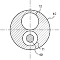
- FIG. 1 is a cross-sectional view taken along the longitudinal direction of the first balloon catheter 1 according to the embodiment of the present invention
- FIG. 2 is a cross section of II-II perpendicular to the longitudinal direction of the balloon catheter 1 shown in FIG. It is a figure.
- the balloon catheter 1 of the present invention includes a first shaft 10 having a first lumen 11 and a second lumen 12, and a second shaft 20 arranged on the distal side of the first shaft 10.
- the balloon 30 is arranged on the distal side of the second shaft 20, and the optical fiber 40 is arranged on the inner side of the balloon 30, and the optical fiber 40 is the distal end of the first lumen 11.
- the material constituting the first shaft 10 is a resin, and as shown in FIG. 2, the cross-sectional areas of the resin forming the first shaft 10 in the cross section perpendicular to the longitudinal direction are the first lumen 11 and the first.
- the cross-sectional area of 2 lumens 12 is larger than the cross-sectional area of either one. That is, of the cross-sectional area of the first lumen 11 and the cross-sectional area of the second lumen 12, the cross-sectional area of the resin forming the first shaft 10 is larger than the larger cross-sectional area. In other words, the cross-sectional area of the resin forming the first shaft 10 is larger than the cross-sectional area of either the first lumen 11 or the second lumen 12.
- the cross-sectional area of the resin forming the first shaft 10 is larger than the cross-sectional area of either the first rumen 11 and the second rumen 12 having a large cross-sectional area, and the optical fiber 40 is the first.
- the balloon is joined to the distal end 11d of the lumen 11, the proximal end 30p of the balloon 30 is joined to the second shaft 20, and the distal end 30d of the balloon 30 is joined to the optical fiber 40. Since the proximal end 30p of the 30 is connected to the first shaft 10 via the second shaft 20, and the distal end 30d of the balloon 30 is connected to the first shaft 10 via the optical fiber 40.
- the pulling force of the first shaft 10 is easily transmitted to both the proximal end 30p and the distal end 30d of the balloon 30. Therefore, it is possible to improve the removability when the balloon catheter 1 is removed from an endoscope or the like.
- the optical fiber 40 is joined to the distal end 11d of the first lumen 11, the proximal end 30p of the balloon 30 is joined to the second shaft 20, and the distal end 30d of the balloon 30 is joined to the optical fiber 40.
- the optical fiber 40 is joined to the distal end 11d of the first lumen 11 which is proximal to the proximal end 30p of the balloon 30. Therefore, in the longitudinal direction of the balloon catheter 1, the optical fiber 40 is not fixed to another object between the distal end 30d of the balloon 30 and the distal end 11d of the first lumen 11, and the balloon catheter 1 is adjusted to the bent state.
- the balloon 40 can be freely repositioned and bent.
- the optical fiber 40 can be arranged at the center of the cross section of the balloon 30 perpendicular to the longitudinal direction, which facilitates photodynamic therapy. be able to.
- the proximal end 30p of the balloon 30 is preferably joined to the distal end 20d of the second shaft 20, and the distal end 30d of the balloon 30 is joined to the distal end 40d of the optical fiber 40. preferable.
- the bonding between the optical fiber 40 and the first lumen 11, the bonding between the balloon 30 and the second shaft 20, and the bonding between the balloon 30 and the optical fiber 40 may be directly bonded to each other, or may be bonded via other members. It may have been done.
- Examples of the joining of the optical fiber 40 and the first lumen 11, the joining of the balloon 30 and the second shaft 20, and the joining of the balloon 30 and the optical fiber 40 include methods such as welding and adhesion.
- the proximal side refers to the user, that is, the operator's hand side with respect to the longitudinal direction of the first shaft 10
- the distal side refers to the direction opposite to the proximal side, that is, the treatment target side. ..
- the direction from the proximal side to the distal side of the first shaft 10 or the direction from the distal side to the proximal side is referred to as a longitudinal direction.
- the longitudinal direction can be rephrased as the perspective direction of the first shaft 10.
- the first shaft 10 extends in the longitudinal direction and has a tubular structure including a first lumen 11 and a second lumen 12.
- first lumen 11 the distal end 11d of the first lumen 11 is joined to the optical fiber 40, and the optical fiber 40 can be arranged inside the first lumen 11.
- the second lumen 12 communicates with the lumen of the balloon 30 and can serve as a path for supplying fluid to the inside of the balloon 30.
- the junction between the distal end 11d of the first lumen 11 and the optical fiber 40 does not have a gap in which the first lumen 11 and the outside of the first lumen 11 communicate with each other. That is, the optical fiber 40 is preferably joined so as to seal the distal end 11d of the first lumen 11.
- the junction between the distal end 11d of the first lumen 11 and the optical fiber 40 is supplied through the second lumen 12 because it does not have a gap in which the first lumen 11 and the outside of the first lumen 11 communicate with each other. Prevents the fluid from entering the first lumen 11.
- the balloon 30 can be expanded quickly, the time required for expansion of the balloon 30 can be shortened, and the procedure time can be shortened.
- the first shaft 10 may include at least the first lumen 11 and the second lumen 12, and may further have lumens different from those of the first lumen 11 and the second lumen 12.
- the first shaft 10 preferably has flexibility. Since the first shaft 10 has flexibility, the first shaft 10 becomes flexible and easy to bend. Therefore, the balloon catheter 1 can be easily inserted into the body.
- the material constituting the first shaft 10 is a resin, and as shown in FIG. 2, the cross-sectional areas of the resin forming the first shaft 10 in the cross section perpendicular to the longitudinal direction are the first lumen 11 and the second lumen 12.
- the cross-sectional area of is larger than the cross-sectional area of either one.
- the cross-sectional area of the second lumen 12 is larger than the cross-sectional area of the first lumen 11, the cross-sectional area of the second lumen 12 and the first shaft 10 are formed. Compare with the cross-sectional area of the resin to be used.
- first shaft 10 When the cross-sectional area of the first lumen 11 and the cross-sectional area of the second lumen 12 are the same, either the cross-sectional area of the first lumen 11 or the cross-sectional area of the second lumen 12 is used as the first shaft 10. It may be used for comparison with the cross-sectional area of the resin to be formed.
- the rigidity of the first shaft 10 can be increased by having the cross-sectional area of the resin forming the first shaft 10 larger than the cross-sectional area of either the first lumen 11 and the second lumen 12 having a large cross-sectional area. ..
- the cross-sectional area of the resin forming the first shaft 10 is 1.1 times or more the cross-sectional area of either one having a large cross-sectional area of the first lumen 11 and the second lumen 12. Is preferable, 1.2 times or more is more preferable, and 1.3 times or more is further preferable.
- the first It is possible to sufficiently increase the rigidity of 1 shaft 10.
- the cross-sectional area of the resin forming the first shaft 10 is preferably 5 times or less, preferably 4 times or less, the cross-sectional area of either one having a large cross-sectional area of the first lumen 11 and the second lumen 12. More preferably, it is more preferably 3 times or less.
- the material constituting the first shaft 10 is, for example, a polyolefin resin such as polyethylene or polypropylene, a polyamide resin such as nylon, a polyester resin such as PET, an aromatic polyether ketone resin such as PEEK, or a vinyl chloride resin. , Polyether polyamide resin, polyurethane resin, polyimide resin, synthetic resin such as fluorine resin such as PTFE, PFA, ETFE and the like. These may be used alone or in combination of two or more. Above all, the material constituting the first shaft 10 preferably contains a polyolefin-based resin, a polyamide-based resin, and a fluorine-based resin.
- the material constituting the first shaft 10 contains a polyolefin resin, a polyamide resin, and a fluorine resin, the first shaft 10 has flexibility and the surface of the first shaft 10 is slippery. Therefore, the balloon catheter 1 having good insertability can be obtained.
- the second shaft 20 has a tubular structure extending in the longitudinal direction and having a lumen.
- the second shaft 20 is arranged on the distal side of the first shaft 10. That is, the second shaft 20 is arranged on the distal side of the distal end 10d of the first shaft 10.
- An optical fiber 40 is arranged in the lumen of the second shaft 20.
- the second shaft 20 preferably has flexibility. Since the second shaft 20 has flexibility, the second shaft 20 becomes flexible, and the insertability of the balloon catheter 1 can be improved.
- the second shaft 20 may be composed of a plurality of members, but is preferably composed of one tubular member. Since the second shaft 20 is composed of one tubular member, the second shaft 20 becomes flexible. As a result, when the balloon catheter 1 is inserted into the bent internal lumen, the second shaft 20 is easily bent, and the insertability of the balloon catheter 1 can be improved.
- the material constituting the second shaft 20 is, for example, a polyolefin resin such as polyethylene or polypropylene, a polyamide resin such as nylon, a polyester resin such as PET, an aromatic polyether ketone resin such as PEEK, or a vinyl chloride resin. , Polyether polyamide resin, polyurethane resin, polyimide resin, synthetic resin such as fluorine resin such as PTFE, PFA, ETFE, metal such as stainless steel, carbon steel, nickel titanium alloy and the like. These may be used alone or in combination of two or more. Above all, it is preferable that the material constituting the second shaft 20 contains the same material as the material constituting the first shaft 10.
- the material constituting the second shaft 20 contains the same material as the material constituting the first shaft 10, the physical properties such as hardness and surface slipperiness of the first shaft 10 and the second shaft 20 are close to each other. Therefore, the balloon catheter 1 can be easily inserted into the body. Further, when the first shaft 10 and the second shaft 20 are directly joined, the joining strength between the first shaft 10 and the second shaft 20 can be increased.
- the balloon 30 is arranged on the distal side of the second shaft 20. That is, the balloon 30 is arranged distal to the distal end 20d of the second shaft 20. Further, the proximal end 30p of the balloon 30 is joined to the second shaft 20, and the distal end 30d of the balloon 30 is joined to the optical fiber 40. The proximal end 30p of the balloon 30 is preferably joined to the distal end 20d of the second shaft 20.
- the balloon 30 is configured so that fluid is supplied from the fluid feeder to the inside of the balloon 30 through the first shaft 10 and the second shaft 20.
- the balloon 30 can be expanded.
- the balloon 30 can be contracted by removing the fluid inside the balloon 30 from the balloon 30.
- the fluid supplied to the inside of the balloon 30 may be a pressure fluid pressurized by a pump or the like.
- the type of fluid supplied into the balloon 30 for example, a liquid such as physiological saline, a contrast medium, or a mixed solution thereof, or a gas such as air, nitrogen, or carbon dioxide can be used.
- the fluid supplied into the balloon 30 is preferably a gas. Since the fluid supplied into the balloon 30 is a gas, the fluid existing in the balloon 30 interferes with the emission light of the optical fiber 40 arranged inside the balloon 30 when performing photodynamic therapy. It becomes difficult.
- the balloon 30 preferably has a straight tube portion 31. Since the balloon 30 has the straight tube portion 31, the area where the balloon 30 and the luminal wall in the body are in contact with each other can be increased. Therefore, the balloon 30 can be fixed in the lumen of the body, and photodynamic therapy can be easily performed.
- the balloon 30 is located at the proximal taper portion connected to the straight tube portion 31 on the proximal side of the proximal end 31p of the straight tube portion 31 and on the distal side of the distal end 31d of the straight tube portion 31. It has a distal taper portion connected to the straight pipe portion 31, and the proximal taper portion and the distal taper portion are formed so as to decrease in diameter as the distance from the straight pipe portion 31 increases. preferable.
- the proximal side tapered portion and the distal side tapered portion formed so that the diameter of the balloon 30 decreases as the distance from the straight tube portion 31 increases, the strength of the balloon 30 can be increased, and the balloon can be increased.
- the balloon 30 can be prevented from being damaged when a force is applied to the 30. Further, since the step generated when the balloon 30 is wound around the shaft can be reduced, the balloon 30 can be easily inserted into the lumen in the body.
- the balloon 30 can be configured so that the distal taper portion swells from the proximal taper portion through the straight pipe portion 31 when a fluid is supplied.
- the inflatable portion is regarded as the balloon 30.
- the material constituting the balloon 30 is, for example, a polyolefin resin such as polyethylene, polypropylene or an ethylene-propylene copolymer, a polyester resin such as polyethylene terephthalate or a polyester elastomer, a polyurethane resin such as polyurethane or a polyurethane elastomer, or a polyphenylene sulfide type.
- a polyolefin resin such as polyethylene, polypropylene or an ethylene-propylene copolymer
- a polyester resin such as polyethylene terephthalate or a polyester elastomer
- a polyurethane resin such as polyurethane or a polyurethane elastomer
- a polyphenylene sulfide type examples thereof include polyamide resins such as resins, polyamides and polyamide elastomers, vinyl chloride resins, fluororesins, silicone resins, and natural rubbers such as latex rubber. Only one of
- the material constituting the balloon 30 is preferably a polyamide resin, a polyester resin, or a polyurethane resin.
- the material constituting the balloon 30 is a polyamide resin, a polyester resin, or a polyurethane resin, the balloon 30 can be made thinner and its flexibility can be improved.
- the optical fiber 40 extends in the longitudinal direction. Further, the optical fiber 40 is arranged inside the balloon 30 and is joined to the distal end 11d of the first lumen 11.
- the optical fiber 40 is a transmission line that transmits an optical signal to the target tissue.
- the optical fiber 40 is connected to a light source such as a semiconductor laser by a connector or the like provided at the proximal end.
- the optical fiber 40 has a core and a cladding that covers the radial outer side of the core.
- synthetic resin such as fluorine-based resin and acrylic resin
- glass such as quartz glass and fluoride glass
- the optical fiber 40 preferably has a clad non-existent portion in a part of the distal portion of the core.
- the non-existing portion of the clad refers to a portion where the clad does not exist in at least a part in the circumferential direction of the core, and serves as a light emitting area of the optical fiber 40. Since the optical fiber 40 has a non-existent portion of the clad, it is a side irradiation type and can form a balloon catheter 1 used for photodynamic therapy.
- the position where the non-existing portion of the clad is provided in the longitudinal direction is not particularly limited as long as it is a part of the distal portion of the core, but it is preferably provided in the portion including the distal end of the core. Since the non-existent portion of the clad is provided in the portion including the distal end of the core, the non-existent portion of the clad is easily formed.
- the non-existent portion of the clad can be formed by peeling the clad by, for example, etching or polishing. Further, it is more preferable to roughen the outer surface of the non-existing portion of the clad by a method such as sanding. The light diffusivity can be improved by roughening the outer surface of the non-existent portion of the clad.
- the optical fiber 40 may further have a covering material.
- the material constituting the coating material is, for example, a polyolefin resin such as polyethylene or polypropylene, a polyamide resin such as nylon, or the like.
- Polyester resin such as PET, aromatic polyetherketone resin such as PEEK, vinyl chloride resin, polyether polyamide resin, polyurethane resin, polyimide resin, fluorinated resin such as PTFE, PFA, ETFE, etc. Is preferable.
- the balloon catheter 1 Since the balloon catheter 1 has the optical fiber 40 and the optical fiber 40 is arranged inside the balloon 30, the light emitted from the balloon 40 is likely to be directed to the straight tube portion 31 of the balloon 30. Therefore, it becomes easy to irradiate the target tissue with the light used for photodynamic therapy through the optical fiber 40, and the photodynamic therapy can be efficiently performed.
- the distal end 40d of the optical fiber 40 is preferably located distal to the distal end 30d of the balloon 30. Since the distal end 40d of the optical fiber 40 is distal to the distal end 30d of the balloon 30, the rigidity of the distal end of the balloon catheter 1 is increased. Therefore, it becomes easy to insert the balloon catheter 1 into the body. Further, since the distal end 40d of the optical fiber 40 is on the distal side of the distal end 30d of the balloon 30, the optical fiber 40 is present over the entire length of the balloon 30 in the longitudinal direction. As a result, the optical fiber 40 can be present in the entire straight tube portion 31 of the balloon 30 in the longitudinal direction, which facilitates photodynamic therapy.
- the amount of light at the cutting edge of the optical fiber 40 is weakened, and the amount of light may not be sufficient for performing photodynamic therapy.
- the distal end 40d of the optical fiber 40 is located distal to the straight tube 31 of the balloon 30 or distal to the distal taper of the balloon 30. It is preferable to have.
- the distal end 40d of the optical fiber 40 is located distal to the straight tube 31 of the balloon 30 and distal to the distal taper to ensure a sufficient amount of light in photodynamic therapy. Can be done.
- a covering material is appropriately arranged on the optical fiber 40 or the like. It is possible to irradiate a desired site with light.
- the distal end 40d of the optical fiber 40 is preferably located distal to the distal taper of the balloon 30. Since the distal end 40d of the optical fiber 40 is on the distal side of the distal taper portion of the balloon 30, a sufficient amount of light in photodynamic therapy can be secured. Further, since the distal end 40d of the optical fiber 40 is on the distal side of the distal end 30d of the balloon 30, the rigidity of the distal end of the balloon catheter 1 is increased. Therefore, it becomes easy to insert the balloon catheter 1 into the body.
- the balloon catheter 1 preferably has a handle portion on the proximal side.
- the handle portion preferably has a lumen extending in the longitudinal direction that communicates with the first lumen 11.
- the lumen that the handle portion has and communicates with the first lumen 11 can be used as an insertion passage for the optical fiber 40 or the like.
- the handle portion includes a fluid injection portion and has a lumen communicating with the second lumen 12.
- the lumen that the handle portion has and communicates with the second lumen 12 can be used as a fluid supply and removal path for expanding the balloon 30.
- the proximal end 20p of the second shaft 20 is preferably joined to the distal end 10d of the first shaft 10. That is, it is preferable that the first shaft 10 and the second shaft 20 are directly joined. Since the proximal end 20p of the second shaft 20 is joined to the distal end 10d of the first shaft 10, the second shaft 20 can be easily joined to the first shaft 10. As a result, the efficiency of manufacturing the balloon catheter 1 can be improved.
- FIG. 3 is a cross-sectional view taken along the longitudinal direction of the second balloon catheter 1 according to the embodiment of the present invention
- FIG. 4 is an IV-IV perpendicular to the longitudinal direction of the balloon catheter 1 shown in FIG. It is a cross-sectional view.
- the first shaft 10 of the balloon catheter 1 includes an inner cylinder portion 50 having a first lumen 11 and a second lumen portion 12, and is provided on the outer surface of the inner cylinder portion 50. At least a part is fixed to the inner surface of the first shaft 10.
- the first shaft 10 includes an inner cylinder portion 50 having a first lumen 11 and a second lumen 12, and at least a part of the outer surface of the inner cylinder portion 50 is fixed to the inner surface of the first shaft 10, and an optical fiber is used.
- 40 is joined to the distal end 50d of the inner cylinder 50, the proximal end 30p of the balloon 30 is joined to the second shaft 20, and the distal end 30d of the balloon 30 is joined to the optical fiber 40.
- the proximal end 30p of the balloon 30 is connected to the first shaft 10 via the second shaft 20, and the distal end 30d of the balloon 30 is connected to the first shaft 10 via the optical fiber 40. It becomes.
- the force that pulls the first shaft 10 toward the hand side is easily transmitted to both the distal end 30d and the proximal end 30p of the balloon 30, and the balloon catheter 1 is removed.
- the sex can be improved.
- the proximal end 30p of the balloon 30 is preferably joined to the distal end 20d of the second shaft 20, and the distal end 30d of the balloon 30 is joined to the distal end 40d of the optical fiber 40. Is preferable.
- the optical fiber 40 is joined to the distal end 50d of the inner cylinder portion 50, the proximal end 30p of the balloon 30 is joined to the second shaft 20, and the distal end 30d of the balloon 30 is joined to the optical fiber 40. Therefore, in the longitudinal direction of the balloon catheter 1, the optical fiber 40 is not fixed to another object between the distal end 30d of the balloon 30 and the distal end 11d of the first lumen 11, and the optical fiber 40 is a balloon catheter. It is possible to freely change the position or bend according to the bending state of 1. Therefore, when performing photodynamic therapy for irradiating the target tissue with light, the optical fiber 40 can be arranged at the center of the cross section of the balloon 30 perpendicular to the longitudinal direction, which facilitates photodynamic therapy.
- the inner cylinder portion 50 extends in the longitudinal direction.
- An optical fiber 40 is inserted into the lumen of the inner cylinder portion 50.
- Examples of the method of fixing at least a part of the outer surface of the inner cylinder portion 50 to the inner surface of the first shaft 10 include welding, adhesion, fixing via other parts, and the like.
- the length L1 of the second shaft 20 in the longitudinal direction is preferably 10 times or more the minimum outer diameter of the second shaft 20.
- the length L1 of the second shaft 20 in the longitudinal direction indicates the distance between the distal end 20d of the second shaft 20 and the proximal end 20p of the second shaft 20 in the longitudinal direction. Since the length L1 of the second shaft 20 is 10 times or more the minimum outer diameter of the second shaft 20, the length L1 of the second shaft 20 can be made sufficient and is joined to the optical fiber 40. The distance from the distal end 30d of the balloon 30 to the distal end 11d of the first lumen 11 joined to the optical fiber 40 can be increased.
- the distance between the two points where the optical fiber 40 is joined to another object can be separated, and the optical fiber 40 can freely adjust to the bent state of the balloon catheter 1 in the portion where the optical fiber 40 is not bonded to another object. It is possible to change the position and bend. As a result, the optical fiber 40 is located at the center of the cross section of the balloon 30 perpendicular to the longitudinal direction, and photodynamic therapy can be efficiently performed.
- the length L1 of the second shaft 20 in the longitudinal direction is preferably 10 times or more the minimum outer diameter of the second shaft 20, and more preferably 11 times or more the minimum outer diameter of the second shaft 20. It is more preferable that the diameter is 12 times or more the minimum outer diameter of the second shaft 20.
- the optical fiber 40 is formed from the distal end 30d of the balloon 30 joined to the optical fiber 40. The distance to the distal end 11d of the first lumen 11 joined to can be sufficiently separated.
- the upper limit of the ratio between the length L1 of the second shaft 20 and the minimum outer diameter of the second shaft 20 can be, for example, 600 times or less, 400 times or less, and 200 times or less.
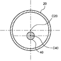
- the position of the central axis C20 of the outer shape of the second shaft 20 and the position of the central axis C40 of the outer shape of the optical fiber 40 is preferably different. Since the position of the central axis C20 of the outer shape of the second shaft 20 and the position of the central axis C40 of the outer shape of the optical fiber 40 are different, the optical fiber 40 is free in the respective lumens of the second shaft 20 and the balloon 30. It becomes easier to change the position and bend.
- the optical fiber 40 easily moves according to the bent state of the balloon catheter 1, and the optical fiber 40 is located at the center of the cross section of the balloon 30 perpendicular to the longitudinal direction. It will be easier. As a result, photodynamic therapy becomes easier to perform.
- the cross-sectional area of the gap portion formed by the inner surface of the second shaft 20 and the outer surface of the optical fiber 40 is the cross section of the second shaft 20. It is preferably 40% or more of the cross-sectional area of the lumen.
- the cross-sectional area of the gap formed between the inner surface of the second shaft 20 and the outer surface of the optical fiber 40 is 40% or more of the cross-sectional area of the lumen of the second shaft 20, the inside of the second shaft 20
- the optical fiber 40 can move freely. Therefore, even when the second shaft 20 is bent, the optical fiber 40 is likely to be located at the center of the cross section of the balloon 30 perpendicular to the longitudinal direction, which facilitates photodynamic therapy.
- the cross-sectional area of the gap formed by the inner surface of the second shaft 20 and the outer surface of the optical fiber 40 is 40, which is the cross-sectional area of the lumen of the second shaft 20. % Or more, more preferably 45% or more, and even more preferably 50% or more.
- the upper limit of the ratio between the cross-sectional area of the gap formed by the inner surface of the second shaft 20 and the outer surface of the optical fiber 40 and the cross-sectional area of the lumen of the second shaft 20 is, for example, 99% or less. , 97% or less, 95% or less.
- FIG. 5 is a cross-sectional view perpendicular to the longitudinal direction of the second shaft 20 of the balloon catheter 1 according to another embodiment of the present invention.
- the inner surface of the second shaft 20 has a protrusion 70 that comes into contact with the outer surface of the optical fiber 40.
- the protrusion 70 can determine the position of the optical fiber 40 in the second shaft 20.
- the position of the optical fiber 40 can be regulated so as not to deviate significantly from the central axis of the balloon 30.
- the protrusion 70 is not joined to the optical fiber 40.
- the protrusion 70 is preferably arranged on the inner surface of the distal end of the second shaft 20.
- a protrusion 70 that contacts the outer surface of the optical fiber 40 is placed on the inner surface of the distal end of the second shaft 20 so that the optical fiber 40 is located at the center of the second shaft 20 in a cross section perpendicular to the longitudinal direction.
- the position of the optical fiber 40 at the distal end of the second shaft 20 is likely to be located at the center of the second shaft 20.
- the position of the optical fiber 40 is easily arranged in the center of the balloon 30 even in the lumen of the balloon 30 which is arranged on the distal side of the second shaft 20 and is joined to the second shaft 20, and the light beam.
- the balloon catheter 1 can be used for easy dynamic therapy.
- the number of protrusions 70 arranged on the inner surface of the second shaft 20 is preferably a plurality. Since the number of protrusions 70 is plural, the position of the optical fiber 40 in the second shaft 20 can be easily regulated by the protrusions 70.
- the tip 60 is arranged on the distal side of the optical fiber 40, and the distal end 60d of the tip 60 is distal to the distal end 30d of the balloon 30. Is preferable. Since the distal end 60d of the tip tip 60 is distal to the distal end 30d of the balloon 30, the rigidity of the distal end of the balloon catheter 1 is increased. As a result, the insertability of the balloon catheter 1 can be improved.
- the color of the tip 60 is preferably different from the color of the optical fiber 40.
- the difference between the color of the tip chip 60 and the color of the optical fiber 40 means that at least one of the hue, lightness, and saturation defined in JIS Z8721 is different. Since the color of the tip tip 60 is different from the color of the optical fiber 40, the tip tip 60 is easily visible under an endoscope. As a result, the positions of the tip tip 60 and the balloon 30 can be easily confirmed in the lumen of the body.
- the balloon catheter of the present invention has a first shaft having a first lumen and a second lumen, a second shaft arranged on the distal side of the first shaft, and a distal side of the second shaft. It has a balloon arranged in the balloon and an optical fiber arranged inside the balloon, and the material constituting the first shaft is a resin, which is the first in a cross section perpendicular to the longitudinal direction.
- the cross-sectional area of the resin forming the shaft is larger than the cross-sectional area of either the first rumen or the second rumen, which has a larger cross-sectional area, and the optical fiber is joined to the distal end of the first rumen of the balloon.
- the proximal end is joined to the second shaft and the distal end of the balloon is joined to the optical fiber.
- the cross-sectional area of the resin forming the first shaft in the longitudinally perpendicular section is larger than the cross-sectional area of either the first rumen or the second lumen, which has a larger cross-sectional area, and the optical fiber is located at the distal end of the first rumen. It is joined, the proximal end of the balloon is joined to the second shaft, and the distal end of the balloon is joined to the optical fiber so that the force applied to the balloon catheter is far from the proximal end of the balloon. Easy to convey to both ends. Therefore, it is possible to improve the removability of the balloon catheter from an endoscope or the like.
- the optical fiber is joined to the distal end of the first lumen, which is proximal to the proximal end of the balloon, rather than the proximal end of the balloon, the first lumen from the distal end of the balloon in the longitudinal direction.
- the optical fiber is not fixed to anything else up to the distal end of the fracture and can move freely.
- An optical fiber can be arranged in the part, which makes it easier to perform photodynamic therapy.
- the second balloon catheter of the present invention includes an inner cylinder portion having a first lumen, a first shaft including a second lumen, and a second shaft arranged on the distal side of the first shaft.
- a balloon arranged on the distal side of the second shaft and an optical fiber arranged on the inner side of the balloon, and at least a part of the outer surface of the inner cylinder portion of the first shaft Fixed to the inner surface, the optical fiber is joined to the distal end of the inner cylinder, the proximal end of the balloon is joined to the second shaft, and the distal end of the balloon is joined to the optical fiber. Has been done.
- the first shaft has an inner cylinder portion having a first lumen and a second lumen, and at least a part of the outer surface of the inner cylinder portion is fixed to the inner surface of the first shaft, and the optical fiber is far from the inner cylinder portion. It is joined to the position end, the proximal end of the balloon is joined to the second shaft, and the distal end of the balloon is joined to the optical fiber, so that when removing the balloon catheter from an endoscope or the like.
- the pulling force of the balloon catheter is easily transmitted to the proximal and distal ends of the balloon, making it easier to remove the balloon catheter from an endoscope or the like.
- the optical fiber since the optical fiber is joined to the distal end of the first lumen, the optical fiber can move freely from the distal end of the balloon in the longitudinal direction to the distal end of the first lumen. Therefore, even when the shaft of the balloon catheter is bent or the balloon is compressed, the optical fiber can be arranged at the center of the cross section of the balloon perpendicular to the longitudinal direction.
- Balloon catheter 10 1st shaft 10d: Distal end of 1st shaft 11: 1st lumen 11d: Distal end of 1st lumen 11p: Proximal end of 1st lumen 12: 2nd lumen 20: 2nd Shaft 20d: Distal end of second shaft 20p: Proximal end of second shaft 30: Balloon 30d: Distal end of balloon 30p: Proximal end of balloon 31: Straight tube 31d: Distal end of straight tube 31p: Proximal end of straight tube 40: Optical fiber 40d: Distal end of optical fiber 50: Inner cylinder 50d: Distal end of inner cylinder 60: Tip tip 60d: Distal end of tip tip 70: Protrusion L1: Length of 2nd shaft C20: Central axis of outer shape of 2nd shaft C40: Central axis of outer shape of optical fiber
Abstract
A balloon catheter (1) is characterized by including: a first shaft (10) provided with a first lumen (11) and a second lumen (12); a second shaft (20) disposed at the distal end side of the first shaft (10); a balloon (30) disposed at the distal end side of the second shaft (20); and an optical fiber (40) that is disposed within the balloon (30). The balloon catheter is further characterized in that: the material constituting the first shaft (10) is a resin, and in a cross-section perpendicular to the longitudinal direction, the cross-sectional area of the resin forming the first shaft (10) is larger than the cross-sectional area of the first lumen (11) or the second lumen (12), whichever has the larger cross-sectional area; the optical fiber (40) is joined to the distal end (11d) of the first lumen (11); the proximal end (30p) of the balloon (30) is joined to the second shaft (20); and the distal end (30d) of the balloon (30) is joined to the optical fiber (40).
Description
本発明は、血管や消化管等の体内管腔において、がん細胞等の組織に光を照射する際等に用いるバルーンカテーテルに関するものである。
The present invention relates to a balloon catheter used when irradiating tissues such as cancer cells with light in internal lumens such as blood vessels and gastrointestinal tracts.
光線力学的療法(Photodynamic Therapy:PDT)では、光増感剤を静脈注射や腹腔内投与で体内に投与し、がん細胞等の対象組織に光増感剤を集積させ、特定の波長の光を対象組織に照射することにより光増感剤を励起させる。励起された光増感剤が基底状態に戻るときにエネルギー転換が生じ、活性酸素種を発生させる。この活性酸素種が対象組織を攻撃することにより、対象組織を除去することができる。また、レーザー光を用いたアブレーション(組織焼灼)では、対象組織にレーザー光を照射して焼灼することが行われる。
In photodynamic therapy (PDT), a photosensitizer is administered into the body by intravenous injection or intraperitoneal administration, and the photosensitizer is accumulated in the target tissue such as cancer cells to accumulate light of a specific wavelength. The photosensitizer is excited by irradiating the target tissue with. When the excited photosensitizer returns to the ground state, energy conversion occurs, generating reactive oxygen species. By attacking the target tissue with this reactive oxygen species, the target tissue can be removed. Further, in ablation (tissue cauterization) using laser light, the target tissue is irradiated with laser light and cauterized.
光照射医療装置は、PDTやレーザー光を用いたアブレーションにおいて、血管や消化管等の体内管腔にてがん細胞等の対象組織である処置部に対して特定の波長の光を照射するために用いられる。光照射医療装置では、対象組織に光を照射するためにカテーテルの管内に光ファイバーが配置される。
In ablation using PDT or laser light, a light irradiation medical device irradiates a treatment part, which is a target tissue such as a cancer cell, with light of a specific wavelength in an internal lumen such as a blood vessel or a gastrointestinal tract. Used for. In a light irradiation medical device, an optical fiber is arranged in a catheter tube to irradiate a target tissue with light.
光照射医療装置は、単独で処置部まで送達されるものもあるが、一般的には、送達用のカテーテルや内視鏡と共に用いられる。内視鏡を用いた治療において光照射医療装置は、内視鏡の鉗子口を通じて内視鏡の鉗子口の遠位側から体内に配置され、処置部まで送達される。
Although some light irradiation medical devices are delivered to the treatment site alone, they are generally used together with a delivery catheter or an endoscope. In endoscopic treatment, the light irradiation medical device is placed in the body from the distal side of the forceps opening of the endoscope through the forceps opening of the endoscope and delivered to the treatment site.
例えば、特許文献1には、末梢端部及び手元端部を有する管状基体と、その末梢端部に配置されて管状基体の末梢端部のある部分を囲撓しているバルーンメンバとでなるバルーンカテーテルであり、光導装置が手元端部から末梢端部に延在しており、この光導装置はその末梢端部に近いところにバルーンメンバ内に配された発光端部を管状基体に固定した状態で具備しており、光導装置を有するバルーンカテーテルにおいて、光導装置は管状基体の管路内に延在しており、また、管状基体の端部外壁はバルーンメンバ内に延出し、かつ管路を画成していて、少なくとも部分的に予め取り除いてあることにより、光導装置の発光端部をバルーンメンバ内に露呈してあることが記載されており、発光端部に光ファイバーを用いることが記載されている。
For example, Patent Document 1 describes a balloon composed of a tubular substrate having a peripheral end and a hand end, and a balloon member arranged at the peripheral end and surrounding a portion of the tubular substrate with the peripheral end. It is a catheter, and the optical device extends from the hand end to the peripheral end, and this optical device has a light emitting end arranged in a balloon member fixed to a tubular substrate near the peripheral end. In a balloon catheter having an optical device, the optical device extends into the conduit of the tubular substrate, and the outer wall of the end of the tubular substrate extends into the balloon member and extends the conduit. It is described that the light emitting end portion of the optical device is exposed in the balloon member by being imaged and at least partially removed in advance, and it is described that an optical fiber is used for the light emitting end portion. ing.
特許文献2には、シャフトは、内側チューブと外側チューブとを有し、外側チューブの先端にバルーンを配置し、内側チューブを外側チューブの後方からバルーンの内部を経てバルーンの先端に至るまで配置し、少なくとも内側チューブの内部にレーザーファイバーを挿入可能なルーメンを有し、外側チューブの後端にレーザーファイバーの挿入口を形成し、バルーンの外周に光感受性物質を固定し、位置決め用のマーカーをバルーン中央の内側チューブの外周に一箇所設けるか、または、バルーン中央から等間隔にバルーン両側の内側チューブの外周に二箇所設け、レーザーファイバーのストッパーをレーザーファイバーの先端がバルーンの中央で止まるように、バルーン中央の内側チューブ内に設けたことを特徴とするレーザーファイバーの誘導カテーテルが記載されている。
In Patent Document 2, the shaft has an inner tube and an outer tube, a balloon is arranged at the tip of the outer tube, and the inner tube is arranged from the rear of the outer tube through the inside of the balloon to the tip of the balloon. , At least has a lumen into which the laser fiber can be inserted inside the inner tube, forms an insertion port for the laser fiber at the rear end of the outer tube, fixes a photosensitizer on the outer circumference of the balloon, and holds a positioning marker on the balloon. One place on the outer circumference of the inner tube in the center, or two places on the outer circumference of the inner tube on both sides of the balloon at equal intervals from the center of the balloon, so that the tip of the laser fiber stops at the center of the balloon. Described is a laser fiber induction catheter characterized in that it is provided within an inner tube at the center of the balloon.
しかし、特許文献1および2のバルーンカテーテルでは、バルーンカテーテルを内視鏡等から抜去するためにバルーンカテーテルを手元側へ引いた際に、バルーンカテーテルを手元側へ引く力がバルーンの遠位端部まで伝わりにくい。そのため、内視鏡からバルーンカテーテルを抜去することが困難であるという問題があった。
However, in the balloon catheters of Patent Documents 1 and 2, when the balloon catheter is pulled toward the hand side in order to remove the balloon catheter from the endoscope or the like, the force of pulling the balloon catheter toward the hand side is the distal end of the balloon. It is difficult to convey to. Therefore, there is a problem that it is difficult to remove the balloon catheter from the endoscope.
さらに、特許文献1および2のバルーンカテーテルでは、バルーンカテーテルを屈曲した体内管腔に配置した際に、光ファイバーも屈曲する。また、体内管腔に特許文献1および2のバルーンカテーテルを配置した際にバルーンが体内管腔に拘束され、バルーンが圧縮されて軸方向の長さが短くなる場合にも光ファイバーは屈曲する。そのため、バルーンの内部における光ファイバーの位置が長手方向に垂直なバルーンの断面の中心部から外れ、対象組織に十分な光を照射することができずに光線力学的療法が十分に行えないことや、対象組織に想定よりも強い光を照射してしまい体内組織が穿孔してしまうことがあるという問題もあった。
Furthermore, in the balloon catheters of Patent Documents 1 and 2, the optical fiber also bends when the balloon catheter is placed in the bent internal lumen. Further, when the balloon catheters of Patent Documents 1 and 2 are arranged in the lumen of the body, the balloon is restrained in the lumen of the body, and the optical fiber is bent even when the balloon is compressed and the length in the axial direction is shortened. Therefore, the position of the optical fiber inside the balloon deviates from the center of the cross section of the balloon perpendicular to the longitudinal direction, and the target tissue cannot be sufficiently irradiated with light, so that photodynamic therapy cannot be sufficiently performed. There is also a problem that the target tissue is irradiated with light stronger than expected and the internal tissue may be perforated.
本発明は、前記の事情に鑑みてなされたものであり、その目的は、内視鏡等からの抜去性がよく、シャフトが屈曲した状態やバルーンが圧縮された状態であっても光ファイバーの位置が長手方向に垂直なバルーンの断面の中心部となるバルーンカテーテルを提供することにある。
The present invention has been made in view of the above circumstances, and an object of the present invention is that the position of the optical fiber is easily removed from an endoscope or the like, and the position of the optical fiber is obtained even when the shaft is bent or the balloon is compressed. Is to provide a balloon catheter that is central to the cross section of a balloon that is perpendicular to the longitudinal direction.
前記課題を解決することができた第1のバルーンカテーテルは、第1ルーメンおよび第2ルーメンを備える第1シャフトと、第1シャフトの遠位側に配置されている第2シャフトと、第2シャフトの遠位側に配置されているバルーンと、バルーンの内方に配置されている光ファイバーと、を有しており、第1シャフトを構成する材料は、樹脂であって、長手方向に垂直な断面において、第1シャフトを形成する樹脂の断面積は、第1ルーメンと第2ルーメンの断面積が大きいいずれか一方の断面積よりも大きく、光ファイバーは、第1ルーメンの遠位端に接合されており、バルーンの近位端は、第2シャフトに接合されており、バルーンの遠位端は、光ファイバーに接合されていることを特徴とするものである。
The first balloon catheter that was able to solve the above problems includes a first shaft having a first lumen and a second lumen, a second shaft arranged on the distal side of the first shaft, and a second shaft. It has a balloon arranged on the distal side of the balloon and an optical fiber arranged on the inside of the balloon, and the material constituting the first shaft is resin and has a cross section perpendicular to the longitudinal direction. In, the cross-sectional area of the resin forming the first shaft is larger than the cross-sectional area of either the first rumen and the second rumen having a larger cross-sectional area, and the optical fiber is joined to the distal end of the first rumen. The proximal end of the balloon is joined to a second shaft and the distal end of the balloon is joined to an optical fiber.
前記課題を解決することができた第2のバルーンカテーテルは、第1ルーメンを有する内筒部と、第2ルーメンと、を備える第1シャフトと、第1シャフトの遠位側に配置されている第2シャフトと、第2シャフトの遠位側に配置されているバルーンと、バルーンの内方に配置されている光ファイバーと、を有しており、内筒部の外表面の少なくとも一部は、第1シャフトの内表面に固定されており、光ファイバーは、内筒部の遠位端に接合されており、バルーンの近位端は、第2シャフトに接合されており、バルーンの遠位端は、光ファイバーに接合されていることを特徴とするものである。
The second balloon catheter, which has been able to solve the above-mentioned problems, is arranged on the inner cylinder portion having the first lumen, the first shaft including the second lumen, and the distal side of the first shaft. It has a second shaft, a balloon located on the distal side of the second shaft, and an optical fiber arranged inside the balloon, and at least a part of the outer surface of the inner cylinder portion. Fixed to the inner surface of the first shaft, the optical fiber is joined to the distal end of the inner cylinder, the proximal end of the balloon is joined to the second shaft, and the distal end of the balloon is , It is characterized in that it is joined to an optical fiber.
本発明のバルーンカテーテルにおいて、長手方向における第2シャフトの長さは、第2シャフトの最小外径の10倍以上であることが好ましい。
In the balloon catheter of the present invention, the length of the second shaft in the longitudinal direction is preferably 10 times or more the minimum outer diameter of the second shaft.
本発明のバルーンカテーテルは、第2シャフトの近位端での長手方向に垂直な断面において、第2シャフトの外形の中心軸の位置と、光ファイバーの外形の中心軸の位置とが異なっていることが好ましい。
In the balloon catheter of the present invention, the position of the central axis of the outer shape of the second shaft and the position of the central axis of the outer shape of the optical fiber are different in the cross section perpendicular to the longitudinal direction at the proximal end of the second shaft. Is preferable.
本発明のバルーンカテーテルは、第2シャフトの長手方向に垂直な断面において、第2シャフトの内表面と光ファイバーの外表面とで形成される間隙部分の面積は、第2シャフトの内腔の面積の40%以上であることが好ましい。
In the balloon catheter of the present invention, in a cross section perpendicular to the longitudinal direction of the second shaft, the area of the gap formed by the inner surface of the second shaft and the outer surface of the optical fiber is the area of the lumen of the second shaft. It is preferably 40% or more.
本発明のバルーンカテーテルにおいて、第2シャフトの内表面に、光ファイバーの外表面と接触する突起を有していることが好ましい。
In the balloon catheter of the present invention, it is preferable that the inner surface of the second shaft has a protrusion that contacts the outer surface of the optical fiber.
本発明のバルーンカテーテルにおいて、光ファイバーの遠位側に先端チップが配置されており、先端チップの遠位端は、バルーンの遠位端よりも遠位側にあることが好ましい。
In the balloon catheter of the present invention, it is preferable that the tip tip is arranged on the distal side of the optical fiber, and the distal end of the tip tip is on the distal side of the distal end of the balloon.
本発明の第1のバルーンカテーテルによれば、長手方向に垂直な断面において第1シャフトを形成する樹脂の断面積は第1ルーメンと第2ルーメンの断面積が大きいいずれか一方の断面積よりも大きく、光ファイバーは第1ルーメンの遠位端に接合されており、バルーンの近位端は第2シャフトに接合されており、バルーンの遠位端は光ファイバーに接合されていることにより、バルーンカテーテルに加えられた力がバルーンの近位端と遠位端の両方に伝わりやすい。そのため、内視鏡等からのバルーンカテーテルの抜去性を向上させることができる。また、光ファイバーがバルーンの近位端ではなく、バルーンの近位端よりも近位側にある第1ルーメンの遠位端に接合されるため、長手方向において、バルーンの遠位端から第1ルーメンの遠位端までの間は光ファイバーが他物に固定されておらず、自由に動くことが可能である。その結果、バルーンカテーテルのシャフトが屈曲した状態やバルーンが圧縮された状態であっても、長手方向に垂直なバルーンの断面の中心部に光ファイバーを配置することができる。
According to the first balloon catheter of the present invention, the cross-sectional area of the resin forming the first shaft in the cross section perpendicular to the longitudinal direction is larger than the cross-sectional area of either one having a larger cross-sectional area of the first lumen and the second lumen. Larger, the optical fiber is attached to the distal end of the first lumen, the proximal end of the balloon is attached to the second shaft, and the distal end of the balloon is attached to the optical fiber to the balloon catheter. The applied force is likely to be transmitted to both the proximal and distal ends of the balloon. Therefore, it is possible to improve the removability of the balloon catheter from an endoscope or the like. Also, since the optical fiber is joined to the distal end of the first lumen, which is proximal to the proximal end of the balloon, rather than the proximal end of the balloon, the first lumen from the distal end of the balloon in the longitudinal direction. The optical fiber is not fixed to anything else up to the distal end of the fracture and can move freely. As a result, the optical fiber can be arranged at the center of the cross section of the balloon perpendicular to the longitudinal direction even when the shaft of the balloon catheter is bent or the balloon is compressed.
本発明の第2のバルーンカテーテルによれば、第1シャフトが第1ルーメンを有する内筒部と第2ルーメンとを備え、内筒部の外表面の少なくとも一部は第1シャフトの内表面に固定されており、光ファイバーは内筒部の遠位端に接合されており、バルーンの近位端は第2シャフトに接合されており、バルーンの遠位端は光ファイバーに接合されていることにより、内視鏡等からバルーンカテーテルを抜去する際にバルーンカテーテルを引く力がバルーンの近位端および遠位端に伝わりやすく、バルーンカテーテルを内視鏡等から抜去しやすくなる。また、光ファイバーが内筒部の遠位端に接合されることより、長手方向におけるバルーンの遠位端から第1ルーメンの遠位端までの間は光ファイバーが自由に動くことができる。そのため、バルーンカテーテルのシャフトが屈曲した状態やバルーンが圧縮された状態であっても、長手方向に垂直なバルーンの断面の中心部に光ファイバーを配置することが可能となる。
According to the second balloon catheter of the present invention, the first shaft includes an inner cylinder portion having a first lumen and a second lumen, and at least a part of the outer surface of the inner cylinder portion is on the inner surface of the first shaft. It is fixed, the optical fiber is joined to the distal end of the inner cylinder, the proximal end of the balloon is joined to the second shaft, and the distal end of the balloon is joined to the optical fiber. When the balloon catheter is removed from the endoscope or the like, the force for pulling the balloon catheter is easily transmitted to the proximal end and the distal end of the balloon, and the balloon catheter can be easily removed from the endoscope or the like. Further, since the optical fiber is joined to the distal end of the inner cylinder portion, the optical fiber can move freely from the distal end of the balloon in the longitudinal direction to the distal end of the first lumen. Therefore, even when the shaft of the balloon catheter is bent or the balloon is compressed, the optical fiber can be arranged at the center of the cross section of the balloon perpendicular to the longitudinal direction.
以下、下記実施の形態に基づき本発明をより具体的に説明するが、本発明はもとより下記実施の形態によって制限を受けるものではなく、前・後記の趣旨に適合し得る範囲で適当に変更を加えて実施することも勿論可能であり、それらはいずれも本発明の技術的範囲に包含される。なお、各図面において、便宜上、ハッチングや部材符号等を省略する場合もあるが、かかる場合、明細書や他の図面を参照するものとする。また、図面における種々部材の寸法は、本発明の特徴の理解に資することを優先しているため、実際の寸法とは異なる場合がある。
Hereinafter, the present invention will be described in more detail based on the following embodiments. In addition, it is of course possible to carry out, and all of them are included in the technical scope of the present invention. In each drawing, hatching, member reference numerals, and the like may be omitted for convenience, but in such cases, the specification and other drawings shall be referred to. In addition, the dimensions of various members in the drawings may differ from the actual dimensions because priority is given to contributing to the understanding of the features of the present invention.
まず、本発明の第1のバルーンカテーテルについて説明する。
First, the first balloon catheter of the present invention will be described.
図1は、本発明の一実施の形態における第1のバルーンカテーテル1の長手方向に沿った断面図であり、図2は図1に示したバルーンカテーテル1の長手方向に垂直なII-II断面図である。図1に示すように、本発明のバルーンカテーテル1は、第1ルーメン11および第2ルーメン12を備える第1シャフト10と、第1シャフト10の遠位側に配置されている第2シャフト20と、第2シャフト20の遠位側に配置されているバルーン30と、バルーン30の内方に配置されている光ファイバー40と、を有しており、光ファイバー40は、第1ルーメン11の遠位端11dに接合されており、バルーン30の近位端30pは、第2シャフト20に接合されており、バルーン30の遠位端30dは、光ファイバー40に接合されている。また、第1シャフト10を構成する材料は樹脂であって、図2に示すように、長手方向に垂直な断面において、第1シャフト10を形成する樹脂の断面積は、第1ルーメン11と第2ルーメン12の断面積が大きいいずれか一方の断面積よりも大きい。つまり、第1ルーメン11の断面積と第2ルーメン12の断面積のうち、大きい方の断面積よりも第1シャフト10を形成する樹脂の断面積が大きい。換言すると、第1シャフト10を形成する樹脂の断面積は、第1ルーメン11と第2ルーメン12のいずれの断面積よりも大きい。
FIG. 1 is a cross-sectional view taken along the longitudinal direction of the first balloon catheter 1 according to the embodiment of the present invention, and FIG. 2 is a cross section of II-II perpendicular to the longitudinal direction of the balloon catheter 1 shown in FIG. It is a figure. As shown in FIG. 1, the balloon catheter 1 of the present invention includes a first shaft 10 having a first lumen 11 and a second lumen 12, and a second shaft 20 arranged on the distal side of the first shaft 10. The balloon 30 is arranged on the distal side of the second shaft 20, and the optical fiber 40 is arranged on the inner side of the balloon 30, and the optical fiber 40 is the distal end of the first lumen 11. It is joined to 11d, the proximal end 30p of the balloon 30 is joined to the second shaft 20, and the distal end 30d of the balloon 30 is joined to the optical fiber 40. Further, the material constituting the first shaft 10 is a resin, and as shown in FIG. 2, the cross-sectional areas of the resin forming the first shaft 10 in the cross section perpendicular to the longitudinal direction are the first lumen 11 and the first. The cross-sectional area of 2 lumens 12 is larger than the cross-sectional area of either one. That is, of the cross-sectional area of the first lumen 11 and the cross-sectional area of the second lumen 12, the cross-sectional area of the resin forming the first shaft 10 is larger than the larger cross-sectional area. In other words, the cross-sectional area of the resin forming the first shaft 10 is larger than the cross-sectional area of either the first lumen 11 or the second lumen 12.
長手方向に垂直な断面において、第1シャフト10を形成する樹脂の断面積は、第1ルーメン11と第2ルーメン12の断面積が大きいいずれか一方の断面積よりも大きく、光ファイバー40が第1ルーメン11の遠位端11dに接合されており、バルーン30の近位端30pが第2シャフト20に接合されており、バルーン30の遠位端30dが光ファイバー40に接合されていることにより、バルーン30の近位端30pが第2シャフト20を介して第1シャフト10に接続されるとともに、バルーン30の遠位端30dが光ファイバー40を介して第1シャフト10に接続される構造であるため、第1シャフト10を引く力がバルーン30の近位端30pと遠位端30dの両方に伝わりやすくなる。そのため、バルーンカテーテル1を内視鏡等から抜去する際の抜去性を向上させることが可能となる。
In the cross section perpendicular to the longitudinal direction, the cross-sectional area of the resin forming the first shaft 10 is larger than the cross-sectional area of either the first rumen 11 and the second rumen 12 having a large cross-sectional area, and the optical fiber 40 is the first. The balloon is joined to the distal end 11d of the lumen 11, the proximal end 30p of the balloon 30 is joined to the second shaft 20, and the distal end 30d of the balloon 30 is joined to the optical fiber 40. Since the proximal end 30p of the 30 is connected to the first shaft 10 via the second shaft 20, and the distal end 30d of the balloon 30 is connected to the first shaft 10 via the optical fiber 40. The pulling force of the first shaft 10 is easily transmitted to both the proximal end 30p and the distal end 30d of the balloon 30. Therefore, it is possible to improve the removability when the balloon catheter 1 is removed from an endoscope or the like.
光ファイバー40が第1ルーメン11の遠位端11dに接合されており、バルーン30の近位端30pが第2シャフト20に接合されており、バルーン30の遠位端30dが光ファイバー40に接合されていることにより、光ファイバー40がバルーン30の近位端30pよりも近位側にある第1ルーメン11の遠位端11dに接合されることとなる。そのため、バルーンカテーテル1の長手方向において、バルーン30の遠位端30dから第1ルーメン11の遠位端11dまでの間は光ファイバー40が他物に固定されず、バルーンカテーテル1の屈曲状態に合わせて光ファイバー40が自由に位置を変えたり曲がったりすることが可能となる。その結果、対象組織に光を照射して光線力学的療法を行う際に、光ファイバー40を長手方向に垂直なバルーン30の断面の中心部に配置することができ、光線力学的療法を行いやすくすることができる。
The optical fiber 40 is joined to the distal end 11d of the first lumen 11, the proximal end 30p of the balloon 30 is joined to the second shaft 20, and the distal end 30d of the balloon 30 is joined to the optical fiber 40. As a result, the optical fiber 40 is joined to the distal end 11d of the first lumen 11 which is proximal to the proximal end 30p of the balloon 30. Therefore, in the longitudinal direction of the balloon catheter 1, the optical fiber 40 is not fixed to another object between the distal end 30d of the balloon 30 and the distal end 11d of the first lumen 11, and the balloon catheter 1 is adjusted to the bent state. The balloon 40 can be freely repositioned and bent. As a result, when the target tissue is irradiated with light to perform photodynamic therapy, the optical fiber 40 can be arranged at the center of the cross section of the balloon 30 perpendicular to the longitudinal direction, which facilitates photodynamic therapy. be able to.
バルーン30の近位端30pは、第2シャフト20の遠位端20dに接合されていることが好ましく、バルーン30の遠位端30dは、光ファイバー40の遠位端40dに接合されていることが好ましい。
The proximal end 30p of the balloon 30 is preferably joined to the distal end 20d of the second shaft 20, and the distal end 30d of the balloon 30 is joined to the distal end 40d of the optical fiber 40. preferable.
光ファイバー40と第1ルーメン11との接合、バルーン30と第2シャフト20との接合、およびバルーン30と光ファイバー40との接合は、それぞれが互いに直接接合されていてもよく、他部材を介して接合されていてもよい。光ファイバー40と第1ルーメン11との接合、バルーン30と第2シャフト20との接合、およびバルーン30と光ファイバー40との接合は、例えば、溶着、接着等の方法が挙げられる。
The bonding between the optical fiber 40 and the first lumen 11, the bonding between the balloon 30 and the second shaft 20, and the bonding between the balloon 30 and the optical fiber 40 may be directly bonded to each other, or may be bonded via other members. It may have been done. Examples of the joining of the optical fiber 40 and the first lumen 11, the joining of the balloon 30 and the second shaft 20, and the joining of the balloon 30 and the optical fiber 40 include methods such as welding and adhesion.
本発明において、近位側とは、第1シャフト10の長手方向に対して使用者、つまり術者の手元側を指し、遠位側とは近位側の反対方向、すなわち処置対象側を指す。また、第1シャフト10の近位側から遠位側への方向、または、遠位側から近位側への方向を長手方向と称する。長手方向は、第1シャフト10の遠近方向と言い換えることができる。
In the present invention, the proximal side refers to the user, that is, the operator's hand side with respect to the longitudinal direction of the first shaft 10, and the distal side refers to the direction opposite to the proximal side, that is, the treatment target side. .. Further, the direction from the proximal side to the distal side of the first shaft 10 or the direction from the distal side to the proximal side is referred to as a longitudinal direction. The longitudinal direction can be rephrased as the perspective direction of the first shaft 10.
図1に示すように、第1シャフト10は、長手方向に延在しており、第1ルーメン11および第2ルーメン12を備える筒状の構造である。第1ルーメン11は、第1ルーメン11の遠位端11dが光ファイバー40に接合されており、第1ルーメン11の内部に光ファイバー40を配置することができる。第2ルーメン12は、バルーン30の内腔と連通しており、バルーン30の内部に流体を供給するための経路とすることができる。
As shown in FIG. 1, the first shaft 10 extends in the longitudinal direction and has a tubular structure including a first lumen 11 and a second lumen 12. In the first lumen 11, the distal end 11d of the first lumen 11 is joined to the optical fiber 40, and the optical fiber 40 can be arranged inside the first lumen 11. The second lumen 12 communicates with the lumen of the balloon 30 and can serve as a path for supplying fluid to the inside of the balloon 30.
図1に示すように、第1ルーメン11の遠位端11dと光ファイバー40との接合部は、第1ルーメン11と第1ルーメン11の外部とが連通する空隙を有していないことが好ましい。つまり、光ファイバー40は、第1ルーメン11の遠位端11dをシールするように接合されていることが好ましい。第1ルーメン11の遠位端11dと光ファイバー40との接合部が、第1ルーメン11と第1ルーメン11の外部とが連通する空隙を有していないことにより、第2ルーメン12を通って供給された流体が第1ルーメン11に入ることを防止する。その結果、バルーン30を素早く拡張することができ、バルーン30の拡張にかかる時間を短くして手技時間の短縮を図ることができる。
As shown in FIG. 1, it is preferable that the junction between the distal end 11d of the first lumen 11 and the optical fiber 40 does not have a gap in which the first lumen 11 and the outside of the first lumen 11 communicate with each other. That is, the optical fiber 40 is preferably joined so as to seal the distal end 11d of the first lumen 11. The junction between the distal end 11d of the first lumen 11 and the optical fiber 40 is supplied through the second lumen 12 because it does not have a gap in which the first lumen 11 and the outside of the first lumen 11 communicate with each other. Prevents the fluid from entering the first lumen 11. As a result, the balloon 30 can be expanded quickly, the time required for expansion of the balloon 30 can be shortened, and the procedure time can be shortened.
第1シャフト10は、少なくとも第1ルーメン11と第2ルーメン12を備えていればよく、第1ルーメン11および第2ルーメン12と異なるルーメンをさらに有していてもよい。
The first shaft 10 may include at least the first lumen 11 and the second lumen 12, and may further have lumens different from those of the first lumen 11 and the second lumen 12.
第1シャフト10は、可撓性を有していることが好ましい。第1シャフト10が可撓性を有していることにより、第1シャフト10が柔軟なものとなって曲げやすくなる。そのため、バルーンカテーテル1を体内へ挿入しやすくなる。
The first shaft 10 preferably has flexibility. Since the first shaft 10 has flexibility, the first shaft 10 becomes flexible and easy to bend. Therefore, the balloon catheter 1 can be easily inserted into the body.
第1シャフト10を構成する材料は樹脂であり、図2に示すように、長手方向に垂直な断面において、第1シャフト10を形成する樹脂の断面積は、第1ルーメン11と第2ルーメン12の断面積が大きいいずれか一方の断面積よりも大きい。具体的には、例えば、図2に示すバルーンカテーテル1では、第2ルーメン12の断面積が第1ルーメン11の断面積よりも大きいため、第2ルーメン12の断面積と第1シャフト10を形成する樹脂の断面積とを比較する。なお、第1ルーメン11の断面積と第2ルーメン12の断面積とが同じである場合には、第1ルーメン11の断面積と第2ルーメン12の断面積のいずれを、第1シャフト10を形成する樹脂の断面積との比較に用いてもよい。第1シャフト10を形成する樹脂の断面積が、第1ルーメン11と第2ルーメン12の断面積が大きいいずれか一方の断面積よりも大きいことにより、第1シャフト10の剛性を高めることができる。その結果、バルーンカテーテル1の挿通時にバルーンカテーテル1を押す力や、バルーンカテーテル1の抜去時にバルーンカテーテル1を引く力を第1シャフト10に加えた際に、第1シャフト10を通じてバルーン30の遠位端30dおよび近位端30pにこの力を伝えやすくなり、バルーンカテーテル1の抜去性を向上させることができる。
The material constituting the first shaft 10 is a resin, and as shown in FIG. 2, the cross-sectional areas of the resin forming the first shaft 10 in the cross section perpendicular to the longitudinal direction are the first lumen 11 and the second lumen 12. The cross-sectional area of is larger than the cross-sectional area of either one. Specifically, for example, in the balloon catheter 1 shown in FIG. 2, since the cross-sectional area of the second lumen 12 is larger than the cross-sectional area of the first lumen 11, the cross-sectional area of the second lumen 12 and the first shaft 10 are formed. Compare with the cross-sectional area of the resin to be used. When the cross-sectional area of the first lumen 11 and the cross-sectional area of the second lumen 12 are the same, either the cross-sectional area of the first lumen 11 or the cross-sectional area of the second lumen 12 is used as the first shaft 10. It may be used for comparison with the cross-sectional area of the resin to be formed. The rigidity of the first shaft 10 can be increased by having the cross-sectional area of the resin forming the first shaft 10 larger than the cross-sectional area of either the first lumen 11 and the second lumen 12 having a large cross-sectional area. .. As a result, when a force for pushing the balloon catheter 1 when the balloon catheter 1 is inserted or a force for pulling the balloon catheter 1 when the balloon catheter 1 is removed is applied to the first shaft 10, the distal part of the balloon 30 is passed through the first shaft 10. This force can be easily transmitted to the end 30d and the proximal end 30p, and the removability of the balloon catheter 1 can be improved.
長手方向に垂直な断面において、第1シャフト10を形成する樹脂の断面積は、第1ルーメン11と第2ルーメン12の断面積が大きいいずれか一方の断面積の1.1倍以上であることが好ましく、1.2倍以上であることがより好ましく、1.3倍以上であることがさらに好ましい。第1シャフト10を形成する樹脂の断面積と、第1ルーメン11と第2ルーメン12の断面積が大きいいずれか一方の断面積との比率の下限値を上記の範囲に設定することにより、第1シャフト10の剛性を十分に高めることが可能となる。また、第1シャフト10を形成する樹脂の断面積は、第1ルーメン11と第2ルーメン12の断面積が大きいいずれか一方の断面積の5倍以下であることが好ましく、4倍以下であることがより好ましく、3倍以下であることがさらに好ましい。第1シャフト10を形成する樹脂の断面積と、第1ルーメン11と第2ルーメン12の断面積が大きいいずれか一方の断面積との比率の上限値を上記の範囲に設定することにより、第1シャフト10が有している第1ルーメン11および第2ルーメン12の広さを確保することができ、第1ルーメン11への光ファイバー40の挿通や、第2ルーメン12へのバルーン30拡張用の流体の供給および除去を円滑に行うことができる。
In the cross section perpendicular to the longitudinal direction, the cross-sectional area of the resin forming the first shaft 10 is 1.1 times or more the cross-sectional area of either one having a large cross-sectional area of the first lumen 11 and the second lumen 12. Is preferable, 1.2 times or more is more preferable, and 1.3 times or more is further preferable. By setting the lower limit of the ratio between the cross-sectional area of the resin forming the first shaft 10 and the cross-sectional area of either the first lumen 11 and the second lumen 12 having a large cross-sectional area within the above range, the first It is possible to sufficiently increase the rigidity of 1 shaft 10. Further, the cross-sectional area of the resin forming the first shaft 10 is preferably 5 times or less, preferably 4 times or less, the cross-sectional area of either one having a large cross-sectional area of the first lumen 11 and the second lumen 12. More preferably, it is more preferably 3 times or less. By setting the upper limit of the ratio between the cross-sectional area of the resin forming the first shaft 10 and the cross-sectional area of either the first lumen 11 and the second lumen 12 having a large cross-sectional area within the above range, the first The area of the first lumen 11 and the second lumen 12 of the shaft 10 can be secured, and the optical fiber 40 can be inserted into the first lumen 11 and the balloon 30 can be expanded to the second lumen 12. The fluid can be smoothly supplied and removed.
第1シャフト10を構成する材料は、例えば、ポリエチレン、ポリプロピレン等のポリオレフィン系樹脂、ナイロン等のポリアミド系樹脂、PET等のポリエステル系樹脂、PEEK等の芳香族ポリエーテルケトン系樹脂、塩化ビニル系樹脂、ポリエーテルポリアミド系樹脂、ポリウレタン系樹脂、ポリイミド系樹脂、PTFE、PFA、ETFE等のフッ素系樹脂等の合成樹脂等が挙げられる。これらは1種のみを単独で用いてもよく、2種以上を組み合わせて用いてもよい。中でも、第1シャフト10を構成する材料は、ポリオレフィン系樹脂、ポリアミド系樹脂、フッ素系樹脂を含んでいることが好ましい。第1シャフト10を構成する材料がポリオレフィン系樹脂、ポリアミド系樹脂、フッ素系樹脂を含んでいることにより、第1シャフト10が可撓性を有し、また、第1シャフト10の表面の滑り性も向上するため、挿通性のよいバルーンカテーテル1とすることができる。
The material constituting the first shaft 10 is, for example, a polyolefin resin such as polyethylene or polypropylene, a polyamide resin such as nylon, a polyester resin such as PET, an aromatic polyether ketone resin such as PEEK, or a vinyl chloride resin. , Polyether polyamide resin, polyurethane resin, polyimide resin, synthetic resin such as fluorine resin such as PTFE, PFA, ETFE and the like. These may be used alone or in combination of two or more. Above all, the material constituting the first shaft 10 preferably contains a polyolefin-based resin, a polyamide-based resin, and a fluorine-based resin. Since the material constituting the first shaft 10 contains a polyolefin resin, a polyamide resin, and a fluorine resin, the first shaft 10 has flexibility and the surface of the first shaft 10 is slippery. Therefore, the balloon catheter 1 having good insertability can be obtained.
図1に示すように、第2シャフト20は、長手方向に延在しており、内腔を有する筒状の構造である。第2シャフト20は、第1シャフト10の遠位側に配置されている。つまり、第2シャフト20は、第1シャフト10の遠位端10dよりも遠位側に配置されている。第2シャフト20の内腔には、光ファイバー40が配置される。第2シャフト20は、可撓性を有していることが好ましい。第2シャフト20が可撓性を有していることにより、第2シャフト20が柔軟になり、バルーンカテーテル1の挿入性を高めることが可能となる。
As shown in FIG. 1, the second shaft 20 has a tubular structure extending in the longitudinal direction and having a lumen. The second shaft 20 is arranged on the distal side of the first shaft 10. That is, the second shaft 20 is arranged on the distal side of the distal end 10d of the first shaft 10. An optical fiber 40 is arranged in the lumen of the second shaft 20. The second shaft 20 preferably has flexibility. Since the second shaft 20 has flexibility, the second shaft 20 becomes flexible, and the insertability of the balloon catheter 1 can be improved.
第2シャフト20は、複数の部材から構成されていてもよいが、1つの筒部材から構成されていることが好ましい。第2シャフト20が1つの筒部材から構成されていることにより、第2シャフト20が柔軟なものとなる。その結果、屈曲した体内管腔にバルーンカテーテル1を挿入した際に、第2シャフト20が曲がりやすくなり、バルーンカテーテル1の挿入性を高めることができる。
The second shaft 20 may be composed of a plurality of members, but is preferably composed of one tubular member. Since the second shaft 20 is composed of one tubular member, the second shaft 20 becomes flexible. As a result, when the balloon catheter 1 is inserted into the bent internal lumen, the second shaft 20 is easily bent, and the insertability of the balloon catheter 1 can be improved.
第2シャフト20を構成する材料は、例えば、ポリエチレン、ポリプロピレン等のポリオレフィン系樹脂、ナイロン等のポリアミド系樹脂、PET等のポリエステル系樹脂、PEEK等の芳香族ポリエーテルケトン系樹脂、塩化ビニル系樹脂、ポリエーテルポリアミド系樹脂、ポリウレタン系樹脂、ポリイミド系樹脂、PTFE、PFA、ETFE等のフッ素系樹脂等の合成樹脂や、ステンレス鋼、炭素鋼、ニッケルチタン合金等の金属等が挙げられる。これらは1種のみを単独で用いてもよく、2種以上を組み合わせて用いてもよい。中でも、第2シャフト20を構成する材料は、第1シャフト10を構成する材料と同じものを含んでいることが好ましい。第2シャフト20を構成する材料が第1シャフト10を構成する材料と同じものを含んでいることにより、第1シャフト10と第2シャフト20との硬度や表面の滑り性等の物性が近いものとなり、体内への挿入性のよいバルーンカテーテル1とすることができる。また、第1シャフト10と第2シャフト20とを直接接合する際に、第1シャフト10と第2シャフト20との接合強度を高めることが可能となる。
The material constituting the second shaft 20 is, for example, a polyolefin resin such as polyethylene or polypropylene, a polyamide resin such as nylon, a polyester resin such as PET, an aromatic polyether ketone resin such as PEEK, or a vinyl chloride resin. , Polyether polyamide resin, polyurethane resin, polyimide resin, synthetic resin such as fluorine resin such as PTFE, PFA, ETFE, metal such as stainless steel, carbon steel, nickel titanium alloy and the like. These may be used alone or in combination of two or more. Above all, it is preferable that the material constituting the second shaft 20 contains the same material as the material constituting the first shaft 10. Since the material constituting the second shaft 20 contains the same material as the material constituting the first shaft 10, the physical properties such as hardness and surface slipperiness of the first shaft 10 and the second shaft 20 are close to each other. Therefore, the balloon catheter 1 can be easily inserted into the body. Further, when the first shaft 10 and the second shaft 20 are directly joined, the joining strength between the first shaft 10 and the second shaft 20 can be increased.
バルーン30は、第2シャフト20の遠位側に配置されている。つまり、バルーン30は、第2シャフト20の遠位端20dよりも遠位側に配置されている。また、バルーン30の近位端30pは第2シャフト20に接合されており、バルーン30の遠位端30dは光ファイバー40に接合されている。バルーン30の近位端30pは、第2シャフト20の遠位端20dに接合されていることが好ましい。
The balloon 30 is arranged on the distal side of the second shaft 20. That is, the balloon 30 is arranged distal to the distal end 20d of the second shaft 20. Further, the proximal end 30p of the balloon 30 is joined to the second shaft 20, and the distal end 30d of the balloon 30 is joined to the optical fiber 40. The proximal end 30p of the balloon 30 is preferably joined to the distal end 20d of the second shaft 20.
バルーン30は、流体供給器から第1シャフト10および第2シャフト20を通じて、バルーン30の内部に流体が供給されるように構成されている。バルーン30の内部に流体が供給されることにより、バルーン30を拡張することが可能である。また、バルーン30の内部にある流体をバルーン30から除去することにより、バルーン30を収縮することができる。バルーン30を拡張させることによって、バルーン30の外表面が血管や消化管等の体内管腔の管壁と接触するため、バルーン30を体内に固定することができる。バルーン30の内部に供給される流体は、ポンプ等によって加圧した圧力流体であってもよい。
The balloon 30 is configured so that fluid is supplied from the fluid feeder to the inside of the balloon 30 through the first shaft 10 and the second shaft 20. By supplying a fluid inside the balloon 30, the balloon 30 can be expanded. Further, the balloon 30 can be contracted by removing the fluid inside the balloon 30 from the balloon 30. By expanding the balloon 30, the outer surface of the balloon 30 comes into contact with the tube wall of the internal lumen such as a blood vessel or the digestive tract, so that the balloon 30 can be fixed in the body. The fluid supplied to the inside of the balloon 30 may be a pressure fluid pressurized by a pump or the like.
バルーン30内に供給される流体の種類は、例えば、生理食塩水、造影剤、またはこれらの混合液等の液体や、空気、窒素、炭酸ガス等の気体を用いることができる。中でも、バルーン30内に供給される流体は、気体であることが好ましい。バルーン30内に供給される流体が気体であることにより、光線力学的療法を行う際にバルーン30の内方に配置されている光ファイバー40の射出光をバルーン30内に存在している流体が妨げにくくなる。
As the type of fluid supplied into the balloon 30, for example, a liquid such as physiological saline, a contrast medium, or a mixed solution thereof, or a gas such as air, nitrogen, or carbon dioxide can be used. Above all, the fluid supplied into the balloon 30 is preferably a gas. Since the fluid supplied into the balloon 30 is a gas, the fluid existing in the balloon 30 interferes with the emission light of the optical fiber 40 arranged inside the balloon 30 when performing photodynamic therapy. It becomes difficult.
図1に示すように、バルーン30は、直管部31を有することが好ましい。バルーン30が直管部31を有することにより、バルーン30と体内の管腔壁とが接する面積を大きくすることができる。そのため、バルーン30を体内管腔に固定することが可能となり、光線力学的療法が行いやすくなる。
As shown in FIG. 1, the balloon 30 preferably has a straight tube portion 31. Since the balloon 30 has the straight tube portion 31, the area where the balloon 30 and the luminal wall in the body are in contact with each other can be increased. Therefore, the balloon 30 can be fixed in the lumen of the body, and photodynamic therapy can be easily performed.
バルーン30は、直管部31の近位端31pよりも近位側において直管部31に接続されている近位側テーパー部と、直管部31の遠位端31dよりも遠位側において直管部31に接続されている遠位側テーパー部とを有し、近位側テーパー部と遠位側テーパー部は直管部31から離れるに従って縮径するように形成されていることがより好ましい。バルーン30が、直管部31から離れるに従って縮径するように形成されている近位側テーパー部および遠位側テーパー部を有していることにより、バルーン30の強度を高めることができ、バルーン30に力が加わった際にバルーン30が破損しにくくすることができる。また、バルーン30をシャフトに巻き付けた際に生じる段差を小さくすることができるため、バルーン30を体内の管腔内に挿通させやすくなる。バルーン30は流体が供給されることにより近位側テーパー部から直管部31を経て、遠位側テーパー部が膨らむように構成することができる。なお、本発明においては、膨張可能な部分をバルーン30と見なす。
The balloon 30 is located at the proximal taper portion connected to the straight tube portion 31 on the proximal side of the proximal end 31p of the straight tube portion 31 and on the distal side of the distal end 31d of the straight tube portion 31. It has a distal taper portion connected to the straight pipe portion 31, and the proximal taper portion and the distal taper portion are formed so as to decrease in diameter as the distance from the straight pipe portion 31 increases. preferable. By having the proximal side tapered portion and the distal side tapered portion formed so that the diameter of the balloon 30 decreases as the distance from the straight tube portion 31 increases, the strength of the balloon 30 can be increased, and the balloon can be increased. The balloon 30 can be prevented from being damaged when a force is applied to the 30. Further, since the step generated when the balloon 30 is wound around the shaft can be reduced, the balloon 30 can be easily inserted into the lumen in the body. The balloon 30 can be configured so that the distal taper portion swells from the proximal taper portion through the straight pipe portion 31 when a fluid is supplied. In the present invention, the inflatable portion is regarded as the balloon 30.
バルーン30を構成する材料は、例えば、ポリエチレン、ポリプロピレン、エチレン-プロピレン共重合体等のポリオレフィン系樹脂、ポリエチレンテレフタレート、ポリエステルエラストマー等のポリエステル系樹脂、ポリウレタン、ポリウレタンエラストマー等のポリウレタン系樹脂、ポリフェニレンサルファイド系樹脂、ポリアミド、ポリアミドエラストマー等のポリアミド系樹脂、塩化ビニル系樹脂、フッ素系樹脂、シリコーン系樹脂、ラテックスゴム等の天然ゴム等が挙げられる。これらは1種のみを用いてもよく、2種以上を併用してもよい。中でも、バルーン30を構成する材料は、ポリアミド系樹脂、ポリエステル系樹脂、ポリウレタン系樹脂であることが好ましい。バルーン30を構成する材料がポリアミド系樹脂、ポリエステル系樹脂、ポリウレタン系樹脂であることにより、バルーン30の薄膜化や柔軟性の向上を図ることができる。
The material constituting the balloon 30 is, for example, a polyolefin resin such as polyethylene, polypropylene or an ethylene-propylene copolymer, a polyester resin such as polyethylene terephthalate or a polyester elastomer, a polyurethane resin such as polyurethane or a polyurethane elastomer, or a polyphenylene sulfide type. Examples thereof include polyamide resins such as resins, polyamides and polyamide elastomers, vinyl chloride resins, fluororesins, silicone resins, and natural rubbers such as latex rubber. Only one of these may be used, or two or more thereof may be used in combination. Above all, the material constituting the balloon 30 is preferably a polyamide resin, a polyester resin, or a polyurethane resin. When the material constituting the balloon 30 is a polyamide resin, a polyester resin, or a polyurethane resin, the balloon 30 can be made thinner and its flexibility can be improved.
図1に示すように、光ファイバー40は、長手方向に延在している。また、光ファイバー40は、バルーン30の内方に配置されており、第1ルーメン11の遠位端11dに接合されている。光ファイバー40は、対象組織まで光信号を送信する伝送路である。図示していないが、光ファイバー40は、近位端に設けられたコネクタ等によって半導体レーザー等の光源に接続される。光ファイバー40は、コアと、コアの径方向外方を被覆するクラッドとを有している。コアおよびクラッドを構成する材料は、例えば、フッ素系樹脂、アクリル系樹脂等の合成樹脂、石英ガラス、フッ化物ガラス等のガラスを用いることができる。
As shown in FIG. 1, the optical fiber 40 extends in the longitudinal direction. Further, the optical fiber 40 is arranged inside the balloon 30 and is joined to the distal end 11d of the first lumen 11. The optical fiber 40 is a transmission line that transmits an optical signal to the target tissue. Although not shown, the optical fiber 40 is connected to a light source such as a semiconductor laser by a connector or the like provided at the proximal end. The optical fiber 40 has a core and a cladding that covers the radial outer side of the core. As the material constituting the core and the clad, for example, synthetic resin such as fluorine-based resin and acrylic resin, and glass such as quartz glass and fluoride glass can be used.
光ファイバー40は、コアの遠位部の一部にクラッドの非存在部を有していることが好ましい。クラッドの非存在部は、コアの周方向の少なくとも一部においてクラッドが存在していない部分を指し、光ファイバー40の発光エリアとなる。光ファイバー40がクラッドの非存在部を有していることにより、側面照射型であり、光線力学的療法に用いるバルーンカテーテル1を構成することができる。
The optical fiber 40 preferably has a clad non-existent portion in a part of the distal portion of the core. The non-existing portion of the clad refers to a portion where the clad does not exist in at least a part in the circumferential direction of the core, and serves as a light emitting area of the optical fiber 40. Since the optical fiber 40 has a non-existent portion of the clad, it is a side irradiation type and can form a balloon catheter 1 used for photodynamic therapy.
長手方向におけるクラッドの非存在部が設けられる位置は、コアの遠位部の一部であれば特に制限されないが、コアの遠位端を含む部分に設けられていることが好ましい。クラッドの非存在部がコアの遠位端を含む部分に設けられていることにより、クラッドの非存在部が形成しやすくなる。
The position where the non-existing portion of the clad is provided in the longitudinal direction is not particularly limited as long as it is a part of the distal portion of the core, but it is preferably provided in the portion including the distal end of the core. Since the non-existent portion of the clad is provided in the portion including the distal end of the core, the non-existent portion of the clad is easily formed.
クラッドの非存在部は、例えば、エッチングや研磨等によってクラッドを剥離することにより形成することができる。また、やすり掛け等の方法によりクラッドの非存在部の外側表面を荒らすことがより好ましい。クラッドの非存在部の外側表面を荒らすことにより、光拡散性を向上させることができる。
The non-existent portion of the clad can be formed by peeling the clad by, for example, etching or polishing. Further, it is more preferable to roughen the outer surface of the non-existing portion of the clad by a method such as sanding. The light diffusivity can be improved by roughening the outer surface of the non-existent portion of the clad.
光ファイバー40を、第1ルーメン11に接合する方法としては、例えば、融着、接着剤による接着等が挙げられる。また、図示していないが、光ファイバー40は、さらに被覆材を有していてもよい。光ファイバー40が被覆材を有している場合、第1ルーメン11との接合性の観点から、被覆材を構成する材料は、例えば、ポリエチレン、ポリプロピレン等のポリオレフィン系樹脂、ナイロン等のポリアミド系樹脂、PET等のポリエステル系樹脂、PEEK等の芳香族ポリエーテルケトン系樹脂、塩化ビニル樹脂、ポリエーテルポリアミド系樹脂、ポリウレタン系樹脂、ポリイミド系樹脂、PTFE、PFA、ETFE等のフッ素系樹脂等の合成樹脂であることが好ましい。
Examples of the method of joining the optical fiber 40 to the first lumen 11 include fusion, adhesion with an adhesive, and the like. Further, although not shown, the optical fiber 40 may further have a covering material. When the optical fiber 40 has a coating material, from the viewpoint of bondability with the first lumen 11, the material constituting the coating material is, for example, a polyolefin resin such as polyethylene or polypropylene, a polyamide resin such as nylon, or the like. Polyester resin such as PET, aromatic polyetherketone resin such as PEEK, vinyl chloride resin, polyether polyamide resin, polyurethane resin, polyimide resin, fluorinated resin such as PTFE, PFA, ETFE, etc. Is preferable.
バルーンカテーテル1が光ファイバー40を有しており、光ファイバー40がバルーン30の内方に配置されていることにより、光ファイバー40から発せられた光がバルーン30の直管部31に向かいやすくなる。そのため、光ファイバー40を通じて光線力学的療法に用いる光を対象組織へ照射しやすくなり、光線力学的療法を効率的に行うことができる。
Since the balloon catheter 1 has the optical fiber 40 and the optical fiber 40 is arranged inside the balloon 30, the light emitted from the balloon 40 is likely to be directed to the straight tube portion 31 of the balloon 30. Therefore, it becomes easy to irradiate the target tissue with the light used for photodynamic therapy through the optical fiber 40, and the photodynamic therapy can be efficiently performed.
図1に示すように、光ファイバー40の遠位端40dは、バルーン30の遠位端30dよりも遠位側にあることが好ましい。光ファイバー40の遠位端40dがバルーン30の遠位端30dよりも遠位側にあることにより、バルーンカテーテル1の遠位端部の剛性が増す。そのため、体内へバルーンカテーテル1を挿通しやすくなる。また、光ファイバー40の遠位端40dがバルーン30の遠位端30dよりも遠位側にあることにより、バルーン30の長手方向の全長にわたって光ファイバー40が存在することとなる。その結果、長手方向におけるバルーン30の直管部31の全体へ光ファイバー40を存在させることが可能となり、光線力学的療法が行いやすくなる。
As shown in FIG. 1, the distal end 40d of the optical fiber 40 is preferably located distal to the distal end 30d of the balloon 30. Since the distal end 40d of the optical fiber 40 is distal to the distal end 30d of the balloon 30, the rigidity of the distal end of the balloon catheter 1 is increased. Therefore, it becomes easy to insert the balloon catheter 1 into the body. Further, since the distal end 40d of the optical fiber 40 is on the distal side of the distal end 30d of the balloon 30, the optical fiber 40 is present over the entire length of the balloon 30 in the longitudinal direction. As a result, the optical fiber 40 can be present in the entire straight tube portion 31 of the balloon 30 in the longitudinal direction, which facilitates photodynamic therapy.
光ファイバー40の最先端は光量が弱まっており、光線力学的療法を行うにあたって光量が十分ではないことがある。バルーン30に十分な光量を供給するために、光ファイバー40の遠位端40dは、バルーン30の直管部31よりも遠位側、または、バルーン30の遠位側テーパー部よりも遠位側にあることが好ましい。光ファイバー40の遠位端40dが、バルーン30の直管部31よりも遠位側や遠位側テーパー部よりも遠位側にあることにより、光線力学療法における光の量を十分に確保することができる。また、バルーン30の直管部31には光ファイバー40から光を供給し、バルーン30のテーパー部には光を供給したくないといった場合には、被覆材を光ファイバー40上に適切に配置するなどによって所望の部位に光を照射することが可能である。
The amount of light at the cutting edge of the optical fiber 40 is weakened, and the amount of light may not be sufficient for performing photodynamic therapy. In order to supply a sufficient amount of light to the balloon 30, the distal end 40d of the optical fiber 40 is located distal to the straight tube 31 of the balloon 30 or distal to the distal taper of the balloon 30. It is preferable to have. The distal end 40d of the optical fiber 40 is located distal to the straight tube 31 of the balloon 30 and distal to the distal taper to ensure a sufficient amount of light in photodynamic therapy. Can be done. Further, when light is supplied from the optical fiber 40 to the straight tube portion 31 of the balloon 30 and light is not supplied to the tapered portion of the balloon 30, a covering material is appropriately arranged on the optical fiber 40 or the like. It is possible to irradiate a desired site with light.
光ファイバー40の遠位端40dは、バルーン30の遠位側テーパー部よりも遠位側にあることが好ましい。光ファイバー40の遠位端40dが、バルーン30の遠位側テーパー部よりも遠位側にあることにより、光線力学療法における光の量を十分に確保することができる。また、光ファイバー40の遠位端40dがバルーン30の遠位端30dよりも遠位側にあることにより、バルーンカテーテル1の遠位端部の剛性が増す。そのため、体内へバルーンカテーテル1を挿通しやすくなる。
The distal end 40d of the optical fiber 40 is preferably located distal to the distal taper of the balloon 30. Since the distal end 40d of the optical fiber 40 is on the distal side of the distal taper portion of the balloon 30, a sufficient amount of light in photodynamic therapy can be secured. Further, since the distal end 40d of the optical fiber 40 is on the distal side of the distal end 30d of the balloon 30, the rigidity of the distal end of the balloon catheter 1 is increased. Therefore, it becomes easy to insert the balloon catheter 1 into the body.
図示していないが、バルーンカテーテル1は、近位側にハンドル部を有することが好ましい。ハンドル部は、第1ルーメン11と連通する、長手方向に延在する内腔を有していることが好ましい。ハンドル部が有しており、第1ルーメン11と連通する内腔は、光ファイバー40等の挿通路として用いることができる。また、ハンドル部は、流体の注入部を備え、第2ルーメン12と連通する内腔を有していることが好ましい。ハンドル部が有しており、第2ルーメン12と連通する内腔は、バルーン30を拡張するための流体の供給および除去の経路として用いることができる。
Although not shown, the balloon catheter 1 preferably has a handle portion on the proximal side. The handle portion preferably has a lumen extending in the longitudinal direction that communicates with the first lumen 11. The lumen that the handle portion has and communicates with the first lumen 11 can be used as an insertion passage for the optical fiber 40 or the like. Further, it is preferable that the handle portion includes a fluid injection portion and has a lumen communicating with the second lumen 12. The lumen that the handle portion has and communicates with the second lumen 12 can be used as a fluid supply and removal path for expanding the balloon 30.
第2シャフト20の近位端20pは、第1シャフト10の遠位端10dに接合されていることが好ましい。つまり、第1シャフト10と第2シャフト20とが直接接合されていることが好ましい。第2シャフト20の近位端20pが第1シャフト10の遠位端10dに接合されていることにより、第1シャフト10へ第2シャフト20を接合しやすくなる。その結果、バルーンカテーテル1の製造の効率を高めることができる。
The proximal end 20p of the second shaft 20 is preferably joined to the distal end 10d of the first shaft 10. That is, it is preferable that the first shaft 10 and the second shaft 20 are directly joined. Since the proximal end 20p of the second shaft 20 is joined to the distal end 10d of the first shaft 10, the second shaft 20 can be easily joined to the first shaft 10. As a result, the efficiency of manufacturing the balloon catheter 1 can be improved.
次に、本発明の第2のバルーンカテーテルについて説明する。なお、第2のバルーンカテーテルの説明において、上記の説明と重複する部分は説明を省略する。
Next, the second balloon catheter of the present invention will be described. In the description of the second balloon catheter, the description of the part overlapping with the above description will be omitted.
図3は、本発明の一実施の形態における第2のバルーンカテーテル1の長手方向に沿った断面図であり、図4は、図3に示したバルーンカテーテル1の長手方向に垂直なIV-IV断面図である。図3および図4に示すように、バルーンカテーテル1の第1シャフト10は、第1ルーメン11を有する内筒部50と、第2ルーメン12とを備えており、内筒部50の外表面の少なくとも一部は、第1シャフト10の内表面に固定されている。
FIG. 3 is a cross-sectional view taken along the longitudinal direction of the second balloon catheter 1 according to the embodiment of the present invention, and FIG. 4 is an IV-IV perpendicular to the longitudinal direction of the balloon catheter 1 shown in FIG. It is a cross-sectional view. As shown in FIGS. 3 and 4, the first shaft 10 of the balloon catheter 1 includes an inner cylinder portion 50 having a first lumen 11 and a second lumen portion 12, and is provided on the outer surface of the inner cylinder portion 50. At least a part is fixed to the inner surface of the first shaft 10.
第1シャフト10が第1ルーメン11を有する内筒部50と第2ルーメン12とを備え、内筒部50の外表面の少なくとも一部が第1シャフト10の内表面に固定されており、光ファイバー40が内筒部50の遠位端50dに接合されており、バルーン30の近位端30pが第2シャフト20に接合されており、バルーン30の遠位端30dが光ファイバー40に接合されていることにより、バルーン30の近位端30pが第2シャフト20を介して第1シャフト10に接続されるとともに、バルーン30の遠位端30dが光ファイバー40を介して第1シャフト10に接続される構造となる。そのため、バルーンカテーテル1を内視鏡等から抜去する際に第1シャフト10を手元側へ引く力が、バルーン30の遠位端30dおよび近位端30pの両方に伝わりやすく、バルーンカテーテル1の抜去性を向上させることができる。なお、バルーン30の近位端30pは、第2シャフト20の遠位端20dに接合されていることが好ましく、バルーン30の遠位端30dは、光ファイバー40の遠位端40dに接合されていることが好ましい。
The first shaft 10 includes an inner cylinder portion 50 having a first lumen 11 and a second lumen 12, and at least a part of the outer surface of the inner cylinder portion 50 is fixed to the inner surface of the first shaft 10, and an optical fiber is used. 40 is joined to the distal end 50d of the inner cylinder 50, the proximal end 30p of the balloon 30 is joined to the second shaft 20, and the distal end 30d of the balloon 30 is joined to the optical fiber 40. As a result, the proximal end 30p of the balloon 30 is connected to the first shaft 10 via the second shaft 20, and the distal end 30d of the balloon 30 is connected to the first shaft 10 via the optical fiber 40. It becomes. Therefore, when the balloon catheter 1 is removed from the endoscope or the like, the force that pulls the first shaft 10 toward the hand side is easily transmitted to both the distal end 30d and the proximal end 30p of the balloon 30, and the balloon catheter 1 is removed. The sex can be improved. The proximal end 30p of the balloon 30 is preferably joined to the distal end 20d of the second shaft 20, and the distal end 30d of the balloon 30 is joined to the distal end 40d of the optical fiber 40. Is preferable.
また、光ファイバー40が内筒部50の遠位端50dに接合されており、バルーン30の近位端30pが第2シャフト20に接合されており、バルーン30の遠位端30dが光ファイバー40に接合されていることにより、バルーンカテーテル1の長手方向において、バルーン30の遠位端30dから第1ルーメン11の遠位端11dまでの間は光ファイバー40が他物に固定されず、光ファイバー40がバルーンカテーテル1の屈曲状態に合わせて自由に位置を変えたり曲がったりすることが可能となる。そのため、対象組織に光を照射する光線力学的療法を行う際に、光ファイバー40を長手方向に垂直なバルーン30の断面の中心部に配することができ、光線力学的療法が行いやすくなる。
Further, the optical fiber 40 is joined to the distal end 50d of the inner cylinder portion 50, the proximal end 30p of the balloon 30 is joined to the second shaft 20, and the distal end 30d of the balloon 30 is joined to the optical fiber 40. Therefore, in the longitudinal direction of the balloon catheter 1, the optical fiber 40 is not fixed to another object between the distal end 30d of the balloon 30 and the distal end 11d of the first lumen 11, and the optical fiber 40 is a balloon catheter. It is possible to freely change the position or bend according to the bending state of 1. Therefore, when performing photodynamic therapy for irradiating the target tissue with light, the optical fiber 40 can be arranged at the center of the cross section of the balloon 30 perpendicular to the longitudinal direction, which facilitates photodynamic therapy.
図3に示すように、内筒部50は、長手方向に延在している。内筒部50は、内腔に光ファイバー40が挿通されている。
As shown in FIG. 3, the inner cylinder portion 50 extends in the longitudinal direction. An optical fiber 40 is inserted into the lumen of the inner cylinder portion 50.
内筒部50の外表面の少なくとも一部を第1シャフト10の内表面に固定する方法としては、例えば、溶着、接着、他部品を介した固定等が挙げられる。
Examples of the method of fixing at least a part of the outer surface of the inner cylinder portion 50 to the inner surface of the first shaft 10 include welding, adhesion, fixing via other parts, and the like.
図1および図3に示すように、長手方向における第2シャフト20の長さL1は、第2シャフト20の最小外径の10倍以上であることが好ましい。長手方向における第2シャフト20の長さL1とは、第2シャフト20の遠位端20dと、第2シャフト20の近位端20pとの長手方向の距離を示す。第2シャフト20の長さL1が第2シャフト20の最小外径の10倍以上であることにより、第2シャフト20の長さL1を十分なものとすることができ、光ファイバー40に接合されているバルーン30の遠位端30dから、光ファイバー40に接合されている第1ルーメン11の遠位端11dまでの距離を離すことができる。つまり、光ファイバー40が他物に接合されている2つの箇所の距離を離すことができ、この光ファイバー40が他物に接合されていない部分において光ファイバー40がバルーンカテーテル1の屈曲状態に合わせて自由に位置を変えることや曲がることが可能となる。その結果、長手方向に垂直なバルーン30の断面の中心部に光ファイバー40が位置し、光線力学的療法を効率的に行うことができる。
As shown in FIGS. 1 and 3, the length L1 of the second shaft 20 in the longitudinal direction is preferably 10 times or more the minimum outer diameter of the second shaft 20. The length L1 of the second shaft 20 in the longitudinal direction indicates the distance between the distal end 20d of the second shaft 20 and the proximal end 20p of the second shaft 20 in the longitudinal direction. Since the length L1 of the second shaft 20 is 10 times or more the minimum outer diameter of the second shaft 20, the length L1 of the second shaft 20 can be made sufficient and is joined to the optical fiber 40. The distance from the distal end 30d of the balloon 30 to the distal end 11d of the first lumen 11 joined to the optical fiber 40 can be increased. That is, the distance between the two points where the optical fiber 40 is joined to another object can be separated, and the optical fiber 40 can freely adjust to the bent state of the balloon catheter 1 in the portion where the optical fiber 40 is not bonded to another object. It is possible to change the position and bend. As a result, the optical fiber 40 is located at the center of the cross section of the balloon 30 perpendicular to the longitudinal direction, and photodynamic therapy can be efficiently performed.
長手方向における第2シャフト20の長さL1は、第2シャフト20の最小外径の10倍以上であることが好ましく、第2シャフト20の最小外径の11倍以上であることがより好ましく、第2シャフト20の最小外径の12倍以上であることがさらに好ましい。第2シャフト20の長さL1と第2シャフト20の最小外径との比率の下限値を上記の範囲に設定することにより、光ファイバー40に接合されているバルーン30の遠位端30dから光ファイバー40に接合されている第1ルーメン11の遠位端11dまでの距離を十分に離すことができる。また、第2シャフト20の長さL1と第2シャフト20の最小外径との比率の上限値は、例えば、600倍以下、400倍以下、200倍以下とすることができる。
The length L1 of the second shaft 20 in the longitudinal direction is preferably 10 times or more the minimum outer diameter of the second shaft 20, and more preferably 11 times or more the minimum outer diameter of the second shaft 20. It is more preferable that the diameter is 12 times or more the minimum outer diameter of the second shaft 20. By setting the lower limit of the ratio of the length L1 of the second shaft 20 to the minimum outer diameter of the second shaft 20 in the above range, the optical fiber 40 is formed from the distal end 30d of the balloon 30 joined to the optical fiber 40. The distance to the distal end 11d of the first lumen 11 joined to can be sufficiently separated. Further, the upper limit of the ratio between the length L1 of the second shaft 20 and the minimum outer diameter of the second shaft 20 can be, for example, 600 times or less, 400 times or less, and 200 times or less.
図4に示すように、第2シャフト20の近位端20pでの長手方向に垂直な断面において、第2シャフト20の外形の中心軸C20の位置と、光ファイバー40の外形の中心軸C40の位置とが異なっていることが好ましい。第2シャフト20の外形の中心軸C20の位置と、光ファイバー40の外形の中心軸C40の位置とが異なっていることにより、第2シャフト20およびバルーン30のそれぞれの内腔において、光ファイバー40が自由に位置を変えたり曲がったりすることが行いやすくなる。そのため、屈曲した体内管腔にバルーンカテーテル1を挿入した場合に、バルーンカテーテル1の屈曲状態に合わせて光ファイバー40が動きやすく、長手方向に垂直なバルーン30の断面の中心部に光ファイバー40が位置しやすくなる。その結果、光線力学的療法が行いやすくなる。
As shown in FIG. 4, in a cross section perpendicular to the longitudinal direction at the proximal end 20p of the second shaft 20, the position of the central axis C20 of the outer shape of the second shaft 20 and the position of the central axis C40 of the outer shape of the optical fiber 40. Is preferably different. Since the position of the central axis C20 of the outer shape of the second shaft 20 and the position of the central axis C40 of the outer shape of the optical fiber 40 are different, the optical fiber 40 is free in the respective lumens of the second shaft 20 and the balloon 30. It becomes easier to change the position and bend. Therefore, when the balloon catheter 1 is inserted into the bent internal lumen, the optical fiber 40 easily moves according to the bent state of the balloon catheter 1, and the optical fiber 40 is located at the center of the cross section of the balloon 30 perpendicular to the longitudinal direction. It will be easier. As a result, photodynamic therapy becomes easier to perform.
図4に示すように、第2シャフト20の長手方向に垂直な断面において、第2シャフト20の内表面と光ファイバー40の外表面とで形成される間隙部分の断面積は、第2シャフト20の内腔の断面積の40%以上であることが好ましい。第2シャフト20の内表面と光ファイバー40の外表面とで形成される間隙部分の断面積が、第2シャフト20の内腔の断面積の40%以上であることにより、第2シャフト20内において光ファイバー40が自由に動くことができる。そのため、第2シャフト20が屈曲した状態であっても、光ファイバー40が長手方向に垂直なバルーン30の断面での中心部に位置しやすくなり、光線力学的療法が行いやすくなる。
As shown in FIG. 4, in the cross section perpendicular to the longitudinal direction of the second shaft 20, the cross-sectional area of the gap portion formed by the inner surface of the second shaft 20 and the outer surface of the optical fiber 40 is the cross section of the second shaft 20. It is preferably 40% or more of the cross-sectional area of the lumen. When the cross-sectional area of the gap formed between the inner surface of the second shaft 20 and the outer surface of the optical fiber 40 is 40% or more of the cross-sectional area of the lumen of the second shaft 20, the inside of the second shaft 20 The optical fiber 40 can move freely. Therefore, even when the second shaft 20 is bent, the optical fiber 40 is likely to be located at the center of the cross section of the balloon 30 perpendicular to the longitudinal direction, which facilitates photodynamic therapy.
第2シャフト20の長手方向に垂直な断面において、第2シャフト20の内表面と光ファイバー40の外表面とで形成される間隙部分の断面積は、第2シャフト20の内腔の断面積の40%以上であることが好ましく、45%以上であることがより好ましく、50%以上であることがさらに好ましい。第2シャフト20の内表面と光ファイバー40の外表面とで形成される間隙部分の断面積と、第2シャフト20の内腔の断面積との比率の下限値を上記の範囲に設定することにより、第2シャフト20の内腔にて光ファイバー40が自由に動きやすくなる。また、第2シャフト20の内表面と光ファイバー40の外表面とで形成される間隙部分の断面積と、第2シャフト20の内腔の断面積との比率の上限値は、例えば、99%以下、97%以下、95%以下とすることができる。
In the cross section perpendicular to the longitudinal direction of the second shaft 20, the cross-sectional area of the gap formed by the inner surface of the second shaft 20 and the outer surface of the optical fiber 40 is 40, which is the cross-sectional area of the lumen of the second shaft 20. % Or more, more preferably 45% or more, and even more preferably 50% or more. By setting the lower limit of the ratio between the cross-sectional area of the gap formed by the inner surface of the second shaft 20 and the outer surface of the optical fiber 40 and the cross-sectional area of the lumen of the second shaft 20 within the above range. , The optical fiber 40 becomes easy to move freely in the lumen of the second shaft 20. Further, the upper limit of the ratio between the cross-sectional area of the gap formed by the inner surface of the second shaft 20 and the outer surface of the optical fiber 40 and the cross-sectional area of the lumen of the second shaft 20 is, for example, 99% or less. , 97% or less, 95% or less.
図5は、本発明の別の実施の形態におけるバルーンカテーテル1の第2シャフト20での長手方向に垂直な断面図である。図5に示すように、第2シャフト20の内表面に、光ファイバー40の外表面と接触する突起70を有していることが好ましい。第2シャフト20の内表面に突起70を有していることにより、突起70が第2シャフト20内での光ファイバー40の位置を定めることが可能となる。その結果、光ファイバー40の位置がバルーン30の中心軸から大きくずれないように規制することができる。なお、突起70は、光ファイバー40に接合されていないものである。
FIG. 5 is a cross-sectional view perpendicular to the longitudinal direction of the second shaft 20 of the balloon catheter 1 according to another embodiment of the present invention. As shown in FIG. 5, it is preferable that the inner surface of the second shaft 20 has a protrusion 70 that comes into contact with the outer surface of the optical fiber 40. By having the protrusion 70 on the inner surface of the second shaft 20, the protrusion 70 can determine the position of the optical fiber 40 in the second shaft 20. As a result, the position of the optical fiber 40 can be regulated so as not to deviate significantly from the central axis of the balloon 30. The protrusion 70 is not joined to the optical fiber 40.
突起70は、第2シャフト20の遠位端部の内表面に配置されていることが好ましい。光ファイバー40が第2シャフト20の長手方向に垂直な断面での中心部に位置するように光ファイバー40の外表面と接触する突起70を第2シャフト20の遠位端部の内表面に配置することにより、第2シャフト20の遠位端部において光ファイバー40の位置が第2シャフト20の中心部に位置しやすくなる。その結果、第2シャフト20の遠位側に配置されており、第2シャフト20に接合されているバルーン30の内腔においても光ファイバー40の位置がバルーン30の中心部に配されやすくなり、光線力学的療法が行いやすいバルーンカテーテル1とすることができる。
The protrusion 70 is preferably arranged on the inner surface of the distal end of the second shaft 20. A protrusion 70 that contacts the outer surface of the optical fiber 40 is placed on the inner surface of the distal end of the second shaft 20 so that the optical fiber 40 is located at the center of the second shaft 20 in a cross section perpendicular to the longitudinal direction. As a result, the position of the optical fiber 40 at the distal end of the second shaft 20 is likely to be located at the center of the second shaft 20. As a result, the position of the optical fiber 40 is easily arranged in the center of the balloon 30 even in the lumen of the balloon 30 which is arranged on the distal side of the second shaft 20 and is joined to the second shaft 20, and the light beam. The balloon catheter 1 can be used for easy dynamic therapy.
第2シャフト20の内表面に配置されている突起70の数は、複数であることが好ましい。突起70の数が複数であることにより、第2シャフト20内での光ファイバー40の位置を突起70によって規制しやすくなる。
The number of protrusions 70 arranged on the inner surface of the second shaft 20 is preferably a plurality. Since the number of protrusions 70 is plural, the position of the optical fiber 40 in the second shaft 20 can be easily regulated by the protrusions 70.
図1および図3に示すように、光ファイバー40の遠位側に先端チップ60が配置されており、先端チップ60の遠位端60dは、バルーン30の遠位端30dよりも遠位側にあることが好ましい。先端チップ60の遠位端60dがバルーン30の遠位端30dよりも遠位側にあることにより、バルーンカテーテル1の遠位端部の剛性が高まる。その結果、バルーンカテーテル1の挿入性を高めることが可能となる。
As shown in FIGS. 1 and 3, the tip 60 is arranged on the distal side of the optical fiber 40, and the distal end 60d of the tip 60 is distal to the distal end 30d of the balloon 30. Is preferable. Since the distal end 60d of the tip tip 60 is distal to the distal end 30d of the balloon 30, the rigidity of the distal end of the balloon catheter 1 is increased. As a result, the insertability of the balloon catheter 1 can be improved.
光ファイバー40の遠位側に先端チップ60が設けられている場合、先端チップ60の色は、光ファイバー40の色とは異なっていることが好ましい。先端チップ60の色と光ファイバー40の色とが異なっているとは、JIS Z8721で定める色相、明度、および彩度の少なくとも1つが異なっていることを指す。先端チップ60の色が光ファイバー40の色と異なっていることにより、内視鏡下において先端チップ60が視認しやすくなる。その結果、体内管腔において先端チップ60やバルーン30の位置が確認しやすくなる。
When the tip 60 is provided on the distal side of the optical fiber 40, the color of the tip 60 is preferably different from the color of the optical fiber 40. The difference between the color of the tip chip 60 and the color of the optical fiber 40 means that at least one of the hue, lightness, and saturation defined in JIS Z8721 is different. Since the color of the tip tip 60 is different from the color of the optical fiber 40, the tip tip 60 is easily visible under an endoscope. As a result, the positions of the tip tip 60 and the balloon 30 can be easily confirmed in the lumen of the body.
以上のように、本発明のバルーンカテーテルは、第1ルーメンおよび第2ルーメンを備える第1シャフトと、第1シャフトの遠位側に配置されている第2シャフトと、第2シャフトの遠位側に配置されているバルーンと、バルーンの内方に配置されている光ファイバーと、を有しており、第1シャフトを構成する材料は、樹脂であって、長手方向に垂直な断面において、第1シャフトを形成する樹脂の断面積は、第1ルーメンと第2ルーメンの断面積が大きいいずれか一方の断面積よりも大きく、光ファイバーは、第1ルーメンの遠位端に接合されており、バルーンの近位端は、第2シャフトに接合されており、バルーンの遠位端は、光ファイバーに接合されている。長手方向に垂直な断面において第1シャフトを形成する樹脂の断面積は第1ルーメンと第2ルーメンの断面積が大きいいずれか一方の断面積よりも大きく、光ファイバーは第1ルーメンの遠位端に接合されており、バルーンの近位端は第2シャフトに接合されており、バルーンの遠位端は光ファイバーに接合されていることにより、バルーンカテーテルに加えられた力がバルーンの近位端と遠位端の両方に伝わりやすい。そのため、内視鏡等からのバルーンカテーテルの抜去性を向上させることができる。また、光ファイバーがバルーンの近位端ではなく、バルーンの近位端よりも近位側にある第1ルーメンの遠位端に接合されるため、長手方向において、バルーンの遠位端から第1ルーメンの遠位端までの間は光ファイバーが他物に固定されておらず、自由に動くことが可能である。その結果、対象組織に光を照射して光線力学的療法を行う際に、バルーンカテーテルのシャフトが屈曲した状態やバルーンが圧縮された状態であっても、長手方向に垂直なバルーンの断面の中心部に光ファイバーを配することができ、光線力学的療法を行いやすくすることができる。
As described above, the balloon catheter of the present invention has a first shaft having a first lumen and a second lumen, a second shaft arranged on the distal side of the first shaft, and a distal side of the second shaft. It has a balloon arranged in the balloon and an optical fiber arranged inside the balloon, and the material constituting the first shaft is a resin, which is the first in a cross section perpendicular to the longitudinal direction. The cross-sectional area of the resin forming the shaft is larger than the cross-sectional area of either the first rumen or the second rumen, which has a larger cross-sectional area, and the optical fiber is joined to the distal end of the first rumen of the balloon. The proximal end is joined to the second shaft and the distal end of the balloon is joined to the optical fiber. The cross-sectional area of the resin forming the first shaft in the longitudinally perpendicular section is larger than the cross-sectional area of either the first rumen or the second lumen, which has a larger cross-sectional area, and the optical fiber is located at the distal end of the first rumen. It is joined, the proximal end of the balloon is joined to the second shaft, and the distal end of the balloon is joined to the optical fiber so that the force applied to the balloon catheter is far from the proximal end of the balloon. Easy to convey to both ends. Therefore, it is possible to improve the removability of the balloon catheter from an endoscope or the like. Also, since the optical fiber is joined to the distal end of the first lumen, which is proximal to the proximal end of the balloon, rather than the proximal end of the balloon, the first lumen from the distal end of the balloon in the longitudinal direction. The optical fiber is not fixed to anything else up to the distal end of the fracture and can move freely. As a result, when photodynamic therapy is performed by irradiating the target tissue with light, the center of the cross section of the balloon perpendicular to the longitudinal direction even when the shaft of the balloon catheter is bent or the balloon is compressed. An optical fiber can be arranged in the part, which makes it easier to perform photodynamic therapy.
また、本発明の第2のバルーンカテーテルは、第1ルーメンを有する内筒部と、第2ルーメンと、を備える第1シャフトと、第1シャフトの遠位側に配置されている第2シャフトと、第2シャフトの遠位側に配置されているバルーンと、バルーンの内方に配置されている光ファイバーと、を有しており、内筒部の外表面の少なくとも一部は、第1シャフトの内表面に固定されており、光ファイバーは、内筒部の遠位端に接合されており、バルーンの近位端は、第2シャフトに接合されており、バルーンの遠位端は、光ファイバーに接合されている。第1シャフトが第1ルーメンを有する内筒部と第2ルーメンとを備え、内筒部の外表面の少なくとも一部は第1シャフトの内表面に固定されており、光ファイバーは内筒部の遠位端に接合されており、バルーンの近位端は第2シャフトに接合されており、バルーンの遠位端は光ファイバーに接合されていることにより、内視鏡等からバルーンカテーテルを抜去する際にバルーンカテーテルを引く力がバルーンの近位端および遠位端に伝わりやすく、バルーンカテーテルを内視鏡等から抜去しやすくなる。また、光ファイバーが第1ルーメンの遠位端に接合されることより、長手方向におけるバルーンの遠位端から第1ルーメンの遠位端までの間は光ファイバーが自由に動くことができる。そのため、バルーンカテーテルのシャフトが屈曲した状態やバルーンが圧縮された状態であっても、長手方向に垂直なバルーンの断面の中心部に光ファイバーを配することが可能となる。
Further, the second balloon catheter of the present invention includes an inner cylinder portion having a first lumen, a first shaft including a second lumen, and a second shaft arranged on the distal side of the first shaft. , A balloon arranged on the distal side of the second shaft and an optical fiber arranged on the inner side of the balloon, and at least a part of the outer surface of the inner cylinder portion of the first shaft Fixed to the inner surface, the optical fiber is joined to the distal end of the inner cylinder, the proximal end of the balloon is joined to the second shaft, and the distal end of the balloon is joined to the optical fiber. Has been done. The first shaft has an inner cylinder portion having a first lumen and a second lumen, and at least a part of the outer surface of the inner cylinder portion is fixed to the inner surface of the first shaft, and the optical fiber is far from the inner cylinder portion. It is joined to the position end, the proximal end of the balloon is joined to the second shaft, and the distal end of the balloon is joined to the optical fiber, so that when removing the balloon catheter from an endoscope or the like. The pulling force of the balloon catheter is easily transmitted to the proximal and distal ends of the balloon, making it easier to remove the balloon catheter from an endoscope or the like. Further, since the optical fiber is joined to the distal end of the first lumen, the optical fiber can move freely from the distal end of the balloon in the longitudinal direction to the distal end of the first lumen. Therefore, even when the shaft of the balloon catheter is bent or the balloon is compressed, the optical fiber can be arranged at the center of the cross section of the balloon perpendicular to the longitudinal direction.
本願は、2020年3月6日に出願された日本国特許出願第2020-039082号に基づく優先権の利益を主張するものである。2020年3月6日に出願された日本国特許出願第2020-039082号の明細書の全内容が、本願に参考のため援用される。
This application claims the benefit of priority based on Japanese Patent Application No. 2020-039082 filed on March 6, 2020. The entire contents of the specification of Japanese Patent Application No. 2020-039082 filed on March 6, 2020 are incorporated herein by reference.
1:バルーンカテーテル
10:第1シャフト
10d:第1シャフトの遠位端
11:第1ルーメン
11d:第1ルーメンの遠位端
11p:第1ルーメンの近位端
12:第2ルーメン
20:第2シャフト
20d:第2シャフトの遠位端
20p:第2シャフトの近位端
30:バルーン
30d:バルーンの遠位端
30p:バルーンの近位端
31:直管部
31d:直管部の遠位端
31p:直管部の近位端
40:光ファイバー
40d:光ファイバーの遠位端
50:内筒部
50d:内筒部の遠位端
60:先端チップ
60d:先端チップの遠位端
70:突起
L1:第2シャフトの長さ
C20:第2シャフトの外形の中心軸
C40:光ファイバーの外形の中心軸 1: Balloon catheter 10:1st shaft 10d: Distal end of 1st shaft 11: 1st lumen 11d: Distal end of 1st lumen 11p: Proximal end of 1st lumen 12: 2nd lumen 20: 2nd Shaft 20d: Distal end of second shaft 20p: Proximal end of second shaft 30: Balloon 30d: Distal end of balloon 30p: Proximal end of balloon 31: Straight tube 31d: Distal end of straight tube 31p: Proximal end of straight tube 40: Optical fiber 40d: Distal end of optical fiber 50: Inner cylinder 50d: Distal end of inner cylinder 60: Tip tip 60d: Distal end of tip tip 70: Protrusion L1: Length of 2nd shaft C20: Central axis of outer shape of 2nd shaft C40: Central axis of outer shape of optical fiber
10:第1シャフト
10d:第1シャフトの遠位端
11:第1ルーメン
11d:第1ルーメンの遠位端
11p:第1ルーメンの近位端
12:第2ルーメン
20:第2シャフト
20d:第2シャフトの遠位端
20p:第2シャフトの近位端
30:バルーン
30d:バルーンの遠位端
30p:バルーンの近位端
31:直管部
31d:直管部の遠位端
31p:直管部の近位端
40:光ファイバー
40d:光ファイバーの遠位端
50:内筒部
50d:内筒部の遠位端
60:先端チップ
60d:先端チップの遠位端
70:突起
L1:第2シャフトの長さ
C20:第2シャフトの外形の中心軸
C40:光ファイバーの外形の中心軸 1: Balloon catheter 10:
Claims (7)
- 第1ルーメンおよび第2ルーメンを備える第1シャフトと、
前記第1シャフトの遠位側に配置されている第2シャフトと、
前記第2シャフトの遠位側に配置されているバルーンと、
前記バルーンの内方に配置されている光ファイバーと、を有しており、
前記第1シャフトを構成する材料は、樹脂であって、
長手方向に垂直な断面において、前記第1シャフトを形成する樹脂の断面積は、前記第1ルーメンと前記第2ルーメンの断面積が大きいいずれか一方の断面積よりも大きく、
前記光ファイバーは、前記第1ルーメンの遠位端に接合されており、
前記バルーンの近位端は、前記第2シャフトに接合されており、
前記バルーンの遠位端は、前記光ファイバーに接合されていることを特徴とするバルーンカテーテル。 A first shaft with first and second lumens,
A second shaft located on the distal side of the first shaft and
A balloon arranged on the distal side of the second shaft and
It has an optical fiber arranged inside the balloon and
The material constituting the first shaft is a resin.
In the cross section perpendicular to the longitudinal direction, the cross-sectional area of the resin forming the first shaft is larger than the cross-sectional area of either the first lumen and the second lumen having a large cross-sectional area.
The optical fiber is joined to the distal end of the first lumen.
The proximal end of the balloon is joined to the second shaft and
A balloon catheter characterized in that the distal end of the balloon is joined to the optical fiber. - 第1ルーメンを有する内筒部と、第2ルーメンと、を備える第1シャフトと、
前記第1シャフトの遠位側に配置されている第2シャフトと、
前記第2シャフトの遠位側に配置されているバルーンと、
前記バルーンの内方に配置されている光ファイバーと、を有しており、
前記内筒部の外表面の少なくとも一部は、前記第1シャフトの内表面に固定されており、
前記光ファイバーは、前記内筒部の遠位端に接合されており、
前記バルーンの近位端は、前記第2シャフトに接合されており、
前記バルーンの遠位端は、前記光ファイバーに接合されていることを特徴とするバルーンカテーテル。 A first shaft having an inner cylinder portion having a first lumen and a second lumen,
A second shaft located on the distal side of the first shaft and
A balloon arranged on the distal side of the second shaft and
It has an optical fiber arranged inside the balloon and
At least a part of the outer surface of the inner cylinder portion is fixed to the inner surface of the first shaft.
The optical fiber is joined to the distal end of the inner cylinder portion.
The proximal end of the balloon is joined to the second shaft and
A balloon catheter characterized in that the distal end of the balloon is joined to the optical fiber. - 長手方向における前記第2シャフトの長さは、前記第2シャフトの最小外径の10倍以上である請求項1または2に記載のバルーンカテーテル。 The balloon catheter according to claim 1 or 2, wherein the length of the second shaft in the longitudinal direction is 10 times or more the minimum outer diameter of the second shaft.
- 前記第2シャフトの近位端での長手方向に垂直な断面において、前記第2シャフトの外形の中心軸の位置と、前記光ファイバーの外形の中心軸の位置とが異なっている請求項1~3のいずれか一項に記載のバルーンカテーテル。 Claims 1 to 3 in which the position of the central axis of the outer shape of the second shaft and the position of the central axis of the outer shape of the optical fiber are different in the cross section perpendicular to the longitudinal direction at the proximal end of the second shaft. The balloon catheter according to any one of the above.
- 前記第2シャフトの長手方向に垂直な断面において、前記第2シャフトの内表面と前記光ファイバーの外表面とで形成される間隙部分の面積は、前記第2シャフトの内腔の面積の40%以上である請求項1~4のいずれか一項に記載のバルーンカテーテル。 In the cross section perpendicular to the longitudinal direction of the second shaft, the area of the gap formed by the inner surface of the second shaft and the outer surface of the optical fiber is 40% or more of the area of the lumen of the second shaft. The balloon catheter according to any one of claims 1 to 4.
- 前記第2シャフトの内表面に、前記光ファイバーの外表面と接触する突起を有している請求項1~5のいずれか一項に記載のバルーンカテーテル。 The balloon catheter according to any one of claims 1 to 5, which has a protrusion on the inner surface of the second shaft that comes into contact with the outer surface of the optical fiber.
- 前記光ファイバーの遠位側に先端チップが配置されており、
前記先端チップの遠位端は、前記バルーンの遠位端よりも遠位側にある請求項1~6のいずれか一項に記載のバルーンカテーテル。 A tip is placed on the distal side of the optical fiber.
The balloon catheter according to any one of claims 1 to 6, wherein the distal end of the tip is distal to the distal end of the balloon.
Priority Applications (3)
| Application Number | Priority Date | Filing Date | Title |
|---|---|---|---|
| CN202180017785.1A CN115243752A (en) | 2020-03-06 | 2021-02-24 | Balloon catheter |
| JP2022505141A JPWO2021177103A1 (en) | 2020-03-06 | 2021-02-24 | |
| US17/908,682 US20230118963A1 (en) | 2020-03-06 | 2021-02-24 | Balloon catheter |
Applications Claiming Priority (2)
| Application Number | Priority Date | Filing Date | Title |
|---|---|---|---|
| JP2020-039082 | 2020-03-06 | ||
| JP2020039082 | 2020-03-06 |
Publications (1)
| Publication Number | Publication Date |
|---|---|
| WO2021177103A1 true WO2021177103A1 (en) | 2021-09-10 |
Family
ID=77613520
Family Applications (1)
| Application Number | Title | Priority Date | Filing Date |
|---|---|---|---|
| PCT/JP2021/006827 WO2021177103A1 (en) | 2020-03-06 | 2021-02-24 | Balloon catheter |
Country Status (4)
| Country | Link |
|---|---|
| US (1) | US20230118963A1 (en) |
| JP (1) | JPWO2021177103A1 (en) |
| CN (1) | CN115243752A (en) |
| WO (1) | WO2021177103A1 (en) |
Citations (5)
| Publication number | Priority date | Publication date | Assignee | Title |
|---|---|---|---|---|
| US6755849B1 (en) * | 2002-03-28 | 2004-06-29 | Board Of Regents, The University Of Texas System | Method for delivering energy to tissue and apparatus |
| JP2004344627A (en) * | 2003-05-22 | 2004-12-09 | Tomio Wada | Balloon catheter for medical treatment |
| JP2005534409A (en) * | 2002-08-05 | 2005-11-17 | ミラヴァント メディカル テクノロジーズ,インコーポレーテッド | Light transmission catheter |
| JP2008264134A (en) * | 2007-04-18 | 2008-11-06 | Kaneka Corp | Balloon catheter |
| JP2012183127A (en) * | 2011-03-04 | 2012-09-27 | Asahi Intecc Co Ltd | Balloon catheter |
-
2021
- 2021-02-24 JP JP2022505141A patent/JPWO2021177103A1/ja active Pending
- 2021-02-24 WO PCT/JP2021/006827 patent/WO2021177103A1/en active Application Filing
- 2021-02-24 US US17/908,682 patent/US20230118963A1/en active Pending
- 2021-02-24 CN CN202180017785.1A patent/CN115243752A/en active Pending
Patent Citations (5)
| Publication number | Priority date | Publication date | Assignee | Title |
|---|---|---|---|---|
| US6755849B1 (en) * | 2002-03-28 | 2004-06-29 | Board Of Regents, The University Of Texas System | Method for delivering energy to tissue and apparatus |
| JP2005534409A (en) * | 2002-08-05 | 2005-11-17 | ミラヴァント メディカル テクノロジーズ,インコーポレーテッド | Light transmission catheter |
| JP2004344627A (en) * | 2003-05-22 | 2004-12-09 | Tomio Wada | Balloon catheter for medical treatment |
| JP2008264134A (en) * | 2007-04-18 | 2008-11-06 | Kaneka Corp | Balloon catheter |
| JP2012183127A (en) * | 2011-03-04 | 2012-09-27 | Asahi Intecc Co Ltd | Balloon catheter |
Also Published As
| Publication number | Publication date |
|---|---|
| US20230118963A1 (en) | 2023-04-20 |
| JPWO2021177103A1 (en) | 2021-09-10 |
| CN115243752A (en) | 2022-10-25 |
Similar Documents
| Publication | Publication Date | Title |
|---|---|---|
| US9199058B2 (en) | Multifilar cable catheter | |
| JP5191615B2 (en) | Bend catheter | |
| US8636270B2 (en) | Structure for use as part of a medical device | |
| US20120053419A1 (en) | Highly Articulable Catheter | |
| WO2019124053A1 (en) | Catheter | |
| WO2021177103A1 (en) | Balloon catheter | |
| JP7384814B2 (en) | Light irradiation medical device | |
| JP4101323B2 (en) | Medical tube | |
| WO2020230517A1 (en) | Light-irradiation device and light-irradiation system | |
| WO2021177102A1 (en) | Balloon catheter | |
| US20220161046A1 (en) | Catheter and light irradiation system | |
| WO2020195720A1 (en) | Medical tubular body transport device and method for producing same | |
| US20150088152A1 (en) | Elongated member for medical use | |
| WO2020195719A1 (en) | Medical tubular body delivery device and method for manufacturing same | |
| WO2020195056A1 (en) | Medical tubular body transport device | |
| CN113453742A (en) | Balloon blocking catheter | |
| WO2021019981A1 (en) | Catheter and light irradiation system | |
| US20220212024A1 (en) | Light irradiation device and light irradiation system | |
| WO2023171064A1 (en) | Catheter | |
| US20240082551A1 (en) | Catheter | |
| WO2017033826A1 (en) | Catheter | |
| WO2023095838A1 (en) | Catheter | |
| WO2023095694A1 (en) | Catheter | |
| WO2021090425A1 (en) | Catheter | |
| JP2024051066A (en) | Balloon catheter |
Legal Events
| Date | Code | Title | Description |
|---|---|---|---|
| 121 | Ep: the epo has been informed by wipo that ep was designated in this application |
Ref document number: 21763767 Country of ref document: EP Kind code of ref document: A1 |
|
| ENP | Entry into the national phase |
Ref document number: 2022505141 Country of ref document: JP Kind code of ref document: A |
|
| NENP | Non-entry into the national phase |
Ref country code: DE |
|
| 122 | Ep: pct application non-entry in european phase |
Ref document number: 21763767 Country of ref document: EP Kind code of ref document: A1 |