WO2021177095A1 - 人工肺およびその製造方法 - Google Patents
人工肺およびその製造方法 Download PDFInfo
- Publication number
- WO2021177095A1 WO2021177095A1 PCT/JP2021/006812 JP2021006812W WO2021177095A1 WO 2021177095 A1 WO2021177095 A1 WO 2021177095A1 JP 2021006812 W JP2021006812 W JP 2021006812W WO 2021177095 A1 WO2021177095 A1 WO 2021177095A1
- Authority
- WO
- WIPO (PCT)
- Prior art keywords
- hollow fiber
- fiber membrane
- group
- artificial lung
- silicone compound
- Prior art date
- Legal status (The legal status is an assumption and is not a legal conclusion. Google has not performed a legal analysis and makes no representation as to the accuracy of the status listed.)
- Ceased
Links
Images





Classifications
-
- B—PERFORMING OPERATIONS; TRANSPORTING
- B01—PHYSICAL OR CHEMICAL PROCESSES OR APPARATUS IN GENERAL
- B01D—SEPARATION
- B01D67/00—Processes specially adapted for manufacturing semi-permeable membranes for separation processes or apparatus
- B01D67/0081—After-treatment of organic or inorganic membranes
- B01D67/0088—Physical treatment with compounds, e.g. swelling, coating or impregnation
-
- B—PERFORMING OPERATIONS; TRANSPORTING
- B01—PHYSICAL OR CHEMICAL PROCESSES OR APPARATUS IN GENERAL
- B01D—SEPARATION
- B01D63/00—Apparatus in general for separation processes using semi-permeable membranes
- B01D63/02—Hollow fibre modules
- B01D63/031—Two or more types of hollow fibres within one bundle or within one potting or tube-sheet
-
- A—HUMAN NECESSITIES
- A61—MEDICAL OR VETERINARY SCIENCE; HYGIENE
- A61M—DEVICES FOR INTRODUCING MEDIA INTO, OR ONTO, THE BODY; DEVICES FOR TRANSDUCING BODY MEDIA OR FOR TAKING MEDIA FROM THE BODY; DEVICES FOR PRODUCING OR ENDING SLEEP OR STUPOR
- A61M1/00—Suction or pumping devices for medical purposes; Devices for carrying-off, for treatment of, or for carrying-over, body-liquids; Drainage systems
- A61M1/14—Dialysis systems; Artificial kidneys; Blood oxygenators ; Reciprocating systems for treatment of body fluids, e.g. single needle systems for hemofiltration or pheresis
- A61M1/16—Dialysis systems; Artificial kidneys; Blood oxygenators ; Reciprocating systems for treatment of body fluids, e.g. single needle systems for hemofiltration or pheresis with membranes
-
- B—PERFORMING OPERATIONS; TRANSPORTING
- B01—PHYSICAL OR CHEMICAL PROCESSES OR APPARATUS IN GENERAL
- B01D—SEPARATION
- B01D63/00—Apparatus in general for separation processes using semi-permeable membranes
- B01D63/02—Hollow fibre modules
- B01D63/04—Hollow fibre modules comprising multiple hollow fibre assemblies
-
- B—PERFORMING OPERATIONS; TRANSPORTING
- B01—PHYSICAL OR CHEMICAL PROCESSES OR APPARATUS IN GENERAL
- B01D—SEPARATION
- B01D67/00—Processes specially adapted for manufacturing semi-permeable membranes for separation processes or apparatus
- B01D67/0081—After-treatment of organic or inorganic membranes
- B01D67/0095—Drying
-
- B—PERFORMING OPERATIONS; TRANSPORTING
- B01—PHYSICAL OR CHEMICAL PROCESSES OR APPARATUS IN GENERAL
- B01D—SEPARATION
- B01D71/00—Semi-permeable membranes for separation processes or apparatus characterised by the material; Manufacturing processes specially adapted therefor
- B01D71/06—Organic material
- B01D71/26—Polyalkenes
- B01D71/261—Polyethylene
-
- B—PERFORMING OPERATIONS; TRANSPORTING
- B01—PHYSICAL OR CHEMICAL PROCESSES OR APPARATUS IN GENERAL
- B01D—SEPARATION
- B01D71/00—Semi-permeable membranes for separation processes or apparatus characterised by the material; Manufacturing processes specially adapted therefor
- B01D71/06—Organic material
- B01D71/26—Polyalkenes
- B01D71/262—Polypropylene
-
- B—PERFORMING OPERATIONS; TRANSPORTING
- B01—PHYSICAL OR CHEMICAL PROCESSES OR APPARATUS IN GENERAL
- B01D—SEPARATION
- B01D71/00—Semi-permeable membranes for separation processes or apparatus characterised by the material; Manufacturing processes specially adapted therefor
- B01D71/06—Organic material
- B01D71/70—Polymers having silicon in the main chain, with or without sulfur, nitrogen, oxygen or carbon only
- B01D71/701—Polydimethylsiloxane
-
- A—HUMAN NECESSITIES
- A61—MEDICAL OR VETERINARY SCIENCE; HYGIENE
- A61M—DEVICES FOR INTRODUCING MEDIA INTO, OR ONTO, THE BODY; DEVICES FOR TRANSDUCING BODY MEDIA OR FOR TAKING MEDIA FROM THE BODY; DEVICES FOR PRODUCING OR ENDING SLEEP OR STUPOR
- A61M1/00—Suction or pumping devices for medical purposes; Devices for carrying-off, for treatment of, or for carrying-over, body-liquids; Drainage systems
- A61M1/14—Dialysis systems; Artificial kidneys; Blood oxygenators ; Reciprocating systems for treatment of body fluids, e.g. single needle systems for hemofiltration or pheresis
- A61M1/16—Dialysis systems; Artificial kidneys; Blood oxygenators ; Reciprocating systems for treatment of body fluids, e.g. single needle systems for hemofiltration or pheresis with membranes
- A61M1/1621—Constructional aspects thereof
- A61M1/1623—Disposition or location of membranes relative to fluids
- A61M1/1625—Dialyser of the outside perfusion type, i.e. blood flow outside hollow membrane fibres or tubes
-
- A—HUMAN NECESSITIES
- A61—MEDICAL OR VETERINARY SCIENCE; HYGIENE
- A61M—DEVICES FOR INTRODUCING MEDIA INTO, OR ONTO, THE BODY; DEVICES FOR TRANSDUCING BODY MEDIA OR FOR TAKING MEDIA FROM THE BODY; DEVICES FOR PRODUCING OR ENDING SLEEP OR STUPOR
- A61M1/00—Suction or pumping devices for medical purposes; Devices for carrying-off, for treatment of, or for carrying-over, body-liquids; Drainage systems
- A61M1/14—Dialysis systems; Artificial kidneys; Blood oxygenators ; Reciprocating systems for treatment of body fluids, e.g. single needle systems for hemofiltration or pheresis
- A61M1/16—Dialysis systems; Artificial kidneys; Blood oxygenators ; Reciprocating systems for treatment of body fluids, e.g. single needle systems for hemofiltration or pheresis with membranes
- A61M1/1698—Blood oxygenators with or without heat-exchangers
-
- A—HUMAN NECESSITIES
- A61—MEDICAL OR VETERINARY SCIENCE; HYGIENE
- A61M—DEVICES FOR INTRODUCING MEDIA INTO, OR ONTO, THE BODY; DEVICES FOR TRANSDUCING BODY MEDIA OR FOR TAKING MEDIA FROM THE BODY; DEVICES FOR PRODUCING OR ENDING SLEEP OR STUPOR
- A61M2207/00—Methods of manufacture, assembly or production
- A61M2207/10—Device therefor
-
- B—PERFORMING OPERATIONS; TRANSPORTING
- B01—PHYSICAL OR CHEMICAL PROCESSES OR APPARATUS IN GENERAL
- B01D—SEPARATION
- B01D2315/00—Details relating to the membrane module operation
- B01D2315/22—Membrane contactor
-
- B—PERFORMING OPERATIONS; TRANSPORTING
- B01—PHYSICAL OR CHEMICAL PROCESSES OR APPARATUS IN GENERAL
- B01D—SEPARATION
- B01D71/00—Semi-permeable membranes for separation processes or apparatus characterised by the material; Manufacturing processes specially adapted therefor
- B01D71/02—Inorganic material
- B01D71/0213—Silicon
Definitions
- the present invention relates to an artificial lung and a method for producing the same.
- the gas exchange performance of an artificial lung having a porous hollow fiber membrane may deteriorate with long-term use.
- Wet rungs and plasma leaks are considered to be the main causes.
- the wet rung can restore the gas exchange performance by blowing air at high pressure and removing the condensed water from the hollow fiber membrane.
- plasma leaks are said to cause irreversible performance degradation of artificial lungs.
- it is essential to solve the problem caused by plasma leak, and many studies have been conducted so far.
- a method of closing the fine pores existing in the hollow fiber membrane or making the fine pores of the hollow fiber membrane extremely fine has been adopted.
- the continuous line of the hollow fiber membrane is moved at 0.5 to 50 m / min in the air of the silicone monomer during plasma discharge under high vacuum. Silicone coating is performed by polymerizing the silicone monomer on the outer surface of the hollow fiber membrane. Therefore, there is a problem that the coating process requires complicated equipment and a long time.
- an object of the present invention is to provide an artificial lung having plasma leak resistance by a simpler method.
- a coating layer containing a silicone compound can be formed on the inner surface of the hollow fiber membrane by contacting the coating liquid in which the silicone compound is dissolved in a specific organic solvent with the inner surface of the hollow fiber membrane under a specific negative pressure. ..
- the above object is a method for producing an artificial lung having a plurality of porous hollow fiber membranes for gas exchange, in which a silicone compound is dissolved in an organic solvent having a surface tension of less than 70 dyn / cm to prepare a coating liquid. It can be achieved by a production method comprising preparing and contacting the inner surface of the hollow fiber membrane with the coating liquid under a negative pressure of 50 hPa or more and 150 hPa or less to form a coat layer containing a silicone compound on the inner surface. ..
- the above object is an artificial lung having a plurality of porous hollow fiber membranes for gas exchange, and the hollow fiber membrane has an inner surface and an outer surface forming a lumen, and the inner surface thereof. It can also be achieved by an artificial lung in which a coat layer containing a silicone compound is formed on the surface and a film containing an antithrombotic polymer compound is formed on the outer surface.
- FIG. 1 is a cross-sectional view of a hollow fiber extracorporeal blood perfusion type artificial lung according to an embodiment of the present invention.
- FIG. 2 is an enlarged cross-sectional view of a porous hollow fiber membrane for gas exchange used in the hollow fiber extracorporeal blood perfusion type artificial lung according to the embodiment of the present invention.
- FIG. 3 is a cross-sectional view of a hollow fiber extracorporeal blood perfusion type artificial lung according to another embodiment of the present invention.
- FIG. 4 is a cross-sectional view taken along the line AA of FIG.
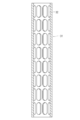
- FIG. 5 is a front view showing an example of an inner tubular member used in the hollow fiber extracorporeal blood perfusion type artificial lung according to the present invention.
- FIG. 1 is a cross-sectional view of a hollow fiber extracorporeal blood perfusion type artificial lung according to an embodiment of the present invention.
- FIG. 2 is an enlarged cross-sectional view of a porous hollow fiber membrane for gas exchange used in the hollow fiber extracorporeal
- FIG. 6 is a central vertical sectional view of the inner tubular member shown in FIG.
- FIG. 7 is a cross-sectional view taken along the line BB of FIG.
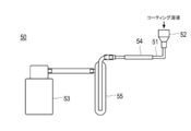
- FIG. 8 is a circuit diagram used when passing an organic solvent through the lumen of the hollow fiber membrane in Reference Example 1.
- FIG. 9 is a photograph before and after passing an organic solvent (acetone stained with rhodamine B) through the lumen of the hollow fiber membrane in Reference Example 1.
- FIG. 9A is an external photograph of the hollow fiber membrane before passing the liquid under visible light.
- FIG. 9B is an external photograph of the hollow fiber membrane after passing the liquid under visible light.
- FIG. 9C is a photograph of the paper wrapped around the outer surface of the hollow fiber membrane after passing the liquid under visible light.
- FIG. 9A is an external photograph of the hollow fiber membrane before passing the liquid under visible light.
- FIG. 9B is an external photograph of the hollow fiber membrane after passing the liquid under visible light.
- FIG. 9C is a photograph of the paper wrapped around the outer
- FIG. 9D is an external photograph of the hollow fiber membrane after passing the liquid under UV irradiation.
- FIG. 9E is a photograph of the paper wrapped around the outer surface of the hollow fiber membrane after passing the liquid under UV irradiation.
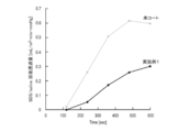
- FIG. 10 is a graph showing gas permeability in Examples and Comparative Examples.
- FIG. 11 is a graph showing plasma leak resistance in Examples and Comparative Examples.
- the present invention is a method for producing an artificial lung having a plurality of porous hollow fiber membranes for gas exchange, in which a silicone compound is dissolved in an organic solvent having a surface tension of less than 70 dyn / cm to prepare a coating liquid. , 50 hPa or more and 150 hPa or less, the inner surface of the hollow fiber membrane is brought into contact with the coating liquid, and a silicone compound (a silicone compound used for preparing the coating liquid and / or the silicone compound) is applied to the inner surface.
- the present invention relates to a production method comprising forming a coat layer containing a crosslinked product.
- the coating liquid can be easily passed through the lumen of the hollow fiber membrane by using an organic solvent having a surface tension of less than 70 dyn / cm.
- the coating liquid tends to leak to the outer surface of the hollow fiber membrane through the pores of the hollow fiber membrane. ..
- a coat layer containing a silicone compound is formed on the outer surface of the hollow fiber membrane.
- a coat layer containing a silicone compound is formed on the inner surface of the hollow fiber membrane.
- the coating film containing the water-soluble antithrombotic polymer compound is usually an aqueous coating in which the antithrombotic polymer compound is dispersed in an aqueous solvent containing water (preferably containing water in an amount of 85% by mass or more). It is formed by bringing the liquid into contact with the inner or outer surface of the hollow fiber membrane.
- a coating layer containing a silicone compound is formed on the outer surface of the hollow fiber membrane by the production method of JP-A-2002-035116, a coating layer may be further laminated on the coat layer containing the silicone compound on the outer surface.
- a coat layer containing a silicone compound is formed on the inner surface of the hollow fiber membrane, and a film containing a water-soluble antithrombotic polymer compound is formed on the outer surface.
- an artificial lung having plasma leak resistance can be provided.
- X to Y indicating a range includes X and Y and means "X or more and Y or less”. Unless otherwise specified, the operation and physical properties are measured under the conditions of room temperature (20 to 25 ° C.) / relative humidity of 40 to 50% RH. Further, “A and / or B” means both A and B, or either A or B.
- the artificial lung according to one embodiment of the present invention is an artificial lung having a plurality of porous hollow fiber membranes for gas exchange, and the hollow fiber membrane has an inner surface forming a lumen and an outer surface.
- a coat layer containing a silicone compound (a silicone compound used for preparing the coating liquid and / or a crosslinked product of the silicone compound) is formed on the inner surface thereof, and an antithrombotic polymer compound is contained on the outer surface. It is characterized in that a film is formed.
- FIG. 1 is a cross-sectional view of a hollow fiber extracorporeal blood perfusion type artificial lung according to an embodiment of the present invention.
- FIG. 2 is an enlarged cross-sectional view of a porous hollow fiber membrane for gas exchange used in the hollow fiber extracorporeal blood perfusion type artificial lung according to the embodiment of the present invention.
- a hollow fiber extracorporeal blood perfusion type artificial lung is also simply referred to as “hollow fiber membrane type artificial lung” or “artificial lung”.
- the porous hollow fiber membrane for gas exchange is also simply referred to as "porous hollow fiber membrane” or "hollow fiber membrane”.
- a large number of gas exchange porous hollow fiber membranes 3 are housed in the housing 2.
- the hollow fiber membrane 3 is provided with a passage (lumen) 3d forming a gas chamber in the center.
- the hollow fiber membrane 3 has openings 3e and 3f that communicate the outer surface 3a'and the inner surface 3c'.
- a coat layer 16 containing a silicone compound is formed on the inner surface 3c'of the hollow fiber membrane 3 through which the oxygen-containing gas flows.
- a film 18 containing an antithrombotic polymer compound is formed on the outer surface 3a'(in some cases, the outer surface 3a' and the outer surface layer 3a) of the hollow fiber membrane 3 serving as a blood contact portion.
- the coat layer 16 may contain other components in addition to the silicone compound.
- the other components are not particularly limited, and examples thereof include polyolefins, aliphatic hydrocarbons, inorganic fine particles, and cross-linking agents.
- the coat layer 16 is composed only of the silicone compound.
- the coating 18 may contain other components in addition to the antithrombotic polymer compound.
- the other components are not particularly limited, and examples thereof include other antithrombotic substances (for example, heparin), cross-linking agents, thickeners, preservatives, pH adjusters, and the like.
- the coat layer 16 containing the silicone compound may be formed on at least a part of the inner surface 3c'of the hollow fiber membrane 3 through which the oxygen-containing gas flows, but the gas exchange performance is maintained during long-term use (plasma leak resistance). It is preferable that it is formed on the entire inner surface 3c'from the viewpoint of improving the effect of improving the temperature and suppressing the wet rung. In the embodiment shown in FIG. 2, the coat layer 16 containing the silicone compound is formed so as to close the opening 3f of the pores on the inner surface 3c'side over the entire inner surface 3c'. Since the coat layer 16 containing the silicone compound has high gas permeability, it can have sufficient gas exchange performance. Further, the coat layer 16 containing the silicone compound may be present in the inner surface layer 3c (in some cases, the inner surface layer 3c and the inner layer 3b) of the hollow fiber membrane 3.
- the coating film 18 containing the antithrombotic polymer compound may be formed on at least a part of the outer surface 3a'which is the blood contact portion of the hollow fiber membrane 3, but is antithrombotic biocompatible (adhesion of platelets). / From the viewpoint of suppressing / preventing adhesion and suppressing / preventing activation of platelets), it is preferable that the film is formed on the entire outer surface 3a'. In the embodiment shown in FIG. 2, the coating film 18 containing the antithrombotic polymer compound may be present in the inner layer 3b (in some cases, the inner layer 3b and the inner surface layer 3c) of the hollow fiber membrane 3.
- the coating film 18 containing the antithrombotic polymer compound is substantially not present in the inner layer 3b (in some cases, the inner layer 3b and the inner surface layer 3c) of the hollow fiber membrane 3".
- the antithrombotic polymer compound is formed in the hollow fiber membrane 3 by applying a colloidal solution of the antithrombotic polymer compound to form a film. It can be in a form that is substantially nonexistent in the inner layer 3b or the inner layer 3c.
- the hollow fiber membrane type artificial lung 1 includes a housing 2 having a blood inlet 6 and a blood outlet 7, and a large number of gas exchange porous hollow fiber membranes 3 housed in the housing 2. It has a hollow fiber membrane bundle and a pair of partition walls 4 and 5 that tightly support both ends of the hollow fiber membrane bundle on the housing 2, and between the partition walls 4 and 5 and the inner surface of the housing 2 and the outer surface of the hollow fiber membrane 3. It has a blood chamber 12 formed in, a gas chamber formed inside the hollow fiber membrane 3, and a gas inlet 8 and a gas outlet 9 communicating with the gas chamber.
- the hollow fiber membrane type artificial lung 1 of the present embodiment includes a tubular housing 2, an aggregate of gas exchange hollow fiber membranes 3 housed in the tubular housing 2, and a hollow fiber membrane 3. It has partition walls 4 and 5 that hold both ends in the housing 2 in a liquid-tight manner, and the inside of the tubular housing 2 is divided into a blood chamber 12 which is a first fluid chamber and a gas chamber which is a second fluid chamber.
- the tubular housing 2 is provided with a blood inlet 6 and a blood outlet 7 that communicate with the blood chamber 12.
- a cap-shaped gas inflow having a gas inflow port 8 which is a second fluid inflow port communicating with a gas chamber which is an internal space of the hollow fiber membrane 3 is provided above the partition wall 4 which is an end portion of the tubular housing 2.
- the side header 10 is attached. Therefore, the gas inflow chamber 13 is formed by the outer surface of the partition wall 4 and the inner surface of the gas inflow side header 10.
- the gas inflow chamber 13 communicates with a gas chamber formed by the internal space of the hollow fiber membrane 3.
- a cap-shaped gas outflow side header 11 provided below the partition wall 5 and having a gas outflow port 9 which is a second fluid outflow port communicating with the internal space of the hollow fiber membrane 3 is attached. Therefore, the gas outflow chamber 14 is formed by the outer surface of the partition wall 5 and the inner surface of the gas outflow side header 11.
- the hollow fiber membrane 3 is a porous membrane made of a hydrophobic polymer material, and is the same as the hollow fiber membrane used for known artificial lungs, and is not particularly limited. Since the hollow fiber membrane (particularly the inner surface of the hollow fiber membrane) is made of a hydrophobic polymer material in this way, leakage of plasma components can be suppressed.
- a hydrophobic polymer material similar to the hollow fiber membrane used for known artificial lungs can be used. Specific examples thereof include polyolefin resins such as polypropylene, polyethylene and polymethylpentene, and polymer materials such as polysulfone, polyacrylonitrile, polytetrafluoroethylene and cellulose acetate.
- polyolefin resins are preferably used, polypropylene and polymethylpentene are more preferred, and polypropylene is even more preferred. That is, in the preferred embodiment of the present invention, at least a part of the hollow fiber membrane (preferably the entire hollow fiber membrane) is formed of the polyolefin resin. In a more preferred embodiment of the invention, at least a portion of the hollow fiber membrane (preferably the entire hollow fiber membrane) is made of polypropylene or polymethylpentene.
- the inner diameter of the hollow fiber membrane is not particularly limited, but is preferably 50 to 300 ⁇ m, more preferably 80 to 200 ⁇ m.
- the outer diameter of the hollow fiber membrane is not particularly limited, but is preferably 100 to 400 ⁇ m, and more preferably 130 to 200 ⁇ m.
- the wall thickness (thickness) of the hollow fiber membrane is preferably 20 ⁇ m or more and less than 50 ⁇ m, more preferably 25 ⁇ m or more and less than 50 ⁇ m, still more preferably 25 to 45 ⁇ m, still more preferably 25 to 40 ⁇ m, still more preferably 25 to 35 ⁇ m, particularly. It is preferably 25 to 30 ⁇ m.
- the "thickness (thickness) of the hollow fiber membrane” means the wall thickness between the inner surface and the outer surface of the hollow fiber membrane, and the formula: [(outside the hollow fiber membrane). Diameter)-(Inner diameter of hollow fiber membrane)] / 2.
- the porosity of the hollow fiber membrane is preferably 5 to 90% by volume, more preferably 10 to 80% by volume, and particularly preferably 30 to 60% by volume.
- the pore size of the hollow fiber membrane is preferably 0.01 to 5 ⁇ m, more preferably 0.05 to 1 ⁇ m.
- the method for producing the hollow fiber membrane is not particularly limited, and a known method for producing the hollow fiber membrane can be applied in the same manner or appropriately modified.
- the hollow fiber membrane is preferably formed with micropores formed on the wall by a stretching method or a solid-liquid phase separation method.
- the "pore diameter of the hollow fiber membrane” refers to the average diameter of the opening on the side (outer surface side) coated with the antithrombotic polymer compound.
- the pore size of the hollow fiber membrane is measured by the method described below.
- the side (outer surface) of the hollow fiber membrane coated with the antithrombotic polymer compound is photographed with a scanning electron microscope (SEM).
- SEM scanning electron microscope
- image processing is performed on the obtained SEM image, the pore portion (opening) is inverted to white, and the other portion is inverted to black, and the number of pixels in the white portion is measured.
- the boundary level of binarization is an intermediate value between the difference between the whitest part and the blackest part.
- the pore area is calculated based on the number of pixels of each pore obtained in this way and the resolution ( ⁇ m / pixel) of the SEM image. From the obtained pore area, the diameter of each pore is calculated by regarding the pores as circular, and a statistically significant number, for example, the diameter of 500 pores is randomly extracted. The arithmetic mean is defined as the "pore diameter of the hollow fiber membrane".
- the same material as that used for the known artificial lung housing can be used.
- specific examples thereof include hydrophobic synthetic resins such as polycarbonate, acrylic / styrene copolymer, and acrylic / butylene / styrene copolymer.
- the shape of the housing 2 is not particularly limited, but is preferably cylindrical and transparent, for example. By forming it with a transparent body, it is possible to easily check the inside.
- the storage amount of the hollow fiber membrane in this embodiment is not particularly limited, and the same amount as that of a known artificial lung can be applied.
- about 5,000 to 100,000 porous hollow fiber membranes 3 are housed in the housing 2 in parallel in the axial direction thereof.
- the hollow fiber membrane 3 is fixed in a liquidtight state by the partition walls 4 and 5 with both ends of the hollow fiber membrane 3 open at both ends of the housing 2.
- the partition walls 4 and 5 are formed of a potting agent such as polyurethane or silicone rubber.
- the portion of the housing 2 sandwiched between the partition walls 4 and 5 is partitioned into a gas chamber on the inner side of the hollow fiber membrane 3 and a blood chamber 12 on the outer side of the hollow fiber membrane 3.
- the gas inflow side header 10 having the gas inflow port 8 and the gas outflow side header 11 having the gas outflow port 9 are liquidtightly attached to the housing 2.
- These headers may also be made of any material, for example the hydrophobic synthetic resin used in the housings described above.
- the header may be attached by any method.
- the header may be attached to the housing 2 by fusion using ultrasonic waves, high frequency, induction heating, etc., adhesion using an adhesive, or mechanical fitting. Attached to.
- a tightening ring (not shown) may be used.
- the blood contact portions (inner surface of the housing 2 and outer surface of the hollow fiber membrane 3) of the hollow fiber membrane type artificial lung 1 are all formed of a hydrophobic material.
- the coating (coating) of the antithrombotic polymer compound is selectively formed on the outer surface (external perfusion type) of the hollow fiber membrane. Therefore, blood (particularly plasma component) does not easily or does not penetrate into the pores of the hollow fiber membrane. Therefore, leakage of blood (particularly plasma component) from the hollow fiber membrane can be effectively suppressed / prevented.
- the antithrombotic polymer compound is substantially absent in the inner layer 3b of the hollow fiber membrane and the inner surface layer 3c of the hollow fiber membrane, the inner layer 3b of the hollow fiber membrane and the inner surface layer 3c of the hollow fiber membrane may be formed. Since the hydrophobic state of the material is maintained, leakage of high blood (particularly plasma component) can be more effectively suppressed / prevented. Therefore, the artificial lung obtained by the method of the present invention can maintain a high gas exchange capacity for a long period of time.
- the coating of the antithrombotic polymer compound according to the present embodiment is essentially formed on the outer surface of the hollow fiber membrane of the artificial lung, but in addition to the outer surface, other constituent members (for example, the entire blood contact portion). May be formed in.
- other constituent members for example, the entire blood contact portion.
- the coating of the antithrombotic polymer compound according to the present invention is preferably formed on other constituent members with which blood comes into contact, but the hollow fiber membrane or hollow fiber membrane other than the blood contact portion.
- the other portion (for example, the portion buried in the partition wall) may not be coated with the antithrombotic polymer compound. Since such a portion does not come into contact with blood, there is no particular problem even if the antithrombotic polymer compound is not coated.
- FIG. 3 is a cross-sectional view showing another embodiment of the artificial lung obtained by the method of the present invention.
- FIG. 4 is a cross-sectional view taken along the line AA of FIG.
- the artificial lung (hollow fiber membrane extracorporeal blood perfusion type artificial lung) 20 has an inner tubular member 31 having an opening 32 for blood flow on the side surface and a large number of gases wound around the outer surface of the inner tubular member 31.
- a tubular hollow fiber membrane bundle 22 made of a replacement porous hollow fiber membrane 3 a housing 23 for accommodating the tubular hollow fiber membrane bundle 22 together with an inner tubular member 31, and a state in which both ends of the hollow fiber membrane 3 are opened.
- the partition walls 25 and 26 for fixing both ends of the tubular hollow fiber membrane bundle 22 to the housing, the blood inlet 28 and the blood outlets 29a and 29b communicating with the blood chamber 17 formed in the housing 23, and the hollow fiber. It has a gas inflow port 24 and a gas outflow port 27 that communicate with the inside of the membrane 3.
- the housing 23 includes an outer tubular member 33 for accommodating the inner tubular member 31, and the tubular hollow fiber membrane bundle 22 is an inner cylinder. It is housed between the shape member 31 and the outer tubular member 33, and further, the housing 23 has one of a blood inlet or a blood outlet communicating with the inside of the inner tubular member and blood communicating with the inside of the outer tubular member. It has either an inlet or a blood outlet.
- the housing 23 is housed in the outer tubular member 33 and the inner tubular member 31, and the inner tubular body 35 whose tip is opened in the inner tubular member 31.
- a blood inlet 28 is formed at one end (lower end) of the inner cylinder 35, and two outwardly extending blood outlets 29a and 29b are formed on the side surface of the outer tubular member 33.
- the number of blood outlets may be one or a plurality.
- the tubular hollow fiber membrane bundle 22 is wound around the outer surface of the inner tubular member 31. That is, the inner tubular member 31 is the core of the tubular hollow fiber membrane bundle 22.
- the tip of the inner tubular body 35 housed inside the inner tubular member 31 is open near the first partition wall 25. Further, a blood inflow port 28 is formed at a lower end portion protruding from the inner tubular member 31.
- the inner tubular member 35, the inner tubular member 31 around which the hollow fiber membrane bundle 22 is wound around the outer surface, and the outer tubular member 33 are arranged substantially concentrically. Then, one end (upper end) of the inner tubular member 31 and one end (upper end) of the outer tubular member 33 around which the hollow fiber membrane bundle 22 is wound are concentrically positioned by the first partition wall 25. While being maintained, the space formed between the inside of the inner tubular member and the outer tubular member 33 and the outer surface of the hollow fiber membrane is in a liquid-tight state that does not communicate with the outside.
- the second partition wall 26 maintains a concentric positional relationship between the two, and the space formed between the inner tubular body 35 and the inner tubular member 31 and the outer tubular member 33 and the hollow fiber.
- the space formed between the outer surface of the membrane and the outer surface is in a liquid-tight state that does not communicate with the outside.
- the partition walls 25 and 26 are formed of a potting agent such as polyurethane or silicone rubber.
- the blood inflow port 17a formed inside the inner tubular body 35, and the substantially tubular space formed between the inner tubular body 35 and the inner tubular member 31.
- the first blood chamber 17b is provided, and the second blood chamber 17c which is a substantially tubular space formed between the hollow fiber membrane bundle 22 and the outer tubular member 33 is provided, whereby blood is provided.
- a chamber 17 is formed.
- the blood flowing in from the blood inlet 28 flows into the blood inlet 17a, rises in the inner cylinder 35 (blood inlet 17a), and flows out from the upper end 35a (open end) of the inner cylinder 35.
- Flows into the first blood chamber 17b passes through the opening 32 formed in the inner tubular member 31, comes into contact with the hollow fiber membrane, exchanges gas, and then flows into the second blood chamber 17c. Then, it flows out from the blood outlets 29a and 29b.
- a gas inflow member 41 having a gas inflow port 24 is fixed to one end of the outer tubular member 33, and similarly, a gas having a gas outlet 27 at the other end of the outer tubular member 33.
- the outflow member 42 is fixed.
- the blood inlet 28 of the inner cylinder 35 penetrates the gas outflow member 42 and projects to the outside.
- the outer tubular member 33 is not particularly limited, but a cylindrical body, a polygonal cylinder, a member having an elliptical cross section, or the like can be used. It is preferably a cylinder.
- the inner diameter of the outer tubular member is not particularly limited and may be the same as the inner diameter of the outer tubular member used in known artificial lungs, but is preferably about 32 to 164 mm.
- the effective length of the outer tubular member (the length of the portion of the total length that is not buried in the partition wall) is also not particularly limited, and is the same as the effective length of the outer tubular member used for a known artificial lung. Although it is possible, it is preferably about 10 to 730 mm.
- the shape of the inner tubular member 31 is not particularly limited, but for example, a cylindrical body, a polygonal cylinder, or an elliptical cross section can be used. It is preferably a cylinder.
- the outer diameter of the inner tubular member is not particularly limited and may be the same as the outer diameter of the inner tubular member used in known artificial lungs, but is preferably about 20 to 100 mm.
- the effective length of the inner tubular member (the length of the portion of the total length that is not buried in the partition wall) is also not particularly limited, and is the same as the effective length of the inner tubular member used for a known artificial lung. Although it is possible, it is preferably about 10 to 730 mm.
- the inner tubular member 31 is provided with a large number of blood circulation openings 32 on the side surface.
- the size of the opening 32 is preferably large in total area as long as the required strength of the tubular member is maintained. Examples of satisfying such conditions are shown in FIG. 5 which is a front view, FIG. 6 which is a central vertical sectional view of FIG. 5, and FIG. 7 which is a sectional view taken along line BB of FIG.
- a plurality of openings 32 are provided on the outer peripheral surface of the tubular member at equal intervals (for example, 4 to 24, 8 in the longitudinal direction in the figure), and annular arrangement openings are provided at equal intervals in the axial direction of the tubular member. It is preferable to provide a plurality of sets (8 sets / circumference in the figure).
- the opening shape may be a circle, a polygon, an ellipse, or the like, but an oval shape as shown in FIG. 5 is preferable.
- the shape of the inner cylinder 35 is not particularly limited, but for example, a cylinder, a polygonal cylinder, or an elliptical cross section can be used. It is preferably a cylinder.
- the distance between the tip opening of the inner cylinder 35 and the first partition wall 25 is not particularly limited, and the same distance as that used for a known artificial lung can be applied, but about 20 to 50 mm is preferable. be.
- the inner diameter of the inner cylinder 35 is also not particularly limited and may be the same as the inner diameter of the inner cylinder used for a known artificial lung, but about 10 to 30 mm is preferable.
- the thickness of the tubular hollow fiber membrane bundle 22 is not particularly limited and may be the same as the thickness of the tubular hollow fiber membrane bundle used in known artificial lungs, but is preferably 5 to 35 mm, particularly 10 mm to 28 mm. Is preferable. Further, the filling rate of the hollow fiber membrane in the tubular space formed between the outer surface and the inner side surface of the tubular hollow fiber membrane bundle 22 is also not particularly limited, and the filling rate in a known artificial lung is similarly applied. Although it is possible, 40 to 85% is preferable, and 45 to 80% is particularly preferable.
- the outer diameter of the hollow fiber membrane bundle 22 may be the same as the outer diameter of the hollow fiber membrane bundle used in known artificial lungs, but is preferably 30 to 170 mm, and particularly preferably 70 to 130 mm.
- the gas exchange membrane the one described above is used.
- the hollow fiber membrane bundle 22 is formed by winding the hollow fiber membrane around the inner tubular member 31, specifically, forming the hollow fiber membrane bobbin with the inner tubular member 31 as the core. Both ends of the bobbin can be formed by fixing both ends with a partition wall and then cutting both ends of the hollow fiber membrane bobbin together with the inner tubular member 31 which is the core. By this cutting, the hollow fiber membrane opens on the outer surface of the partition wall.
- the method for forming the hollow fiber membrane is not limited to the above method, and other known methods for forming the hollow fiber membrane may be used in the same manner or appropriately modified.
- one or a plurality of hollow fiber membranes are wound around the inner tubular member 31 at the same time so that the hollow fiber membranes that are substantially parallel and adjacent to each other are substantially at regular intervals. Thereby, the drift of blood can be suppressed more effectively.
- the distance between the hollow fiber membranes and the adjacent hollow fiber membranes is not limited to the following, but it is preferably 1/10 to 1/1 of the outer diameter of the hollow fiber membranes.
- the hollow fiber membrane preferably has a distance of 30 to 200 ⁇ m from the adjacent hollow fiber membrane.
- the hollow fiber membrane bundle 22 has one or a plurality of hollow fiber membranes (preferably 2 to 16) at the same time, and all the adjacent hollow fiber membranes are inside at substantially a constant interval. It is formed by being wound around the tubular member 31, and when the hollow fiber membrane is wound on the inner tubular member, a rotating body and a hollow fiber membrane for rotating the inner tubular member 31 are provided. It is preferable that the winder for knitting is formed by being wound around the inner tubular member 31 by moving under the condition of the following formula (1).
- n which is the relationship between the number of rotations of the winding rotating body and the number of reciprocating winders, is not particularly limited, but is usually 1 to 5, preferably 2 to 4.
- a coat layer 16 containing a silicone compound is formed on the inner surface 3c'of the hollow fiber membrane 3 through which the oxygen-containing gas flows.
- a film 18 containing an antithrombotic polymer compound is formed on the outer surface 3a'(in some cases, the outer surface 3a' and the outer surface layer 3a) of the hollow fiber membrane 3 serving as a blood contact portion.
- the preferred form of the hollow fiber membrane is not particularly limited, but a form similar to that described in FIG. 1 can be adopted.
- the production method is a method for producing an artificial lung having a plurality of porous hollow fiber membranes for gas exchange, and a coating liquid is prepared by dissolving a silicone compound in an organic solvent having a surface tension of less than 70 dyn / cm. Then, under a negative pressure of 50 hPa or more and 150 hPa or less, the inner surface of the hollow fiber membrane is brought into contact with the coating liquid, and a silicone compound (a silicone compound used for preparing the coating liquid and / or the silicone compound) is applied to the inner surface. It is characterized by forming a coat layer containing a crosslinked product of the above.
- the silicone compound is dissolved in an organic solvent having a surface tension of less than 70 dyn / cm to prepare a coating liquid (hereinafter, simply “(1) coating liquid preparation step", “coating”. Also referred to as “liquid preparation step” or “step (1)”). Then, the inner surface of the hollow fiber membrane is brought into contact with the coating liquid under a negative pressure of 50 hPa or more and 150 hPa or less (hereinafter, simply “(2) coating liquid coating step”, “coating liquid coating step” or “step (2)). Also called).
- each step will be described.
- Coating liquid preparation step In this step, a coating liquid for coating on the inner surface of the hollow fiber membrane is prepared.
- the coating liquid contains a silicone compound and an organic solvent having a specific surface tension.
- the silicone compound has a function of suppressing the leakage of plasma from the outer surface side to the inner surface side of the hollow fiber membrane. Further, in the hollow fiber membrane type artificial lung, there may be a problem that the gas exchange performance is lowered due to the phenomenon of wet rung in which the water vaporized from the blood is accumulated in the lumen of the hollow fiber membrane. It also has the function of suppressing rungs.
- the silicone compound can be used without particular limitation as long as it is a polymer compound having a siloxane bond (Si—O—Si) in the main skeleton. Above all, the silicone compound is preferably a silicone compound represented by the following formula (1) because a coat layer having excellent plasma leak resistance can be formed. That is, according to a preferred embodiment of the present invention, the silicone compound is provided with a method for producing an artificial lung represented by the following formula (1).
- R 1 to R 8 are independently an alkyl group having 1 or more and 6 or less carbon atoms, an aromatic hydrocarbon group having 6 or more and 30 or less carbon atoms, or an aromatic hydrocarbon group having 1 or more and 6 or less carbon atoms.
- n is 1 or more and 100,000 or less.
- R 1 to R 8 are independently alkyl groups having 1 or more and 6 or less carbon atoms or aromatic hydrocarbon groups having 6 or more and 30 or less carbon atoms.
- at least one of R 1 to R 8 is a group consisting of an ethylenically unsaturated bond-containing group having 1 to 6 carbon atoms, an amino group, a hydroxyl group, a carboxy group, a maleimide group, a thiol group and a halogen group. It is preferably a reactive group selected from.
- At least one of R 1 to R 3 and at least one of R 6 to R 8 are independently each of an ethylenically unsaturated bond-containing group having 1 or more and 6 or less carbon atoms, amino.
- the rest of 8 independently represent an alkyl group having 1 or more and 6 or less carbon atoms or an aromatic hydrocarbon group having 6 or more and 30 or less carbon atoms.
- one of R 1 to R 3 and one of R 6 to R 8 independently have an ethylenically unsaturated bond-containing group having 1 or more and 6 or less carbon atoms, an amino group, and the like.
- the cross-linking reaction proceeds in the process of forming the coat layer (for example, the process of drying the organic solvent), and a cross-linked product of the silicone compound is produced. sell. As a result, the adhesion and durability of the coat layer can be improved.
- the silicone compound used for preparing the coating liquid preferably the silicone compound represented by the formula (1)
- the silicone compound is contained in the coating layer formed on the inner surface of the hollow fiber membrane as it is. It can be.
- the silicone compound used for preparing the coating liquid preferably the silicone compound represented by the formula (1)
- the coating layer formed on the inner surface of the hollow yarn film has a coating layer.
- Silicone compounds used in the preparation of coating solutions ie, uncrosslinked silicone compounds
- / or crosslinked products of the silicone compounds may be included. That is, the coat layer formed on the inner surface of the hollow fiber membrane may contain a silicone compound used for preparing a coating liquid and / or a crosslinked product of the silicone compound.
- Examples of the alkyl group having 1 to 6 carbon atoms or the aromatic hydrocarbon group having 6 to 30 carbon atoms in the formula (1) include a methyl group, an ethyl group, an n-propyl group, a phenyl group, a fluorescein and a derivative thereof.
- the origin group is mentioned.
- examples of the derivative of fluorescein include fluorescein isothiocyanate, N-hydroxysuccinimide fluorescein, Oregon green, Tokyo green, SNAFL, carboxyfluorescein, carboxyfluorescein diacetate, and aminofluorescein.
- a methyl group and an ethyl group are preferable, and a methyl group is more preferable, from the viewpoint of fluidity and Young's modulus after curing.
- the ethylenically unsaturated bond-containing group having 1 to 6 carbon atoms include a vinyl group, a vinyloxy group, an allyl group, an allyloxy group, a propenyl group, and a propenyloxy group.
- the functional group containing an amino group include an amino group and an aminophenyl group.
- the functional group containing a hydroxyl group include a hydroxyl group, a phenol group, and a catechol group.
- Examples of the functional group containing a carboxy group include a carboxy group and a maleic acid group.
- Examples of the functional group containing a maleimide group include a maleimide group.
- Examples of the functional group containing a thiol group include a thiol group and a thiophenol group.
- Examples of the halogen group include a fluoro group, a chloro group, a bromo group and an iodine group. Among them, a vinyloxy group, an allyloxy group, and an allyl group are preferable, and a vinyloxy group is more preferable, because the cross-linking reactivity is good.
- N in the formula (1) is not particularly limited, but is preferably 1 or more and 100,000 or less, and more preferably 1 or more and 10,000 or less.
- the liquid can be passed through the fiber lumen under negative pressure.
- silicone compound either a commercially available product or a synthetic product may be used.
- examples of commercially available products include SYLGARD (registered trademark) 184 and 186 manufactured by Dow Corning.
- One type of silicone compound may be used alone, or two or more types may be used in combination.
- the concentration of the silicone compound in the coating liquid is not particularly limited, but is preferably 10 mg / mL or more and less than 800 mg / mL from the viewpoint of improving the liquid permeability of the coating liquid in the lumen of the hollow fiber membrane. It is preferably 20 to 400 mg / mL, and more preferably 100 to 300 mg / mL.
- the concentration is preferably 100 to 400 mg / mL, preferably 100 to 300 mg / mL, from the viewpoint of forming a coat layer having a sufficient thickness. More preferably, it is mL.
- a coat layer having a sufficient thickness can be formed even if the concentration is low, so the amount is preferably 10 to 100 mg / mL, preferably 20 to 70 mg. More preferably, it is / mL.
- Organic solvent is used for the purpose of dissolving the silicone compound.
- the organic solvent is required to have a surface tension of less than 70 dyn / cm in order to allow the coating liquid to pass through the lumen of the hollow fiber membrane. If the surface tension of the organic solvent is 70 dyn / cm or more, the solubility of the silicone compound is lowered and the coating liquid is difficult to pass through, so that the coating layer may not be formed satisfactorily.
- the surface tension of the organic solvent is preferably 50 dyn / cm or less, more preferably 50 dyn / cm or less, from the viewpoint of improving the solubility of the silicone compound and improving the liquid permeability of the coating liquid in the lumen of the hollow fiber membrane. It is 40 dyn / cm or less, more preferably 30 dyn / cm or less.
- the lower limit of the surface tension is not particularly limited, but is preferably 15 dyn / cm or more from the viewpoint of allowing the coating liquid to flow through the hollow fiber without any problem and preventing the coating liquid from permeating through the pores of the hollow fiber membrane. be.
- the numerical range of the surface tension of the organic solvent is preferably 15 dyn / cm or more and less than 70 dyn / cm, more preferably 15 dyn / cm or more and 50 dyn / cm or less, and further preferably 15 dyn / cm or more and 40 dyn / cm or less. Yes, and particularly preferably 15 dyn / cm or more and 30 dyn / cm or less. In addition, 1 dyn / cm is 0.001 N / m.
- the surface tension of an organic solvent is 20 ° C. using a Du Noüy surface tensiometer (manufactured by Ito Seisakusho). Measure with. Specifically, a platinum ring is hung from the tip of a thin rod attached to the center of the steel wire, brought into contact with the liquid surface of the organic solvent at a horizontal position, and the knob is turned to twist the steel wire to pull up the platinum ring and pull the liquid. The moment away from the surface is read with a scale plate and a pointer, and the value is taken as the surface tension (dyn / cm) of the organic solvent.
- organic solvent examples include aromatic hydrocarbons such as toluene (28.5 dyn / cm) and xylene (28.4 dyn / cm), cyclohexane (25.3 dyn / cm), and n-hexane (18.4 dyn / cm).
- aromatic hydrocarbons such as toluene (28.5 dyn / cm) and xylene (28.4 dyn / cm), cyclohexane (25.3 dyn / cm), and n-hexane (18.4 dyn / cm).
- N-Heptane (20.1 din / cm)
- diisopropyl ether (17.1 din / cm
- methylhexyl ether (23.5 din / cm
- ethyl acetate 24.0 din / cm).
- n-hexane, cyclohexane, acetone, butyl alcohol, 1-propanol, isopropanol, chloroform, diethyl ether from the viewpoint that the silicone compound can be dissolved well and the organic solvent can be easily removed at a low boiling point.
- Aromatic hydrocarbons and fluorine-based solvents are preferable, and n-hexane and acetone are more preferable. Only one of these solvents may be used alone, or two or more of these solvents may be mixed and used.
- the organic solvent is selected from the group consisting of n-hexane, cyclohexane, acetone, butyl alcohol, 1-propanol, isopropanol, chloroform, diethyl ether, aromatic hydrocarbons and fluorine-based solvents.
- a method for producing an artificial lung which is at least one of the above-mentioned methods, is provided. As long as the surface tension of the solvent that dissolves the silicone compound is less than 70 dyn / cm, an organic solvent having a surface tension of 70 dyn / cm or more may be contained.
- the coating liquid may contain additives in addition to the above silicone compounds and organic solvents, if necessary.
- additives include carnauba wax, PDMS-PEG, and a cross-linking agent.
- the form of the hollow fiber membrane (material, inner diameter, outer diameter, wall thickness, porosity, pore diameter of pores) to which the coating liquid is applied has been described in the above item ⁇ Artificial lung>. , A detailed description is omitted here.
- the lumen of the hollow fiber membrane is set to a negative pressure of 50 hPa or more and 150 hPa or less, preferably 50 hPa or more and 100 hPa or less.
- the method of applying negative pressure is not particularly limited, but for example, negative pressure can be achieved by airtightly connecting one end of the vacuum pump (for example, a diaphragm pump) and the hollow fiber membrane and operating the vacuum pump. As described in Examples described later, the value of the indicated pressure of the vacuum pump shall be adopted as the atmospheric pressure.
- the method of contacting with the coating liquid is not particularly limited, and examples thereof include a method of injecting the coating liquid from the other end of the hollow fiber membrane connected to the vacuum pump (the end not connected to the vacuum pump). According to this method, the coating liquid moves to the end on the side to which the vacuum pump is connected, so that the coating liquid comes into contact with the inner surface of the hollow fiber membrane.
- the contact time between the inner surface of the hollow fiber membrane and the coating liquid is not particularly limited, but is preferably 5 to 180 seconds, more preferably 15 to 120 seconds, and even more preferably 30 to 60 seconds.
- the amount of the coating liquid to be brought into contact with the lumen of the hollow fiber membrane is preferably 10 to 10,000 mL / m 2 per film area, preferably 30 to 1, from the viewpoint of forming a coating layer having a desired thickness. more preferably 000mL / m 2, further preferably 40 ⁇ 200mL / m 2.
- the organic solvent contained in the coating film is dried.
- the drying method is not particularly limited, and examples thereof include methods such as vacuum drying and high temperature drying at normal pressure.
- the drying temperature in high temperature drying is preferably 45 to 80 ° C., and the drying time is preferably 1 to 48 hours. That is, according to a preferred embodiment of the present invention, it is a method for producing an artificial lung having a plurality of porous hollow fiber membranes for gas exchange, in which a silicone compound is dissolved in an organic solvent having a surface tension of less than 70 dyn / cm.
- the coating liquid is prepared ((1) coating liquid preparation step), and the inner surface of the hollow fiber membrane is brought into contact with the coating liquid under a negative pressure of 50 hPa or more and 150 hPa or less, and then the organic solvent is dried. ((2') Coating liquid coating / drying step), a production method comprising forming a coating layer containing a silicone compound on the inner surface is provided.
- the film thickness of the coat layer after drying is not particularly limited, but is preferably 0.1 to 10 ⁇ m, more preferably 0.5 to 7 ⁇ m, and even more preferably 1 to 5 ⁇ m.
- the film thickness of the coat layer is 0.1 ⁇ m or more, sufficient plasma leak resistance can be obtained.
- the film thickness of the coat layer is 10 ⁇ m or less, deterioration of gas exchange performance can be prevented.
- the operation of bringing the inner surface of the hollow fiber membrane into contact with the coating liquid under a negative pressure of 50 hPa or more and 150 hPa or less may be performed only once or a plurality of times.
- a coating layer having a sufficient thickness can be formed by performing the operation a plurality of times.
- the cycle of drying the organic solvent after the operation is set as one cycle and the cycle is repeated a plurality of times.
- the present invention is a method for producing an artificial lung having a plurality of porous hollow fiber membranes for gas exchange, in which a silicone compound is dissolved in an organic solvent having a surface tension of less than 70 dyn / cm.
- a silicone compound is dissolved in an organic solvent having a surface tension of less than 70 dyn / cm.
- the preparation steps (1) (1) coating liquid preparation step
- the above-mentioned It has a contact / drying step (2') ((2') coating liquid application / drying step) for drying the organic solvent, and by repeating the contact / drying step (2') a plurality of times, the inner surface is covered.
- a production method comprising forming a coat layer containing a silicone compound is provided.
- the number of times when the above operation or the above step (2') is repeated a plurality of times is not particularly limited, but is preferably 2 to 5 times, more preferably 2 to 4 times, still more preferably 2 or 3 times.
- a coat layer containing a silicone compound is formed on the inner surface of the hollow fiber membrane.
- the method for producing an artificial lung according to the present embodiment may optionally include further steps in addition to steps (1) and (2). Examples of other steps include the following (3) antithrombotic film forming step. The step is preferably performed after the steps (1) and (2).
- Antithrombotic film forming step In this step, a film containing an antithrombotic polymer compound is formed on the outer surface of the hollow fiber membrane. That is, according to a preferred embodiment of the present invention, there is provided a method for producing an artificial lung, which further comprises forming a film containing an antithrombotic polymer compound on the outer surface of the hollow fiber membrane.
- the method for forming the antithrombotic polymer compound and the coating film is not particularly limited, and a known method can be appropriately adopted.
- the antithrombotic polymer compound is a compound that imparts antithrombotic properties to an artificial lung by being applied to the outer surface of a hollow fiber membrane that is a blood contact portion.
- the antithrombotic polymer compound can be used without particular limitation as long as it has antithrombotic properties and biocompatibility. Among them, from the viewpoint of being excellent in the above properties, the antithrombotic polymer compound preferably has a structural unit derived from an alkoxyalkyl (meth) acrylate represented by the following formula (I).
- R 3 represents a hydrogen atom or a methyl group
- R 1 represents an alkylene group having 1 to 4 carbon atoms
- R 2 represents an alkyl group having 1 to 4 carbon atoms.
- the compound having the structural unit represented by the formula (I) has antithrombotic biocompatibility (effect of suppressing / preventing adhesion of platelets and effect of suppressing / preventing activation of platelets), particularly adhesion / adhesion of platelets. Has excellent suppression / prevention effect. Therefore, by using the compound having the above-mentioned structural unit, antithrombotic biocompatibility (effect of suppressing / preventing adhesion / adhesion of platelets and effect of suppressing / preventing activation of platelets), particularly adhesion / adhesion of platelets It is possible to manufacture an artificial lung having an excellent inhibitory / preventive effect.
- (meth) acrylate means “acrylate and / or methacrylate”. That is, “alkoxyalkyl (meth) acrylate” includes all cases of alkoxyalkyl acrylate only, alkoxyalkyl methacrylate only, and alkoxyalkyl acrylate and alkoxyalkyl methacrylate.
- R 1 represents an alkylene group having 1 to 4 carbon atoms.
- the alkylene group having 1 to 4 carbon atoms is not particularly limited, and includes a linear or branched alkylene group of a methylene group, an ethylene group, a trimethylene group, a tetramethylene group, and a propylene group.
- an ethylene group and a propylene group are preferable, and an ethylene group is particularly preferable in consideration of further improving the antithrombotic property and biocompatibility.
- R 2 represents an alkyl group having 1 to 4 carbon atoms.
- the alkyl group having 1 to 4 carbon atoms is not particularly limited, and is a straight chain of a methyl group, an ethyl group, a propyl group, an isopropyl group, a butyl group, an isobutyl group, a sec-butyl group, a tert-butyl group or There is an alkyl group of the branched chain.
- a methyl group and an ethyl group are preferable, and a methyl group is particularly preferable in consideration of further improving the antithrombotic property and biocompatibility.
- R 3 represents a hydrogen atom or a methyl group.
- alkoxyalkyl (meth) acrylate examples include methoxymethyl acrylate, methoxyethyl acrylate, methoxypropyl acrylate, ethoxymethyl acrylate, ethoxyethyl acrylate, ethoxypropyl acrylate, ethoxybutyl acrylate, propoxymethyl acrylate, and butoxyethyl acrylate.
- examples thereof include methoxybutyl acrylate, methoxymethyl methacrylate, methoxyethyl methacrylate, ethoxymethyl methacrylate, ethoxyethyl methacrylate, propoxymethyl methacrylate, butoxyethyl methacrylate and the like.
- methoxyethyl (meth) acrylate and methoxybutyl acrylate are preferable, and methoxyethyl acrylate (MEA) is particularly preferable, from the viewpoint of further improving the antithrombotic property and biocompatibility.
- the antithrombotic polymer compound is preferably polymethoxyethyl acrylate (PMEA).
- PMEA polymethoxyethyl acrylate
- the above-mentioned alkoxyalkyl (meth) acrylate may be used alone or in combination of two or more.
- the antithrombotic polymer compound according to the present invention preferably has a structural unit derived from alkoxyalkyl (meth) acrylate, and is composed of one or more structural units derived from alkoxyalkyl (meth) acrylate.
- the structure of the polymer (copolymer) is not particularly limited, and a random copolymer or an alternating copolymer is used. It may be a coalescence, a periodic copolymer, or a block copolymer.
- the terminal of the polymer is not particularly limited and is appropriately defined depending on the type of raw material used, but is usually a hydrogen atom.
- a monomer copolymerizable with the alkoxyalkyl (meth) acrylate when the antithrombotic polymer compound according to the present invention has another structural unit in addition to the structural unit derived from the alkoxyalkyl (meth) acrylate.
- the (copolymerizable monomer) is not particularly limited.
- the copolymerizable monomer preferably has no hydroxyl group or cationic group in the molecule.
- the copolymer may be a random copolymer, a block copolymer, or a graft copolymer, and can be synthesized by a known method such as radical polymerization, ionic polymerization, or polymerization using macromer.
- the ratio of the constituent units derived from the copolymerizable monomer to all the constituent units of the copolymer is not particularly limited, but the copolymerizable monomer is considered in consideration of antithrombotic property, biocompatibility and the like.
- the structural unit (other structural unit) derived from the above is more than 0 mol% and 50 mol% or less of all the structural units of the copolymer. If it exceeds 50 mol%, the effect of the alkoxyalkyl (meth) acrylate may be reduced.
- the weight average molecular weight of the antithrombotic polymer compound is not particularly limited, but is preferably 80,000 or more.
- the antithrombotic polymer compound is applied to the outer surface of the hollow fiber membrane in the form of an aqueous coating solution. Therefore, from the viewpoint of facilitating the preparation of a desired aqueous coating solution, the weight average molecular weight of the antithrombotic polymer compound is preferably less than 800,000. Within the above range, it is possible to suppress aggregation or precipitation of the compound in a solution containing an antithrombotic polymer compound, and to prepare a stable aqueous coating solution.
- the weight average molecular weight of the antithrombotic polymer compound is preferably more than 200,000 and less than 800,000, more preferably 210,000 or more and 600,000 or less, and 220,000 or more and 500,000. It is even more preferable that it is less than or equal to, and particularly preferably 230,000 or more and 450,000 or less.
- the "weight average molecular weight” is measured by gel permeation chromatography (GPC) using polystyrene as a standard substance and tetrahydrofuran (THF) as a mobile phase.
- GPC gel permeation chromatography
- the polymer to be analyzed is dissolved in THF to prepare a 10 mg / ml solution.
- a GPC system LC-20 manufactured by Shimadzu Corporation was attached with a GPC column LF-804 manufactured by Shodex Co., Ltd., THF was flowed as a mobile phase, and polystyrene was used as a standard substance for analysis.
- the GPC of the polymer is measured.
- the weight average molecular weight of the polymer to be analyzed is calculated based on this curve.
- the “low molecular weight polymer” means a polymer having a weight average molecular weight of less than 60,000. The method for measuring the weight average molecular weight is as described above.
- the antithrombotic polymer compound containing a structural unit derived from the alkoxyalkyl (meth) acrylate represented by the above formula (I) can be produced by a known method. Specifically, a monomer (copolymerizable monomer) that can be copolymerized with the alkoxyalkyl (meth) acrylate represented by the following formula (II) and the above alkoxyalkyl (meth) acrylate added as needed. ) Is stirred together with a polymerization initiator in a polymerization solvent to prepare a monomer solution, and the monomer solution is heated to obtain alkoxyalkyl (meth) acrylate or alkoxy. A method of (co) polymerizing an alkyl (meth) acrylate and a copolymerizable monomer added as needed is preferably used.
- the polymerization solvent that can be used in the preparation of the monomer solution is particularly one that can dissolve the alkoxyalkyl (meth) acrylate of the above formula (II) used and the copolymerizable monomer added as needed.
- water alcohols such as methanol, ethanol, propanol and isopropanol, aqueous solvents such as polyethylene glycol; aromatic solvents such as toluene, xylene and tetraline; and halogens such as chloroform, dichloroethane, chlorobenzene, dichlorobenzene and trichlorobenzene.
- methanol is preferable in consideration of the ease of dissolving the alkoxyalkyl (meth) acrylate and the ease of obtaining a polymer having a weight average molecular weight as described above.
- the monomer concentration in the monomer solution is not particularly limited, but by setting the concentration relatively high, the weight average molecular weight of the obtained antithrombotic polymer compound can be increased. Therefore, considering the ease of obtaining a polymer having a weight average molecular weight as described above, the monomer concentration in the monomer solution is preferably less than 50% by mass, more preferably 15% by mass. It is more than 50% by mass. Further, the monomer concentration in the monomer solution is more preferably 20% by mass or more and 48% by mass or less, and particularly preferably 25% by mass or more and 45% by mass or less. The monomer concentration means the total concentration of these monomers when two or more kinds of monomers are used.
- the polymerization initiator is not particularly limited, and a known one may be used. It is preferably a radical polymerization initiator in that it is excellent in polymerization stability, and specifically, persulfate such as potassium persulfate (KPS), sodium persulfate, ammonium persulfate; hydrogen peroxide, t-butylper.
- KPS potassium persulfate
- sodium persulfate sodium persulfate
- ammonium persulfate hydrogen peroxide
- t-butylper t-butylper
- Peroxides such as oxides and methyl ethyl ketone peroxides; azobisisobutyronitrile (AIBN), 2,2'-azobis (4-methoxy-2,4-dimethylvaleronitrile), 2,2'-azobis (2, 4-Dimethylvaleronitrile), 2,2'-azobis [2- (2-imidazolin-2-yl) propane] dihydrochloride, 2,2'-azobis [2- (2-imidazolin-2-yl) propane] Disulfate dihydrate, 2,2'-azobis (2-methylpropion amidine) dihydrochloride, 2,2'-azobis [N- (2-carboxyethyl) -2-methylpropion amidine)] hydrate, 3 -Hydroxy-1,1-dimethylbutylperoxyneodecanoate, ⁇ -cumylperoxyneodecanoate, 1,1,3,3-tetrabutylperoxyneodecanoate,
- a reducing agent such as sodium sulfite, sodium hydrogen sulfite, or ascorbic acid may be combined with the radical polymerization initiator and used as a redox-based initiator.
- the amount of the polymerization initiator to be blended is 0.0001 to 1 mol with respect to the total amount of the monomers (alkoxyalkyl (meth) acrylate and copolymerizable monomer added as needed; the same applies hereinafter).
- % Is preferable 0.001 to 0.8 mol% is more preferable, and 0.01 to 0.5 mol% is particularly preferable.
- the blending amount of the polymerization initiator is preferably 0.005 to 2 parts by mass with respect to 100 parts by mass of the monomer (when a plurality of types of monomers are used, the whole thereof), which is more preferable. Is 0.05 to 0.5 parts by mass. With such a compounding amount of the polymerization initiator, a polymer having a desired weight average molecular weight can be produced more efficiently.
- the above-mentioned polymerization initiator may be mixed with the monomer and the polymerization solvent as it is, or may be mixed with the monomer and the polymerization solvent in the form of a solution previously dissolved in another solvent.
- the other solvent is not particularly limited as long as it can dissolve the polymerization initiator, but the same solvent as the above-mentioned polymerization solvent can be exemplified.
- the other solvent may be the same as or different from the above-mentioned polymerization solvent, but is preferably the same solvent as the above-mentioned polymerization solvent in consideration of ease of control of polymerization and the like.
- the concentration of the polymerization initiator in the other solvent in this case is not particularly limited, but the amount of the polymerization initiator added is preferably more than 100 parts by mass of the other solvent in consideration of ease of mixing and the like. Is 0.1 to 10 parts by mass, more preferably 0.15 to 5 parts by mass, and even more preferably 0.2 to 1.8 parts by mass.
- alkoxyalkyl (meth) acrylate or alkoxyalkyl (meth) acrylate and other monomers are (co) polymerized.
- the polymerization method for example, a known polymerization method such as radical polymerization, anionic polymerization, or cationic polymerization can be adopted, and radical polymerization which is easy to produce is preferably used.
- the polymerization conditions are not particularly limited as long as the above-mentioned monomers (alkoxyalkyl (meth) acrylate or alkoxyalkyl (meth) acrylate and copolymerizable monomer) can be polymerized.
- the polymerization temperature is preferably 30 to 60 ° C, more preferably 40 to 55 ° C.
- the polymerization time is preferably 1 to 24 hours, preferably 3 to 12 hours. Under such conditions, a polymer having a high molecular weight as described above can be produced more efficiently. In addition, gelation in the polymerization step can be effectively suppressed / prevented, and high production efficiency can be achieved.
- a chain transfer agent e.g., a polymerization rate adjusting agent, a surfactant, and other additives may be appropriately used at the time of polymerization.
- the atmosphere in which the polymerization reaction is carried out is not particularly limited, and the polymerization reaction can be carried out in an atmosphere of an inert gas such as nitrogen gas or argon gas. Further, the reaction solution may be stirred during the polymerization reaction.
- the polymer after polymerization can be purified by a general purification method such as a reprecipitation method, a dialysis method, an ultrafiltration method, or an extraction method.
- a general purification method such as a reprecipitation method, a dialysis method, an ultrafiltration method, or an extraction method.
- purification by the reprecipitation method is preferable because a (co) polymer suitable for preparing an aqueous coating liquid can be obtained.
- the purified polymer can be dried by any method such as freeze-drying, vacuum-drying, spray-drying, or heat-drying, but from the viewpoint of having a small effect on the physical characteristics of the polymer, it is freeze-dried or vacuum-dried. Is preferable.
- the solvent used for preparing the solution containing the antithrombotic polymer compound is particularly limited as long as the aqueous coating solution can be prepared by appropriately dispersing the antithrombotic polymer compound. Not done.
- the solvent preferably contains water from the viewpoint of more effectively preventing the permeation of the aqueous coating liquid from the outer surface to the inner surface (the surface on the side where the oxygen-containing gas flows) of the pores of the hollow fiber membrane.
- the water is preferably pure water, ion-exchanged water or distilled water, and more preferably distilled water.
- the solvent other than water used for preparing the aqueous coating liquid is not particularly limited, but methanol and acetone are preferable in consideration of ease of control such as dispersibility of the antithrombotic polymer compound. ..
- the solvent other than water may be used alone or in the form of a mixture of two or more.
- methanol is preferable in consideration of further controllability such as dispersibility of the antithrombotic polymer compound. That is, the solvent is preferably composed of water and methanol.
- the mixing ratio of water and methanol is not particularly limited, but considering the dispersibility of the antithrombotic polymer compound and the ease of further control of the average particle size of the colloid, the mixing ratio of water: methanol (mass).
- the ratio) is preferably 6 to 32: 1, more preferably 10 to 25: 1. That is, the solvent is preferably composed of water and methanol in a mixing ratio (mass ratio) of 6 to 32: 1, and is composed of water and methanol in a mixing ratio (mass ratio) of 10 to 25: 1. Is more preferable.
- the order in which the solvent (for example, water and methanol) and the antithrombotic polymer compound are added is particularly limited.
- a solvent other than water preferably methanol
- the antithrombotic polymer compound is contained in water.
- the antithrombotic polymer compound can be easily dispersed.
- the rate of addition of the antithrombotic polymer compound-containing solution to water is not particularly limited, but it is preferable to add the antithrombotic polymer compound-containing solution to water at a rate of 5 to 100 g / min.
- the stirring time and stirring temperature when preparing the aqueous coating liquid are not particularly limited, but from the viewpoint that colloids having a uniform particle size can be easily formed and the colloids can be uniformly dispersed, a solution containing an antithrombotic polymer compound in water. It is preferable to stir for 1 to 30 minutes after adding the above, and it is more preferable to stir for 5 to 15 minutes.
- the stirring temperature is preferably 10 to 40 ° C, more preferably 20 to 30 ° C.
- the concentration of the antithrombotic polymer compound in the aqueous coating liquid is not particularly limited, but is preferably 0.01% by mass or more from the viewpoint of easily increasing the coating amount. Further, from the above viewpoint, the aqueous coating liquid preferably contains the antithrombotic polymer compound at a concentration of 0.05% by mass or more, and particularly preferably at a concentration of 0.1% by mass or more.
- the upper limit of the concentration of the antithrombotic polymer compound in the aqueous coating liquid is not particularly limited, but is 0.3% by mass or less in consideration of the ease of forming a film and the effect of reducing coating unevenness. It is preferably 0.2% by mass or less, and more preferably 0.2% by mass or less. Further, within such a range, a decrease in gas exchange ability due to an excessively thick film of the antithrombotic polymer compound can be suppressed.
- the aqueous coating liquid prepared as described above is applied (coated) on the outer surface of the hollow fiber membrane.
- the aqueous coating solution is brought into contact with (or circulated) the outer surface of the hollow fiber membrane.
- the outer surface of the hollow fiber membrane that is, the blood contact portion
- an antithrombotic polymer compound As a result, a coating film containing an antithrombotic polymer compound is formed on the outer surface of the hollow fiber membrane.
- the application of the aqueous coating liquid to the hollow fiber membrane may be performed before assembling the artificial lung as long as the aqueous coating liquid is brought into contact with (or is distributed) with the outer surface of the hollow fiber membrane.
- the method of contacting the outer surface of the hollow fiber membrane with an aqueous coating liquid containing an antithrombotic polymer compound is not particularly limited, but conventionally known methods such as filling and dip coating (immersion method) can be applied. .. Of these, filling is preferable in order to increase the coating amount of the antithrombotic polymer compound.
- the filling amount of the aqueous coating liquid is the film area (m 2 ) of the hollow fiber membrane. , 50 g / m 2 or more, more preferably 80 g / m 2 or more.
- the filling amount is 50 g / m 2 or more, a film containing a sufficient amount of the antithrombotic polymer compound can be formed on the surface of the hollow fiber membrane.
- the upper limit of the filling amount is not particularly limited, but is preferably 200 g / m 2 or less, and more preferably 150 g / m 2 or less.
- the "membrane area” refers to the area of the outer surface of the hollow fiber membrane, and is calculated from the product of the outer diameter, pi, number, and effective length of the hollow fiber membrane.
- the time for contacting the outer surface of the hollow fiber membrane with the aqueous coating liquid containing the antithrombotic polymer compound is also not particularly limited, but considering the coating amount, the ease of forming the coating film, the effect of reducing coating unevenness, and the like, It is preferably 0.5 minutes or more and 5 minutes or less, and more preferably 1 minute or more and 70 minutes or less.
- the contact temperature between the water-based coating liquid and the hollow fiber membrane takes into consideration the amount of coating, the ease of forming the coating film, the effect of reducing coating unevenness, and the like. Then, 5 to 40 ° C. is preferable, and 15 to 30 ° C. is more preferable.
- the amount of the antithrombotic polymer compound applied to the outer surface of the hollow fiber membrane is not particularly limited, but is preferably an amount such that the thickness of the film after drying is about 5 nm to 20 ⁇ m. If the above thickness cannot be obtained by one coating (contact), the coating step may be repeated until a desired thickness is obtained.
- a coating film made of the antithrombotic polymer compound according to the present invention is formed on the outer surface of the hollow fiber membrane.
- the drying conditions are not particularly limited as long as the coating (coating) with the antithrombotic polymer compound can be formed on the outer surface (further, the outer surface layer) of the hollow fiber membrane.
- the drying temperature is preferably 5 to 50 ° C, more preferably 15 to 40 ° C.
- the drying time is preferably 60 to 300 minutes, more preferably 120 to 240 minutes.
- the coating film may be dried by continuously or stepwise flowing a gas of preferably 5 to 40 ° C., more preferably 15 to 30 ° C.
- the type of gas is not particularly limited as long as it does not affect the coating film and can dry the coating film.
- Specific examples thereof include air and an inert gas such as nitrogen gas and argon gas.
- the amount of gas flowing is not particularly limited as long as the coating film can be sufficiently dried, but is preferably 5 to 150 L, more preferably 30 to 100 L.
- an artificial lung in which a coat layer containing a silicone compound is formed on the inner surface of the hollow fiber membrane and a film containing an antithrombotic polymer compound is formed on the outer surface of the hollow fiber membrane can be obtained. Therefore, according to the production method according to the present embodiment, it is possible to provide an artificial lung having desired antithrombotic property and plasma leak resistance.
- FIG. 8 one end of a polypropylene porous hollow fiber membrane 51 (outer diameter: 170 ⁇ m, inner diameter: 112 ⁇ m, wall thickness: 29 ⁇ m, pore diameter: 0.05 ⁇ m, porosity: 30% by volume).
- a circuit 50 having a liquid injection port 52 connected to the liquid injection port 52 and a diaphragm pump 53 connected to the other end was assembled. Paper 54 was wrapped around the outer surface of the hollow fiber membrane 51 so that the presence or absence of leakage of the coating liquid from the pores could be confirmed.
- Acetone (surface tension: 23.3 dyn / cm) stained with Rhodamine B was poured into the liquid injection port 52 in advance, and the pressure was reduced so that the indicated pressure of the diaphragm pump 53 was 50 hPa.
- the lumen of the hollow fiber membrane 51 was set to a negative pressure of 50 hPa, and acetone was passed through the lumen for 30 seconds. Acetone after passing the liquid was recovered by the trap 55.
- the hollow fiber membrane 51 and the paper 54 were removed from the circuit, and they were irradiated with UV in a dark room to confirm the presence or absence of fluorescence.
- fluorescence by rhodamine B is observed in the hollow fiber membrane 51 after passing the liquid.
- E of FIG. 9 no fluorescence was observed on the paper 54. From this, it was confirmed that rhodamine B adhered only to the inner surface of the hollow fiber membrane 51 and not to the outer surface without leaking from the pores of acetone.
- Reference example 2 The same operation as in Reference Example 1 was carried out except that the solvent was n-hexane (surface tension: 18.4 dyn / cm).
- Example 1 A coating solution was prepared by dissolving polydimethylsiloxane (PDMS, SYLGARD® 184) in n-hexane (surface tension: 18.4 din / cm) so as to have a concentration of 200 mg / mL. The same operation as in Reference Example 1 was carried out except that the coating liquid was passed through the lumen of the hollow fiber membrane 51 so as to be 40 mL / m 2 per membrane area.
- PDMS polydimethylsiloxane
- SYLGARD® 184 surface tension: 18.4 din / cm
- the hollow fiber membrane 51 and the paper 54 were removed from the circuit and visually observed. As a result, no leakage of the coating liquid was confirmed.
- the solvent remaining in the cavity of the hollow fiber membrane was dried to obtain a coated hollow fiber membrane having a coat layer having a thickness of 4 ⁇ m.
- Example 1 The coated hollow fiber membrane obtained in Example 1 was evaluated for gas permeability and plasma leak resistance.
- FIG. 10 is a bar graph in which the gas flow rate per unit (area / time) is taken on the vertical axis. The larger the value on the vertical axis, the better the gas permeability.
- the coated hollow fiber membrane has lower gas permeability than the uncoated hollow fiber membrane, but the gas permeability (1.0 mL / m 2 ⁇ min ⁇ mmHg or more) required for an artificial lung is required. ) was confirmed to be sufficiently provided.
- the coated hollow fiber membrane is potted with epoxy resin, and the hollow fiber is dissolved in a solution (SDS / saline solution) in which sodium dodecyl sulfate (SDS) is dissolved in a 0.9 w / v% sodium chloride aqueous solution to a concentration of 1 mg / mL. Filled the outside of the membrane. A pressure of 760 mmHg was applied to the SDS / saline solution, and the amount of the SDS / saline solution permeating from the outside of the hollow fiber membrane to the lumen was measured to evaluate the plasma leak resistance. The plasma leak resistance of the uncoated hollow fiber membrane was evaluated by the same method. The results are shown in FIG.
- FIG. 11 is a graph in which the vertical axis represents the permeation amount of the SDS / saline solution per unit (area / time), and the horizontal axis represents time. The smaller the value on the vertical axis, the better the plasma leak resistance.
- the coated hollow fiber membrane has significantly improved plasma leak resistance as compared with the uncoated hollow fiber membrane.
- Example 2 A coating solution was prepared by dissolving polydimethylsiloxane (PDMS, SYLGARD® 184) in n-hexane (surface tension: 18.4 din / cm) so as to have a concentration of 20 mg / mL. The same operation as in Reference Example 1 was carried out except that the coating liquid was passed through the lumen of the hollow fiber membrane 51 so as to be 40 mL / m 2 per membrane area. Then, the hollow fiber membrane was left in an oven at 60 ° C. for 12 hours to dry the solvent remaining in the lumen of the hollow fiber membrane. The liquid passing and drying cycle was set to one cycle, and another cycle was repeated (that is, a total of two cycles were performed) to obtain a coated hollow fiber membrane having a coat layer.
- PDMS polydimethylsiloxane
- SYLGARD® 184 surface tension: 18.4 din / cm
- Example 2 The coated hollow fiber membrane obtained in Example 2 was evaluated for gas permeability and plasma leak resistance by the same method as described above.
- the coated hollow fiber membrane of Example 2 has lower gas permeability than the uncoated hollow fiber membrane, but the gas permeability (1) required for an artificial lung. It was confirmed that it was sufficiently equipped with (0.0 mL / m 2, min, mmHg or more).
- Example 2 has significantly improved plasma leak resistance as compared with the uncoated hollow fiber membrane of the coated hollow fiber membrane of Example 1.
Landscapes
- Chemical & Material Sciences (AREA)
- Chemical Kinetics & Catalysis (AREA)
- Health & Medical Sciences (AREA)
- Engineering & Computer Science (AREA)
- Heart & Thoracic Surgery (AREA)
- Inorganic Chemistry (AREA)
- Manufacturing & Machinery (AREA)
- Urology & Nephrology (AREA)
- Anesthesiology (AREA)
- Vascular Medicine (AREA)
- Emergency Medicine (AREA)
- Biomedical Technology (AREA)
- Hematology (AREA)
- Life Sciences & Earth Sciences (AREA)
- Animal Behavior & Ethology (AREA)
- General Health & Medical Sciences (AREA)
- Public Health (AREA)
- Veterinary Medicine (AREA)
- External Artificial Organs (AREA)
- Separation Using Semi-Permeable Membranes (AREA)
Priority Applications (3)
| Application Number | Priority Date | Filing Date | Title |
|---|---|---|---|
| JP2022505138A JP7527346B2 (ja) | 2020-03-02 | 2021-02-24 | 人工肺およびその製造方法 |
| US17/882,937 US12472470B2 (en) | 2020-03-02 | 2022-08-08 | Oxygenator and method for manufacturing same |
| US19/365,404 US20260042067A1 (en) | 2020-03-02 | 2025-10-22 | Oxygenator and method for manufacturing same |
Applications Claiming Priority (2)
| Application Number | Priority Date | Filing Date | Title |
|---|---|---|---|
| JP2020-035292 | 2020-03-02 | ||
| JP2020035292 | 2020-03-02 |
Related Child Applications (1)
| Application Number | Title | Priority Date | Filing Date |
|---|---|---|---|
| US17/882,937 Continuation US12472470B2 (en) | 2020-03-02 | 2022-08-08 | Oxygenator and method for manufacturing same |
Publications (1)
| Publication Number | Publication Date |
|---|---|
| WO2021177095A1 true WO2021177095A1 (ja) | 2021-09-10 |
Family
ID=77613599
Family Applications (1)
| Application Number | Title | Priority Date | Filing Date |
|---|---|---|---|
| PCT/JP2021/006812 Ceased WO2021177095A1 (ja) | 2020-03-02 | 2021-02-24 | 人工肺およびその製造方法 |
Country Status (3)
| Country | Link |
|---|---|
| US (2) | US12472470B2 (https=) |
| JP (1) | JP7527346B2 (https=) |
| WO (1) | WO2021177095A1 (https=) |
Cited By (2)
| Publication number | Priority date | Publication date | Assignee | Title |
|---|---|---|---|---|
| JPWO2022185963A1 (https=) * | 2021-03-04 | 2022-09-09 | ||
| WO2024074542A1 (de) * | 2022-10-07 | 2024-04-11 | Fresenius Medical Care Deutschland Gmbh | Beschichtung von hohlfasermembranen in der medizintechnik iii |
Citations (3)
| Publication number | Priority date | Publication date | Assignee | Title |
|---|---|---|---|---|
| JPS57180405A (en) * | 1981-04-28 | 1982-11-06 | Kuraray Co Ltd | Hollow yarn type treating device for body fluid |
| JPS5944267A (ja) * | 1982-09-02 | 1984-03-12 | テルモ株式会社 | 中空糸型人工肺 |
| WO2016143751A1 (ja) * | 2015-03-10 | 2016-09-15 | テルモ株式会社 | 人工肺および人工肺の製造方法 |
Family Cites Families (19)
| Publication number | Priority date | Publication date | Assignee | Title |
|---|---|---|---|---|
| JPS61128978A (ja) * | 1984-11-27 | 1986-06-17 | テルモ株式会社 | 膜型人工肺 |
| US5236665A (en) * | 1988-10-20 | 1993-08-17 | Baxter International Inc. | Hollow fiber treatment apparatus and membrane oxygenator |
| JP2002035116A (ja) | 2000-07-19 | 2002-02-05 | Senko Medical Instr Mfg Co Ltd | ハイブリッド型人工肺 |
| JP4533850B2 (ja) * | 2006-01-19 | 2010-09-01 | テルモ株式会社 | 人工肺 |
| CA2740658A1 (en) * | 2010-05-20 | 2011-11-20 | Kevin Donnelly | High-temperature flexible composite hose |
| JP5890827B2 (ja) * | 2011-03-31 | 2016-03-22 | テルモ株式会社 | 人工肺 |
| JP5781153B2 (ja) * | 2011-03-31 | 2015-09-16 | テルモ株式会社 | 人工肺および体外循環装置 |
| KR101988951B1 (ko) * | 2014-11-19 | 2019-06-13 | 웅진코웨이 주식회사 | 바이폴라 이온교환시트 및 그 제조방법 |
| JP6711815B2 (ja) * | 2015-03-10 | 2020-06-17 | テルモ株式会社 | 人工肺および人工肺の製造方法 |
| US9700664B2 (en) * | 2015-04-01 | 2017-07-11 | Elwha Llc | Implantable heart treatment systems, devices, and methods |
| WO2017218987A1 (en) * | 2016-06-16 | 2017-12-21 | Ension, Inc. | Adult and pediatric extracorporeal life support system with heparin treated oxygenator surface and magnetic levitation motor |
| WO2018043287A1 (ja) * | 2016-08-31 | 2018-03-08 | テルモ株式会社 | 熱交換器、人工肺および熱交換器の製造方法 |
| WO2018139334A1 (ja) * | 2017-01-26 | 2018-08-02 | テルモ株式会社 | 熱交換器および人工肺 |
| JP7061580B2 (ja) * | 2017-01-26 | 2022-04-28 | テルモ株式会社 | 熱交換器および人工肺 |
| JP7241034B2 (ja) * | 2018-01-10 | 2023-03-16 | テルモ株式会社 | 人工肺の製造方法 |
| DE112019001632B4 (de) * | 2018-03-26 | 2023-09-07 | National University Corporation Shimane University | Künstliche Lunge des Hohlfasermembrantyps |
| JP7792393B2 (ja) * | 2021-03-04 | 2025-12-25 | テルモ株式会社 | シリコーン化合物の被覆状態の評価方法 |
| JP7774037B2 (ja) * | 2021-03-05 | 2025-11-20 | テルモ株式会社 | 人工肺の製造方法 |
| GB202116956D0 (en) * | 2021-11-24 | 2022-01-05 | G20 Water Tech Limited | Separation membrane |
-
2021
- 2021-02-24 WO PCT/JP2021/006812 patent/WO2021177095A1/ja not_active Ceased
- 2021-02-24 JP JP2022505138A patent/JP7527346B2/ja active Active
-
2022
- 2022-08-08 US US17/882,937 patent/US12472470B2/en active Active
-
2025
- 2025-10-22 US US19/365,404 patent/US20260042067A1/en active Pending
Patent Citations (3)
| Publication number | Priority date | Publication date | Assignee | Title |
|---|---|---|---|---|
| JPS57180405A (en) * | 1981-04-28 | 1982-11-06 | Kuraray Co Ltd | Hollow yarn type treating device for body fluid |
| JPS5944267A (ja) * | 1982-09-02 | 1984-03-12 | テルモ株式会社 | 中空糸型人工肺 |
| WO2016143751A1 (ja) * | 2015-03-10 | 2016-09-15 | テルモ株式会社 | 人工肺および人工肺の製造方法 |
Cited By (4)
| Publication number | Priority date | Publication date | Assignee | Title |
|---|---|---|---|---|
| JPWO2022185963A1 (https=) * | 2021-03-04 | 2022-09-09 | ||
| WO2022185963A1 (ja) * | 2021-03-04 | 2022-09-09 | テルモ株式会社 | シリコーン化合物の被覆状態の評価方法 |
| JP7792393B2 (ja) | 2021-03-04 | 2025-12-25 | テルモ株式会社 | シリコーン化合物の被覆状態の評価方法 |
| WO2024074542A1 (de) * | 2022-10-07 | 2024-04-11 | Fresenius Medical Care Deutschland Gmbh | Beschichtung von hohlfasermembranen in der medizintechnik iii |
Also Published As
| Publication number | Publication date |
|---|---|
| US20260042067A1 (en) | 2026-02-12 |
| JP7527346B2 (ja) | 2024-08-02 |
| US20230001358A1 (en) | 2023-01-05 |
| JPWO2021177095A1 (https=) | 2021-09-10 |
| US12472470B2 (en) | 2025-11-18 |
Similar Documents
| Publication | Publication Date | Title |
|---|---|---|
| US20260042067A1 (en) | Oxygenator and method for manufacturing same | |
| JP6883511B2 (ja) | 人工肺および人工肺の製造方法 | |
| KR101580702B1 (ko) | 복합 분리막 | |
| US10758658B2 (en) | Artificial lung and method for manufacturing artificial lung | |
| US12544718B2 (en) | Method for manufacturing oxygenator | |
| US20170087520A1 (en) | Polymer Composition and Porous Membrane | |
| US6994824B2 (en) | Artificial cardiopulmonary circuit system | |
| JP7241034B2 (ja) | 人工肺の製造方法 | |
| JP7424873B2 (ja) | 人工肺およびその製造方法 | |
| JP2021142162A (ja) | 人工肺およびその製造方法 | |
| JP7792393B2 (ja) | シリコーン化合物の被覆状態の評価方法 | |
| JP4162931B2 (ja) | 人工心肺回路システム | |
| JP2020141901A (ja) | 人工肺 | |
| WO2021182100A1 (ja) | 人工肺の製造方法 | |
| US12016979B2 (en) | Method for producing artificial lung and artificial lung | |
| JP7595066B2 (ja) | タンパク質吸着剤の被覆状態またはタンパク質の吸着状態の評価方法 | |
| JP6956169B2 (ja) | 人工肺の製造方法 | |
| JP6956170B2 (ja) | 人工肺の製造方法 | |
| JP2019150775A (ja) | 表面修飾多孔質膜及びその製造方法 |
Legal Events
| Date | Code | Title | Description |
|---|---|---|---|
| 121 | Ep: the epo has been informed by wipo that ep was designated in this application |
Ref document number: 21763513 Country of ref document: EP Kind code of ref document: A1 |
|
| ENP | Entry into the national phase |
Ref document number: 2022505138 Country of ref document: JP Kind code of ref document: A |
|
| NENP | Non-entry into the national phase |
Ref country code: DE |
|
| 122 | Ep: pct application non-entry in european phase |
Ref document number: 21763513 Country of ref document: EP Kind code of ref document: A1 |