WO2021176699A1 - 空気調和機の室内機 - Google Patents
空気調和機の室内機 Download PDFInfo
- Publication number
- WO2021176699A1 WO2021176699A1 PCT/JP2020/009745 JP2020009745W WO2021176699A1 WO 2021176699 A1 WO2021176699 A1 WO 2021176699A1 JP 2020009745 W JP2020009745 W JP 2020009745W WO 2021176699 A1 WO2021176699 A1 WO 2021176699A1
- Authority
- WO
- WIPO (PCT)
- Prior art keywords
- electric product
- indoor unit
- cabinet
- protrusion
- notch
- Prior art date
- Legal status (The legal status is an assumption and is not a legal conclusion. Google has not performed a legal analysis and makes no representation as to the accuracy of the status listed.)
- Ceased
Links
Images




Classifications
-
- F—MECHANICAL ENGINEERING; LIGHTING; HEATING; WEAPONS; BLASTING
- F24—HEATING; RANGES; VENTILATING
- F24F—AIR-CONDITIONING; AIR-HUMIDIFICATION; VENTILATION; USE OF AIR CURRENTS FOR SCREENING
- F24F13/00—Details common to, or for air-conditioning, air-humidification, ventilation or use of air currents for screening
- F24F13/20—Casings or covers
Definitions
- the present disclosure relates to an indoor unit of an air conditioner, and more particularly to an indoor unit of an air conditioner capable of taking out an electric component box having electrical parts.
- the indoor unit of a conventional air conditioner has an electric component box including a substrate on which the electric parts of the indoor unit are mounted inside the main body of the indoor unit.
- the electrical component box is pulled out to the outside of the indoor unit main body in order to improve the efficiency of installation work and maintenance work at the installation location of the indoor unit. Then, the electrical product box can be fixed at the pulled-out position (see, for example, Patent Document 1).
- the electric goods box is arranged in the space behind the indoor blower inside the indoor unit main body and the back panel of the indoor unit main body, so that the operator can use the electric goods box. It is difficult to see the fixed position and fixed structure. Therefore, it was not easy for the operator to take out the electric component box from the main body of the indoor unit. For this reason, it is difficult for the operator to repair the electric parts when the electric parts contained in the electric parts box break down.
- the present disclosure has been made in view of the above circumstances, and provides an indoor unit of an air conditioner in which an operator can easily visually recognize a fixed position and a fixed structure of an electric product box and can easily pull out the electric product box.
- the purpose is to do.
- the indoor unit of the air conditioner includes an indoor unit main body, an electric product cabinet attached to one surface of the indoor unit main body, and an electric product box housed in the electric product cabinet and having electrical parts.
- a notch is formed on the surface in the same direction as the above, the first protrusion inserted into the notch is supported by a part of the peripheral edge of the notch, and the electric product box is the electric product.
- the electrical cabinet is attached to one side of the indoor unit body.
- a first protrusion is formed on the surface of one of the electric product box and the electric product cabinet.
- a notch is formed on the surface of the other of the electrical box and the electrical cabinet. Then, the first protrusion inserted into the notch is supported by a part of the peripheral edge of the notch, and the electric product box is fixed to the electric product cabinet.
- the electrical box can be pulled out of the electrical cabinet. Since the first protrusion is formed on the surface of one of the electric product box or the electric product cabinet and the notch is formed on the other surface of the electric product box or the electric product cabinet, the electric product box is fixed. The position and fixed structure can be visually recognized. Further, when the first protrusion is removed from the notch, the electric product box can be pulled out from the electric product cabinet. As a result, the efficiency of the installation work and maintenance work of the electric component box at the installation location of the indoor unit of the air conditioner is improved.
- the indoor unit of the air conditioner according to the embodiment will be described with reference to the drawings.
- the same components will be described with the same reference numerals, and duplicate explanations will be given only when necessary.
- the present disclosure may include any combination of configurable configurations among the configurations described in each of the following embodiments.
- FIG. 1 is a perspective view of the indoor unit 1 of the air conditioner according to the embodiment as viewed from above.
- FIG. 2 is a perspective view of the indoor unit 1 of the air conditioner according to the embodiment as viewed from below.
- the indoor unit 1 has an indoor unit main body 10, an electric component unit 20, a panel 50, and a refrigerant pipe inlet / outlet 60.
- the panel 50 of the indoor unit 1 of the air conditioner is provided with a panel cover 51, and the panel cover 51 is formed with a suction port 52 and an air outlet 53.
- the indoor unit main body 10 has a rectangular parallelepiped housing.
- the indoor unit main body 10 houses a heat exchanger and the like of the indoor unit 1 of the air conditioner.
- the electric component unit 20 is provided on the left side surface 12 of the indoor unit main body 10.
- a refrigerant pipe inlet / outlet 60 is provided on the right side surface 13 of the indoor unit main body 10 on the opposite side.
- the refrigerant pipe inlet / outlet 60 is provided with a refrigerant pipe for the refrigerant flowing into the indoor unit main body 10 and a refrigerant pipe for the refrigerant flowing out from the indoor unit main body 10.
- the electrical product unit 20 has an electrical product cabinet 30 and an electrical product box 40 (see FIG. 3).
- the electrical product cabinet 30 is a rectangular parallelepiped cabinet, which is provided on the left side surface 12 of the indoor unit main body 10 and houses the electrical product box 40.
- the electrical product box 40 is a rectangular parallelepiped housing having a size that can be stored in the electrical product cabinet 30, and houses a substrate on which electrical components that control the indoor unit 1 are mounted.
- the position where the electrical unit 20 is provided may be the surface of the indoor unit main body 10.
- the surface of the indoor unit main body 10 includes a right side surface 13 and a front surface 11.
- the panel 50 is a rectangular panel in a plan view attached to the lower side of the indoor unit main body 10.
- a panel cover 51 that can be opened and closed with respect to the panel 50 is attached to the panel 50. Further, the panel cover 51 is formed with a suction port 52 and an outlet 53.
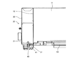
- FIG. 3 is a front view of the electric product unit 20 when the electric product box 40 of the indoor unit 1 of the air conditioner according to the embodiment is temporarily fixed to the electric product cabinet 30.
- FIG. 4 is a front view of the electric product unit 20 when the electric product box 40 of the indoor unit 1 of the air conditioner according to the embodiment is pulled out from the electric product cabinet 30.
- the electric product unit 20 has an electric product cabinet 30 and an electric product box 40.
- the electrical cabinet 30 is attached to the left side surface 12 of the indoor unit main body 10.
- the electrical product cabinet 30 houses the electrical product box 40 in which the electrical components of the indoor unit 1 are mounted.
- the entrance of the electric product box 40 to the electric product cabinet 30 is the lower surface of the electric product cabinet 30.
- a notch 31 is formed at the lower end of the front surface of the electrical cabinet 30.
- a protrusion 41 is formed at the lower part of the front surface of the electrical product box 40. The position where the protrusion 41 is formed may be lower than the central portion of the electrical component box 40. Further, the notch portion 31 may be the front surface, the side surface, or the like as long as it is formed on the surface of the electrical product cabinet 30. The protrusion 41 may be on the front surface, the side surface, or the like as long as it is formed on the surface of the electrical product box 40.
- the "surface” is a position where it is not blocked from being visually recognized by the operator by a wall or the like. However, the notch 31 and the protrusion 41 are formed on surfaces in the same direction.
- the stopper 21 is composed of the notch 31 and the protrusion 41.
- the stopper 21 temporarily fixes the electrical product cabinet 30 and the electrical product box 40.
- the front surface of the electric product cabinet 30 in which the notch 31 is formed and the front surface of the electric product box 40 in which the protrusion 41 is formed are perpendicular to the surface of the electric product box 40 which is the entrance to the electric product cabinet 30. It is a face.
- the electrical box 40 can be pulled out downward from the electrical cabinet 30.
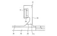
- FIG. 5 is an enlarged detailed view of the stopper 21 of the electrical component unit 20 of the indoor unit 1 of the air conditioner according to the embodiment.
- FIG. 6 is a diagram showing an electric product cabinet 30 and an electric product box 40 when the electric product unit 20 of the indoor unit 1 of the air conditioner according to the embodiment is temporarily fixed.
- FIG. 7 is a diagram showing an electric product cabinet 30 and an electric product box 40 when the electric product unit 20 of the indoor unit 1 of the air conditioner according to the embodiment is housed.
- a notch 31 is formed on the front surface 11 of the electrical cabinet 30.
- the peripheral edge of the notch 31 of the electrical cabinet 30 has a lateral portion 32 and a height direction portion 33.
- the lateral portion 32 forms a part of the peripheral edge extending in the lateral direction among the peripheral edges of the notch portion 31.
- the height direction portion 33 forms a part of the peripheral edge extending in the height direction among the peripheral edges of the notch portion 31.
- the corner of the lower end of the lateral portion 32 is taken to form an inclined portion 34.
- the inclined portion 34 is formed in a direction in which it is inclined with respect to the height direction portion 33 so that the inlet 31a formed below the notch portion 31 into which the protrusion 41 is inserted is narrowed upward.
- the protrusion 41 formed on the electric product box 40 is upward along the inclined portion 34 formed on the electric product cabinet 30. Move to. After that, as shown in FIG. 6, the protrusion 41 is supported and fixed to the lateral portion 32 formed in the electrical cabinet 30. As a result, the electric product box 40 is temporarily fixed to the electric product cabinet 30, and the electric product box 40 is prevented from falling. Further, since the inlet 31a of the notch portion 31 is formed so that the width becomes narrower toward the upper side, the protrusion 41 can be easily inserted.
- FIG. 8 is a view of the indoor unit of the air conditioner according to the embodiment when the electric component box 40 is pulled out from the open state of the panel cover 51 as viewed from below.
- the screw n1 is passed through the screw hole 42a formed in the electrical product box 40, and the screw n2 is passed through the screw hole 42b formed in the electrical product box 40 and fixed to the electrical product cabinet 30. ..
- the protrusions 41 are formed in the vicinity of the screw holes 42a at predetermined intervals. Further, the protrusion 41 is formed on the surface of the panel cover 51 opposite to the hinge 54. Therefore, the stopper 21 of the temporary fixing portion is easily visible. Further, the stopper 21 can easily release the temporary fixing of the electric product box 40.
- the electrical product box 40 can be pulled out from the electrical product cabinet 30. By opening the panel cover 51 during the installation work and the maintenance work at the installation location, the operator can pull out the electric component box 40 without removing the panel 50. The operator can perform operations such as operation and repair of the substrate 70 housed in the pulled-out electric product box 40.
- FIG. 9 is a diagram showing a modified example 1 of the lateral portion 32a of the indoor unit of the air conditioner according to the embodiment.
- a detachment prevention protrusion 35 projecting upward from the lateral portion 32a is formed.
- FIG. 10 is a diagram showing a modified example 2 of the lateral portion 32a of the indoor unit of the air conditioner according to the embodiment.
- the surface on which the protrusion 41 is hooked is formed as an inclined portion 36 for preventing disengagement from the lateral portion 32a.
- the detachment prevention inclined portion 36 is inclined so that the height on the inlet 31a side into which the protrusion 41 is inserted is high.
- notch 31 and protrusion 41 ⁇ Modification example of notch 31 and protrusion 41>
- the case where the notch 31 is formed in the electric product cabinet 30 and the protrusion 41 is formed in the electric product box 40 has been described, but the notch portion 31 is formed in the electric product box 40.
- the protrusion 41 may be formed in the electric product cabinet 30.
- the electric cabinet 30 is attached to one surface of the indoor unit main body 10.
- a protrusion 41 is formed on the surface of one of the electric product box 40 and the electric product cabinet 30.
- a notch 31 is formed on the other surface of the electric product box 40 and the electric product cabinet 30. Then, the protrusion 41 inserted into the notch 31 is supported by a part of the peripheral edge of the notch 31, and the electric product box 40 is fixed to the electric product cabinet 30.
- the electrical box 40 can be pulled out from the electrical cabinet 30.
- the protrusion 41 is formed on one surface of the electric product box 40 or the electric product cabinet 30, and the notch portion 31 is formed on the other surface of the electric product box 40 or the electric product cabinet 30.
- the fixed position and fixed structure of the product box 40 can be visually recognized. Further, when the protrusion 41 is removed from the notch, the electrical box 40 can be pulled out from the electrical cabinet 30. As a result, the efficiency of the installation work and the maintenance work of the electric component box 40 at the installation location of the indoor unit 1 of the air conditioner is improved.
- the electric product box 40 pulled out downward can be easily removed, and for example, the parts mounted on the electric product box 40 can be removed. In the event of a failure, parts can be easily replaced.
- the stopper 21 has a simple structure of the protrusion 41 and the notch 31, the electric product box 40 can be easily fixed to the electric product cabinet 30. Since the electric product box 40 is stably fixed at the position of the lateral portion 32 of the notch portion 31, it is possible to prevent the electric product box 40 from falling from the indoor unit 1.
- the protrusion 41 is formed in the vicinity of the screw hole 42a. This makes it easier to see the position and structure of the stopper 21.
- the detachment prevention protrusion 35 or the detachment prevention inclined portion 36 in the lateral direction portion 32a, it is possible to further suppress the protrusion 41 from coming off from the notch portion 31.
- the protrusion 41 of the embodiment is also referred to as a first protrusion, and the protrusion 35 for preventing disengagement is also referred to as a second protrusion.
- 1 Indoor unit 10 Indoor unit body, 11 Front, 12 Left side, 13 Right side, 20 Electrical unit, 21 Stopper, 30 Electrical cabinet, 31 Notch, 31a entrance, 32, 32a Horizontal part, 33 Height Directional part, 34 inclined part, 35 protruding part for prevention of detachment, 36 inclined part for prevention of detachment, 40 electric goods box, 41 protruding part, 42a, 42b screw hole, 50 panel, 51 panel cover, 52 suction port, 53 blow Outlet, 54 hinge, 60 refrigerant pipe inlet / outlet, 70 board, n1, n2 screws.
Landscapes
- Engineering & Computer Science (AREA)
- Chemical & Material Sciences (AREA)
- Combustion & Propulsion (AREA)
- Mechanical Engineering (AREA)
- General Engineering & Computer Science (AREA)
- Air Filters, Heat-Exchange Apparatuses, And Housings Of Air-Conditioning Units (AREA)
Priority Applications (2)
| Application Number | Priority Date | Filing Date | Title |
|---|---|---|---|
| JP2022504925A JP7378573B2 (ja) | 2020-03-06 | 2020-03-06 | 空気調和機の室内機 |
| PCT/JP2020/009745 WO2021176699A1 (ja) | 2020-03-06 | 2020-03-06 | 空気調和機の室内機 |
Applications Claiming Priority (1)
| Application Number | Priority Date | Filing Date | Title |
|---|---|---|---|
| PCT/JP2020/009745 WO2021176699A1 (ja) | 2020-03-06 | 2020-03-06 | 空気調和機の室内機 |
Publications (1)
| Publication Number | Publication Date |
|---|---|
| WO2021176699A1 true WO2021176699A1 (ja) | 2021-09-10 |
Family
ID=77614001
Family Applications (1)
| Application Number | Title | Priority Date | Filing Date |
|---|---|---|---|
| PCT/JP2020/009745 Ceased WO2021176699A1 (ja) | 2020-03-06 | 2020-03-06 | 空気調和機の室内機 |
Country Status (2)
| Country | Link |
|---|---|
| JP (1) | JP7378573B2 (https=) |
| WO (1) | WO2021176699A1 (https=) |
Citations (5)
| Publication number | Priority date | Publication date | Assignee | Title |
|---|---|---|---|---|
| JPS4618208Y1 (https=) * | 1968-10-11 | 1971-06-25 | ||
| JPH0277517U (https=) * | 1988-11-29 | 1990-06-14 | ||
| JPH0527525U (ja) * | 1991-09-24 | 1993-04-09 | 株式会社富士通ゼネラル | 空気調和機 |
| JPH0536212U (ja) * | 1991-10-15 | 1993-05-18 | 三菱電機株式会社 | 空気調和機の電気品箱 |
| WO2007090804A2 (en) * | 2006-02-07 | 2007-08-16 | Elicent Societa' Per Azioni | In-line centrifugal ventilator |
-
2020
- 2020-03-06 JP JP2022504925A patent/JP7378573B2/ja active Active
- 2020-03-06 WO PCT/JP2020/009745 patent/WO2021176699A1/ja not_active Ceased
Patent Citations (5)
| Publication number | Priority date | Publication date | Assignee | Title |
|---|---|---|---|---|
| JPS4618208Y1 (https=) * | 1968-10-11 | 1971-06-25 | ||
| JPH0277517U (https=) * | 1988-11-29 | 1990-06-14 | ||
| JPH0527525U (ja) * | 1991-09-24 | 1993-04-09 | 株式会社富士通ゼネラル | 空気調和機 |
| JPH0536212U (ja) * | 1991-10-15 | 1993-05-18 | 三菱電機株式会社 | 空気調和機の電気品箱 |
| WO2007090804A2 (en) * | 2006-02-07 | 2007-08-16 | Elicent Societa' Per Azioni | In-line centrifugal ventilator |
Also Published As
| Publication number | Publication date |
|---|---|
| JP7378573B2 (ja) | 2023-11-13 |
| JPWO2021176699A1 (https=) | 2021-09-10 |
Similar Documents
| Publication | Publication Date | Title |
|---|---|---|
| JP5669650B2 (ja) | 空気調和機の室外機 | |
| JP6678738B2 (ja) | 空気調和装置の室内機 | |
| JP2017516001A (ja) | 気流制御用ドアシステム | |
| US11143419B2 (en) | Air-conditioning apparatus | |
| EP3076095A1 (en) | Indoor unit | |
| JP3806879B2 (ja) | 空気調和機の室内機 | |
| US11421912B2 (en) | Packing system including packing material for air conditioner and air conditioner | |
| JP7138782B2 (ja) | 空気調和機の室外機 | |
| CN108826464A (zh) | 天花机 | |
| WO2021176699A1 (ja) | 空気調和機の室内機 | |
| US20140253268A1 (en) | Cover Assembly for Automatic Transfer Switch (ATS) | |
| CN110621942A (zh) | 空调机 | |
| JPH06284522A (ja) | 制御盤 | |
| JP2000249364A (ja) | ビルトイン型空気調和機 | |
| JPWO2019073547A1 (ja) | 空気調和機の室外機 | |
| JP2009030884A (ja) | 室外ユニット | |
| JP6785938B2 (ja) | 空気調和装置の室内機 | |
| JPWO2020170423A1 (ja) | 室内機および空気調和装置 | |
| JP6242169B2 (ja) | 制御盤及びポンプ装置 | |
| WO2020075243A1 (ja) | 空気調和機の室外機 | |
| CN115750454A (zh) | 一种风机安装结构和电气机柜 | |
| JP2000249362A (ja) | ビルトイン型空気調和機 | |
| CN100565022C (zh) | 空调的室内单元 | |
| JP2000249363A (ja) | ビルトイン型空気調和機 | |
| JPH0650574A (ja) | 熱交換ユニット |
Legal Events
| Date | Code | Title | Description |
|---|---|---|---|
| 121 | Ep: the epo has been informed by wipo that ep was designated in this application |
Ref document number: 20922873 Country of ref document: EP Kind code of ref document: A1 |
|
| ENP | Entry into the national phase |
Ref document number: 2022504925 Country of ref document: JP Kind code of ref document: A |
|
| NENP | Non-entry into the national phase |
Ref country code: DE |
|
| 122 | Ep: pct application non-entry in european phase |
Ref document number: 20922873 Country of ref document: EP Kind code of ref document: A1 |