WO2021176511A1 - 内視鏡汚れ検知装置、内視鏡リプロセッサ及び内視鏡汚れ検知方法 - Google Patents
内視鏡汚れ検知装置、内視鏡リプロセッサ及び内視鏡汚れ検知方法 Download PDFInfo
- Publication number
- WO2021176511A1 WO2021176511A1 PCT/JP2020/008664 JP2020008664W WO2021176511A1 WO 2021176511 A1 WO2021176511 A1 WO 2021176511A1 JP 2020008664 W JP2020008664 W JP 2020008664W WO 2021176511 A1 WO2021176511 A1 WO 2021176511A1
- Authority
- WO
- WIPO (PCT)
- Prior art keywords
- endoscope
- image
- unit
- detection device
- light
- Prior art date
- Legal status (The legal status is an assumption and is not a legal conclusion. Google has not performed a legal analysis and makes no representation as to the accuracy of the status listed.)
- Ceased
Links
Images






Classifications
-
- G—PHYSICS
- G01—MEASURING; TESTING
- G01N—INVESTIGATING OR ANALYSING MATERIALS BY DETERMINING THEIR CHEMICAL OR PHYSICAL PROPERTIES
- G01N21/00—Investigating or analysing materials by the use of optical means, i.e. using sub-millimetre waves, infrared, visible or ultraviolet light
- G01N21/84—Systems specially adapted for particular applications
- G01N21/88—Investigating the presence of flaws or contamination
- G01N21/94—Investigating contamination, e.g. dust
-
- G—PHYSICS
- G01—MEASURING; TESTING
- G01N—INVESTIGATING OR ANALYSING MATERIALS BY DETERMINING THEIR CHEMICAL OR PHYSICAL PROPERTIES
- G01N21/00—Investigating or analysing materials by the use of optical means, i.e. using sub-millimetre waves, infrared, visible or ultraviolet light
- G01N21/62—Systems in which the material investigated is excited whereby it emits light or causes a change in wavelength of the incident light
-
- G—PHYSICS
- G01—MEASURING; TESTING
- G01N—INVESTIGATING OR ANALYSING MATERIALS BY DETERMINING THEIR CHEMICAL OR PHYSICAL PROPERTIES
- G01N21/00—Investigating or analysing materials by the use of optical means, i.e. using sub-millimetre waves, infrared, visible or ultraviolet light
- G01N21/62—Systems in which the material investigated is excited whereby it emits light or causes a change in wavelength of the incident light
- G01N21/63—Systems in which the material investigated is excited whereby it emits light or causes a change in wavelength of the incident light optically excited
- G01N21/64—Fluorescence; Phosphorescence
- G01N21/6486—Measuring fluorescence of biological material, e.g. DNA, RNA, cells
-
- G—PHYSICS
- G01—MEASURING; TESTING
- G01N—INVESTIGATING OR ANALYSING MATERIALS BY DETERMINING THEIR CHEMICAL OR PHYSICAL PROPERTIES
- G01N21/00—Investigating or analysing materials by the use of optical means, i.e. using sub-millimetre waves, infrared, visible or ultraviolet light
- G01N21/84—Systems specially adapted for particular applications
- G01N21/88—Investigating the presence of flaws or contamination
-
- G—PHYSICS
- G01—MEASURING; TESTING
- G01N—INVESTIGATING OR ANALYSING MATERIALS BY DETERMINING THEIR CHEMICAL OR PHYSICAL PROPERTIES
- G01N21/00—Investigating or analysing materials by the use of optical means, i.e. using sub-millimetre waves, infrared, visible or ultraviolet light
- G01N21/84—Systems specially adapted for particular applications
- G01N21/88—Investigating the presence of flaws or contamination
- G01N21/8806—Specially adapted optical and illumination features
-
- A—HUMAN NECESSITIES
- A61—MEDICAL OR VETERINARY SCIENCE; HYGIENE
- A61B—DIAGNOSIS; SURGERY; IDENTIFICATION
- A61B1/00—Instruments for performing medical examinations of the interior of cavities or tubes of the body by visual or photographical inspection, e.g. endoscopes; Illuminating arrangements therefor
-
- A—HUMAN NECESSITIES
- A61—MEDICAL OR VETERINARY SCIENCE; HYGIENE
- A61B—DIAGNOSIS; SURGERY; IDENTIFICATION
- A61B1/00—Instruments for performing medical examinations of the interior of cavities or tubes of the body by visual or photographical inspection, e.g. endoscopes; Illuminating arrangements therefor
- A61B1/12—Instruments for performing medical examinations of the interior of cavities or tubes of the body by visual or photographical inspection, e.g. endoscopes; Illuminating arrangements therefor with cooling or rinsing arrangements
- A61B1/121—Instruments for performing medical examinations of the interior of cavities or tubes of the body by visual or photographical inspection, e.g. endoscopes; Illuminating arrangements therefor with cooling or rinsing arrangements provided with means for cleaning post-use
Definitions
- the present invention relates to an endoscope stain detection device for detecting stains on an endoscope, an endoscope reprocessor, and an endoscope stain detection method.
- the endoscope is washed after use to prevent infectious diseases. It is not easy for the inspector to visually confirm or judge whether or not dirt remains on the surface of the insertion portion of the endoscope after cleaning. Therefore, various proposals have been made for a cleaning device that detects the state of the surface of the insertion portion of the endoscope after cleaning, in other words, the cleaning state.
- Japanese Patent Application Laid-Open No. 10-276977 states that the outer surface of an endoscope is dyed with a dye solution, and after cleaning, it is detected whether the dye solution adheres to the outer surface of the endoscope.
- a cleaning device for an endoscope that detects the degree of cleaning of the outer surface of the endoscope is disclosed.
- an object of the present invention is to provide an endoscope stain detection device, an endoscope reprocessor, and an endoscope stain detection method that detect stains on an endoscope without the need for complicated work.
- the endoscope stain detection device includes an irradiation unit that irradiates the endoscope with light of a specific wavelength, a light receiving unit that receives fluorescence emitted by dirt adhering to the surface of the endoscope, and a light receiving unit.
- An image forming unit that forms a first image from the fluorescence, an image processing unit that performs image processing on the first image to form a second image that emphasizes a portion contaminated by the filth, and the second image.
- the endoscope reprocessor of one aspect of the present invention includes an endoscope stain detection device of one aspect of the present invention, a regeneration processing unit that performs regeneration processing on the endoscope, and the endoscope from the second image. It has a pollution degree determination unit for determining the degree of contamination and a control unit for controlling the execution of the regeneration process, and the control unit executes the first program when the pollution degree is less than a predetermined value. When the degree of contamination is equal to or higher than the predetermined value, the second program having a higher regeneration processing level than the first program is executed.
- the method for detecting endoscopic stains includes a step of irradiating the endoscope with light of a specific wavelength, a step of receiving fluorescence emitted by dirt adhering to the surface of the endoscope, and the received fluorescence.
- the first image is formed from the above, and the first image is subjected to image processing to form a second image in which the portion contaminated by the filth is emphasized.
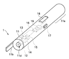
- FIG. 1 is a perspective view of an endoscope stain detection device according to the first embodiment.
- the endoscope dirt detection device (hereinafter abbreviated as a dirt detection device) 1 is a device that detects the dirt on the endoscope after use, and is used by a person who confirms the dirt on the endoscope (hereinafter referred to as a user). , A handy type that can be grasped and used by hand.
- the dirt detection device 1 has an objective optical system 12, a light source 13, an optical divider 14, an image sensor 15, and a control board 16 in a housing 11. Although the housing 11 has a cylindrical shape in FIG.
- the present invention is not limited to this, and the housing 11 may have a shape that is easy for the user to grasp by hand.
- the grip portion 11a is a base end side portion of the housing 11.
- An operation button 17 and a display 18 as an output unit are provided on the outer surface of the housing 11.
- the material of the housing 11 is not particularly limited, but for example, resin, metal, or ceramics can be used.
- the tip of the housing 11 is provided with an extending portion 11b that projects in the tip direction on the longitudinal axis of the housing 11.
- the extending portion 11b extends from the tip end portion of the housing 11 by a predetermined length.
- the front end surface 11c of the housing 11 has an observation window 11d which is an opening.
- An image pickup device 15 is arranged behind the observation window 11d.
- the housing 11 may have a positioning member for forming a focused subject image on the image pickup surface of the image pickup element 15. As the positioning member, the extension portion 11b illustrated in FIGS. 1 and 5 can be used.
- the extension portion 11b may be detachable, or may be replaced with an appropriate shape from a plurality of types of extension portions 11b according to the observation target and the purpose. Further, the dirt detection device 1 may have a sighting device or an autofocus function instead of the positioning member.
- the objective optical system 12 is arranged behind the observation window 11d. As shown in FIG. 5, which will be described later, for example, the user places the tip DE of the insertion portion on the bottom surface S of the processing tank of the endoscope reprocessor and the tip of the extension portion 11b against the bottom surface S of the processing tank for observation. When the window 11d is directed toward the tip DE of the insertion portion, the light from the tip that has passed through the objective optical system 12 is applied to the tip DE. Due to the fluorescence from the tip DE, a fluorescence image of the tip DE is formed on the image pickup surface of the image sensor 15.
- the extending portion 11b is a member that constantly adjusts the distance between the subject and the observation window 11d for forming a subject image on the image pickup surface of the image pickup device 15.
- the extension portion 11b is a distance adjusting member that constantly adjusts the distance between the observation window 11d and the endoscope.
- the light source 13 is a mercury lamp or the like.
- the light of the light source 13 is supplied to the light divider 14 by the light irradiation optical system 13a.
- the light source 13 is provided in the housing 11, the light source 13 is provided in an external device, and the light of the light source 13 is guided to the optical divider 14 in the housing 11 by an optical fiber or the like (not shown). You may do so.
- the optical divider 14 is arranged on the proximal end side of the objective optical system 12. As will be described later, the optical divider 14 irradiates the filth adhering to the surface of the endoscope (specifically, the surface of the tip of the insertion portion) with a predetermined wavelength, and emits the excitation light of the filth to the image pickup device 15. Includes a plurality of optical elements that divide the light so as to irradiate the light.
- the image sensor 15 is a CMOS area image sensor or the like.
- the image sensor 15 as a light receiving unit is arranged on the proximal end side of the optical divider 14.
- the control board 16 is a control device having a processor 19 and various circuits.
- the processor 19 drives the light source 13 and the image pickup element 15 in response to the button operation, receives the image pickup signal, and performs predetermined image processing. Further, the processor 19 generates an output signal according to the result of predetermined image processing and outputs the output signal to the display 18.
- the configuration of the processor 19 will be described later.
- FIG. 2 is a diagram showing an optical path from a light source to a subject and a configuration of an imaging optical system that receives fluorescence from the subject.
- the light from the light source 13 is emitted to the excitation filter 21 through the light irradiation optical system 13a.
- the light that has passed through the excitation filter 21 enters the optical divider 14.
- the optical divider 14 has a dichroic mirror 22.
- the dichroic mirror 22 is arranged in the optical divider 14 so as to reflect the light from the excitation filter 21 toward the objective optical system 12.
- the dichroic mirror 22 is arranged so that the light that has passed through the excitation filter 21 is bent at a right angle and emitted to the objective optical system 12.
- the light incident on the objective optical system 12 is emitted from the observation window 11d and irradiates the subject. Therefore, the light source 13, the excitation filter 21, and the dichroic mirror 22 constitute a light irradiating unit or a light irradiator that irradiates the endoscope with light having a specific wavelength. As will be described later, the light radiated to the subject functions as excitation light for causing fluorescence in the subject, and the excitation light is emitted from the subject and incident on the objective optical system 12 through the observation window 11.
- each optical element biological tissue, which is the main component of filth, is used as the excitation light.
- the living tissue varies depending on the insertion destination of the endoscope and the medical condition of the subject, and examples thereof include red blood cells or bile.
- red blood cells or bile In the case of erythrocytes, the wavelength at which hemoglobin contained in erythrocytes autofluorescent is used.
- bile the wavelength at which heme contained in bile or heme metabolites such as bilirubin or bile pigment autofluoresce is used. That is, the present embodiment detects the autofluorescence of the filth-containing material adhering to the outer surface of the endoscope after use. In other words, the stains are made to shine without the use of fluorescent markers. Therefore, each filter has the following characteristics.
- FIG. 3 is a table showing the wavelength characteristics of the excitation filter 21, the dichroic mirror 22, and the absorption filter 23.
- the excitation filter 21 has a property of transmitting light having a wavelength of 360 nm to 370 nm to generate excitation light
- the dichroic mirror 22 has the excitation light generated by the excitation filter.
- the absorption filter 23 has a property of reflecting light having a wavelength of less than 400 nm and transmitting light having a wavelength of 400 nm or more, and the absorption filter 23 transmits only light having a wavelength of 420 nm to 460 nm among self-fluorescence emitted from filth.
- each optical element has optical characteristics, for example, an illumination light of 365 nm is irradiated as excitation light, and the image pickup element 15 can capture an image of self-fluorescence of the subject.
- the specific wavelength of the light irradiating the endoscope is a wavelength of 360 nm or more.
- the excitation filter 21 has a property of transmitting light having a wavelength of 460 nm to 495 nm to generate excitation light
- the dichroic mirror 22 has the excitation light generated by the excitation filter.
- the absorption filter 23 has a property of reflecting light having a wavelength of less than 505 nm and transmitting light having a wavelength of 505 nm or more, and the absorption filter 23 transmits only light having a wavelength of 510 nm to 550 nm among self-fluorescence emitted from filth.
- each optical element irradiates illumination light of, for example, 490 nm as excitation light, and the image pickup element 15 can capture an image of self-fluorescence of the subject.
- the specific wavelength of the light irradiating the endoscope is a wavelength of 460 nm or more
- the excitation filter 21 transmits light having a wavelength of 460 nm or more
- the dichroic mirror 22 reflects light having a wavelength of less than 505 nm.
- light having a wavelength of 505 nm or more is transmitted, and the absorption filter 23 transmits light having a wavelength of 510 nm to 550 nm.
- the excitation filter 21 has a property of transmitting light having a wavelength of 530 nm to 550 nm to generate excitation light
- the dichroic mirror 22 has the property of generating excitation light.
- the absorption filter 23 has the property of reflecting light having a wavelength of less than 570 nm and transmitting light having a wavelength of 570 nm or more, and the absorption filter 23 transmits only light having a wavelength of 575 nm to 625 nm among self-fluorescence emitted from filth.
- each optical element irradiates illumination light of, for example, 546 nm as excitation light, and the image pickup element 15 can capture an image of self-fluorescence of the subject.
- the specific wavelength of the light irradiating the endoscope is a wavelength of 530 nm or more
- the excitation filter 21 transmits light having a wavelength of 530 nm or more
- the dichroic mirror 22 reflects light having a wavelength of less than 570 nm.
- the absorption filter 23 transmits light having a wavelength of 575 nm to 625 nm.
- hemoglobin and bile cause autofluorescence when irradiated with light having a specific wavelength or higher as excitation light.
- the specific wavelength preferably includes excitation light having a wavelength of 360 nm or more, and more preferably includes excitation light having a wavelength of 460 nm or more.
- light having a wavelength of 490 nm or 546 nm is contained, hemoglobin and bile are strongly likely to emit autofluorescence, that is, are easily excited, and the image sensor 15 is capable of identifying fine stains.
- Quartz glass may be used instead of the dichroic mirror 22. Quartz glass reflects excitation light and transmits light having a wavelength of 400 nm or more to 700 nm or less, so that a wider range of wavelengths can be applied to the image pickup device 15.
- FIG. 4 is a configuration diagram including a functional block of the processor of the endoscope stain detection device according to the present embodiment. Note that FIG. 4 shows only the portion related to the processing of the image pickup signal from the image pickup device 15.
- the processor 19 includes an image forming unit 19a, an image processing unit 19b, and an output processing unit 19c.
- the processor 19 includes a central processing unit (CPU), a ROM, a RAM, and the like, and realizes the functions of each part such as the image forming unit 19a by reading a software program stored in the ROM, expanding the software program into the RAM, and executing the program. do.
- CPU central processing unit
- ROM read-only memory
- RAM random access memory
- the processor 19 may be configured by a semiconductor device such as an FPGA (Field Programmable Gate Array), an electronic circuit, or the like, and the functions of each part such as the image forming unit 19a may be realized by the circuit.
- a semiconductor device such as an FPGA (Field Programmable Gate Array), an electronic circuit, or the like, and the functions of each part such as the image forming unit 19a may be realized by the circuit.
- the image pickup signal acquisition unit 16a is an input circuit that acquires an image pickup signal from the image pickup element 15 and outputs the image pickup signal to the processor 19, and is included in the control board 16.
- the image forming unit 19a generates or forms a fluorescence image from the subject formed on the image pickup surface of the image pickup device 15 based on the image pickup signal from the image pickup signal acquisition unit 16a. That is, the image forming unit 19a forms a fluorescence image from the received fluorescence.
- the image processing unit 19b performs predetermined image processing, here binarization processing, on the fluorescent image formed in the image forming unit 19a to generate a binarized image.
- the binarization process compares the set threshold value TH with the brightness value of each pixel, and generates a fluorescence image of only the pixels having the threshold value TH or higher from the image formed by the image forming unit 19a.
- the binarized image is an image showing a portion contaminated by filth.
- the contaminated area contains blood or bile. Therefore, the image processing unit 19b performs image processing on the fluorescent image to form an image in which the contaminated portion due to the filth is emphasized.
- the output processing unit 19c includes a circuit that generates an output signal IS based on the binarized image from the image processing unit 19b and outputs the output signal IS to the display 18. As will be described later, the output processing unit 19c may output the image data of the binarized image. Therefore, the image processing unit 19b and the output processing unit 19c form an output unit that outputs an image in which the contaminated portion is emphasized.
- the drive circuit for driving the image sensor 15 provided on the control board 16 operates to generate a drive signal for driving the image sensor 15.
- the image pickup signal acquisition unit 16a acquires an image pickup signal from the image pickup element 15.
- the image pickup signal acquisition unit 16a receives the image pickup signal from the image pickup device 15, the image pickup signal acquisition unit 16a supplies the image pickup signal to the image formation unit 19a.
- the image processing unit 19b performs binarization processing on the image pickup signal, and outputs the image signal of the binarized image to the output processing unit 19c.
- the output processing unit 19c determines the degree of contamination of the endoscope based on the binarized image, generates an output signal IS indicating the degree of contamination, and outputs the output signal IS to the display 18. That is, the output processing unit 19c constitutes a contamination degree determination unit that determines the contamination degree of the endoscope from the binarized image.
- the output signal IS is a signal for displaying a message on the display 18, but is a signal for outputting a predetermined sound by a sound output device such as a buzzer instead of the display 18. It may be.
- the output signal IS as a dirt detection result signal is, for example, a signal indicating the presence or absence of dirt or the degree of dirt (hereinafter, also referred to as the degree of pollution).
- the output signal IS has a small degree of contamination based on a message indicating the presence or absence of pixels whose luminance value is equal to or greater than a predetermined threshold value, or the ratio of the number of pixels whose luminance value is equal to or greater than a predetermined threshold value to the total number of pixels. It is a signal indicating an index such as medium or large.
- the predetermined threshold value TH is 70.
- the output processing unit 19c generates a display message such as "no terrible stains" and displays it on the display 18.
- the output processing unit 19c generates a display message such as "dirty.
- the degree of stain is large” and displays the display 18 Display in.
- the “degree of stain” is set to “small” and the brightness value is predetermined with respect to the total number of pixels.
- the ratio of the number of pixels of the threshold value XX or more is 0.3 or more, the “degree of dirt” is set to “large”.
- the number of pixels whose luminance value is equal to or greater than a predetermined threshold value is proportional to the area in the fluorescence image.
- FIG. 5 is a diagram for explaining the dirt detection device 1 when detecting dirt on the tip of the insertion portion of the endoscope and the arrangement of the tip.
- K indicates a riser provided in the tip portion DE.
- the user places the tip DE on the bottom S of the processing tank of the endoscope reprocessor, and hits the tip of the extension 11b against the bottom S so that the tip DE is within the imaging range R of the observation window 11d. Touch.
- excitation light having a predetermined wavelength from the light source 13 is emitted from the observation window 11d. If filth containing hemoglobin is attached to the surface of the tip DE, fluorescence is generated from the filth by the excitation light that hits the tip DE.
- the image processing unit 19b generates a binarized image from the fluorescent image. Based on the binarized fluorescence image, the output processing unit 19c generates an output signal IS and outputs it to the display 18.
- the user can set the reproduction processing time in the reproduction processing by the endoscope reprocessor by observing the presence or absence of dirt or the degree of dirt on the endoscope displayed on the display unit 18. For example, if the dirt is not severe, the user sets the reproduction processing time to a normal set time, and if the dirt is severe, the user sets the reproduction processing time to be longer than the normal set time.
- the user can also add special cleaning such as gas-liquid two-phase flow to the cleaning menu and change the type of detergent to one containing enzymes if it is very dirty.
- the presence or absence of stains or the degree of stains is output based on the image obtained by the binarization process and displayed on the display 18, but as described above, the brightness value is equal to or higher than the threshold value TH.
- the degree of dirt may be output according to the level of the brightness value of the pixel.
- the image processing unit 19b generates an image having a brightness value of the threshold value TH or higher, and determines the degree of contamination as “large”, “medium”, or “small” according to the level of the brightness value of each pixel. That is, the degree of contamination is output in consideration of not only the presence / absence of pixels whose brightness value in the binarized image is equal to or higher than the threshold value and the number of pixels, but also the brightness value level of each pixel included in the fluorescent image. It may be.
- the concentration of hemoglobin and the like contained in the dirt increases, so that the degree of dirt can be determined according to the brightness value level.
- the degree of contamination is "large”, depending on the number of pixels in the binarized image whose brightness value is not the threshold TH or higher, but the number of pixels whose brightness value is the threshold YH or higher in the binarized image. You may decide “medium” and "small”.
- the number of lumps of pixels having a threshold TH or higher in the binarized image is also taken into consideration, and the degree of contamination is "large”. , “Medium”, “Small” may be determined.
- the inspection result is displayed as a message on the display 18 provided in the dirt detection device 1, but as shown by the dotted line in FIG. 3, the transmitter 18a is provided in the dirt detection device 1 and output.
- the signal IS may be transmitted to an external device through a transmitter 18a that transmits by wire or wirelessly.
- the transmitted output signal IS message is received from the transmitter 18a by a personal computer or the like (hereinafter, abbreviated as PC) which is an external device, and is displayed on the monitor of the PC. Therefore, the user can know the degree of dirtiness of the endoscope from the message displayed on the monitor and set the cleaning time of the endoscope reprocessor and the like.
- the external device may be an endoscope reprocessor, and in that case, the user can set the cleaning time of the endoscope reprocessor by seeing the message displayed on the display of the endoscope reprocessor. can.
- the endoscope reprocessor may automatically set the cleaning time or the like according to the received output signal IS.
- the output processing unit 19c generates a message as an output signal IS from the binarized image, but the stain detection device 1 transfers the image data of the binarized image to an external device, for example, a PC.
- the data may be transmitted and the binarized image as the output signal IS may be displayed on the monitor as an image of a predetermined color, for example, a red image in the external device. That is, the image processing unit 19c emphasizes the contaminated portion by the binarization process, and in the binarization process, the pixels whose brightness value is equal to or higher than the predetermined threshold value are displayed in the first color (for example, red), and the brightness is increased.
- the output processing unit 19c constitutes an output unit that outputs the image data of the binarized image to the external device through the transmitter 18a.
- the user can determine whether or not the endoscope is dirty and the degree of contamination by looking at the binarized image displayed on the monitor.
- the user sets the processing time of the reproduction process by the endoscope reprocessor according to the presence or absence of dirt on the endoscope and the degree of contamination.
- an endoscope stain detection device As described above, according to the above-described embodiment, an endoscope stain detection device, an endoscope reprocessor, and an endoscope stain detection method for detecting stains on an endoscope, which do not require complicated work, are provided. Can be provided.
- the tip DE of the insertion portion of the endoscope may have a riser K that can rotate about an axis in a predetermined manner, and the tip DE has a complicated shape and a recess.
- the riser K is used to change the orientation of forceps or the like. According to the dirt detection device 1 of the above-described embodiment, the user can easily confirm the presence or absence or degree of dirt on the tip portion DE having a complicated shape.
- the dirt detection device 1 of the above-described embodiment has a stick shape, the user excites the dirt detection device 1 at a desired position in the insertion portion without contacting the unsterilized endoscope. You can check the dirt on the desired part by shining light on it.
- the user can check the dirt on the insertion portion of the endoscope without touching the endoscope.
- the image processing unit 19b generates a binarized image by the binarization process
- the output processing unit 19c outputs an output signal IS based on the binarized image.
- a reasoning unit using deep learning may be provided in 19, and the presence or absence of dirt or the like may be inferred by the reasoning unit.
- FIG. 6 is a configuration diagram including a functional block of the processor of the endoscope stain detection device according to this modification.
- an inference unit 19d is provided between the image processing unit 19b and the output processing unit 19c.
- the inference unit 19d performs inference processing using an inference model using deep learning.
- FIG. 7 is a diagram showing a configuration example of the neural network included in the inference unit 19d.
- the inference model is generated using the neural network shown in FIG.
- the neural network has an input layer 31, a hidden layer 32, and an output layer 33.
- the input layer 31 has a plurality of input units 31a for the number of pixels for inputting the image data G1 from the image forming unit 19a and the image data G2 from the image processing unit 19b.
- the hidden layer 32 includes a plurality of nodes.
- the output layer 33 has four output units 33a, the first output unit of the four output units has an output D1 with a degree of dirt "large", and the second output unit has a degree of dirt "small”.
- the third output unit is the dirty “yes” output D3, and the fourth output unit is the dirty “no” output D4.
- Image data G1 and G2 and four outputs D1 to D4 as label data are used as teacher data, and a large amount of teacher data is given to the neural network to provide values such as connections and coefficients between a plurality of nodes in the hidden layer 32.
- a training model of a neural network is generated by training.
- the neural network is a convolutional neural network (Convolutional Neural Networks).
- the inference unit 19d uses the inference model generated as described above to generate the outputs of the outputs D1 to D4 from the two input image data. That is, the inference unit 19d infers the presence or absence of contamination or the degree of contamination by the filth adhering to the tip portion DE by using the inference model created by using the image data G1 and G2.
- the output layer 33 may output image data of a binarized image indicating a dirty area.
- FIG. 8 is a diagram showing a configuration example of another neural network related to a modified example of the inference unit 19d.
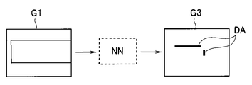
- FIG. 9 is a diagram for explaining that the neural network outputs image data indicating a dirty area from the input image data.
- the image data G1 from the image forming unit 19a is input to the input layer 31, and the output layer 33 outputs the image data G3 for displaying the image including the dirt region DA based on the image data G1.
- the image data G1 as the teacher data and the image data G3 of the binarized image including the dirty area as the label data a large amount of teacher data is given to the neural network to connect between a plurality of nodes of the hidden layer 32 and to connect the hidden layer 32.
- a training model of a neural network is generated by training a value such as a coefficient. Therefore, in this modification, the inference unit 19d is used instead of the image processing unit 19b, and the output of the image forming unit 19a is supplied to the inference unit 19d.
- the inference unit 19d constitutes an image processing unit that forms an image emphasizing a portion contaminated by filth.
- the inference unit 19d infers and generates an image showing the region of the contaminated portion by using the inference model created by using the image data G1.
- the output processing unit 19c outputs image data of an image indicating the region of the contaminated portion inferred by the inference unit 19d.
- the image data G1 by giving the image data G1, the image data of the image including the inferred dirt region DA is output from the inference unit 19d.
- the dirt detection device of the first embodiment has a stick shape, while the dirt detection device of the second embodiment has a dome shape.
- FIG. 10 and 11 are perspective views of the dirt detection device 1A of the second embodiment.
- FIG. 10 is a perspective view of the dirt detection device 1A according to the second embodiment as viewed from the gripping portion side.
- FIG. 11 is a perspective view of the cover of the dirt detection device 1A according to the second embodiment as viewed from the bottom surface side.
- the dirt detection device 1A has a hemispherical cover 41 having a space inside and a grip portion 42.
- the grip portion 42 is provided with an operation button 17 and a display 18.
- a light source 13, a light irradiation optical system 13a, an optical divider 14, an objective optical system 12, an excitation filter 21, a dichroic mirror 22, an absorption filter 23, an image pickup element 15, and a control board 16 are built in the space inside the grip portion 42. ing.
- the detection unit 43 provided on the grip portion 42 is shown by a alternate long and short dash line.
- the detection unit 43 includes a light source 13, a light irradiation optical system 13a, an optical divider 14, an objective optical system 12, an excitation filter 21, a dichroic mirror 22, an absorption filter 23, an image sensor 15, and a control substrate 16.
- a transmitter 18a which is a wireless transmitter, may be provided in the grip portion 42.
- a notch 41a is formed in a part of the cover 41.
- the notch portion 41a is an avoidance portion for preventing the outer peripheral portion of the insertion portion IP from colliding with the cover 41 when the cover 41 is put on the tip portion DE of the insertion portion of the endoscope. be.
- An observation window 11d is provided at the apex portion inside the cover 41.
- the objective optical system 12 is arranged behind the observation window 11d, and the objective optical system 12 is arranged so that the focal point of the objective optical system 12 is substantially located on the virtual plane P including the edge portion 41b of the hemispherical cover 41. Is configured. Therefore, as will be described later, when the insertion portion IP is fitted into the notch portion 41a and the tip portion DE is positioned below the observation window 11d, the tip portion DE is placed on the image pickup surface of the image sensor 15. Fluorescent image is formed.
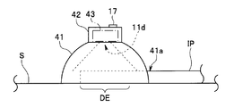
- FIG. 12 is a diagram for explaining how to use the dirt detection device 1A of the second embodiment.
- the user applies the circular edge 41b of the cover 41 to, for example, the sink S for bedside cleaning or the bottom surface S of the processing tank of the endoscope reprocessor, and inserts the endoscope into the notch 41a.
- the cover 41 functions in the same manner as a simple dark room, and when the operation button 17 is operated, the light from the light source 13 is irradiated to the tip DE as excitation light.
- the fluorescence from the filth on the tip DE is imaged on the image pickup surface of the image pickup device 15.
- the output processing unit 19c outputs the output signal IS to the display 18 from the binarized image generated by the image processing unit 19b.
- the output processing unit 19c may transmit the output signal IS from the transmitter 18a to the external device.
- the output signal IS is transmitted to the PC, and a message is displayed on the monitor of the PC.
- the output signal IS is transmitted to the endoscope reprocessor, and the cleaning time and the like are automatically set according to the output signal IS.
- the image data of the fluorescent image of the binarized image is transmitted as the output signal IS, and the processor 19 of the detection unit 43 is used.
- the inference unit 19d that makes an inference using an inference model using deep learning may be provided.
- the dirt detection device of the first embodiment has a stick shape, while the dirt detection device of the second embodiment has a book shape.
- FIG. 13 is a perspective view of the dirt detection device 1B according to the third embodiment.
- FIG. 14 is a side view of the dirt detection device 1B according to the third embodiment.
- FIG. 13 is a perspective view of the dirt detection device 1B with the lid open.
- FIG. 14 shows a state in which the tip end portion of the insertion portion to be inspected is set in the dirt detection device 1B.
- the dirt detection device 1B has a stage 51 for setting the tip DE of the insertion portion IP and a lid 52.
- the stage 51 has a plate-shaped rectangular parallelepiped shape, and an elongated groove 51a is formed on the upper surface thereof.
- a fixing groove 51b for fixing the insertion portion IP is formed along the longitudinal direction of the groove portion 51a.
- the stage 51 and the lid 52 can be opened and closed with respect to the stage 51 by two hinge members 53.
- the lid 52 also has a plate-shaped rectangular parallelepiped shape, and an observation window 11d is formed on the lower surface.
- the objective optical system 12 On the rear side of the observation window 11d, the objective optical system 12, the light source 13, the light irradiation optical system 13a, the optical divider 14, the objective optical system 12, the excitation filter 21, the dichroic mirror 22, and the absorption described in the first embodiment.
- a filter 23, an image sensor 15, a control board 16, and a transmitter 18a are built-in.
- the detection unit 43 provided on the lid 52 is shown by a chain double-dashed line.
- the detection unit 43 includes an objective optical system 12, a light source 13, a light irradiation optical system 13a, an optical divider 14, an objective optical system 12, an excitation filter 21, a dichroic mirror 22, an absorption filter 23, an image sensor 15, and a control substrate 16. .. Further, a transmitter 18a, which is a wireless transmitter, may be provided in the lid 52.
- an operation button 17 and a display 18 are provided on the upper surface of the lid 52.
- the lid 52 As shown in FIG. 14, when the user arranges the fixing groove 51b of the stage 51 so that the tip DE of the insertion portion IP of the endoscope fits, and the lid 52 is closed with respect to the stage 51, the lid 52 The covered groove 51a functions as a simple dark room, and can prevent outside light from entering the observation window 11d.
- the operation button 17 When the operation button 17 is operated in this state, the light from the light source 13 is irradiated to the tip DE as excitation light from the observation window 11d.
- the endoscope used for the groove 51a is placed, but if the lid 52 is opened, the user can easily clean the groove 51a.
- the tip portion DE in the longitudinal direction of the insertion portion IP can be arranged at an appropriate position. That is, the protrusion 51c makes it easier for the user to position the insertion portion IP.
- the fluorescence from the tip DE is imaged on the image pickup surface of the image pickup device 15.
- the output processing unit 19c generates an output signal IS based on the binarized image generated by the image processing unit 19b and outputs the output signal IS to the display 18.
- the endoscope as the subject and the irradiation unit or the light receiving portion are used so that the fluorescence image is appropriately formed on the image pickup surface of the image pickup device 15 according to the difference in the outer diameters of the insertion portion IP and the tip portion DE.
- It may have a distance adjustment mechanism for adjusting the imaging distance between the unit and the unit.
- the distance adjusting mechanism 54 as the distance adjusting unit automatically or manually attaches the image sensor 15 which is at least one lens or the light receiving unit of the objective optical system 12 along the optical axis direction of the objective optical system 12. Move.
- the distance adjusting mechanism 54 can be configured by, for example, a motor, a gear, a rack and pinion mechanism, or the like.
- the lens or the like moves when the user operates an operation switch (not shown).
- the distance to the tip DE is measured by a distance sensor (not shown), and the lens or the like moves based on the measured distance.
- the output processing unit 19c may transmit the output signal IS from the transmitter 18a to the external device.
- the output signal IS is transmitted to the PC, and a message is displayed on the monitor of the PC.
- the output signal IS is transmitted to the endoscope reprocessor, and the cleaning time and the like are automatically set according to the output signal IS.
- the image data of the fluorescent image is transmitted as the output signal IS, and the processor 19 of the detection unit 43 performs deep learning. Inference may be performed using the inference model used.
- the dirt detection device of the first embodiment has a stick shape, while the dirt detection device of the fourth embodiment has a box shape.
- FIG. 15 is a perspective view of the dirt detection device 1C according to the fourth embodiment.
- the dirt detection device 1C has a rectangular parallelepiped housing 61, an opening 61a formed on one side surface of the housing 61, an operation button 17 provided on the upper surface of the housing 61, and a display 18.
- the dirt detection device 1C has a built-in tubular member 62 that communicates with the opening 61a.
- the tubular member 62 has an inner diameter that allows the tip DE of the insertion portion IP to be inserted in a loosely fitted state, and has a bottom portion 62a.
- the tip DE of the insertion portion IP can be inserted into the inside of the tubular member 62 through the opening 61a.
- the tubular member 62 has an observation window 11d which is an opening on the inner peripheral surface thereof.
- the observation window 11d is provided at a position where the tip DE can be imaged by the image sensor 15 when the insertion portion IP is inserted into the tubular member 62 and the tip DE hits the bottom 62a of the tubular member 62. Has been done.
- the tip DE of the insertion portion IP of the endoscope As shown in FIG. 15, when the user inserts the tip DE of the insertion portion IP of the endoscope into the inside of the tubular member 62 from the opening 61a and operates the operation button 17, the light from the light source 13 is emitted from the observation window. From 11d, the tip DE is irradiated as excitation light. At this time, the inside of the tubular member 62 functions as a dark room. When the tip DE of the insertion portion IP is inserted through the opening 61a, it hits the bottom 62a of the tubular member 62, so that the user can easily position the tip DE.
- the fluorescence from the tip DE is imaged on the image pickup surface of the image pickup device 15.
- the output processing unit 19c outputs the output signal IS to the display 18 from the binarized image generated by the image processing unit 19b.
- the fluorescence image is appropriately formed on the image pickup surface of the image pickup device 15 according to the difference in the outer diameters of the insertion portion IP and the tip portion DE.
- a distance adjusting mechanism for adjusting the imaging distance between the objective optical system 12 and the subject may be provided so as to image.
- the output processing unit 19c may transmit the output signal IS from the transmitter 18a to the external device.
- the output signal IS is transmitted to the PC, and a message is displayed on the monitor of the PC.
- the output signal IS is transmitted to the endoscope reprocessor, and the cleaning time and the like are automatically set according to the output signal IS.
- the image data of the fluorescent image is transmitted as the output signal IS, and the processor 19 of the detection unit 43 performs deep learning. Inference may be performed using the inference model used.
- the endoscope stain detection device of the first to fourth embodiments is a so-called portable type, but the endoscope stain detection device of the fifth embodiment is built in the endoscope reprocessor. That is, the endoscope reprocessor of the fifth embodiment has an endoscope stain detection function.
- FIG. 16 is a perspective view of an endoscope reprocessor 1D having an endoscope stain detection function according to a fifth embodiment.
- the endoscope reprocessor 1D is a device that regenerates a contaminated endoscope and parts or accessories of the endoscope.
- the regeneration treatment referred to here is not particularly limited, and is rinsed with water, washed to remove stains such as organic substances, disinfected to nullify predetermined microorganisms, sterilized to eliminate or kill all microorganisms, or , Any combination of these may be used.
- the endoscope reprocessor 1D can also be used for a regeneration process such as a dilator which is a tubular medical device or an endoscope sheath.
- the endoscope reprocessor 1D has a top cover 71 having a transmissive portion and a reprocessor main body 81.
- the top cover 71 is arranged so that the back surface faces the processing tank 82 of the reprocessor main body 81.
- the top cover 71 can be opened and closed with respect to the processing tank 82 by rotation about the hinge 71a. That is, one end of the top cover 71 is connected to the reprocessor main body 81 by a hinge 71a, and the other end rotates about one end.
- the top cover 71 has a cover frame 72 provided with packing 72a. In the closed state, the top cover 71 covers the processing tank 82.
- the top cover 71 has a finger hook portion 73.
- the finger hook portion 73 is made of, for example, metal or resin.
- the finger hook portion 73 is continuously provided on the other end side of the top cover 71 so that the user can hang his / her fingers.
- a fastener 73a is provided inside the finger hook 73.
- the reprocessor main body 81 further includes a processing tank 82, a lock unit 83, a display unit 84, an operation unit 85, a water supply hose connection port 86, various connectors 87, various nozzles 88, a water level gauge 89, a communication unit 90, and a control unit 91.
- a processing tank 82 a lock unit 83, a display unit 84, an operation unit 85, a water supply hose connection port 86, various connectors 87, various nozzles 88, a water level gauge 89, a communication unit 90, and a control unit 91.
- the processing tank 82 is a regeneration processing unit that is a place for performing regeneration processing on the endoscope.
- a circulation port 82a is provided on the bottom surface S of the processing tank 82.
- the lock portion 83 is provided on the other end side of the upper portion of the reprocessor main body 81. Under the control of the control unit 91, the lock unit 83 locks the fastener 73a or releases the lock of the fastener 73a. When the lock portion 83 locks the fastener 73a, the top cover 71 is locked in the closed state. By connecting the lock portion 83 to the foot panel 92, the locking of the fastener 73a may be released by operating the foot panel 92.
- the display unit 84 is provided at the corner on the other end side of the upper part of the reprocessor main body 81.
- the display unit 84 has a display panel and gives various notifications to the user under the control of the control unit 91.
- the operation unit 85 has an instruction input button, and the user can input various instructions to the endoscope reprocessor 1D by the operation unit 85.
- the water supply hose connection port 86 is connected to the water tap via a water supply tube (not shown).
- the communication unit 90 is connected to the control unit 91 and is configured to be able to communicate with an external device, for example, a personal computer via a network under the control of the control unit 91 by wire or wirelessly.
- the control unit 91 controls each unit in the endoscope reprocessor 1D to control the execution of the reproduction process of the endoscope.
- the control unit 91 has a processor and a memory, and can execute various programs stored in the memory.
- the function of the control unit 91 is realized by reading and executing the program stored in the memory, such as cleaning the endoscope reprocessor 1D.
- the used endoscope is held in a dedicated holding net (not shown) for holding the endoscope and installed in the processing tank 82. Specifically, the endoscope is held so that the insertion portion and the cable are wound in the holding net. The endoscope is locked to the holding net in a predetermined posture and shape so that the operation portion, the insertion portion, the cable, and the like are in a predetermined position in the processing tank 82.
- the holding net is made of, for example, metal or resin, and is attached to the bottom of the processing tank 82. Then, a holding net for holding the endoscope is set in the processing tank 82, and the endoscope is washed or the like in the processing tank 82.
- An observation window 82c is provided on the side surface 82b of the processing tank 82.
- the observation window 82c has the same function as the observation window 11d of the first embodiment.
- FIG. 17 is a perspective view of a side surface portion of the processing tank 82 of the endoscope reprocessor 1D according to the present embodiment.
- the side surface 82b is a wall portion connecting the terrace portion 82d provided with various nozzles 88 and the like and the bottom surface S of the processing tank 82.
- a detection unit 43 is arranged behind the observation window 82c.
- the detection unit 43 includes a light source 13, a light irradiation optical system 13a, an optical divider 14, an objective optical system 12, an excitation filter 21, a dichroic mirror 22, an absorption filter 23, an image sensor 15, and a control substrate 16. The operation of the detection unit 43 is controlled by the control unit 91.
- the dirt detection device 1 (excluding the display 18) according to the first embodiment is built in the endoscope reprocessor 1D.
- An observation window 82c as an irradiation unit that irradiates light of a specific wavelength toward the inside of the processing tank 82 and a light receiving unit that receives fluorescence is provided on the side surface 82b of the processing tank 82 of the endoscope reprocessor 1D. ..
- the observation window 82c is located at a position where the tip DE (indicated by the alternate long and short dash line) of the insertion portion IP is imaged by the image sensor 15 when the holding net for holding the endoscope is set in the processing tank 82. It may be provided.
- the user positions the tip DE of the endoscope near the observation window 82c, acquires a fluorescence image of the tip DE, and obtains the tip DE.
- the detection unit 43 is made to determine whether or not the part DE is dirty and the degree of contamination. Specifically, the user positions the tip DE of the endoscope near the observation window 82c, performs a predetermined operation on the operation unit 85, and operates the detection unit 43 by the control unit 91.
- the detection unit 43 irradiates the tip DE with the light from the light source 13 as excitation light from the observation window 82c, and the fluorescence from the tip DE is imaged on the image pickup surface of the image sensor 15. From the binarized image generated by the image processing unit 19b, the output processing unit 19c outputs the output signal IS to the control unit 91.
- the output signal IS is stored in the control unit 91.
- the user sets the holding net for holding the endoscope in the processing tank 82.
- the user operates the operation unit 85 to instruct the control unit 91 to execute the reproduction process.
- the endoscope is regenerated by the endoscope reprocessor 1D.
- the control unit 91 determines the reproduction process time based on the output signal IS. For example, when there is no dirt, the cleaning time is set to a predetermined time according to the set endoscope. When there is dirt, the cleaning time is set according to the degree of contamination. The cleaning time is set longer if the degree of contamination is high.
- the control unit 91 executes the regeneration process by the first program of the predetermined first regeneration process time, and the endoscope
- the control unit 91 executes the regeneration process by the second program of the predetermined second regeneration process time.
- the reproduction process by the second program is a reproduction process higher than the reproduction process level by the first program. For example, the processing time of the reproduction processing by the second program is longer than the processing time of the reproduction processing by the first program.
- the degree of contamination may be determined by the output processing unit 19c, or the binarized image may be transmitted to the control unit 91 so that the control unit 91 determines the degree of contamination of the endoscope. good.
- the control unit 91 executes a contamination degree determination processing program as a contamination degree determination unit for determining the contamination degree of the endoscope from the binarized image.
- the tip DE (indicated by the alternate long and short dash line) of the insertion portion IP is formed by the image sensor 15. It may be provided at the position where the image is taken.
- the pollution degree described above is first detected and then the reproduction is performed.
- the processing time may be set and the reproduction process may be continuously executed automatically.
- the endoscope reprocessor 1D determines the presence or absence of contamination and the degree of contamination of the tip DE before executing the reproduction process, and according to the determination result, endoscopy is performed. Executes the mirror regeneration process.
- the processing time is set to a normal set time, and cleaning of the endoscope or the like is performed in the normal set time. Further, when the tip DE is dirty and the degree of contamination is high, the processing time is longer than the normal set time, and the endoscope is cleaned in a longer time than the normal set time.
- the fluorescence image is appropriately formed on the imaging surface of the imaging element 15 according to the difference in the outer diameters of the insertion portion IP and the tip portion DE. It may have a distance adjusting mechanism for adjusting the imaging distance between the endoscope which is the subject and the irradiation unit or the light receiving unit so as to image.
- FIG. 18 is a perspective view of a side surface portion of the processing tank 82 showing a distance adjusting mechanism for adjusting the imaging distance between the objective optical system 12 and the subject, which is related to a modified example of the fifth embodiment.
- a sensor window 82e for a distance sensor for emitting and incident infrared light for distance detection is provided.
- a distance detector 93 is arranged behind the sensor window 82e.
- the distance detector 93 includes an infrared light emitting element, an infrared light receiving element, and a distance calculation circuit that calculates a distance based on an infrared detection signal received by the light receiving element. Further, it has a distance adjusting mechanism 54 for adjusting the imaging distance between the objective optical system 12 and the subject.
- the distance adjusting mechanism 54 includes a motor, a gear, a rack and pinion mechanism, and the like.
- the control unit 91 controls the motor of the distance adjusting mechanism 54 in response to the output signal of the distance detector 93, and automatically shifts, for example, the image sensor 15 or the objective optical system 12 along the optical axis direction of the objective optical system 12. Move with.
- the processor 19 of the detection unit 43 makes an inference using an inference model using deep learning. You may do so.
- the endoscope reprocessor 1D of the fifth embodiment it is possible to regenerate the endoscope according to the dirt on the tip DE.
- an endoscope stain detection device As described above, according to each of the above-described embodiments, an endoscope stain detection device, an endoscope reprocessor, and an endoscope stain detection method for detecting stains on an endoscope, which do not require complicated work, are provided. Can be provided.
- the present invention is not limited to the above-described embodiment, and various modifications, modifications, and the like can be made without changing the gist of the present invention.
Landscapes
- Health & Medical Sciences (AREA)
- Life Sciences & Earth Sciences (AREA)
- Immunology (AREA)
- Pathology (AREA)
- Analytical Chemistry (AREA)
- Biochemistry (AREA)
- General Health & Medical Sciences (AREA)
- General Physics & Mathematics (AREA)
- Physics & Mathematics (AREA)
- Chemical & Material Sciences (AREA)
- Nuclear Medicine, Radiotherapy & Molecular Imaging (AREA)
- Engineering & Computer Science (AREA)
- Biomedical Technology (AREA)
- Molecular Biology (AREA)
- Endoscopes (AREA)
- Investigating, Analyzing Materials By Fluorescence Or Luminescence (AREA)
- Investigating Materials By The Use Of Optical Means Adapted For Particular Applications (AREA)
Priority Applications (4)
| Application Number | Priority Date | Filing Date | Title |
|---|---|---|---|
| JP2022504772A JP7386966B2 (ja) | 2020-03-02 | 2020-03-02 | 内視鏡汚れ検知装置、制御装置及び内視鏡汚れ検知方法 |
| CN202080097993.2A CN115279243A (zh) | 2020-03-02 | 2020-03-02 | 内窥镜污垢检测装置、内窥镜再处理器以及内窥镜污垢检测方法 |
| PCT/JP2020/008664 WO2021176511A1 (ja) | 2020-03-02 | 2020-03-02 | 内視鏡汚れ検知装置、内視鏡リプロセッサ及び内視鏡汚れ検知方法 |
| US17/899,875 US12487177B2 (en) | 2020-03-02 | 2022-08-31 | Endoscope contamination detection device, control device, and endoscope contamination detection method |
Applications Claiming Priority (1)
| Application Number | Priority Date | Filing Date | Title |
|---|---|---|---|
| PCT/JP2020/008664 WO2021176511A1 (ja) | 2020-03-02 | 2020-03-02 | 内視鏡汚れ検知装置、内視鏡リプロセッサ及び内視鏡汚れ検知方法 |
Related Child Applications (1)
| Application Number | Title | Priority Date | Filing Date |
|---|---|---|---|
| US17/899,875 Continuation US12487177B2 (en) | 2020-03-02 | 2022-08-31 | Endoscope contamination detection device, control device, and endoscope contamination detection method |
Publications (1)
| Publication Number | Publication Date |
|---|---|
| WO2021176511A1 true WO2021176511A1 (ja) | 2021-09-10 |
Family
ID=77612929
Family Applications (1)
| Application Number | Title | Priority Date | Filing Date |
|---|---|---|---|
| PCT/JP2020/008664 Ceased WO2021176511A1 (ja) | 2020-03-02 | 2020-03-02 | 内視鏡汚れ検知装置、内視鏡リプロセッサ及び内視鏡汚れ検知方法 |
Country Status (4)
| Country | Link |
|---|---|
| US (1) | US12487177B2 (https=) |
| JP (1) | JP7386966B2 (https=) |
| CN (1) | CN115279243A (https=) |
| WO (1) | WO2021176511A1 (https=) |
Families Citing this family (3)
| Publication number | Priority date | Publication date | Assignee | Title |
|---|---|---|---|---|
| CN116399878A (zh) * | 2023-03-21 | 2023-07-07 | 杭州海康慧影科技有限公司 | 内窥镜污损检测设备、污损检测方法及系统 |
| CN117797285A (zh) * | 2023-12-26 | 2024-04-02 | 江阴滨江医疗设备有限公司 | 一种基于内窥镜清洗灭菌器的探照检测结构 |
| CN119022797B (zh) * | 2024-08-16 | 2025-08-12 | 河海大学 | 一种管-土界面滑移观测装置及方法 |
Citations (3)
| Publication number | Priority date | Publication date | Assignee | Title |
|---|---|---|---|---|
| JP2008173399A (ja) * | 2007-01-22 | 2008-07-31 | Olympus Medical Systems Corp | 内視鏡洗浄消毒装置 |
| JP2011194164A (ja) * | 2010-03-23 | 2011-10-06 | Olympus Corp | 蛍光観察装置 |
| US20180067051A1 (en) * | 2013-02-26 | 2018-03-08 | Steris Inc. | Method and apparatus for optical detection of bio-contaminants within a lumen |
Family Cites Families (12)
| Publication number | Priority date | Publication date | Assignee | Title |
|---|---|---|---|---|
| JP3547882B2 (ja) | 1995-12-28 | 2004-07-28 | キッコーマン株式会社 | Atp消去剤、atp消去法、それを用いた生物細胞測定試薬及び生物細胞測定法 |
| JPH10276977A (ja) | 1997-04-04 | 1998-10-20 | Fuji Photo Optical Co Ltd | 内視鏡の洗浄装置 |
| JPH1156393A (ja) | 1997-08-21 | 1999-03-02 | Kikkoman Corp | Atpの測定法およびatp測定用試薬キット |
| JP3999479B2 (ja) | 2001-07-10 | 2007-10-31 | オリンパス株式会社 | 光学装置 |
| JP5114003B2 (ja) * | 2005-11-04 | 2013-01-09 | オリンパス株式会社 | 蛍光内視鏡装置 |
| JP2009066291A (ja) | 2007-09-14 | 2009-04-02 | Fujifilm Corp | 内視鏡洗浄システム |
| US8229204B2 (en) * | 2009-06-29 | 2012-07-24 | Ecolab Inc. | Optical processing of surfaces to determine cleanliness |
| JP5757891B2 (ja) | 2012-01-23 | 2015-08-05 | 富士フイルム株式会社 | 電子内視鏡システム、画像処理装置、画像処理装置の作動方法及び画像処理プログラム |
| WO2018155560A1 (ja) | 2017-02-24 | 2018-08-30 | 富士フイルム株式会社 | 内視鏡システム、プロセッサ装置、及び、内視鏡システムの作動方法 |
| EP3704474B1 (en) | 2017-11-03 | 2024-04-10 | Steris, Inc. | Method and apparatus for optical detection of bio-contaminants within a lumen |
| WO2020096894A1 (en) * | 2018-11-05 | 2020-05-14 | Medivators Inc. | Endoscope fluorescence inspection device |
| JP2019188235A (ja) | 2019-07-26 | 2019-10-31 | 富士フイルム株式会社 | 内視鏡 |
-
2020
- 2020-03-02 CN CN202080097993.2A patent/CN115279243A/zh active Pending
- 2020-03-02 JP JP2022504772A patent/JP7386966B2/ja active Active
- 2020-03-02 WO PCT/JP2020/008664 patent/WO2021176511A1/ja not_active Ceased
-
2022
- 2022-08-31 US US17/899,875 patent/US12487177B2/en active Active
Patent Citations (3)
| Publication number | Priority date | Publication date | Assignee | Title |
|---|---|---|---|---|
| JP2008173399A (ja) * | 2007-01-22 | 2008-07-31 | Olympus Medical Systems Corp | 内視鏡洗浄消毒装置 |
| JP2011194164A (ja) * | 2010-03-23 | 2011-10-06 | Olympus Corp | 蛍光観察装置 |
| US20180067051A1 (en) * | 2013-02-26 | 2018-03-08 | Steris Inc. | Method and apparatus for optical detection of bio-contaminants within a lumen |
Also Published As
| Publication number | Publication date |
|---|---|
| US20220404278A1 (en) | 2022-12-22 |
| JPWO2021176511A1 (https=) | 2021-09-10 |
| JP7386966B2 (ja) | 2023-11-27 |
| CN115279243A (zh) | 2022-11-01 |
| US12487177B2 (en) | 2025-12-02 |
Similar Documents
| Publication | Publication Date | Title |
|---|---|---|
| US12487177B2 (en) | Endoscope contamination detection device, control device, and endoscope contamination detection method | |
| EP2961441B1 (en) | Method and apparatus for optical detection of bio-contaminants | |
| CN102197984B (zh) | 电子内视镜系统及其处理器单元、和获得血管信息的方法 | |
| US10705020B2 (en) | Method and apparatus for optical detection of bio-contaminants within a lumen | |
| US20100047736A1 (en) | Handpiece for Detection of Dental Demineralization | |
| JP4954699B2 (ja) | 蛍光内視鏡システム | |
| JP7160898B2 (ja) | 医療用観察システム | |
| JPWO2021176511A5 (https=) | ||
| WO2021166074A1 (ja) | 内視鏡配置状態判定方法 | |
| WO2017184664A1 (en) | Readers for process monitoring systems and methods of use | |
| JP5148054B2 (ja) | 撮像システム | |
| KR101260291B1 (ko) | 구강질환 진단을 위한 광 특성 기반의 치과용 복합 진단장치 | |
| JP4575208B2 (ja) | 電子内視鏡装置 | |
| ES2980936T3 (es) | Método y aparato para la detección óptica de biocontaminantes dentro de un espacio interior | |
| Shah et al. | Flexible Video Endoscopes | |
| JP2010233633A (ja) | 内視鏡システム | |
| JP2019213616A (ja) | 内視鏡用点検装置及び内視鏡用点検システム | |
| JP2007236631A (ja) | 内視鏡、及び照明用ケーブル |
Legal Events
| Date | Code | Title | Description |
|---|---|---|---|
| 121 | Ep: the epo has been informed by wipo that ep was designated in this application |
Ref document number: 20923360 Country of ref document: EP Kind code of ref document: A1 |
|
| ENP | Entry into the national phase |
Ref document number: 2022504772 Country of ref document: JP Kind code of ref document: A |
|
| NENP | Non-entry into the national phase |
Ref country code: DE |
|
| 122 | Ep: pct application non-entry in european phase |
Ref document number: 20923360 Country of ref document: EP Kind code of ref document: A1 |