WO2021171695A1 - 撮像システム、撮像システムの制御方法、及びプログラム - Google Patents
撮像システム、撮像システムの制御方法、及びプログラム Download PDFInfo
- Publication number
- WO2021171695A1 WO2021171695A1 PCT/JP2020/040100 JP2020040100W WO2021171695A1 WO 2021171695 A1 WO2021171695 A1 WO 2021171695A1 JP 2020040100 W JP2020040100 W JP 2020040100W WO 2021171695 A1 WO2021171695 A1 WO 2021171695A1
- Authority
- WO
- WIPO (PCT)
- Prior art keywords
- light
- imaging
- optical system
- floodlight
- irradiation range
- Prior art date
- Legal status (The legal status is an assumption and is not a legal conclusion. Google has not performed a legal analysis and makes no representation as to the accuracy of the status listed.)
- Ceased
Links
Images











Classifications
-
- H—ELECTRICITY
- H04—ELECTRIC COMMUNICATION TECHNIQUE
- H04N—PICTORIAL COMMUNICATION, e.g. TELEVISION
- H04N9/00—Details of colour television systems
- H04N9/12—Picture reproducers
- H04N9/31—Projection devices for colour picture display, e.g. using electronic spatial light modulators [ESLM]
- H04N9/3191—Testing thereof
- H04N9/3194—Testing thereof including sensor feedback
-
- G—PHYSICS
- G02—OPTICS
- G02B—OPTICAL ELEMENTS, SYSTEMS OR APPARATUS
- G02B7/00—Mountings, adjusting means, or light-tight connections, for optical elements
- G02B7/02—Mountings, adjusting means, or light-tight connections, for optical elements for lenses
- G02B7/04—Mountings, adjusting means, or light-tight connections, for optical elements for lenses with mechanism for focusing or varying magnification
- G02B7/08—Mountings, adjusting means, or light-tight connections, for optical elements for lenses with mechanism for focusing or varying magnification adapted to co-operate with a remote control mechanism
-
- G—PHYSICS
- G02—OPTICS
- G02B—OPTICAL ELEMENTS, SYSTEMS OR APPARATUS
- G02B26/00—Optical devices or arrangements for the control of light using movable or deformable optical elements
- G02B26/08—Optical devices or arrangements for the control of light using movable or deformable optical elements for controlling the direction of light
- G02B26/0875—Optical devices or arrangements for the control of light using movable or deformable optical elements for controlling the direction of light by means of one or more refracting elements
-
- G—PHYSICS
- G02—OPTICS
- G02B—OPTICAL ELEMENTS, SYSTEMS OR APPARATUS
- G02B27/00—Optical systems or apparatus not provided for by any of the groups G02B1/00 - G02B26/00, G02B30/00
- G02B27/10—Beam splitting or combining systems
- G02B27/1006—Beam splitting or combining systems for splitting or combining different wavelengths
-
- G—PHYSICS
- G02—OPTICS
- G02B—OPTICAL ELEMENTS, SYSTEMS OR APPARATUS
- G02B27/00—Optical systems or apparatus not provided for by any of the groups G02B1/00 - G02B26/00, G02B30/00
- G02B27/10—Beam splitting or combining systems
- G02B27/14—Beam splitting or combining systems operating by reflection only
- G02B27/141—Beam splitting or combining systems operating by reflection only using dichroic mirrors
-
- G—PHYSICS
- G02—OPTICS
- G02B—OPTICAL ELEMENTS, SYSTEMS OR APPARATUS
- G02B7/00—Mountings, adjusting means, or light-tight connections, for optical elements
- G02B7/28—Systems for automatic generation of focusing signals
- G02B7/40—Systems for automatic generation of focusing signals using time delay of the reflected waves, e.g. of ultrasonic waves
-
- G—PHYSICS
- G03—PHOTOGRAPHY; CINEMATOGRAPHY; ANALOGOUS TECHNIQUES USING WAVES OTHER THAN OPTICAL WAVES; ELECTROGRAPHY; HOLOGRAPHY
- G03B—APPARATUS OR ARRANGEMENTS FOR TAKING PHOTOGRAPHS OR FOR PROJECTING OR VIEWING THEM; APPARATUS OR ARRANGEMENTS EMPLOYING ANALOGOUS TECHNIQUES USING WAVES OTHER THAN OPTICAL WAVES; ACCESSORIES THEREFOR
- G03B13/00—Viewfinders; Focusing aids for cameras; Means for focusing for cameras; Autofocus systems for cameras
- G03B13/32—Means for focusing
- G03B13/34—Power focusing
- G03B13/36—Autofocus systems
-
- G—PHYSICS
- G03—PHOTOGRAPHY; CINEMATOGRAPHY; ANALOGOUS TECHNIQUES USING WAVES OTHER THAN OPTICAL WAVES; ELECTROGRAPHY; HOLOGRAPHY
- G03B—APPARATUS OR ARRANGEMENTS FOR TAKING PHOTOGRAPHS OR FOR PROJECTING OR VIEWING THEM; APPARATUS OR ARRANGEMENTS EMPLOYING ANALOGOUS TECHNIQUES USING WAVES OTHER THAN OPTICAL WAVES; ACCESSORIES THEREFOR
- G03B15/00—Special procedures for taking photographs; Apparatus therefor
- G03B15/02—Illuminating scene
- G03B15/03—Combinations of cameras with lighting apparatus; Flash units
- G03B15/05—Combinations of cameras with electronic flash apparatus; Electronic flash units
-
- G—PHYSICS
- G03—PHOTOGRAPHY; CINEMATOGRAPHY; ANALOGOUS TECHNIQUES USING WAVES OTHER THAN OPTICAL WAVES; ELECTROGRAPHY; HOLOGRAPHY
- G03B—APPARATUS OR ARRANGEMENTS FOR TAKING PHOTOGRAPHS OR FOR PROJECTING OR VIEWING THEM; APPARATUS OR ARRANGEMENTS EMPLOYING ANALOGOUS TECHNIQUES USING WAVES OTHER THAN OPTICAL WAVES; ACCESSORIES THEREFOR
- G03B17/00—Details of cameras or camera bodies; Accessories therefor
- G03B17/02—Bodies
-
- G—PHYSICS
- G03—PHOTOGRAPHY; CINEMATOGRAPHY; ANALOGOUS TECHNIQUES USING WAVES OTHER THAN OPTICAL WAVES; ELECTROGRAPHY; HOLOGRAPHY
- G03B—APPARATUS OR ARRANGEMENTS FOR TAKING PHOTOGRAPHS OR FOR PROJECTING OR VIEWING THEM; APPARATUS OR ARRANGEMENTS EMPLOYING ANALOGOUS TECHNIQUES USING WAVES OTHER THAN OPTICAL WAVES; ACCESSORIES THEREFOR
- G03B21/00—Projectors or projection-type viewers; Accessories therefor
-
- H—ELECTRICITY
- H04—ELECTRIC COMMUNICATION TECHNIQUE
- H04N—PICTORIAL COMMUNICATION, e.g. TELEVISION
- H04N23/00—Cameras or camera modules comprising electronic image sensors; Control thereof
- H04N23/10—Cameras or camera modules comprising electronic image sensors; Control thereof for generating image signals from different wavelengths
- H04N23/11—Cameras or camera modules comprising electronic image sensors; Control thereof for generating image signals from different wavelengths for generating image signals from visible and infrared light wavelengths
-
- H—ELECTRICITY
- H04—ELECTRIC COMMUNICATION TECHNIQUE
- H04N—PICTORIAL COMMUNICATION, e.g. TELEVISION
- H04N23/00—Cameras or camera modules comprising electronic image sensors; Control thereof
- H04N23/56—Cameras or camera modules comprising electronic image sensors; Control thereof provided with illuminating means
-
- H—ELECTRICITY
- H04—ELECTRIC COMMUNICATION TECHNIQUE
- H04N—PICTORIAL COMMUNICATION, e.g. TELEVISION
- H04N23/00—Cameras or camera modules comprising electronic image sensors; Control thereof
- H04N23/60—Control of cameras or camera modules
- H04N23/66—Remote control of cameras or camera parts, e.g. by remote control devices
-
- H—ELECTRICITY
- H04—ELECTRIC COMMUNICATION TECHNIQUE
- H04N—PICTORIAL COMMUNICATION, e.g. TELEVISION
- H04N23/00—Cameras or camera modules comprising electronic image sensors; Control thereof
- H04N23/60—Control of cameras or camera modules
- H04N23/69—Control of means for changing angle of the field of view, e.g. optical zoom objectives or electronic zooming
-
- H—ELECTRICITY
- H04—ELECTRIC COMMUNICATION TECHNIQUE
- H04N—PICTORIAL COMMUNICATION, e.g. TELEVISION
- H04N9/00—Details of colour television systems
- H04N9/12—Picture reproducers
- H04N9/31—Projection devices for colour picture display, e.g. using electronic spatial light modulators [ESLM]
- H04N9/3141—Constructional details thereof
- H04N9/315—Modulator illumination systems
- H04N9/3152—Modulator illumination systems for shaping the light beam
Definitions
- the technology of the present disclosure relates to an imaging system, a control method of the imaging system, and a program.
- Japanese Unexamined Patent Publication No. 2012-128128 describes an imaging element, an imaging optical system that connects an image of an imaging object to the imaging element, an optical optical system that irradiates light toward the imaging object, and an illumination.
- a camera module including a light source means serving as a light source of an optical system, wherein the imaging optical system and the illumination optical system have an optical axis extending in the same direction, and in the optical axis direction, the above The main point of the imaging optical system and the main point of the illumination optical system are at the same position, and the light receiving portion of the imaging element and the light emitting portion of the light source means are located at different positions in the optical axis direction.
- a camera module is disclosed, which is characterized in that it is arranged.
- Japanese Patent Application Laid-Open No. 07-218816 describes a flat plate window that transmits infrared rays, an objective optical system that forms an image of infrared rays transmitted through the flat plate window, and a relay optical system that reimages an image formed by the objective optical system.
- the objective optical system optical axis direction moving mechanism for moving the objective optical system in the optical axis direction and the relay optical system Relay optical system that moves in the optical axis direction
- An optical axis movement mechanism is provided, and the flat plate window is installed perpendicular to the optical axis, and the image detection of the two-dimensional image detector on the same plane as the two-dimensional image detector.
- the two-dimensional detector for adjusting the relay optical system installed outside the region, the two-dimensional detector for adjusting the relay optical system on the same plane as the two-dimensional image detector, and the objective optical system adjustment installed at a position symmetrical with respect to the optical axis.
- a two-dimensional detector for adjusting the relay optical system is provided, and a light source is provided at an optically conjugate position through the two-dimensional detector for adjusting the relay optical system and the relay optical system, and the output of the two-dimensional detector for adjusting the relay optical system is provided.
- the amount of movement of the relay optical system in the optical axis direction is calculated and output so that the peak value of is maximized, and the optical axis of the objective optical system is output so that the peak value of the output of the two-dimensional detector for adjusting the objective optical system is maximized.
- a processing device that obtains and outputs a directional movement amount, a relay optical system optical axial movement mechanism control device that controls the optical axial movement mechanism of the relay optical system so as to obtain a given optical axis movement amount, and a given light.
- a focus adjusting device for an infrared imager is disclosed, which comprises an objective optical system optical axial movement mechanism control device that controls the objective optical system optical axial movement mechanism so as to have an axial movement amount.
- One embodiment according to the technique of the present disclosure provides an imaging system, a control method of the imaging system, and a program capable of matching the irradiation range of the floodlight with the imaging range of the imaging device.
- a first aspect according to the technique of the present disclosure is a first optical system that transmits light in the first wavelength region and a first image sensor that receives light in the first wavelength region guided by the first optical system.
- a floodlight including an image pickup device, a first light source that emits light in the first wavelength range, and a second optical system that emits light in the first wavelength range emitted from the first light source toward the subject side.
- the optical specifications of the first optical system and the optical specifications of the second optical system correspond to each other, and the first optical system is a first optical element that is displaced by receiving the power generated by the first drive source.
- the second optical system is an imaging system having a second optical element that is displaced by receiving the power generated by the second drive source.
- the second aspect of the technique of the present disclosure is an imaging system according to the first aspect, which comprises a processor for controlling an image pickup apparatus and a floodlight, and the processor controls a first drive source and a second drive source.
- the processor controls the first drive source by outputting a control signal to the first drive source, and the control signal is used as a signal for controlling the second drive source.
- This is an imaging system according to a second aspect in which a second drive source is controlled by outputting to two drive sources.
- a fourth aspect according to the technique of the present disclosure is a first adjustment mechanism in which a first optical element includes a first lens and can adjust the position of the first lens by receiving power generated by a first drive source.
- the second optical element includes the second lens and includes a second adjustment mechanism capable of adjusting the position of the second lens by receiving the power generated by the second drive source.
- the imaging system according to a third aspect, which aligns the position of the second lens with the position corresponding to the first lens whose position has been adjusted by the first adjustment mechanism based on the control signal.
- the first lens is a first zoom lens
- the second lens is a second zoom lens
- the second adjustment mechanism is based on a control signal.
- the imaging system according to a fourth aspect which aligns the position of the second zoom lens with the position corresponding to the first zoom lens whose position has been adjusted by the adjustment mechanism.
- the first lens is the first focus lens
- the second lens is the second focus lens
- the second adjustment mechanism is based on the control signal.
- a seventh aspect according to the technique of the present disclosure is an imaging system according to any one of the second to sixth aspects in which the processor adjusts the irradiation range of the floodlight.
- An eighth aspect according to the technique of the present disclosure is an imaging system according to a seventh aspect in which the processor adjusts the irradiation range of the floodlight based on the image data obtained by imaging the subject by the imaging device. be.
- a ninth aspect according to the technique of the present disclosure is a seventh aspect or an eighth aspect in which the processor adjusts the irradiation range of the floodlight based on the information regarding the arrangement of the image pickup device and the floodlight and the information regarding the distance to the subject.
- This is an imaging system related to.
- a tenth aspect according to the technique of the present disclosure is an image pickup system according to a ninth aspect, wherein the image pickup apparatus further includes a distance measuring sensor for measuring a distance.
- the processor reflects the emission timing at which the first wavelength region light emitted from the first light source and the first wavelength region light emitted from the first light source are reflected by the subject.
- a twelfth aspect according to the technique of the present disclosure is a drive mechanism that allows the second optical system to move the third lens as the second optical element and the third lens in a direction intersecting the optical axis of the second optical system.
- the present invention relates to any one of the second to eleventh aspects, wherein the processor controls the drive mechanism to move the third lens to adjust the irradiation range of the floodlight. It is an imaging system.
- a thirteenth aspect according to the technique of the present disclosure is any of the second to twelfth aspects in which the processor adjusts the irradiation range of the floodlight by operating the first swivel mechanism that enables the floodlight to swivel.
- This is an imaging system according to one aspect.
- the second optical element includes a third zoom lens
- the processor moves the second zoom lens along the optical axis of the second optical system to irradiate the floodlight.
- the imaging system according to any one of the second to thirteenth aspects for adjusting the range.
- a fifteenth aspect according to the technique of the present disclosure is a second aspect in which the processor adjusts the irradiation range of the floodlight based on the information on the arrangement of the image pickup device and the floodlight, the information on the distance to the subject, and the information on the focal length. It is an image pickup system which concerns on any one aspect from an aspect to the fourteenth aspect.
- the first optical element includes a fourth zoom lens
- the second optical element includes a fifth zoom lens
- the processor provides information regarding the arrangement of an image pickup device and a floodlight. Based on the information on the distance to the subject and the information on the focal length, the positions of the 4th zoom lens and the 5th zoom lens are set at positions where the focal length of the 2nd optical system is shorter than the focal length of the 1st optical system.
- the imaging system according to any one of the second to fifteenth aspects to be adjusted.
- the processor when the environment in which the subject is imaged satisfies the first predetermined condition, stores information on the distance to the subject according to the imaging condition of the imaging device in the memory.
- the imaging system according to any one of the second to sixteenth aspects.
- the eighteenth aspect according to the technique of the present disclosure is the imaging system according to the seventeenth aspect in which the imaging condition includes information regarding the focal length of the imaging apparatus.
- the nineteenth aspect according to the technique of the present disclosure relates to the seventeenth aspect or the eighteenth aspect in which the first predetermined condition includes that the index indicating the brightness in the imaging range including the subject is equal to or more than the first threshold value. It is an imaging system.
- the processor acquires information on the distance to the subject according to the imaging conditions of the imaging device stored in the memory, and the floodlight is based on the acquired information on the distance to the subject.
- This is an imaging system according to any one of the 17th to 19th aspects for adjusting the irradiation range of the above.
- a twenty-first aspect according to the technique of the present disclosure relates to a distance to a subject according to an imaging condition of an imaging device stored in a memory when the environment in which the subject is imaged does not satisfy the first predetermined condition.
- the imaging system according to any one of the 17th to 20th aspects, which acquires information and adjusts the irradiation range based on the acquired information on the distance to the subject.
- the 22nd aspect according to the technique of the present disclosure is that the processor stores in a memory when the environment in which the subject is imaged does not satisfy the first default condition and the environment in which the subject is imaged satisfies the second default condition.
- This is an imaging system according to a twenty-first aspect, which acquires information on the distance to a subject according to the imaging conditions of the imaging device, and adjusts the irradiation range of the floodlight based on the acquired information on the distance to the subject.
- the 23rd aspect according to the technique of the present disclosure is the imaging system according to the 22nd aspect, in which the second predetermined condition includes that the index indicating the brightness in the imaging range including the subject is equal to or less than the second threshold value.
- the 24th aspect according to the technique of the present disclosure is an imaging system according to any one of the first to 23rd aspects, wherein the light in the first wavelength region is light having a wavelength longer than that of visible light. be.
- the first optical system transmits the first wavelength region light and the second wavelength region light
- the first optical system transmits the first wavelength region light and the second wavelength region light
- It includes a separation optical system that separates the contained light into first wavelength region light and second wavelength region light
- the image pickup apparatus includes a second image sensor that receives the second wavelength region light separated by the separation optical system.
- the floodlight includes a second light source that emits light in the second wavelength region
- the second optical system can emit light in the first wavelength region and light in the second wavelength region to the subject side
- the second optical system can emit light in the second wavelength region.
- the imaging system which includes a synthetic optical system that synthesizes the second wavelength region light emitted from the second light source with the first wavelength region light emitted from the first light source. This is the imaging system.
- the 26th aspect according to the technique of the present disclosure is the imaging system according to the 25th aspect, wherein the second wavelength region light is visible light and the first wavelength region light is light having a longer wavelength than visible light. be.
- the 27th aspect according to the technique of the present disclosure is the imaging system according to the 26th aspect in which the long wavelength light is light in the infrared light wavelength range having a wavelength range of 1400 nm or more and 2600 nm or less.
- the 28th aspect according to the technique of the present disclosure is the imaging system according to the 27th aspect in which the infrared light wavelength region is a near infrared light wavelength region including 1550 nm.
- the 29th aspect according to the technique of the present disclosure is the imaging system according to the 26th aspect in which the long wavelength light is light in the near infrared light wavelength range having a wavelength range of 750 nm or more and 1000 nm or less.
- the thirtieth aspect according to the technique of the present disclosure is an imaging system further including a second swivel mechanism capable of swiveling the floodlight according to any one of the first to the 29th aspects.
- a thirty-first aspect according to the technique of the present disclosure includes a first optical system that transmits light in the first wavelength region and a first image sensor that receives light in the first wavelength region guided by the first optical system.
- a floodlight including an image pickup apparatus, a first light source that emits light in the first wavelength range, and a second optical system that emits light in the first wavelength range emitted from the first light source toward the subject side.
- the optical specifications of the first optical system and the optical specifications of the second optical system correspond to each other, and the first optical system is a first optical element that is displaced by receiving the power generated by the first drive source.
- the second optical system is a control method of an imaging system including a second optical element that is displaced by receiving power generated by a second drive source, and a processor that controls an imaging device and a floodlight. Therefore, it is a control method of an imaging system including controlling a first drive source and a second drive source by a processor.
- a 32nd aspect according to the technique of the present disclosure includes a first optical system that transmits light in the first wavelength region and a first image sensor that receives light in the first wavelength region guided by the first optical system.
- a floodlight including an image pickup apparatus, a first light source that emits light in the first wavelength range, and a second optical system that emits light in the first wavelength range emitted from the first light source toward the subject side.
- the optical specifications of the first optical system and the optical specifications of the second optical system correspond to each other, and the first optical system is a first optical element that is displaced by receiving the power generated by the first drive source.
- the second optical system has a second optical element that is displaced by receiving power generated by a second drive source, and is applied to an imaging system including an imaging device and a processor that controls a floodlight.
- This is a program for causing a computer to perform processing including controlling a first driving source and a second driving source.
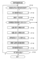
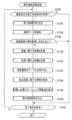
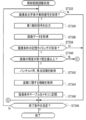
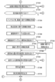
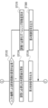
- FIG. 1 It is a flowchart which shows an example of the flow of the irradiation range adjustment process which concerns on 5th Embodiment.
- the conceptual diagram shows an example of a mode in which the display control processing program and the irradiation range adjustment processing program are installed in the computer in the management device from the storage medium in which the display control processing program and the irradiation range adjustment processing program according to the embodiment are stored. be.
- CPU is an abbreviation for "Central Processing Unit”.
- RAM is an abbreviation for "Random Access Memory”.
- ROM is an abbreviation for "Read Only Memory”.
- ASIC is an abbreviation for "Application Specific Integrated Circuit”.
- PLD is an abbreviation for "Programmable Logic Device”.
- FPGA is an abbreviation for "Field-Programmable Gate Array”.
- SoC is an abbreviation for "System-on-a-chip”.
- CMOS is an abbreviation for "Complementary Metal Oxide Semiconductor”.
- CCD is an abbreviation for "Charge Coupled Device”.
- SWIR is an abbreviation for "Short-Wavelength InfraRed”.
- TOF is an abbreviation for "Time of Flight”.
- LED is an abbreviation for "Light Emitting Diode”.
- SSD is an abbreviation for "Solid State Drive”.
- USB is an abbreviation for “Universal Serial Bus”.
- HDD is an abbreviation for “Hard Disk Drive”.
- EEPROM is an abbreviation for "Electrically Erasable and Programmable Read Only Memory”.
- EL is an abbreviation for "Electro-Luminescence”.
- a / D is an abbreviation for "Analog / Digital”.
- I / F is an abbreviation for "Interface”.
- UI is an abbreviation for "User Interface”.
- WAN is an abbreviation for "Wide Area Network”.
- CRT is an abbreviation for "Cathode Ray Tube”.
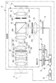
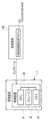
- the image pickup system 2 includes an image pickup device 10, a floodlight 110, a mounting member 4, and a management device 11.
- the image pickup system 2 is an example of the "imaging system” according to the technique of the present disclosure
- the image pickup device 10 is an example of the “imaging apparatus” according to the technique of the present disclosure
- the floodlight 110 is an example of the "imaging apparatus” according to the technique of the present disclosure.
- the mounting member 4 also serves as a swivel mechanism 9.
- the image pickup device 10 is installed on an indoor / outdoor road surface, a pillar, a wall, a floor, a part of a building (for example, a rooftop), or the like via a mounting member 4, and is a monitoring target (hereinafter, also referred to as an “imaging area”) as a subject. ) Is imaged, and a moving image is generated by capturing the image.
- the moving image includes a multi-frame image obtained by imaging.
- the image pickup device 10 transmits the moving image obtained by taking a picture to the management device 11 via the communication line 15.
- the management device 11 includes a display 13.
- an organic EL display is adopted as an example of the display 13.
- this is only an example, and may be another type of display such as a liquid crystal display, a plasma display, or a CRT display.
- the management device 11 receives the moving image transmitted by the imaging device 10, and the received moving image is displayed on the display 13.
- the mounting member 4 has a support column 6 and a support base 8 attached to the upper part of the support column 6.
- An image pickup device 10 and a floodlight 110 are attached to the support base 8.
- the support base 8 can be swiveled with respect to the support column 6, and by this swivel, the image pickup device 10 and the floodlight 110 can also be swiveled together with the support base 8.
- the swivel mechanism 9 can rotate in a swivel direction (hereinafter, referred to as “pitch direction”) with the pitch axis PA as the central axis, and a swivel direction (hereinafter, “pitch direction”) with the yaw axis YA as the central axis. It is a two-axis swivel mechanism that can rotate in the yaw direction).
- the mounting member 4 also serves as the swivel mechanism 9.
- the technique of the present disclosure is not limited to this, and a three-axis swivel mechanism may be used.
- the swivel mechanism 9 is an example of the "first swivel mechanism” and the "second swivel mechanism” according to the technique of the present disclosure.
- the support base 8 further includes a swivel base 8A for swiveling the floodlight 110.
- the swivel table 8A is a table that supports the floodlight 110 from below, and can selectively swivel the floodlight 110 in the pitch direction and the yaw direction with respect to the image pickup device 10.
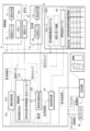
- the image pickup device 10 includes an image pickup optical system 12, a first image sensor 14, a second image sensor 16, an image pickup system position sensor 18, an image pickup system motor 20, a UI system device 22, and a control device. 24 is provided.
- the first image sensor 14 and the second image sensor 16 are located after the imaging optical system 12.
- the first image sensor 14 and the second image sensor 16 include a light receiving surface 14A and a light receiving surface 16A, respectively.
- the subject light indicating the subject S (hereinafter, also simply referred to as “subject light”) is imaged on the light receiving surfaces 14A and 16A by the imaging optical system 12, and the imaging region is formed by the first image sensor 14 and the second image sensor 16. It is imaged.
- the imaging optical system 12 is an example of the "first optical system" according to the technique of the present disclosure.
- the imaging optical system 12 includes a first optical system 28, an imaging system prism 30, a second optical system 32, and a third optical system 34.
- Subject light includes visible light, which is light in the visible wavelength range, and light having a wavelength longer than visible light (hereinafter, also simply referred to as "long wavelength light”) as light in different wavelength ranges.
- the first image sensor 14 captures long-wavelength light imaged on the light receiving surface 14A after the subject light is separated by the imaging optical system 12.
- the second image sensor 16 captures visible light imaged on the light receiving surface 16A after the subject light is separated by the imaging optical system 12.
- the long-wavelength light is an example of the "first wavelength region light” according to the technique of the present disclosure
- the visible light is an example of the “second wavelength region light” according to the technology of the present disclosure. Further, in the following, for convenience of explanation, long-wavelength light will be described as infrared light.
- the image pickup optical system 12 is provided with an image pickup system infrared light path and an image pickup system visible light path.
- a first optical system 28, an imaging system prism 30, and a second optical system 32 are arranged in order from the subject S side (object side) along the optical axis L1.
- the first optical system 28 transmits infrared light and visible light contained in the subject light.
- the imaging system prism 30 separates the subject light into infrared light and visible light, and guides the infrared light and visible light to the second optical system 32 and the third optical system 34, respectively.
- a first image sensor 14 is arranged after the second optical system 32. That is, the first image sensor 14 is located on the image side of the second optical system 32 and receives infrared light emitted from the second optical system 32.
- the first image sensor 14 is an infrared light two-dimensional image sensor and captures infrared light.
- the first image sensor 14 has a light receiving surface 14A.
- the light receiving surface 14A is formed by a plurality of photosensitive pixels (not shown) arranged in a matrix, each photosensitive pixel is exposed, and photoelectric conversion is performed for each photosensitive pixel.
- a plurality of photoelectric conversion elements having sensitivity to infrared light are adopted as the plurality of photosensitive pixels.
- the photoelectric conversion element includes an InGaAs photodiode in which an infrared light transmission filter is arranged and a CMOS read circuit.
- the InGaAs photodiode is illustrated here, the InGaAs photodiode is not limited to this, and a type 2 quantum well (T2SL; Simulation of Type-II Quantum Well) photodiode may be applied instead of the InGaAs photodiode.
- the first image sensor 14 is an example of the "first image sensor" according to the technique of the present disclosure.
- the optical path for visible light of the imaging system has an optical axis L1 and an optical axis L2.
- the optical axis L2 is an optical axis perpendicular to the optical axis L1.
- the first optical system 28 and the imaging system prism 30 are arranged in order from the subject S side along the optical axis L1.
- the optical axis L1 is branched into the optical axis L2 by the imaging system prism 30.
- the third optical system 34 is arranged along the optical axis L2 on the image side of the imaging system prism 30.
- the second image sensor 16 is arranged after the third optical system 34, that is, on the image side of the third optical system 34. In other words, the third optical system 34 is provided between the image pickup system prism 30 and the second image sensor 16.
- the second image sensor 16 receives visible light emitted from the third optical system 34.
- the second image sensor 16 is a visible light two-dimensional image sensor and captures visible light.
- the second image sensor 16 has a light receiving surface 16A.
- the light receiving surface 16A is formed by a plurality of photosensitive pixels (not shown) arranged in a matrix, each photosensitive pixel is exposed, and photoelectric conversion is performed for each photosensitive pixel.
- a plurality of photoelectric conversion elements having sensitivity to visible light are adopted as the plurality of photosensitive pixels.
- the photoelectric conversion element has a Si photodiode in which a color filter is arranged and a CMOS read circuit.
- the color filters are a filter corresponding to R (red), a filter corresponding to G (green), and a filter corresponding to B (blue), and are arranged on the light receiving surface 16A in a specific arrangement pattern.
- the X-Trans (registered trademark) sequence is adopted as a specific sequence pattern.
- the arrangement pattern is not limited to this, and may be another type of arrangement pattern such as a Bayer arrangement or a honeycomb arrangement.
- the second image sensor 16 is an example of the "second image sensor" according to the technique of the present disclosure.
- the first optical system 28 has a first lens group 28A, a second lens group 28B, a third lens group 28C, and a fourth lens group 28D in order from the subject S side.
- the first lens group 28A is a lens group having a positive refractive power
- the second lens group 28B is a lens group having a negative refractive power
- the third lens group 28C is a lens group having a positive refractive power
- the fourth lens group 28D is a lens group having a positive refractive power.
- the first optical system 28 has a first lens group 28A as a focus lens. It has a second lens group 28B and a third lens group 28C as zoom lenses.
- the second lens group 28B and the third lens group 28C are examples of the "first zoom lens” and the "fourth zoom lens” according to the technique of the present disclosure.
- the zoom lens in the present embodiment refers to a group of lenses that can be moved when adjusting the focal length.
- the first optical system 28 includes a first lens group 28A, a second lens group 28B, a third lens group 28C, a fourth lens group 28D, an aperture 28E, and a fifth lens group 28F.
- Each of the first lens group 28A, the second lens group 28B, the third lens group 28C, the fourth lens group 28D, and the fifth lens group 28F is composed of a plurality of lenses.
- the first lens group 28A, the second lens group 28B, the third lens group 28C, the fourth lens group 28D, the aperture 28E, and the fifth lens group 28F are the "first optical elements" according to the technique of the present disclosure. This is an example.
- the first lens group 28A, the second lens group 28B, the third lens group 28C, the fourth lens group 28D, and the fifth lens group 28F are arranged in order from the subject S side along the optical axis L1.
- the third lens group 28C has an exit surface 28C1
- the fourth lens group 28D has an incident surface 28D1 and an exit surface 28D2.
- the exit surface 28C1 is the surface of the third lens group 28C located on the image side most
- the incident surface 28D1 is the surface of the fourth lens group 28D located on the subject S side most, and the exit surface 28D2. Is the surface located on the image side of the fourth lens group 28D.
- the diaphragm 28E is arranged between the exit surface 28C1 and the entrance surface 28D1.
- the diaphragm 28E is located on the subject S side of the fourth lens group 28D in the direction of the optical axis L1 and adjacent to the fourth lens group 28D (for example, the exit surface 28C1 and the incident surface 28D1). (Between). Note that this is only an example, and the aperture 28E may be arranged in the fourth lens group 28D.
- Each of the first lens group 28A and the fourth lens group 28D is a fixed lens group.
- the fixed lens group is a lens group fixed to the image plane at the time of scaling.
- Each of the second lens group 28B and the third lens group 28C is a moving lens group.
- the moving lens group is a lens group in which the distance from the adjacent lens group is changed by moving along the optical axis L1 direction at the time of scaling.
- Each of the first lens group 28A, the third lens group 28C, the fourth lens group 28D, and the fifth lens group 28F is a lens group having a positive power, and the second lens group 28B has a negative power. It is a lens group.
- first lens group 28A, the second lens group 28B, the third lens group 28C, the fourth lens group 28D, the fifth lens group 28F, and the like are illustrated here, the techniques of the present disclosure are illustrated. Is not limited to this.
- at least one of the first lens group 28A, the second lens group 28B, the third lens group 28C, the fourth lens group 28D, and the fifth lens group 28F may be one lens.
- the focus position is adjusted by the first optical system 28.
- the adjustment of the focus position is realized by, for example, the front lens focus method.
- the front lens focus method the first lens group 28A moves along the optical axis L1 direction, so that infrared light is imaged on the light receiving surface 14A at a focusing position according to the distance to the subject S.
- the "focus position" referred to here refers to the position of the first lens group 28A on the optical axis L1 in a state of being in focus.
- the first lens group 28A is an example of the "first focus lens" according to the technique of the present disclosure.
- the front focus method is adopted, but the technique of the present disclosure is not limited to this, and the whole group extension method, the inner focus method, or the rear focus method is adopted. May be good.
- the "focus position" in the case of the all-group extension method, the inner focus method, or the rear focus method is a lens or a lens group that is moved along the optical axis L1 in order to adjust the focus position on the optical axis L1. Refers to the position in the in-focus state.
- the aperture 28E has an opening 28E1, and the subject light passes through the opening 28E1.
- the opening 28E1 is arranged at a position where the peripheral light rays of the subject light pass through the optical axis L1.
- the diaphragm 28E is a movable diaphragm whose diameter of the opening 28E1 can be changed. That is, the amount of the subject light indicating the subject S can be changed by the aperture 28E.
- the first optical system 28 forms an intermediate image S1 on the optical axis L1.
- the intermediate image S1 is formed between the aperture 28E and the imaging system prism 30 by the first optical system 28. More specifically, the intermediate image S1 has an exit surface 28D2 which is the most image-side surface of the fourth lens group 28D and the most subject S side of the fifth lens group 28F by the first optical system 28. It is formed between the incident surface 28F1 and the incident surface 28F1.
- the fifth lens group 28F is arranged between the intermediate image S1 and the imaging system prism 30 on the optical axis L1.
- the fifth lens group 28F Since the fifth lens group 28F has a positive power, the luminous flux of the subject light is transferred to the imaging system prism 30 by giving a converging action to the subject light incident on the fifth lens group 28F as divergent light. Make it incident. That is, the fifth lens group 28F accommodates the peripheral light rays of the incident subject light in the imaging system prism 30 by a positive refractive power.
- the first optical system 28 emits the incident subject light to the imaging system prism 30.
- the imaging system prism 30 is an example of the "separation optical system" according to the technique of the present disclosure.
- the imaging system prism 30 separates the subject light transmitted through the first optical system 28 into near-infrared light and visible light on the selective reflection surface 30A.
- the imaging system prism 30 transmits infrared light and reflects visible light. That is, the imaging system prism 30 guides infrared light to the second optical system 32 along the optical axis L1 and guides visible light to the third optical system 34 along the optical axis L2.
- the technique of the present disclosure is not limited to this, and the subject light is visible as infrared light by a dichroic mirror and / or a half mirror instead of the image pickup system prism 30. It may be separated from the light. However, when a half mirror is used, it is preferable that the light in an unnecessary wavelength range is removed by the filter from the infrared light and the visible light obtained by separating the subject light.
- Infrared light separated from the subject light by the imaging system prism 30 passes through the second optical system 32.
- the second optical system 32 is arranged on the image side of the imaging system prism 30 along the optical axis L1 direction. In other words, the second optical system 32 is arranged on the side where infrared light is emitted from the imaging system prism 30.
- the second optical system 32 includes a relay lens 32A and an aperture 32B.
- the relay lens 32A is a lens having a positive power. Infrared light emitted from the imaging system prism 30 is incident on the relay lens 32A, and the relay lens 32A forms an image of the incident infrared light on the light receiving surface 14A.
- the aperture 32B has an opening 32B1, and the subject light passes through the opening 32B1.
- the opening 32B1 is arranged at a position where the peripheral light rays of the subject light pass through the optical axis L1.
- the diaphragm 32B is a movable diaphragm whose diameter of the opening 32B1 can be changed. That is, the amount of the subject light indicating the subject S can be changed by the aperture 32B.
- the infrared light obtained by separating the subject light by the imaging system prism 30 is, for example, light having a longer wavelength than the visible light among the subject lights, and here, 1400 nanometers (nm) or more and 2600 nm or less. Light having an infrared light wavelength range of is adopted. Visible light is light having a short wavelength of 700 nm or less.
- the infrared light of the subject light passes through the imaging system prism 30 with a transmittance of about 90% (percentage), and the visible light of the subject light has a reflectance of more than about 90% and the selective reflecting surface 30A. Reflects on.
- the image pickup system position sensor 18 and the image pickup system motor 20 are connected to the image pickup optical system 12.
- the image pickup system position sensor 18 is a device that detects the position of a lens group or a relay lens or the like constituting the image pickup optical system 12, the aperture of the aperture, or the like.
- the image pickup system motor 20 is a device that applies power to a lens group, a relay lens, or an aperture that constitutes the image pickup optical system 12.
- the UI system device 22 is a device that receives instructions from a user of the imaging system 2 (hereinafter, simply referred to as a "user") and presents various information to the user.
- Devices that receive instructions from the user include a touch panel and hard keys.
- Devices that present various information to the user include a display and a speaker.
- the first image sensor 14, the second image sensor 16, the image pickup system position sensor 18, the image pickup system motor 20, and the UI system device 22 are connected to the control device 24.
- the first image sensor 14, the second image sensor 16, the image pickup system position sensor 18, the image pickup system motor 20, and the UI system device 22 are controlled by the control device 24.
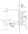
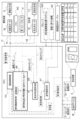
- the control device 24 includes a CPU 24A, a storage 24B, and a memory 24C, and the CPU 24A, the storage 24B, and the memory 24C are connected to the bus 44.
- bus 44 In the examples shown in FIGS. 3A to 3C, one bus is shown as the bus 44 for convenience of illustration, but a plurality of buses may be used.
- the bus 44 may be a serial bus or a parallel bus including a data bus, an address bus, a control bus, and the like.
- the storage 24B stores various parameters and various programs.
- the storage 24B is a non-volatile storage device.
- EEPROM is adopted as an example of the storage 24B.
- the EEPROM is merely an example, and an HDD and / or SSD or the like may be applied as the storage 24B instead of or together with the EEPROM.
- the memory 24C temporarily stores various information and is used as a work memory.
- An example of the memory 24C is RAM, but the memory 24C is not limited to this, and other types of storage devices may be used.
- the imaging system position sensor 18 includes a first position sensor 18A, a second position sensor 18B, a third position sensor 18C, a fourth position sensor 18D, a fifth position sensor 18E, and a sixth position sensor 18F.
- the first position sensor 18A, the second position sensor 18B, the third position sensor 18C, and the fourth position sensor 18D are used for the first optical system 28.
- the fifth position sensor 18E and the sixth position sensor 18F are used for the second optical system 32.
- a potentiometer is adopted as an example of each of the first position sensor 18A, the second position sensor 18B, the third position sensor 18C, the fourth position sensor 18D, the fifth position sensor 18E, and the sixth position sensor 18F. There is.
- the first position sensor 18A detects the position of the first lens group 28A on the optical axis L1.
- the second position sensor 18B detects the position of the second lens group 28B on the optical axis L1.
- the third position sensor 18C detects the position of the third lens group 28C on the optical axis L1.
- the fourth position sensor 18D detects the diameter of the opening 28E1.
- the fifth position sensor 18E detects the diameter of the opening 32B1.
- the sixth position sensor 18F detects the position of the relay lens 32A on the optical axis L1.
- the first position sensor 18A, the second position sensor 18B, the third position sensor 18C, the fourth position sensor 18D, the fifth position sensor 18E, and the sixth position sensor 18F are connected to the bus 44, and the CPU 24A is the third position sensor.
- the detection result of the 1st position sensor 18A, the detection result of the 2nd position sensor 18B, the detection result of the 3rd position sensor 18C, the detection result of the 4th position sensor 18D, the detection result of the 5th position sensor 18E, and The detection result of the 6th position sensor 18F is acquired.
- the image pickup system motor 20 is an example of the "first drive source” according to the technique of the present disclosure, and is an example of the first motor 20A2, the second motor 20B2, the third motor 20C2, the fourth motor 20D2, the fifth motor 20E2, and the third motor 20E2. It is equipped with 6 motors 20F2. Further, the image pickup apparatus 10 includes a first motor driver 20A1, a second motor driver 20B1, a third motor driver 20C1, a fourth motor driver 20D1, a fifth motor driver 20E1, and a sixth motor driver 20F1.
- the first motor driver 20A1 is connected to the first motor 20A2.
- the second motor driver 20B1 is connected to the second motor 20B2.
- the third motor driver 20C1 is connected to the third motor 20C2.
- the fourth motor driver 20D1 is connected to the fourth motor 20D2.
- the fifth motor driver 20E1 is connected to the fifth motor 20E2.
- the sixth motor driver 20F1 is connected to the sixth motor 20F2.
- the first motor driver 20A1, the second motor driver 20B1, the third motor driver 20C1, the fourth motor driver 20D1, the fifth motor driver 20E1, and the sixth motor driver 20F1 are connected to the bus 44.
- the first motor driver 20A1 controls the first motor 20A2 under the control of the CPU 24A.
- the second motor driver 20B1 controls the second motor 20B2 under the control of the CPU 24A.
- the third motor driver 20C1 controls the third motor 20C2 under the control of the CPU 24A.
- the fourth motor driver 20D1 controls the fourth motor 20D2 under the control of the CPU 24A.
- the fifth motor driver 20E1 controls the fifth motor 20E2 under the control of the CPU 24A.
- the sixth motor driver 20F1 controls the sixth motor 20F2 under the control of the CPU 24A.
- the imaging device 10 includes a first moving mechanism 20A3, a second moving mechanism 20B3, a third moving mechanism 20C3, a fourth moving mechanism 20D3, a fifth moving mechanism 20E3, and a sixth moving mechanism 20F3.
- the first moving mechanism 20A3 has a first motor 20A2.
- the second moving mechanism 20B3 has a second motor 20B2.
- the third moving mechanism 20C3 has a third motor 20C2.
- the fourth moving mechanism 20D3 has a fourth motor 20D2.
- the fifth moving mechanism 20E3 has a fifth motor 20E2.
- the sixth moving mechanism 20F3 has a sixth motor 20F2.
- the first lens group 28A is connected to the first moving mechanism 20A3.
- the first moving mechanism 20A3 operates by receiving the power generated by the first motor 20A2 under the control of the first motor driver 20A1 to move the first lens group 28A in the optical axis L1 direction.
- the second lens group 28B is connected to the second moving mechanism 20B3.
- the second moving mechanism 20B3 operates by receiving the power generated by the second motor 20B2 under the control of the second motor driver 20B1 to move the second lens group 28B in the optical axis L1 direction.
- the third lens group 28C is connected to the third moving mechanism 20C3.
- the third moving mechanism 20C3 operates by receiving the power generated by the third motor 20C2 under the control of the third motor driver 20C1 to move the third lens group 28C in the optical axis L1 direction.
- a diaphragm 28E is connected to the fourth moving mechanism 20D3.
- the fourth moving mechanism 20D3 operates by receiving the power generated by the fourth motor 20D2 under the control of the fourth motor driver 20D1 to adjust the opening degree 28E1 of the diaphragm 28E.
- a diaphragm 32B is connected to the fifth moving mechanism 20E3.
- the fifth moving mechanism 20E3 operates by receiving the power generated by the fifth motor 20E2 under the control of the fifth motor driver 20E1 to adjust the opening degree 32B1 of the aperture 32B.
- a relay lens 32A is connected to the sixth moving mechanism 20F3.
- the sixth moving mechanism 20F3 operates by receiving the power generated by the sixth motor 20F2 under the control of the sixth motor driver 20F1 to move the relay lens 32A in the optical axis L1 direction.
- the third optical system 34 transmits the separated visible light and guides it to the second image sensor 16.
- the third optical system 34 is arranged on the image side of the imaging system prism 30 along the optical axis L2 direction, and includes a relay lens 34A and an aperture 34B.
- the diaphragm 34B and the relay lens 34A are arranged in order from the subject S side along the optical axis L2. That is, the diaphragm 34B is arranged at a position adjacent to the relay lens 34A on the subject S side of the relay lens 34A in the optical axis L2 direction.
- the diaphragm 34B has an opening 34B1 on the optical axis L2.
- the opening 34B1 is in a conjugate positional relationship with the opening 28E1 on the optical axis L1.
- the diaphragm 34B is a movable diaphragm in which the diameter of the opening 34B1 can be changed. That is, the amount of visible light can be changed by the aperture 34B.
- Each of the diaphragm 28E and the diaphragm 34B is a diaphragm that can be controlled independently.
- the relay lens 34A is a lens having positive power.
- the relay lens 34A forms an image of visible light incident on the light receiving surface 16A through the diaphragm 34B. In this way, visible light is incident on the third optical system 34 through the diaphragm 34B, and the third optical system 34 emits the incident visible light to the light receiving surface 16A.
- the imaging system position sensor 18 includes a seventh position sensor 18G and an eighth position sensor 18H.
- the seventh position sensor 18G and the eighth position sensor 18H are used for the third optical system 34.
- a potentiometer is adopted as an example of each of the 7th position sensor 18G and the 8th position sensor 18H.
- the 7th position sensor 18G detects the diameter of the opening 34B1.
- the eighth position sensor 18H detects the position of the relay lens 34A on the optical axis L2.
- the 7th position sensor 18G and the 8th position sensor 18H are connected to the bus 44, and the CPU 24A acquires the detection result by the 7th position sensor 18G and the detection result by the 8th position sensor 18H.
- the imaging system motor 20 includes a seventh motor 20G2 and an eighth motor 20H2. Further, the image pickup apparatus 10 includes a seventh motor driver 20G1 and an eighth motor driver 20H1. The seventh motor driver 20G1 is connected to the seventh motor 20G2. The eighth motor driver 20H1 is connected to the eighth motor 20H2.
- the 7th motor driver 20G1 and the 8th motor driver 20H1 are connected to the bus 44.
- the seventh motor driver 20G1 controls the seventh motor 20G2 under the control of the CPU 24A.
- the eighth motor driver 20H1 controls the eighth motor 20H2 under the control of the CPU 24A.
- the image pickup device 10 includes a seventh moving mechanism 20G3 and an eighth moving mechanism 20H3.
- the seventh moving mechanism 20G3 has a seventh motor 20G2.
- the eighth moving mechanism 20H3 has an eighth motor 20H2.
- a diaphragm 34B is connected to the 7th moving mechanism 20G3.
- the seventh moving mechanism 20G3 operates by receiving the power generated by the seventh motor 20G2 under the control of the seventh motor driver 20G1 to adjust the opening degree 34B1 of the aperture 34B.
- a relay lens 34A is connected to the eighth moving mechanism 20H3.
- the eighth moving mechanism 20H3 operates by receiving the power generated by the eighth motor 20H2 under the control of the eighth motor driver 20H1 to move the relay lens 34A in the optical axis L2 direction.
- the image pickup apparatus 10 includes a communication I / F 33, and the communication I / F 33 is connected to the bus 44.
- the communication I / F 33 is, for example, a network interface, and controls the transmission of various information between the CPU 24A and the management device 11 via the network.
- An example of a network is a WAN such as the Internet or a public communication network.
- a first image sensor 14 and a second image sensor 16 are connected to the bus 44, and the CPU 24A controls the first image sensor 14 and the second image sensor 16 and also controls the first image sensor 14 and the second image sensor 16. Image data is acquired from each of the image sensors 16.
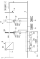
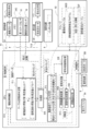
- the floodlight 110 includes a floodlight optical system 112, a first light source 114, a second light source 116, a floodlight system position sensor 118, a floodlight system motor 120, and a control device 124. ..
- the floodlight 110 is an example of a "floodlight” according to the technique of the present disclosure
- the floodlight optical system 112 is an example of a "second optical system” according to the technique of the present disclosure.
- the first light source 114 and the second light source 116 are located after the projection optical system 112.
- the light emitted from the first light source 114 and the second light source 116 is emitted to the subject S side by the projection optical system 112. That is, the light is projected by the first light source 114 and the second light source 116.
- the floodlight optical system 112 has optical specifications corresponding to the image pickup optical system 12. That is, as shown in FIG. 4 as an example, the projection optical system 112 is composed of optical elements corresponding to the optical elements constituting the imaging optical system 12.
- the "corresponding optical specifications" according to the technology of the present disclosure include an error that can be tolerated in the technical field related to the technology of the present disclosure, in addition to the meaning of exactly the same optical specifications as the imaging optical system 12. For example, it also includes the meaning of substantially the same optical specifications including (errors such as dimensions that may occur at the time of design and manufacturing) and the meaning of optical specifications having a similar relationship with the imaging optical system 12.
- optical specifications having a similar relationship with the imaging optical system 12 are, for example, the number of lenses constituting the lens group, the spacing between the optical elements, and the distance between the imaging optical system 12 and the projection optical system 112. It also refers to optical specifications in which the optical characteristics including the size of the optical element are similar.
- the projection optical system 112 includes a first optical system 128, a projection system prism 130, a second optical system 132, and a third optical system 134.
- the light projecting optical system 112 is provided with an optical path for light projecting infrared light and an optical path for light projecting visible light.
- the first optical system 128, the projection system prism 130, and the second optical system 132 are arranged in order from the subject S side along the optical axis L3.
- a first light source 114 is arranged after the second optical system 132.
- the first light source 114 is a light source capable of emitting light having a wavelength longer than that of visible light.
- infrared light is adopted as an example of light having a wavelength longer than that of visible light.
- An example of infrared light is light having an infrared light wavelength range of 1400 nm or more and 2600 nm or less.
- the first light source 114 is, for example, a laser diode.
- a laser diode is illustrated, but the present invention is not limited to this, and other types of light sources such as an LED diode may be applied.
- the first light source 114 is an example of the "first light source" according to the technique of the present disclosure.
- the second optical system 132 transmits the infrared light emitted from the first light source 114 and guides it to the projection system prism 130. More specifically, the second optical system 132 is arranged on the light source side of the projection system prism 130 along the optical axis L3 direction, and includes a relay lens 132A.
- the relay lens 132A is a lens having a positive power. Infrared light emitted from the first light source 114 is incident on the relay lens 132A, and the relay lens 132A transmits the incident infrared light and guides the incident infrared light to the projection prism 130.
- the optical path for visible light of the projection system has an optical axis L3 and an optical axis L4.
- the optical axis L4 is an optical axis perpendicular to the optical axis L3.
- the first optical system 128 and the projection system prism 130 are arranged in order from the subject S side along the optical axis L3.
- the third optical system 134 is arranged along the optical axis L4 on the light source side of the projection system prism 130.
- the third optical system 134 includes a relay lens 134A and an aperture 134B.
- the diaphragm 134B and the relay lens 134A are arranged in order from the subject S side along the optical axis L4. That is, the diaphragm 134B is arranged at a position adjacent to the relay lens 134A on the subject S side of the relay lens 134A in the optical axis L4 direction.
- the second light source 116 is arranged after the third optical system 134, that is, on the light source side of the third optical system 134.
- the second light source 116 is, for example, a laser diode.
- a laser diode is illustrated, but the present invention is not limited to this, and other types of light sources such as an LED diode may be applied.
- the second light source 116 is an example of the "second light source" according to the technique of the present disclosure.
- the third optical system 134 transmits the visible light emitted from the second light source 116 and guides it to the projection system prism 130 via the diaphragm 134B.
- the relay lens 134A is a lens having a positive power, and guides the visible light emitted from the second light source 116 to the diaphragm 134B.
- the diaphragm 134B has an opening 134B1 on the optical axis L4.
- the opening 134B1 is in a conjugate positional relationship with the opening 128E1 on the optical axis L3.
- the diaphragm 134B is a movable diaphragm in which the diameter of the opening 134B1 can be changed. That is, the amount of visible light can be changed by the aperture 134B.
- Each of the diaphragm 128E and the diaphragm 134B is a diaphragm that can be controlled independently.
- the floodlight prism 130 is an example of a "compositing optical system" according to the technique of the present disclosure.
- the projection prism 130 synthesizes the infrared light emitted from the first light source 114 and the visible light emitted from the second light source 116, and guides the infrared light to the first optical system 128.
- the first optical system 128 transmits infrared light and visible light. That is, the first optical system 128 emits light including infrared light and visible light synthesized by the projection system prism 130 toward the subject S side.
- the floodlight prism 130 synthesizes infrared light transmitted through the second optical system 132 and visible light transmitted through the third optical system 134 on the selective reflection surface 130A.
- the projection prism 130 transmits infrared light and reflects visible light. That is, the light projecting prism 130 guides infrared light to the first optical system 128 along the optical axis L3 and guides visible light to the first optical system 128 along the optical axis L3.
- the technique of the present disclosure is not limited to this, and infrared light and visible light are used instead of the projection prism 130 by a dichroic mirror and / or a half mirror. And may be synthesized. However, when a half mirror is used, it is preferable that the light in an unnecessary wavelength range is removed by the filter from the light obtained by the synthesis.
- the first optical system 128 has a first lens group 128A, a second lens group 128B, a third lens group 128C, and a fourth lens group 128D in order from the subject S side.
- the first lens group 128A is a lens group having a positive refractive power
- the second lens group 128B is a lens group having a negative refractive power
- the third lens group 128C is a lens group having a positive refractive power.
- the fourth lens group 128D is a lens group having a positive refractive power.
- the first optical system 128 has a first lens group 128A as a focus lens. It has a second lens group 128B and a third lens group 128C as zoom lenses.
- the second lens group 128B and the third lens group 128C are examples of the "second zoom lens", the "third zoom lens", and the "fourth zoom lens” according to the technique of the present disclosure.
- the first optical system 128 includes a first lens group 128A, a second lens group 128B, a third lens group 128C, a fourth lens group 128D, an aperture 128E, and a fifth lens group 128F.
- Each of the first lens group 128A, the second lens group 128B, the third lens group 128C, the fourth lens group 128D, and the fifth lens group 128F is composed of a plurality of lenses.
- the first lens group 128A, the second lens group 128B, the third lens group 128C, the fourth lens group 128D, the aperture 128E, and the fifth lens group 128F are the "second optical elements" according to the technique of the present disclosure. This is an example.
- the first lens group 128A, the second lens group 128B, the third lens group 128C, the fourth lens group 128D, and the fifth lens group 128F are arranged in order from the subject S side along the optical axis L3.
- the third lens group 128C has an incident surface 128C1
- the fourth lens group 128D has an exit surface 128D1 and an incident surface 128D2.
- the incident surface 128C1 is the surface of the third lens group 128C located closest to the light source
- the exit surface 128D1 is the surface of the fourth lens group 128D located closest to the subject S
- the incident surface 128D2 Is the surface of the fourth lens group 128D located on the light source side.
- the diaphragm 128E is arranged between the entrance surface 128C1 and the exit surface 128D1.
- the diaphragm 128E is located on the subject S side of the fourth lens group 128D in the direction of the optical axis L3 and adjacent to the fourth lens group 128D (for example, the incident surface 128C1 and the emitting surface 128D1).
- the aperture 128E may be arranged in the fourth lens group 128D.
- Each of the first lens group 128A and the fourth lens group 128D is a fixed lens group.
- the fixed lens group is a lens group fixed to the light source at the time of scaling.
- Each of the second lens group 128B and the third lens group 128C is a moving lens group.
- the moving lens group is a lens group in which the distance from the adjacent lens group is changed by moving along the optical axis L3 direction at the time of scaling.
- Each of the first lens group 128A, the third lens group 128C, the fourth lens group 128D, and the fifth lens group 128F is a lens group having a positive power, and the second lens group 128B has a negative power. It is a lens group.
- lens groups such as the first lens group 128A, the second lens group 128B, the third lens group 128C, the fourth lens group 128D, and the fifth lens group 128F are illustrated. Is not limited to this.
- at least one of the first lens group 128A, the second lens group 128B, the third lens group 128C, the fourth lens group 128D, and the fifth lens group 128F may be one lens.
- the fifth lens group 128F is a fixed lens group that is immovable in the direction of the optical axis L3. Further, the fifth lens group 128F guides the synthesized light transmitted through the projection prism 130 to the first optical system 128 as non-variable light.
- the first optical system 128 realizes the adjustment of the optical arrangement (hereinafter, simply referred to as “pseudo-focus position”) corresponding to the focus position in the image pickup apparatus 10.
- the adjustment of the pseudo focus position is realized by, for example, the front lens focus method.
- the front lens focus method the first lens group 128A moves along the optical axis L3 direction, so that the light synthesized on the subject S is irradiated at a pseudo-focusing position corresponding to the distance to the subject S.
- the "pseudo-focusing position” referred to here refers to the position of the first lens group 128A on the optical axis L3 in the case of the image pickup apparatus 10 in a focused state.
- the first lens group 128A is an example of the "second focus lens" according to the technique of the present disclosure.
- the front focus method is adopted, but the technique of the present disclosure is not limited to this, and the whole group extension method, the inner focus method, or the rear focus method is adopted. May be good.
- the "pseudo-focusing position" in the case of the all-group extension method, the inner focus method, or the rear focus method is a lens or a lens group that is moved along the optical axis L3 in order to adjust the focus position on the optical axis L3. Refers to the position in the in-focus state among the positions of.
- the diaphragm 128E has an opening 128E1, and the combined light passes through the opening 128E1.
- the opening 128E1 is arranged at a position where the peripheral light rays of the combined light pass through the optical axis L3.
- the diaphragm 128E is a movable diaphragm in which the diameter of the opening 128E1 can be changed. That is, the amount of combined light can be changed by the diaphragm 128E.
- the floodlight system position sensor 118 and the floodlight system motor 120 are connected to the floodlight optical system 112.
- the light projecting system position sensor 118 is a device that detects the position of a lens group or a relay lens or the like constituting the light projecting optical system 112, the aperture of the aperture, or the like.
- the light projecting motor 120 is a device that applies power to a lens group, a relay lens, or an aperture that constitutes the light projecting optical system 112.
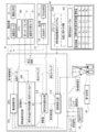
- the control device 124 includes a CPU 124A, a storage 124B, and a memory 124C, and the CPU 124A, the storage 124B, and the memory 124C are connected to the bus 144.
- bus 144 In the examples shown in FIGS. 5A to 5D, one bus is shown as bus 144 for convenience of illustration, but a plurality of buses may be used.
- the bus 144 may be a serial bus or a parallel bus including a data bus, an address bus, a control bus, and the like.
- the storage 124B stores various parameters and various programs.
- the storage 124B is a non-volatile storage device.
- EEPROM is adopted as an example of the storage 124B.
- the EEPROM is only an example, and an HDD and / or SSD or the like may be applied as the storage 124B instead of or together with the EEPROM.
- the memory 124C temporarily stores various information and is used as a work memory.
- An example of the memory 124C is RAM, but the memory 124C is not limited to this, and other types of storage devices may be used.
- the floodlight system position sensor 118 includes a first position sensor 118A, a second position sensor 118B, a third position sensor 118C, a fourth position sensor 118D, a fifth position sensor 118E, and a sixth position sensor 118F.
- the first position sensor 118A, the second position sensor 118B, the third position sensor 118C, and the fourth position sensor 118D are used for the first optical system 128.
- the fifth position sensor 118E and the sixth position sensor 118F are used for the second optical system 132.
- a potentiometer is adopted as an example of each of the first position sensor 118A, the second position sensor 118B, the third position sensor 118C, the fourth position sensor 118D, the fifth position sensor 118E, and the sixth position sensor 118F. There is.
- the first position sensor 118A detects the position of the first lens group 128A on the optical axis L3.
- the second position sensor 118B detects the position of the second lens group 128B on the optical axis L3.
- the third position sensor 118C detects the position of the third lens group 128C on the optical axis L3.
- the fourth position sensor 118D detects the diameter of the opening 128E1.
- the fifth position sensor 118E detects the diameter of the opening 132B1.
- the sixth position sensor 118F detects the position of the relay lens 132A on the optical axis L3.
- the first position sensor 118A, the second position sensor 118B, the third position sensor 118C, the fourth position sensor 118D, the fifth position sensor 118E, and the sixth position sensor 118F are connected to the bus 144, and the CPU 124A is the third. Detection result by 1 position sensor 118A, detection result by 2nd position sensor 118B, detection result by 3rd position sensor 118C, detection result by 4th position sensor 118D, 5th position sensor 118E, and 6th position sensor The detection result at 118F is acquired.
- the floodlight system motor 120 is an example of the "second drive source" according to the technique of the present disclosure, and includes the first motor 120A2, the second motor 120B2, the third motor 120C2, the fourth motor 120D2, the fifth motor 120E2, and the like. It is equipped with a sixth motor 120F2. Further, the floodlight 110 includes a first motor driver 120A1, a second motor driver 120B1, a third motor driver 120C1, a fourth motor driver 120D1, a fifth motor driver 120E1, and a sixth motor driver 120F1.
- the first motor driver 120A1 is connected to the first motor 120A2.
- the second motor driver 120B1 is connected to the second motor 120B2.
- the third motor driver 120C1 is connected to the third motor 120C2.
- the fourth motor driver 120D1 is connected to the fourth motor 120D2.
- the fifth motor driver 120E1 is connected to the fifth motor 120E2.
- the sixth motor driver 120F1 is connected to the sixth motor 120F2.
- the first motor driver 120A1, the second motor driver 120B1, the third motor driver 120C1, the fourth motor driver 120D1, the fifth motor driver 120E1, and the sixth motor driver 120F1 are connected to the bus 144.
- the first motor driver 120A1 controls the first motor 120A2 under the control of the CPU 124A.
- the second motor driver 120B1 controls the second motor 120B2 under the control of the CPU 124A.
- the third motor driver 120C1 controls the third motor 120C2 under the control of the CPU 124A.
- the fourth motor driver 120D1 controls the fourth motor 120D2 under the control of the CPU 124A.
- the fifth motor driver 120E1 controls the fifth motor 120E2 under the control of the CPU 124A.
- the sixth motor driver 120F1 controls the sixth motor 120F2 under the control of the CPU 124A.
- the floodlight 110 includes a first moving mechanism 120A3, a second moving mechanism 120B3, a third moving mechanism 120C3, a fourth moving mechanism 120D3, a fifth moving mechanism 120E3, and a sixth moving mechanism 120F3.
- the first moving mechanism 120A3 has a first motor 120A2.
- the second moving mechanism 120B3 has a second motor 120B2.
- the third moving mechanism 120C3 has a third motor 120C2.
- the fourth moving mechanism 120D3 has a fourth motor 120D2.
- the fifth moving mechanism 120E3 has a fifth motor 120E2.
- the sixth moving mechanism 120F3 has a sixth motor 120F2.
- the first lens group 128A is connected to the first moving mechanism 120A3.
- the first moving mechanism 120A3 operates by receiving the power generated by the first motor 120A2 under the control of the first motor driver 120A1 to move the first lens group 128A in the optical axis L3 direction.
- the second lens group 128B is connected to the second moving mechanism 120B3.
- the second moving mechanism 120B3 operates by receiving the power generated by the second motor 120B2 under the control of the second motor driver 120B1 to move the second lens group 128B in the optical axis L3 direction.
- a third lens group 128C is connected to the third moving mechanism 120C3.
- the third moving mechanism 120C3 operates by receiving the power generated by the third motor 120C2 under the control of the third motor driver 120C1 to move the third lens group 128C in the optical axis L3 direction.
- a diaphragm 128E is connected to the fourth moving mechanism 120D3.
- the fourth moving mechanism 120D3 adjusts the opening degree 128E1 of the aperture 128E by operating under the control of the fourth motor driver 120D1 by receiving the power generated by the fourth motor 120D2.
- a diaphragm 132B is connected to the fifth moving mechanism 120E3.
- the fifth moving mechanism 120E3 operates by receiving the power generated by the fifth motor 120E2 under the control of the fifth motor driver 120E1 to adjust the opening degree 132B1 of the diaphragm 132B.
- a relay lens 132A is connected to the sixth moving mechanism 120F3.
- the sixth moving mechanism 120F3 operates by receiving the power generated by the sixth motor 120F2 under the control of the sixth motor driver 120F1 to move the relay lens 132A in the optical axis L3 direction.
- the floodlight system position sensor 118 includes a seventh position sensor 118G and an eighth position sensor 118H.
- the seventh position sensor 118G and the eighth position sensor 118H are used for the third optical system 134.
- a potentiometer is adopted as an example of each of the 7th position sensor 118G and the 8th position sensor 118H.
- the 7th position sensor 118G detects the diameter of the opening 134B1.
- the eighth position sensor 118H detects the position of the relay lens 134A on the optical axis L4.
- the 7th position sensor 118G and the 8th position sensor 118H are connected to the bus 144, and the CPU 124A acquires the detection result of the 7th position sensor 118G and the detection result of the 8th position sensor 118H.
- the floodlight system motor 120 includes a seventh motor 120G2 and an eighth motor 120H2. Further, the floodlight 110 includes a seventh motor driver 120G1 and an eighth motor driver 120H1. The seventh motor driver 120G1 is connected to the seventh motor 120G2. The eighth motor driver 120H1 is connected to the eighth motor 120H2.
- the 7th motor driver 120G1 and the 8th motor driver 120H1 are connected to the bus 144.
- the seventh motor driver 120G1 controls the seventh motor 120G2 under the control of the CPU 124A.
- the eighth motor driver 120H1 controls the eighth motor 120H2 under the control of the CPU 124A.
- the floodlight 110 includes a seventh moving mechanism 120G3 and an eighth moving mechanism 120H3.
- the seventh moving mechanism 120G3 has a seventh motor 120G2.
- the eighth moving mechanism 120H3 has an eighth motor 120H2.
- a diaphragm 134 is connected to the seventh moving mechanism 120G3.
- the seventh moving mechanism 120G3 operates by receiving the power generated by the seventh motor 120G2 under the control of the seventh motor driver 120G1 to adjust the opening degree 132B1 of the aperture 132B.
- a relay lens 134A is connected to the eighth moving mechanism 120H3.
- the eighth moving mechanism 120H3 operates by receiving the power generated by the eighth motor 120H2 under the control of the eighth motor driver 120H1 to move the relay lens 134A in the optical axis L4 direction.
- the projection optical system 112 includes a shift lens 112A and a lens shift mechanism 112B2.
- the shift lens 112A changes the emission direction of the light emitted from the floodlight 110 by moving in a direction intersecting the optical axis L3 of the projection optical system 112.
- the floodlight optical system 112 includes a lens shift motor driver 112B1 and a lens shift mechanism 112B2.
- a shift lens 112A is connected to the lens shift mechanism 112B2.
- the lens shift mechanism 112B2 includes a lens shift motor 112B3.
- the lens shift motor 112B3 is, for example, a voice coil motor.
- the lens shift motor 112B3 is connected to the lens shift motor driver 112B1.
- the lens shift motor driver 112B1 is connected to the bus 144 and controls the lens shift motor 112B3 under the control of the CPU 124A.
- the lens shift mechanism 112B2 operates by receiving the power generated by the lens shift motor 112B3 under the control of the CPU 124A to move the shift lens 112A in the direction intersecting the optical axis L3.
- the direction intersecting the optical axis L3 refers to, for example, a direction perpendicular to the optical axis L3.
- the lens shift position sensor 112C detects the shift amount of the shift lens 112A.
- the lens shift position sensor 112C is connected to the bus 144, and the CPU 124A acquires the detection result of the lens shift position sensor 112C.
- the lens shift mechanism 112B2 is an example of a "drive mechanism” according to the technique of the present disclosure
- the shift lens 112A is an example of a "third lens” according to the technique of the present disclosure.
- the floodlight 110 includes a communication I / F 133.
- the communication I / F 133 receives the control signal from the management device 11.
- the floodlight 110 is driven based on the control signal from the management device 11. More specifically, the communication I / F 133 is, for example, a network interface.
- the communication I / F 133 is communicably connected to the communication I / F 80 (see FIG. 6) of the management device 11 via a network, and controls transmission of various information to and from the management device 11.
- the communication I / F 133 requests the management device 11 to transmit information regarding the irradiation range of light.
- the management device 11 transmits information from the communication I / F 80 in response to a request from the floodlight 110.
- the management device 11 includes a display 13, a computer 60, a reception device 64, a communication I / F66, a communication I / F67, a communication I / F68, and a communication I / F80.
- the swivel mechanism 9 includes a yaw shaft swivel mechanism 71, a pitch shaft swivel mechanism 72, a motor 73, a motor 74, a driver 75, and a driver 76.
- the computer 60 includes a CPU 61, a storage 62, and a memory 63.
- the CPU 61 is an example of a "processor" in the technology of the present disclosure.
- Each of the display 13, the reception device 64, the CPU 61, the storage 62, the memory 63, and the communication I / Fs 66 to 68, 80 is connected to the bus 70.
- one bus is shown as the bus 70 for convenience of illustration, but a plurality of buses may be used.
- the bus 70 may be a serial bus or a parallel bus including a data bus, an address bus, a control bus, and the like.
- the memory 63 temporarily stores various information and is used as a work memory.
- An example of the memory 63 is a RAM, but the memory 63 is not limited to this, and other types of storage devices may be used.
- Various programs for the management device 11 (hereinafter, simply referred to as “management device programs”) are stored in the storage 62.
- the CPU 61 reads the management device program from the storage 62 and executes the read management device program on the memory 63 to control the entire management device 11.
- Communication I / F66 is, for example, a network interface.
- the communication I / F 66 is communicably connected to the communication I / F 33 of the image pickup apparatus 10 via a network, and controls transmission of various information with the image pickup apparatus 10.
- the communication I / F 66 requests the image pickup device 10 to transmit the captured image, and receives the captured image transmitted from the communication I / F 33 of the image pickup device 10 in response to the request for transmission of the captured image.
- Communication I / F67 and communication I / F68 are, for example, network interfaces.
- the communication I / F 67 is communicably connected to the driver 75 of the swivel mechanism 9 via a network.
- the CPU 61 controls the turning operation of the yaw axis turning mechanism 71 by controlling the motor 73 via the communication I / F 67 and the driver 75.
- the communication I / F 68 is communicably connected to the driver 76 of the swivel mechanism 9 via a network.
- the CPU 61 controls the turning operation of the pitch axis turning mechanism 72 by controlling the motor 74 via the communication I / F 68 and the driver 76.
- the communication I / F80 is, for example, a network interface.
- the communication I / F 80 is communicably connected to the communication I / F 133 of the floodlight 110 via a network, and controls transmission of various information to and from the floodlight 110.
- the communication I / F 80 transmits information regarding the light irradiation range to the floodlight 110 to control the light irradiation in the floodlight 110.
- the reception device 64 is, for example, a keyboard, a mouse, a touch panel, or the like, and receives various instructions from the user.
- the CPU 61 acquires various instructions received by the receiving device 64 and operates according to the acquired instructions. For example, when the reception device 64 receives the processing content for the image pickup device 10, the floodlight 110 and / or the swivel mechanism 9, the CPU 61 swivels the image pickup device 10, the floodlight 110 and / or the swivel according to the instruction content received by the reception device 64.
- the mechanism 9 is operated.
- the display 13 displays various information under the control of the CPU 61. Examples of the various information displayed on the display 13 include the contents of various instructions received by the reception device 64, image data received by the communication I / F 66, and the like. In this way, the computer 60 controls the display 13 to display the captured image received by the communication I / F 66.
- the motor 73 In the turning mechanism 9, the motor 73 generates power under the control of the driver 75.
- the yaw axis swivel mechanism 71 swivels the image pickup device 10 and / or the floodlight 110 in the yaw direction by receiving the power generated by the motor 73.
- the motor 74 generates power by driving under the control of the driver 76.
- the pitch axis swivel mechanism 72 swivels the image pickup device 10 and / or the floodlight 110 in the pitch direction by receiving the power generated by the motor 74.
- the floodlight 110 is swiveled in the yaw direction and / or the pitch direction by transmitting power via the swivel base 8A.
- the floodlight 110 projects light onto the subject S.
- the floodlight 110 irradiates the subject S with light to compensate for the insufficient amount of light for the subject S.
- the subject S that is, the range imaged by the imaging device 10 (hereinafter, also simply referred to as “imaging range”) and the floodlight.
- imaging range the range imaged by the imaging device 10
- irradiation range the range of light irradiated by 110
- the optical specifications of the image pickup apparatus 10 and the optical specifications of the floodlight 110 do not correspond to each other, it becomes difficult to match the image pickup range and the floodlight irradiation range.
- matching the irradiation range and the imaging range means that the irradiation range and the imaging range are completely matched, and the subject S can be imaged by the imaging device 10. It also means that the irradiation range and the imaging range correspond to each other.
- the image pickup device 10 and the floodlight 110 are provided with optical systems having optical specifications corresponding to each other.
- the optical elements can be adjusted in common for the image pickup device 10 and the floodlight 110.
- FIG. 7 as an example, the adjustment of the imaging range in the imaging device 10 and the irradiation range in the floodlight 110 can be easily matched.
- the CPU 61 is connected to the image pickup system motor 20 via a communication line 15, and a control signal for the image pickup system motor 20 that drives an optical element in the image pickup apparatus 10 is transmitted to the communication line 15. Output via.
- the communication line 15 is branched and is also connected to the floodlight 110. Therefore, the CPU 61 also outputs a control signal to the floodlight system motor 120 that drives the optical element in the floodlight 110 via the communication line 15. That is, the CPU 61 controls the image pickup system motor 20 by outputting a control signal to the image pickup system motor 20. Further, the CPU 61 controls the light projecting motor 120 by outputting the same control signal to the light projecting motor 120 as a signal for controlling the light projecting motor 120.
- the lens group constituting the projection optical system 112 is located at a position corresponding to the position of the lens group constituting the imaging optical system 12. Therefore, as shown in FIG. 7 as an example, the imaging range and the floodlight irradiation range are likely to match.
- the imaging range and the irradiation range are matched even when the optical specifications of the imaging device 10 and the floodlight 110 correspond to each other. It may be difficult to do.
- the relative arrangement of the image pickup device 10 and the floodlight 110 (for example, the angle of the optical axis and / or the distance between the devices) is significantly deviated from the predetermined conditions due to aged deterioration, initial failure, or the like. Cases and the like can be mentioned.
- the storage 62 stores the irradiation range adjustment processing program 62B, and the CPU 61 reads the irradiation range adjustment processing program 62B from the storage 62 and adjusts the irradiation range.
- the processing program 62B is executed on the memory 63.
- the CPU 61 executes the irradiation range adjustment processing program 62B on the memory 63 to calculate the drive source control unit 61A, the irradiation range determination unit 61B, the adjustment means determination unit 61C, and the adjustment amount. Operates as unit 61D.
- the reception device 64 receives instructions from the user regarding control of the imaging system such as focus control and zoom control for the imaging device 10 (hereinafter referred to as “imaging system control instructions”), and receives signals according to the received imaging system control instructions. (Hereinafter referred to as an imaging system control signal) is output to the drive source control unit 61A.
- the drive source control unit 61A acquires an image pickup system optical element control signal from the reception device 64.
- the drive source control unit 61A acquires a focus lens control signal and a zoom lens control signal as image pickup system optical element control signals from the reception device 64.
- the focus lens control signal is a signal that controls a focus lens, that is, a first lens group 28A as an example, and a zoom lens control signal is a zoom lens, that is, a first optical system 28 (hereinafter, “imaging system zoom lens”). It is a signal that controls (also referred to as).
- the drive source control unit 61A outputs the first control signal to the image pickup system motor 20 of the image pickup device 10 based on the image pickup system optical element control signal acquired from the reception device 64. Further, the drive source control unit 61A outputs a first control signal to the floodlight motor 120 of the floodlight 110 based on the image pickup system optical element control signal acquired from the reception device 64.
- the first control signal is an example of a "control signal" according to the technique of the present disclosure.
- the image pickup system motor 20 drives the optical element of the image pickup optical system 12 based on the first control signal. Further, the light projecting motor 120 drives the optical element of the light projecting optical system 112 based on the first control signal.
- the image pickup device 10 takes a picture of the subject light in a state where the image pickup device 10 and the floodlight 110 control the optical system based on the first control signal.
- the image data obtained by being imaged by the first image sensor 14 or the second image sensor 16 of the image pickup apparatus 10 is stored in the memory 24C.
- the irradiation range determination unit 61B acquires the image data stored in the memory 24C. Further, the irradiation range determination unit 61B performs image analysis processing on the acquired image data to detect the irradiation range of the subject S and the floodlight 110. Further, the irradiation range determination unit 61B determines whether the subject S is included in the irradiation range based on the detection result.
- the adjustment means determination unit 61C determines the adjustment means necessary for adjusting the irradiation range.
- the adjusting means refers to, for example, the swivel mechanism 9, the shift lens 112A, and the first optical system 128.
- the adjusting means determination unit 61C specifies the positional relationship between the imaging range and the irradiation range based on the result of the image analysis processing, and based on the determination result in the irradiation range determination unit 61B based on the specified positional relationship. Then, it is determined whether to adjust the irradiation range by turning the floodlight 110. If the determination is denied, the adjustment means determination unit 61C determines whether to operate the lens shift mechanism 112B2 of the floodlight 110 to perform adjustment based on the positional relationship between the imaging range and the irradiation range.
- the adjusting means determination unit 61C changes the position of the zoom lens of the floodlight 110, that is, the first optical system 128 (hereinafter, also referred to as “projection system zoom lens”) to cover the irradiation range. Determined to make adjustments.
- the adjustment amount calculation unit 61D calculates the adjustment amount according to each adjustment means based on the determination results. Specifically, the adjustment amount calculation unit 61D calculates the adjustment amount according to each adjustment means based on the positional relationship between the imaging range and the irradiation range.
- the adjustment amount refers to the adjustment amount by each adjustment means required to match the irradiation range with the imaging range. That is, the adjustment amount calculation unit 61D calculates the deviation amount between the imaging range and the irradiation range based on the positional relationship between the imaging range and the irradiation range, and calculates the adjustment amount required to eliminate the calculated deviation amount. ..
- the adjustment amount calculation unit 61D revolves the floodlight 110 with the swivel mechanism 9 based on the positional relationship between the imaging range and the irradiation range, that is, the swivel direction and the swivel angle (hereinafter referred to as swirl angle). (Also referred to as “turning amount”) is calculated, and the calculated turning amount is output to the drive source control unit 61A. Further, when the lens shift mechanism 112B2 of the floodlight 110 is operated to perform adjustment, the adjustment amount calculation unit 61D calculates the orientation adjustment amount based on the positional relationship between the imaging range and the irradiation range, and the calculated orientation adjustment amount is calculated.
- the orientation adjustment amount is the amount of shift in the direction intersecting the optical axis of the optical element by the lens shift mechanism 112B2.
- the adjustment amount calculation unit 61D moves the projection zoom lens based on the positional relationship between the imaging range and the irradiation range (hereinafter referred to as “the amount of movement of the projection zoom lens”. (Also referred to as “zoom lens movement amount”) is calculated, and the calculated zoom lens movement amount is output to the drive source control unit 61A.
- the drive source control unit 61A When the drive source control unit 61A acquires the swivel amount from the adjustment amount calculation unit 61D, the drive source control unit 61A outputs a second control signal indicating the swivel amount to the swivel mechanism 9.
- the swivel mechanism 9 swivels the floodlight 110 in the swivel direction and swivel angle of the floodlight 110 determined according to the second control signal input from the drive source control unit 61A.
- the irradiation range and the imaging range are aligned.
- the drive source control unit 61A When the drive source control unit 61A acquires the direction adjustment amount from the adjustment amount calculation unit 61D, the drive source control unit 61A outputs a third control signal indicating the direction adjustment amount to the lens shift motor 112B3 of the floodlight 110.
- the floodlight system motor 120 operates according to a third control signal input from the drive source control unit 61A, and moves the shift lens 112A in a direction intersecting the optical axis L3. As a result, the projection direction of the floodlight 110 is changed, and the irradiation range and the imaging range are aligned.
- the drive source control unit 61A When the drive source control unit 61A acquires the zoom lens movement amount from the adjustment amount calculation unit 61D, the drive source control unit 61A outputs a fourth control signal indicating the zoom lens movement amount to the floodlight system motor 120 of the floodlight 110.
- the projection system motor 120 adjusts the position of the projection system zoom lens according to the amount of movement of the zoom lens determined according to the fourth control signal. Specifically, the positional relationship between the first lens group 28A, the second lens group 28B, the third lens group 28C, the fourth lens group 28D, and the fifth lens group 28F is changed according to the amount of movement of the zoom lens.
- the irradiation range is expanded and the imaging range is included in the irradiation range.
- FIGS. 12A and 12B show an example of the flow of the irradiation range adjusting process executed by the CPU 61 of the management device 11 according to the irradiation range adjusting process program 62B.
- the flow of the irradiation range adjusting process shown in FIGS. 12A and 12B is an example of the "control method of the imaging system" in the technique of the present disclosure.
- step ST32 the drive source control unit 61A determines whether or not the image pickup system optical element control signal has been acquired from the reception device 64. If the image pickup system optical element control signal is not acquired from the reception device 64 in step ST32, the determination is denied and the irradiation range adjustment process proceeds to step ST46. When the image pickup system optical element control signal is acquired from the reception device 64 in step ST32, the determination is affirmed, and the irradiation range adjustment process proceeds to step ST34.
- step ST34 the drive source control unit 61A outputs the first control signal to the image pickup system motor 20 of the image pickup device 10 and the floodlight system motor 120 of the floodlight 110. After that, the irradiation range adjustment process shifts to step ST36.
- step ST36 the irradiation range determination unit 61B acquires image data from the memory 24C of the image pickup device 10. After that, the irradiation range adjustment process shifts to step ST38.
- the irradiation range determination unit 61B identifies the positional relationship between the imaging range and the irradiation range based on the image data acquired in step ST36, and based on the positional relationship between the specified imaging range and the irradiation range, Determine if the imaging range is included in the irradiation range.
- the determination is affirmed, and the irradiation range adjustment process shifts to step ST46. If the imaging range is not included in the irradiation range in step ST38, the determination is denied, and the irradiation range adjustment process shifts to step ST40.
- step ST40 the adjusting means determination unit 61C determines whether or not the irradiation range needs to be adjusted by the swivel mechanism 9 based on the positional relationship between the imaging range and the irradiation range. If adjustment by the swivel mechanism 9 is required in step ST40, the determination is affirmed, and the irradiation range adjustment process shifts to step ST42. If adjustment by the swivel mechanism 9 is not required in step ST42, the determination is denied, and the irradiation range adjustment process proceeds to step ST48 shown in FIG. 12B.
- step ST42 the adjustment amount calculation unit 61D calculates the turning amount required for adjusting the irradiation range based on the positional relationship between the imaging range and the irradiation range. After that, the irradiation range adjustment process shifts to step ST44.
- step ST44 the drive source control unit 61A outputs a second control signal corresponding to the turning amount calculated by the adjusting amount calculation unit 61D to the turning mechanism 9. After that, the irradiation range adjustment process shifts to step ST46.
- the adjusting means determination unit 61C determines whether or not the irradiation range needs to be adjusted by the lens shift mechanism 112B2 based on the positional relationship between the imaging range and the irradiation range. .. If it is necessary to adjust the irradiation range by the lens shift mechanism 112B2 in step ST48, the determination is affirmed, and the irradiation range adjustment process shifts to step ST50. If it is not necessary to adjust the irradiation range by the lens shift mechanism 112B2 in step ST48, the determination is denied, and the irradiation range adjustment process shifts to step ST54.
- step ST50 the adjustment amount calculation unit 61D calculates the orientation adjustment required for adjustment by the lens shift mechanism 112B2 based on the positional relationship between the imaging range and the irradiation range. After that, the irradiation range adjustment process proceeds to step ST52.
- step ST52 the drive source control unit 61A outputs a third control signal according to the direction adjustment amount acquired from the adjustment amount calculation unit 61D to the lens shift motor 112B3 of the floodlight 110.
- the irradiation range adjustment process shifts to step ST46 shown in FIG. 12A as an example.
- step ST54 the adjustment amount calculation unit 61D calculates the zoom lens movement amount required for adjusting the irradiation range based on the positional relationship between the imaging range and the irradiation range.
- the irradiation range adjustment process proceeds to step ST56.
- step ST56 the drive source control unit 61A outputs a fourth control signal according to the zoom lens movement amount calculated in step ST54 to the floodlight motor 120 of the floodlight 110.
- the irradiation range adjustment process shifts to step ST46 shown in FIG. 12A as an example.
- step ST46 the drive source control unit 61A determines whether or not the condition for terminating the irradiation range adjustment process (hereinafter, referred to as “end condition”) is satisfied.
- the end condition include a condition that the reception device 64 has received an instruction to end the irradiation range adjustment process. If the end condition is not satisfied in step ST46, the determination is denied and the irradiation range adjustment process proceeds to step ST32. If the end condition is satisfied in step ST46, the determination is affirmed and the irradiation range adjustment process ends.
- the image pickup system 2 has an image pickup device 10 including an image pickup optical system 12 and a floodlight 110 provided with a light projecting optical system 112, and the image pickup optical system 12 and the light projecting optical system 112 correspond to each other. It has an optical specification. Therefore, it becomes easy to accurately match both the irradiation range and the imaging range as compared with the case where the optical specifications of the imaging optical system 12 and the optical specifications of the projection optical system 112 do not correspond to each other.
- the drive source control unit 61A controls the imaging system motor 20 that drives the imaging optical system 12 and the projection system motor 120 that drives the projection optical system 112. Therefore, both the irradiation range and the imaging range can be accurately matched as compared with the case where both the irradiation range and the imaging range are manually matched.
- the drive source control unit 61A projects a signal for controlling the image pickup system motor 20 for driving the image pickup optical system 12 as a signal for controlling the light projector system motor 120 for driving the light projector optical system 112.
- the floodlight system motor 120 is controlled by outputting the light to the system motor 120 as well. Therefore, both the irradiation range and the imaging range can be accurately matched as compared with the case where both the irradiation range and the imaging range are manually matched.
- the arrangement of the lens of the light projecting optical system 112 is adjusted based on the control signal for the image pickup optical system 12. .. Therefore, as compared with the case where the positions of the lenses of the imaging optical system 12 and the floodlight optical system 112 are adjusted separately, it becomes easier to control the optical systems of the imaging device 10 and the floodlight 110, and the irradiation range and the imaging range are increased. Consistent high-precision imaging is possible.
- the lens included in the image pickup optical system 12 has a second lens group 28B and a third lens group 28C as zoom lenses
- the lens included in the projection optical system 112 is a second lens as a zoom lens. It has a group 128B and a third lens group 128C.
- the adjustment mechanism of the projection optical system 112 corresponds to the second lens group 28B and the third lens group 28C in the image pickup optical system 12 whose position is adjusted by the adjustment mechanism of the image pickup optical system 12 based on the control signal.
- the positions of the second lens group 128B and the third lens group 128C in the projection optical system 112 are aligned with the positions.
- the lens included in the imaging optical system 12 has a first lens group 28A as a focus lens
- the lens included in the projection optical system 112 has a first lens group 128A as a focus lens.
- the adjustment mechanism of the projection optical system 112 is positioned at a position corresponding to the first lens group 28A in the imaging optical system 12 whose position is adjusted by the adjustment mechanism of the imaging optical system 12 based on the control signal. Align the position of the first lens group 128A in the system 112. Therefore, as compared with the case where the position of the focus lens of the imaging optical system 12 and the position of the focus lens of the floodlight optical system 112 are adjusted separately, the focus control of each of the image pickup device 10 and the floodlight 110 becomes easier. It is possible to perform high-precision imaging in which the irradiation range and the imaging range are matched.
- the imaging optical system 12 has a first lens group 28A as a focus lens, and has a second lens group 28B and a third lens group 28C as zoom lenses.
- the technique of the present disclosure is not limited to this, and the imaging optical system 12 may include either a focus lens or a zoom lens.
- the imaging optical system 12 includes only the focus lens of the focus lens and the zoom lens
- the floodlight optical system 112 also includes only the focus lens of the focus lens and the zoom lens.
- the imaging optical system 12 includes only the zoom lens of the focus lens and the zoom lens
- the floodlight optical system 112 also includes only the zoom lens of the focus lens and the zoom lens. You just have to do it. In this case as well, the same effect as described above can be expected.
- the drive source control unit 61A controls the arrangement of the optical elements of the image pickup optical system 12 and the floodlight optical system 112, and then the drive source control unit 61A further adjusts the irradiation range in the floodlight 110. Since the imaging range and the irradiation range are matched with each other, high-precision imaging in which the irradiation range and the imaging range are more consistent is possible as compared with the case where the irradiation range is not adjusted.
- the irradiation range is adjusted based on the image data acquired by the image pickup device 10. Therefore, as compared with the case where the irradiation range is adjusted without using the image data, it is possible to perform high-precision imaging in which the irradiation range and the imaging range are matched.
- the control signals of the image pickup optical system 12 and the projection optical system 112 are shared, and then the lens shift mechanism 112B2 is operated to adjust the irradiation range. Therefore, as compared with the case where the control signal is not shared, the irradiation range can be easily adjusted, and high-precision imaging in which the irradiation range and the imaging range are matched becomes possible.
- the control signals of the image pickup optical system 12 and the projection optical system 112 are shared, and then the swivel mechanism 9 is operated to adjust the irradiation range. Therefore, as compared with the case where the control signal is not shared, the irradiation range can be easily adjusted, and high-precision imaging in which the irradiation range and the imaging range are matched becomes possible.
- the control signals of the imaging optical system 12 and the projection optical system 112 are shared, and then the position of the projection system zoom lens is changed to adjust the irradiation range. Therefore, as compared with the case where the control signal is not shared, the irradiation range can be easily adjusted, and high-precision imaging in which the irradiation range and the imaging range are matched becomes possible.
- the subject light is separated into visible light and light having a wavelength longer than that of visible light by the imaging system prism 30, and the subject S is imaged with respect to visible light by the second image sensor 16. 1
- the image sensor 14 captures the subject S for light having a wavelength longer than that of visible light. Therefore, an image showing the subject S for visible light and an image showing the subject S for light having a wavelength longer than that of visible light can be obtained at the same time.
- the image pickup device 10 has a plurality of optical systems. Since the signal for controlling the imaging optical system 12 is shared with the floodlight optical system 112 of the floodlight 110, the image pickup device 10 and the floodlight 110 are compared with the case where the image pickup optical system 12 and the floodlight optical system 112 are controlled, respectively.
- the optical system of the above can be easily adjusted, and even when irradiating and imaging light of a plurality of wavelengths, high-precision imaging in which the irradiation range and the imaging range are matched becomes possible.
- the imaging optical system 12 and the projection optical system 112 use branching and synthetic optical systems using the imaging system prism 30 and the projection system prism 130, respectively. Therefore, the number of optical elements to be controlled can be reduced, and the optical elements of the imaging optical system 12 and the floodlight optical system 112 can be more easily adjusted as compared with the case where the branching and synthetic optical systems are not provided. It becomes. Further, since the number of optical elements can be reduced, the image pickup device 10 and the floodlight 110 can be downsized and / or lightened.
- the long wavelength light which is the infrared light is the infrared light wavelength range of 1400 nm or more and 2600 nm or less, and the light in the wavelength range which has relatively little influence on the human eye is used. Compared with the case of using infrared light in the wavelength range, the output of infrared light can be increased.
- the technique of the present disclosure has been described with reference to an example in which light is projected onto the subject S and an image is taken using light in two wavelength ranges, infrared light and visible light. Is not limited to this. For example, light in one type of wavelength region or three or more types of wavelength regions may be used, or light of different wavelengths among the light classified in the same type of wavelength region may be used for irradiation and imaging. good.
- the communication line 15 branches in the middle.
- the techniques of the present disclosure are not limited to this.
- two communication lines 15A and 15B may be connected from the management device 11 to the image pickup device 10 and the floodlight 110.
- a control signal for controlling the imaging system motor 20 and the floodlight system motor 120 is output from the drive source control unit 61A of the management device 11 via the communication lines 15A and 15B.
- infrared light has a wavelength range of 1400 nm or more and 2600 nm or less
- infrared light it may be light in the near infrared light wavelength range including 1550 nm.
- infrared light wavelength range including 1550 nm By performing imaging using light in the near-infrared light wavelength range including 1550 nm and visible light, visual information of both light in the near-infrared light wavelength range including 1550 nm and visible light can be obtained, and as infrared light.
- infrared light it is light in the near infrared light wavelength range of 750 nm or more and 1000 nm or less. Since the infrared light is light in the near-infrared light wavelength range having a wavelength range of 750 nm or more and 1000 nm or less, light in the near-infrared light wavelength range can be detected without using an InGaAs sensor.
- the near-infrared light light having a wavelength longer than about 750 nm is adopted as the near-infrared light, but this is only an example, and the technique of the present disclosure is not limited to this. That is, since the wavelength range of near-infrared light has various interpretations depending on theories and the like, the wavelength range defined as the wavelength range of near-infrared light may be determined according to the application of the imaging system 2. .. The same applies to the wavelength range of visible light.
- the irradiation range is adjusted based on the image data acquired by the image pickup apparatus 10.
- information on the distance to the subject S and the floodlight are used.
- An example of a mode in which the irradiation range is adjusted based on the information regarding the arrangement of the 110 and the image pickup device 10 will be described.
- components different from the components described in the first embodiment are designated by the same reference numerals, and the description thereof will be omitted.
- the CPU 61 executes the irradiation range adjustment processing program 162B on the memory 63 to calculate the drive source control unit 61A, the irradiation range determination unit 61B, the subject distance calculation unit 61E, and the turning amount. It operates as a unit 61F.
- the subject distance calculation unit 61E acquires the infrared light reception timing from the first image sensor 14 when the determination of whether or not the subject position is included in the irradiation range in the irradiation range determination unit 61B is denied. Further, the subject distance calculation unit 61E acquires the infrared light emission timing from the floodlight 110. The subject distance calculation unit 61E starts from the image pickup apparatus 10 based on the time required from the irradiation of the infrared light to the reception of the infrared light contained in the subject light by the first image sensor 14 and the speed of light. Calculate the distance to the subject S.
- the distance to the subject S which is the object of distance measurement
- the speed of light is set to "c”
- the time required from the emission of infrared light to the reception of reflected light by the first image sensor 14 is ".
- the first image sensor 14 is a so-called TOF image sensor.
- the subject distance calculation unit 61E calculates information on the distance to the subject S (hereinafter, may be simply referred to as “distance-related information”) based on the acquired emission timing signal, light-receiving timing signal, and the above calculation formula.
- the turning amount calculation unit 61F acquires information on the distance from the subject distance calculation unit 61E. Further, the turning amount calculation unit 61F acquires information on the arrangement of the image pickup apparatus 10 and the floodlight 110 (hereinafter, simply referred to as “information on arrangement”) from the storage 62.
- the information regarding the arrangement includes information regarding the relative distance, the front-back positional deviation, or the relative angle of the image pickup apparatus 10 and the floodlight 110.
- the information regarding the arrangement is information stored in advance in the storage 62 has been described, but the technique of the present disclosure is not limited to this, and the information regarding the arrangement is transmitted via the reception device 64. It may be information input by a user or the like.
- the turning amount calculation unit 61F reads the adjustment amount calculation table 62T from the storage 62.
- the turning amount calculation unit 61F calculates the turning amount of the turning mechanism 9 based on the information on the distance, the information on the arrangement, and the adjustment amount calculation table 62T. Specifically, as shown in FIG. 14, as an example, in the adjustment amount calculation table 62T, the turning amount corresponding to the relative position, the relative angle, and the distance to the subject S of the floodlight 110 and the image pickup device 10 is obtained.
- the turning amount calculation unit 61F outputs information on the turning amount corresponding to the calculated turning amount to the drive source control unit 61A.
- the drive source control unit 61A outputs a second control signal to the turning mechanism 9 based on the information regarding the turning amount.
- the swivel mechanism 9 that has received the second control signal performs a swivel operation according to the relative distance OD and the subject distance L, and the floodlight 110 is swiveled by the swivel mechanism 9.
- the irradiation range by the floodlight 110 and the image pickup range by the image pickup device 10 are matched.
- FIG. 16 shows an example of the flow of the irradiation range adjustment processing executed by the CPU 61 of the management device 11 according to the irradiation range adjustment processing program 162B.
- the flow of the irradiation range adjustment process shown in FIG. 16 is an example of the “control method of the imaging system” in the technique of the present disclosure.
- step ST132 the drive source control unit 61A determines whether or not the image pickup system optical element control signal has been received from the reception device 64. In step ST132, if the image pickup system optical element control signal is not received from the reception device 64, the determination is denied, and the irradiation range adjustment process proceeds to step ST150. In step ST132, when the drive source control unit 61A receives the image pickup system optical element control signal from the reception device 64, the determination is affirmed, and the irradiation range adjustment process proceeds to step ST134.
- step ST134 the drive source control unit 61A outputs the first control signal to the image pickup system motor 20 of the image pickup device 10 and the floodlight system motor 120 of the floodlight 110.
- the irradiation range adjustment process proceeds to step ST136.
- step ST136 the irradiation range determination unit 61B acquires image data from the memory 24C of the image pickup device 10. The irradiation range adjustment process proceeds to step ST138.
- the irradiation range determination unit 61B specifies the positional relationship between the imaging range and the irradiation range based on the acquired image data, and the subject position is determined based on the positional relationship between the specified imaging range and the irradiation range. Determine if it is included in the irradiation range.
- the irradiation range determination unit 61B determines that the subject position is included in the irradiation range, the determination is affirmed, and the irradiation range adjustment process shifts to step ST150. If the irradiation range determination unit 61B determines in step ST138 that the subject position is not included in the irradiation range, the determination is denied, and the irradiation range adjustment process shifts to step ST140.
- step ST140 the turning amount calculation unit 61F acquires information on the distance calculated by the subject distance calculation unit 61E.
- the irradiation range adjustment process proceeds to step ST142.
- step ST142 the turning amount calculation unit 61F acquires information regarding the arrangement from the storage 62.
- the irradiation range adjustment process proceeds to step ST144.
- step ST144 the turning amount calculation unit 61F reads the adjustment amount calculation table 62T from the storage 62.
- the irradiation range adjustment process proceeds to step ST146.
- step ST146 the turning amount calculation unit 61F calculates the turning amount of the turning mechanism 9 based on the acquired information on the distance, the information on the arrangement, and the adjustment amount calculation table 62T.
- the irradiation range adjustment process proceeds to step ST148.
- step ST148 the drive source control unit 61A outputs a second control signal to the swivel mechanism 9 according to the swivel amount of the swivel mechanism 9 calculated by the swivel amount calculation unit 61F.
- the irradiation range adjustment process proceeds to step ST150.
- step ST150 the drive source control unit 61A determines whether or not the condition for terminating the irradiation range adjustment process (hereinafter, referred to as “end condition”) is satisfied.
- the end condition include a condition that the reception device 64 has received an instruction to end the irradiation range adjustment process. If the end condition is not satisfied in step ST150, the determination is denied and the irradiation range adjustment process proceeds to step ST132. If the end condition is satisfied in step ST150, the determination is affirmed and the irradiation range adjustment process ends.
- the control signals of the imaging optical system 12 and the projection optical system 112 are shared, and the irradiation range is adjusted based on the information regarding the arrangement and the information regarding the distance to the subject S. Will be done. Therefore, as compared with the case where the irradiation range is adjusted without being based on the information on the arrangement of the imaging device 10 and the floodlight 110 and the information on the distance to the subject S, high-precision imaging in which the irradiation range and the imaging range are matched is performed. Is possible.
- the imaging system 2 information on the distance to the subject S is obtained based on the time required from the emission of the infrared light to the reception of the reflected light by the first image sensor 14, and based on the information on the distance.
- the irradiation range is adjusted. Therefore, as compared with the case where the distance to the subject S is not measured, the adjustment of the irradiation range becomes more accurate, and high-precision imaging in which the irradiation range and the imaging range are matched becomes possible.
- the irradiation range is adjusted by the swivel mechanism 9
- the technique of the present disclosure is not limited to this, and the driving of the floodlight motor 120 of the floodlight 110 is not limited to this.
- the irradiation range may be adjusted by.
- the adjustment means may be determined in the same manner as in the first embodiment.
- information on the distance will be described with reference to a form example in which the information regarding the distance is calculated based on the time required from the emission of the infrared light to the reception of the reflected light by the first image sensor 14.
- information on the distance may be calculated based on the information on the focal length of the image pickup apparatus 10.
- information on the distance may be calculated based on the information on the image plane phase difference in the image data acquired by the first image sensor 14 and / or the second image sensor 16.
- the irradiation range is adjusted based on the image data acquired by the image pickup apparatus 10, but in the third embodiment, information on the distance to the subject S and the floodlight 110 In addition to the information regarding the arrangement of the image pickup device 10, an example of a mode in which the irradiation range is adjusted based on the information regarding the focal length of the image pickup device 10 will be described.
- components different from the components described in the first and second embodiments are designated by the same reference numerals, and the description thereof will be omitted.
- the CPU 61 executes the irradiation range adjustment processing program 262B on the memory 63 to calculate the drive source control unit 61A, the irradiation range determination unit 61B, the subject distance calculation unit 61E, and the movement amount. Operates as a unit 61G.
- the movement amount calculation unit 61G acquires information on the distance from the subject distance calculation unit 61E.
- the movement amount calculation unit 61G acquires information on the focal length from the image pickup system position sensor 18 of the image pickup apparatus 10.
- the movement amount calculation unit 61G acquires the adjustment amount calculation table 62T from the storage 62.
- the movement amount calculation unit 61G calculates the adjustment amount of the irradiation range based on the acquired information on the distance, the information on the arrangement, the adjustment amount calculation table 62T, and the information on the focal length. Specifically, the movement amount calculation unit 61G is a zoom lens to a position where the pseudo focal length, which is a distance corresponding to the focal length in the floodlight optical system 112 of the floodlight 110, is shorter than the focal length of the image pickup device 10. Calculate the amount of movement.
- the drive source control unit 61A outputs a second control signal to the projection motor 120 that drives the projection zoom lens based on the information regarding the zoom lens movement amount acquired from the movement amount calculation unit 61G.
- the projection optical system 112 is located at a position where the distance corresponding to the focal length of the projector 110 is shortened with respect to the focal length of the image pickup device 10.
- the positions of the zoom lens and the zoom lens of the imaging optical system 12 are adjusted. Specifically, the positions of the first lens group 28A, the second lens group 28B, the third lens group 28C, the fourth lens group 28D, and the fifth lens group 28F as the zoom lens of the imaging optical system 12 are the imaging systems.
- the positions of the first lens group 128A, the second lens group 128B, the third lens group 128C, the fourth lens group 128D, and the fifth lens group 128F are adjusted by the motor 20 as the zoom lens of the projection optical system 112. It is adjusted by the floodlight system motor 120. Therefore, the irradiation range is expanded and the imaging range is included in the irradiation range, so that the imaging range and the irradiation range are aligned.
- FIG. 19 shows an example of the flow of the irradiation range adjustment process executed by the CPU 61 of the management device 11 according to the irradiation range adjustment process program 262B.
- the flow of the irradiation range adjustment process shown in FIG. 19 is an example of the “control method of the imaging system” in the technique of the present disclosure.
- step ST232 the drive source control unit 61A determines whether or not the image pickup system optical element control signal has been received from the reception device 64. In step ST232, if the image pickup system optical element control signal is not received from the reception device 64, the determination is denied, and the irradiation range adjustment process proceeds to step ST252. In step ST232, when the drive source control unit 61A receives the image pickup system optical element control signal from the reception device 64, the determination is affirmed, and the irradiation range adjustment process proceeds to step ST234.
- step ST234 the drive source control unit 61A outputs the first control signal to the image pickup system motor 20 of the image pickup device 10 and the floodlight system motor 120 of the floodlight 110.
- the irradiation range adjustment process proceeds to step ST236.
- step ST236 the irradiation range determination unit 61B acquires image data from the memory 24C of the image pickup device 10. The irradiation range adjustment process proceeds to step ST238.
- the irradiation range determination unit 61B specifies the positional relationship between the imaging range and the irradiation range based on the image data acquired from the memory 24C, and based on the positional relationship between the specified imaging range and the irradiation range, Determine if the subject position is included in the irradiation range.
- the irradiation range determination unit 61B determines that the subject position is included in the irradiation range, the determination is affirmed, and the irradiation range adjustment process shifts to step ST252. If the irradiation range determination unit 61B determines in step ST238 that the subject position is not included in the irradiation range, the determination is denied, and the irradiation range adjustment process shifts to step ST240.
- step ST240 the movement amount calculation unit 61G acquires information on the distance from the subject distance calculation unit 61E.
- the irradiation range adjustment process proceeds to step ST242.
- step ST242 the movement amount calculation unit 61G acquires the information regarding the arrangement from the storage 62.
- the irradiation range adjustment process proceeds to step ST244.
- step ST244 the movement amount calculation unit 61G reads the adjustment amount calculation table 62T from the storage 62.
- the irradiation range adjustment process proceeds to step ST246.
- step ST246 the movement amount calculation unit 61G acquires information on the focal length from the image pickup system position sensor 18.
- the irradiation range adjustment process proceeds to step ST248.
- step ST248 the movement amount calculation unit 61G calculates the movement amount of the zoom lens based on the acquired information on the distance, the information on the arrangement, the adjustment amount calculation table 62T, and the information on the focal length.
- the irradiation range adjustment process proceeds to step ST250.
- step ST250 the drive source control unit 61A outputs a fourth control signal according to the zoom lens movement amount calculated by the movement amount calculation unit 61G to the light projection motor 120 that drives the light projection zoom lens.
- the irradiation range adjustment process proceeds to step ST252.
- step ST252 the drive source control unit 61A determines whether or not the condition for terminating the irradiation range adjustment process (hereinafter, referred to as “end condition”) is satisfied.
- the end condition include a condition that the reception device 64 has received an instruction to end the irradiation range adjustment process. If the end condition is not satisfied in step ST252, the determination is denied and the irradiation range adjustment process proceeds to step ST232. If the end condition is satisfied in step ST252, the determination is affirmed and the irradiation range adjustment process ends.
- the irradiation range is adjusted based on the information on the arrangement, the information on the distance, and the information on the focal length. Therefore, the irradiation range is adjusted without being based on the information on the arrangement, the information on the distance, and the information on the focal length. Compared with the case where adjustment is performed, high-precision imaging in which the irradiation range and the imaging range are matched becomes possible.
- the position of the projection zoom lens is adjusted to adjust the irradiation range, so that the irradiation range can be adjusted according to the angle of view of the imaging device 10.
- the irradiation range and the imaging range are matched, as compared with the case where the irradiation range is adjusted without using the projection zoom lens.
- the information on the distance has been described with reference to a mode example in which the first image sensor 14 is used as a TOF image sensor and is calculated based on the time required for the reflected light to be received.
- a mode in which information on the distance is acquired by using the distance measuring sensor 50 will be described.
- components different from the components described in the first to third embodiments are designated by the same reference numerals, and the description thereof will be omitted.
- the CPU 61 executes the irradiation range adjustment processing program 362B on the memory 63 to calculate the drive source control unit 61A, the irradiation range determination unit 61B, the subject distance calculation unit 61E, and the turning amount. It operates as a unit 61F.
- the imaging system 2 includes a distance measuring sensor 50.
- the distance measuring sensor 50 detects the reflected light emitted from the first light source 114 and reflected by the subject S. When the distance measuring sensor 50 acquires the reflected light, the distance measuring sensor 50 outputs a light receiving timing signal to the subject distance calculation unit 61E.
- the distance measuring sensor 50 is an example of the “distance measuring sensor” according to the technique of the present disclosure.
- the subject distance calculation unit 61E acquires a light receiving timing signal from the distance measuring sensor 50. Further, the subject distance calculation unit 61E acquires an emission timing signal in which infrared light is emitted from the floodlight 110. Further, the subject distance calculation unit 61E calculates information regarding the distance to the subject S based on the light receiving timing and the emission timing.
- the distance measuring sensor 50 obtains information on the distance to the subject S, and the irradiation range is adjusted based on the information on the distance. Therefore, as compared with the case where the distance to the subject S is not measured, the adjustment of the irradiation range becomes more accurate, and high-precision imaging in which the irradiation range and the imaging range are matched becomes possible.
- the distance information and the like are acquired each time, and the irradiation range is adjusted by giving an example of the embodiment.
- the distance information and the like are obtained during the daytime and the like.
- components different from the components described in the first to fourth embodiments are designated by the same reference numerals, and the description thereof will be omitted.
- the distance to the subject S is measured before the light is projected by the floodlight 110. Is difficult. Therefore, in order to adjust the irradiation range by the floodlight 110 and the image pickup range by the image pickup device 10, it is necessary to identify the subject S after starting the light projection by the floodlight 110, and further adjust the irradiation range and the image pickup range. Therefore, it is assumed that it takes time to start imaging in a state where the subject S is projected with light in an appropriate range.
- information on the distance is acquired and stored in an imaging environment satisfying a predetermined condition such as daytime, and the information on the distance stored in advance is used in the imaging environment such as at night. Therefore, it is possible to adjust the irradiation range.
- the CPU 61 reads the irradiation range adjustment processing program 462B from the storage 62 and executes it on the memory 63 (see FIG. 6). As an example, as shown in FIG. 21, the CPU 61 executes the irradiation range adjustment processing program 462B on the memory 63 to generate a drive source control unit 61A, an imaging environment determination unit 61H, a subject distance calculation unit 61E, and an imaging condition table.
- a unit 61I It operates as a unit 61I, a table use condition determination unit 61J, an acquisition unit 61K, an imaging condition table determination unit 61L, an irradiation range determination unit 61B, a subject distance calculation unit 61E, an adjustment means determination unit 61C, and an adjustment amount calculation unit 61D.
- the imaging environment determination unit 61H performs image analysis on the image data acquired from the memory 24C to determine whether the brightness of the image data is equal to or higher than a predetermined value. That is, it is determined whether the imaging environment is a relatively bright environment such as during the daytime.
- the subject distance calculation unit 61E calculates the distance to the subject S based on the infrared light emission timing and the light reception timing.
- the calculated distance information is output to the imaging condition table generation unit 61I.
- the imaging condition table generation unit 61I generates a table (hereinafter, simply referred to as "imaging condition table") relating to imaging conditions in an imaging environment (for example, daytime) that satisfies predetermined conditions. Specifically, the imaging condition table generation unit 61I generates an imaging condition table based on the information regarding the distance and the information regarding the turning state acquired from the turning mechanism 9. As an example of the information regarding the turning state, the turning amount in the yaw direction and the turning amount in the pitch direction of the turning mechanism 9 (hereinafter, may be simply referred to as “pan-tilt angle”). Further, the imaging condition table generation unit 61I may acquire information regarding the focal length of the imaging device 10 and generate an imaging condition table in addition to the information regarding the turning state.
- imaging condition table generation unit 61I may acquire information regarding the focal length of the imaging device 10 and generate an imaging condition table in addition to the information regarding the turning state.
- the imaging condition table generation unit 61I stores the generated imaging condition table in the storage 62.
- the storage 62 is an example of a “memory” according to the technique of the present disclosure.
- the imaging condition table generation unit 61I may generate an imaging condition table by interpolating the imaging conditions based on the acquired imaging conditions as well as the imaging conditions in which the imaging was actually performed. Further, the imaging condition table generation unit 61I may be generated by classifying not only the imaging conditions in which the imaging was actually performed but also the acquired imaging conditions. For example, the imaging conditions may be classified into a distant view, a middle view, or a near view according to the distance to the subject, and an imaging condition table for each of these classifications may be generated.
- the table usage condition determination unit 61J acquires image data from the memory 24C. Further, the table usage condition determination unit 61J performs image analysis on the acquired image data and determines whether or not the brightness in the image data is equal to or higher than the first default value. When such a determination is denied, that is, when it is determined that the imaging environment is not such that the imaging conditions are stored, the table usage condition determination unit 61J further determines whether the brightness of the image data is equal to or less than the second default value. judge. When such a determination is affirmed, that is, when it is determined that the imaging environment should use the imaging condition table (for example, at night), the table usage condition determination unit 61J outputs the determination result to the acquisition unit 61K.
- the acquisition unit 61K acquires the infrared light reception timing and the emission timing from the first image sensor 14.
- the acquisition unit 61K acquires information regarding the arrangement from the storage 62.
- the acquisition unit 61K acquires the current pan / tilt angle from the turning mechanism 9.
- the acquisition unit 61K acquires information on the focal length from the image pickup system position sensor 18.
- the imaging condition table determination unit 61L reads out the imaging condition table, and based on the current pan / tilt angle of the turning mechanism 9 acquired from the acquisition unit 61K and the focal length, information on the distance to the subject S corresponding to the current imaging condition. Is in the imaging condition table. When it is determined that there is information on the distance corresponding to the current imaging condition in the imaging condition table, the imaging condition table determination unit 61L outputs the information on the distance to the adjusting means determination unit 61C.
- the subject distance calculation unit 61E is based on the injection timing and the light receiving timing. Calculate the distance to the subject S. Further, the subject distance calculation unit 61E outputs information regarding the distance to the adjustment means determination unit 61C.
- FIG. 23A shows an example of the flow of the irradiation range adjustment process executed by the CPU 61 of the management device 11 according to the irradiation range adjustment process program 462B.
- the flow of the irradiation range adjusting process shown in FIGS. 23A and 23B is an example of the "control method of the imaging system" in the technique of the present disclosure.
- step ST332 the drive source control unit 61A determines whether or not the image pickup system optical element control signal has been received from the reception device 64. In step ST332, if the image pickup system optical element control signal is not received from the reception device 64, the determination is denied, and the irradiation range adjustment process proceeds to step ST348. In step ST332, when the drive source control unit 61A receives the image pickup system optical element control signal from the reception device 64, the determination is affirmed, and the irradiation range adjustment process proceeds to step ST334.
- step ST334 the drive source control unit 61A outputs the first control signal to the image pickup system motor 20 of the image pickup device 10 and the floodlight system motor 120 of the floodlight 110.
- the irradiation range adjustment process proceeds to step ST336.
- step ST336 the imaging environment determination unit 61H acquires image data from the memory 24C of the imaging device 10.
- the irradiation range adjustment process proceeds to step ST338.
- step ST3308 the imaging environment determination unit 61H determines whether the storage timing of the imaging conditions has arrived. In step ST338, if the imaging environment determination unit 61H does not determine that the storage timing has arrived, the determination is denied, and the irradiation range adjustment process shifts to step ST348. When the imaging environment determination unit 61H determines in step ST338 that the storage timing of the imaging conditions has arrived, the determination is affirmed, and the irradiation range adjustment process shifts to step ST340.
- step ST340 the imaging environment determination unit 61H determines whether the brightness of the image data is equal to or higher than the first default value. When the imaging environment determination unit 61H determines that the brightness of the image data is equal to or higher than the first default value, the determination is affirmed, and the irradiation range adjustment process proceeds to step ST342. In step ST340, if the imaging environment determination unit 61H does not determine that the brightness of the image data is equal to or higher than the first default value, the determination is denied, and the irradiation range adjustment process is performed as an example, as shown in FIG. 23B. The process proceeds to step ST350.
- step ST342 the imaging condition table generation unit 61I acquires information on the current pan / tilt angle and focal length.
- the irradiation range adjustment process proceeds to step ST344.
- step ST344 the imaging condition table generation unit 61I acquires information regarding the distance from the acquisition unit 61K.
- the irradiation range adjustment process proceeds to step ST346.
- step ST346 the image pickup condition table generation unit 61I stores the image pickup condition table generated based on the pan / tilt angle, the information on the focal length, and the information on the distance in the memory.
- the irradiation range adjustment process proceeds to step ST348.
- step ST350 the table usage condition determination unit 61J determines whether the brightness of the image data is equal to or less than the second default value. If the table usage condition determination unit 61J does not determine that the brightness of the image data is equal to or less than the second default value, the determination is denied, and the irradiation range adjustment process is performed in step ST348 as shown in FIG. 23A as an example. Transition. When the table usage condition determination unit 61J determines in step ST350 that the brightness of the image data is equal to or less than the second default value, the determination is affirmed, and the irradiation range adjustment process proceeds to step ST352.
- step ST352 the table use condition determination unit 61J determines whether or not to use the floodlight 110 to project light. If the table use condition determination unit 61J does not determine that the floodlight 110 is used to project light, the determination is denied, and the irradiation range adjustment process proceeds to step ST348 as shown in FIG. 23A as an example. In step ST352, when the table use condition determination unit 61J determines that the floodlight is to be projected using the floodlight 110, the determination is affirmed, and the irradiation range adjustment process proceeds to step ST354.
- step ST354 the acquisition unit 61K acquires the pan / tilt angle from the turning mechanism 9. Further, the acquisition unit 61K acquires information regarding the arrangement from the storage 62. The irradiation range adjustment process proceeds to step ST356.
- step ST356 the acquisition unit 61K acquires information on the focal length from the image pickup system position sensor 18.
- the irradiation range adjustment process proceeds to step ST358.
- step ST358 the imaging condition table determination unit 61L reads the imaging condition table from the storage 62.
- the imaging irradiation range adjustment process proceeds to step ST360.
- step ST360 the imaging condition table determination unit 61L determines whether the imaging condition table has information on the acquired pan / tilt angle, information on the arrangement, and information on the distance corresponding to the information on the focal length.
- the imaging condition table determination unit 61L determines that there is information regarding the distance, the determination is affirmed, and the irradiation range adjustment process proceeds to step ST362.
- step ST360 if the imaging condition table determination unit 61L does not determine that the imaging condition table has information on the distance, the determination is denied and the irradiation range adjustment process shifts to step ST363.
- step ST362 the imaging condition table determination unit 61L acquires information regarding the distance.
- the irradiation range adjustment process proceeds to step ST364.
- step ST363 the subject distance calculation unit 61E calculates information regarding the distance.
- the irradiation range adjustment process proceeds to step ST364.
- step ST364 the irradiation range determination unit 61B determines whether the subject position is included in the irradiation range. If the irradiation range determination unit 61B does not determine that the irradiation range includes the subject position, the irradiation range adjustment process proceeds to step ST366. When the irradiation range determination unit 61B determines in step ST364 that the irradiation range includes the subject position, the irradiation range adjustment process shifts to step ST348 as shown in FIG. 23A as an example.
- step ST366 the adjusting means determination unit 61C determines whether or not the irradiation range needs to be adjusted by the swivel mechanism 9.
- the adjusting means determination unit 61C determines that the adjustment by the swivel mechanism 9 is necessary, the determination is affirmed, and the irradiation range adjustment process proceeds to step ST368.
- step ST366 if the adjusting means determination unit 61C does not determine that adjustment by the swivel mechanism 9 is necessary, the determination is denied, and the irradiation range adjusting process shifts to step ST372 as shown in FIG. 23C as an example. ..
- step ST368 the adjustment amount calculation unit 61D calculates the turning amount required for adjusting the irradiation range.
- the irradiation range adjustment process proceeds to step ST370.
- step ST370 the drive source control unit 61A outputs a second control signal corresponding to the turning amount calculated by the adjusting amount calculation unit 61D to the turning mechanism 9.
- the irradiation range adjustment process proceeds to step ST348.
- step ST372 the adjusting means determination unit 61C determines whether or not the irradiation range needs to be adjusted by the lens shift mechanism 112B2.
- the determination is affirmed, and the irradiation range adjustment process proceeds to step ST374. If the adjusting means determination unit 61C does not determine in step ST372 that adjustment by the lens shift mechanism 112B2 is necessary, the determination is denied and the irradiation range adjustment process proceeds to step ST378.
- step ST374 the adjustment amount calculation unit 61D calculates the orientation adjustment required for the adjustment by the lens shift mechanism 112B2.
- the irradiation range adjustment process proceeds to step ST376.
- step ST376 the drive source control unit 61A outputs a third control signal according to the direction adjustment amount acquired from the adjustment amount calculation unit 61D to the lens shift mechanism 112B2 of the floodlight 110.
- the irradiation range adjustment process proceeds to step ST248 as shown in FIG. 23A as an example.
- step ST3708 the adjustment amount calculation unit 61D calculates the zoom lens movement amount required for adjusting the irradiation range.
- the irradiation range adjustment process proceeds to step ST380.
- step ST380 the drive source control unit 61A outputs a fourth control signal according to the zoom lens movement amount acquired from the adjustment amount calculation unit 61D to the floodlight motor 120 of the floodlight 110.
- the irradiation range adjustment process proceeds to step ST348 as shown in FIG. 23A as an example.
- step ST348 the drive source control unit 61A determines whether or not the condition for terminating the irradiation range adjustment process (hereinafter, referred to as “end condition”) is satisfied.
- the end condition include a condition that the reception device 64 has received an instruction to end the irradiation range adjustment process. If the end condition is not satisfied in step ST348, the determination is denied and the irradiation range adjustment process proceeds to step ST332. If the end condition is satisfied in step ST348, the determination is affirmed and the irradiation range adjustment process ends.
- the imaging system 2 by storing information on the distance according to the imaging conditions in the imaging environment satisfying the predetermined conditions, the stored information on the distance can be used when the same imaging conditions are met. Compared with the case of acquiring information on the distance each time, the arithmetic processing required for adjusting the position of the irradiation range becomes easier.
- the imaging system 2 by storing the information on the focal length as the imaging condition, the information on the focal length can be used when determining whether or not the same imaging condition is satisfied, and the image is captured as the information on the focal length. Compared with the case where the condition is not included, the arithmetic processing required for adjusting the position of the irradiation range becomes more accurate.
- the brightness of the image data indicating the brightness of the imaging environment is equal to or greater than the threshold value as a default condition, so that the subject S can be compared with the imaging when the imaging range including the subject S is dark. Information about the distance can be obtained accurately.
- the imaging system 2 by storing information on the distance according to the imaging condition when the predetermined condition is satisfied, the stored information on the distance can be used when the same imaging condition is satisfied, and the subject can be used. Compared with the case where the information regarding the distance to S is acquired each time, the arithmetic processing required for adjusting the position of the irradiation range becomes easier.
- the imaging system 2 always uses the stored distance information by using the pre-stored distance information when the first predetermined condition regarding whether or not the environment is relatively bright such as during the daytime is not satisfied. Compared with the case, the irradiation range can be adjusted according to the current imaging conditions.
- the image pickup system 2 does not satisfy the first default condition regarding whether or not the environment is relatively bright such as during the daytime, and only when the second default condition regarding whether or not the environment is relatively dark such as at night is satisfied.
- the information regarding the distance stored in advance it is possible to adjust the irradiation range according to the current imaging conditions, as compared with the case where the information regarding the distance always stored is used.
- the imaging system 2 since the brightness is equal to or less than the threshold value as the second default condition, even when the imaging environment around the subject S is bright enough to enable imaging, compared with the case where the stored distance information is used. , Can accurately determine when information about distance is needed.
- the technique of the present disclosure is limited to this. Not done.
- information on the brightness acquired by the photometer may be used as an index indicating the brightness of the imaging environment.
- the index related to brightness has been described as the first or second default condition, but the technique of the present disclosure is not limited to this, and the imaging environment is determined by the first or second default condition.
- information on the time zone, weather, season, etc. may be used as the first or second default condition, and such information may be used together with the information on the brightness.
- the drive source control unit 61A that has received the signal from the reception device 64 has been described with reference to a mode example in which the first control signal is output to the image pickup apparatus 10 and the floodlight 110.
- the image pickup optical system 12 of the image pickup device 10 may be manually adjusted, and the light projector optical system 112 of the floodlight 110 may be adjusted accordingly.
- the signal corresponding to the adjustment amount obtained based on the result of image analysis of the captured image obtained by the image pickup device 10 is shared as the first control signal of the optical system of the image pickup device 10 and the floodlight 110. You may.
- the storage 62 of the management device 11 is stored in the irradiation range adjustment processing programs 62B, 162B, 262B, 362B, or 462B (hereinafter, when it is not necessary to distinguish between them, the reference is not given.
- the irradiation range adjustment processing program (referred to as "irradiation range adjustment processing program") is stored. Then, an example of a mode in which the irradiation range adjustment processing program is executed by the CPU 61 in the memory 63 of the management device 11 is given.
- the techniques of the present disclosure are not limited to this.
- the irradiation range adjustment processing programs may be stored in the storage 24B of the image pickup device 10, and the CPU 24A of the image pickup device 10 may execute these programs in the memory 24C.
- the irradiation range adjustment processing program may be stored in the storage medium 100.
- the storage medium 100 is a non-temporary storage medium.
- An example of the storage medium 100 is any portable storage medium such as an SSD or a USB memory.
- the irradiation range adjustment processing program stored in the storage medium 100 is installed in the computer 60. Then, the CPU 61 executes the above-mentioned irradiation range adjustment processing according to the irradiation range adjustment processing program.
- the irradiation range adjustment processing program is stored in a storage unit of another computer or server device connected to the computer 60 via a communication network (not shown), and irradiation is performed in response to the request of the management device 11 described above.
- the range adjustment processing program may be downloaded and installed on the computer 60.
- the installed irradiation range adjustment processing program is executed by the CPU 61 of the computer 60.
- the CPU 61 is a single CPU, but the technique of the present disclosure is not limited to this, and a plurality of CPUs may be adopted.
- the computer 60 is illustrated, but the technique of the present disclosure is not limited to this, and a device including an ASIC, FPGA, and / or PLD may be applied instead of the computer 60. .. Further, instead of the computer 60, a combination of a hardware configuration and a software configuration may be used.
- the processor includes software, that is, a CPU, which is a general-purpose processor that functions as a hardware resource for executing irradiation range adjustment processing by executing a program.
- examples of the processor include a dedicated electric circuit which is a processor having a circuit configuration specially designed for executing a specific process such as FPGA, PLD, or ASIC.
- a memory is built in or connected to each processor, and each processor executes the irradiation range adjustment process by using the memory.
- the hardware resource that performs the irradiation range adjustment process may be composed of one of these various processors, or a combination of two or more processors of the same type or different types (for example, a combination of a plurality of FPGAs, etc.). Alternatively, it may be composed of a combination of a CPU and an FPGA). Further, the hardware resource for executing the irradiation range adjustment process may be one processor.
- one processor is configured by a combination of one or more CPUs and software, and this processor functions as a hardware resource for executing an irradiation range adjustment process.
- this processor functions as a hardware resource for executing an irradiation range adjustment process.
- SoC SoC
- a processor that realizes the functions of the entire system including a plurality of hardware resources for executing the irradiation range adjustment process with one IC chip is used.
- the irradiation range adjustment process is realized by using one or more of the above-mentioned various processors as a hardware resource.
- a and / or B is synonymous with "at least one of A and B". That is, “A and / or B” means that it may be only A, only B, or a combination of A and B. Further, in the present specification, when three or more matters are connected and expressed by "and / or", the same concept as “A and / or B" is applied.
Landscapes
- Physics & Mathematics (AREA)
- General Physics & Mathematics (AREA)
- Engineering & Computer Science (AREA)
- Multimedia (AREA)
- Signal Processing (AREA)
- Optics & Photonics (AREA)
- Studio Devices (AREA)
- Accessories Of Cameras (AREA)
- Automatic Focus Adjustment (AREA)
- Camera Bodies And Camera Details Or Accessories (AREA)
- Focusing (AREA)
- Lens Barrels (AREA)
- Stroboscope Apparatuses (AREA)
- Cameras In General (AREA)
Priority Applications (2)
| Application Number | Priority Date | Filing Date | Title |
|---|---|---|---|
| JP2022503083A JP7346703B2 (ja) | 2020-02-28 | 2020-10-26 | 撮像システム、撮像システムの制御方法、及びプログラム |
| US17/893,109 US20220400240A1 (en) | 2020-02-28 | 2022-08-22 | Imaging system, control method of imaging system, and program |
Applications Claiming Priority (2)
| Application Number | Priority Date | Filing Date | Title |
|---|---|---|---|
| JP2020-034249 | 2020-02-28 | ||
| JP2020034249 | 2020-02-28 |
Related Child Applications (1)
| Application Number | Title | Priority Date | Filing Date |
|---|---|---|---|
| US17/893,109 Continuation US20220400240A1 (en) | 2020-02-28 | 2022-08-22 | Imaging system, control method of imaging system, and program |
Publications (1)
| Publication Number | Publication Date |
|---|---|
| WO2021171695A1 true WO2021171695A1 (ja) | 2021-09-02 |
Family
ID=77491399
Family Applications (1)
| Application Number | Title | Priority Date | Filing Date |
|---|---|---|---|
| PCT/JP2020/040100 Ceased WO2021171695A1 (ja) | 2020-02-28 | 2020-10-26 | 撮像システム、撮像システムの制御方法、及びプログラム |
Country Status (3)
| Country | Link |
|---|---|
| US (1) | US20220400240A1 (https=) |
| JP (1) | JP7346703B2 (https=) |
| WO (1) | WO2021171695A1 (https=) |
Cited By (2)
| Publication number | Priority date | Publication date | Assignee | Title |
|---|---|---|---|---|
| WO2023120172A1 (ja) * | 2021-12-22 | 2023-06-29 | 日亜化学工業株式会社 | 発光装置 |
| WO2024228320A1 (ja) * | 2023-05-01 | 2024-11-07 | ソニーグループ株式会社 | 撮像装置、測距方法 |
Families Citing this family (6)
| Publication number | Priority date | Publication date | Assignee | Title |
|---|---|---|---|---|
| WO2021171693A1 (ja) * | 2020-02-27 | 2021-09-02 | 富士フイルム株式会社 | レンズ制御装置、撮像装置、レンズ制御装置の動作方法、及びプログラム |
| WO2021171696A1 (ja) * | 2020-02-28 | 2021-09-02 | 富士フイルム株式会社 | 撮像装置 |
| EP4177659A4 (en) * | 2020-07-02 | 2023-12-27 | Konica Minolta, Inc. | OPTICAL SYSTEM FOR MEASURING OPTICAL PROPERTIES AND DEVICE FOR MEASURING OPTICAL PROPERTIES |
| JP2023104713A (ja) * | 2022-01-18 | 2023-07-28 | キヤノン株式会社 | 画像処理装置、画像処理装置の制御方法、及びプログラム |
| US12596295B2 (en) * | 2023-03-31 | 2026-04-07 | Electronic Theatre Controls, Inc. | Range-based focus assistance for projection optics |
| US12523355B2 (en) | 2023-03-31 | 2026-01-13 | Electronic Theatre Controls, Inc. | Focus assistance for rotating luminaire based on measurements by independently rotating distance sensor |
Citations (7)
| Publication number | Priority date | Publication date | Assignee | Title |
|---|---|---|---|---|
| JPH10239740A (ja) * | 1997-02-28 | 1998-09-11 | Toshiba Corp | 内視鏡装置 |
| JP2007134784A (ja) * | 2005-11-08 | 2007-05-31 | Matsushita Electric Ind Co Ltd | カメラ用照明装置 |
| JP2007304124A (ja) * | 2006-05-08 | 2007-11-22 | Nikon Corp | カメラおよび指標体 |
| JP2008158247A (ja) * | 2006-12-25 | 2008-07-10 | Sony Corp | 撮像装置用フラッシュ装置および撮像装置 |
| JP2010212941A (ja) * | 2009-03-10 | 2010-09-24 | Panasonic Corp | 撮像装置およびテレビドアホン装置 |
| JP2016066947A (ja) * | 2014-09-25 | 2016-04-28 | パナソニックIpマネジメント株式会社 | 撮像装置及び照明制御方法 |
| JP2016202249A (ja) * | 2015-04-15 | 2016-12-08 | 株式会社ニデック | 眼底撮像装置及び眼底撮像プログラム |
Family Cites Families (7)
| Publication number | Priority date | Publication date | Assignee | Title |
|---|---|---|---|---|
| EP1821183A4 (en) * | 2004-10-05 | 2011-01-26 | Nikon Corp | ELECTRONIC EQUIPMENT |
| JP4725083B2 (ja) * | 2004-11-19 | 2011-07-13 | 株式会社ニコン | プロジェクタ装置、携帯電話 |
| US7972018B2 (en) * | 2009-02-25 | 2011-07-05 | Canon Kabushiki Kaisha | Image projection system with auto-focus |
| US20140247263A1 (en) * | 2013-03-04 | 2014-09-04 | Microsoft Corporation | Steerable display system |
| US20140307055A1 (en) * | 2013-04-15 | 2014-10-16 | Microsoft Corporation | Intensity-modulated light pattern for active stereo |
| KR101783991B1 (ko) * | 2014-04-29 | 2017-10-11 | 한화테크윈 주식회사 | 영상촬영장치에서 개선된 줌트래킹 방법 |
| EP3143941B1 (en) * | 2014-06-25 | 2021-12-01 | Panasonic Intellectual Property Management Co., Ltd. | Projection system |
-
2020
- 2020-10-26 WO PCT/JP2020/040100 patent/WO2021171695A1/ja not_active Ceased
- 2020-10-26 JP JP2022503083A patent/JP7346703B2/ja active Active
-
2022
- 2022-08-22 US US17/893,109 patent/US20220400240A1/en not_active Abandoned
Patent Citations (7)
| Publication number | Priority date | Publication date | Assignee | Title |
|---|---|---|---|---|
| JPH10239740A (ja) * | 1997-02-28 | 1998-09-11 | Toshiba Corp | 内視鏡装置 |
| JP2007134784A (ja) * | 2005-11-08 | 2007-05-31 | Matsushita Electric Ind Co Ltd | カメラ用照明装置 |
| JP2007304124A (ja) * | 2006-05-08 | 2007-11-22 | Nikon Corp | カメラおよび指標体 |
| JP2008158247A (ja) * | 2006-12-25 | 2008-07-10 | Sony Corp | 撮像装置用フラッシュ装置および撮像装置 |
| JP2010212941A (ja) * | 2009-03-10 | 2010-09-24 | Panasonic Corp | 撮像装置およびテレビドアホン装置 |
| JP2016066947A (ja) * | 2014-09-25 | 2016-04-28 | パナソニックIpマネジメント株式会社 | 撮像装置及び照明制御方法 |
| JP2016202249A (ja) * | 2015-04-15 | 2016-12-08 | 株式会社ニデック | 眼底撮像装置及び眼底撮像プログラム |
Cited By (2)
| Publication number | Priority date | Publication date | Assignee | Title |
|---|---|---|---|---|
| WO2023120172A1 (ja) * | 2021-12-22 | 2023-06-29 | 日亜化学工業株式会社 | 発光装置 |
| WO2024228320A1 (ja) * | 2023-05-01 | 2024-11-07 | ソニーグループ株式会社 | 撮像装置、測距方法 |
Also Published As
| Publication number | Publication date |
|---|---|
| US20220400240A1 (en) | 2022-12-15 |
| JPWO2021171695A1 (https=) | 2021-09-02 |
| JP7346703B2 (ja) | 2023-09-19 |
Similar Documents
| Publication | Publication Date | Title |
|---|---|---|
| JP7346703B2 (ja) | 撮像システム、撮像システムの制御方法、及びプログラム | |
| US12092819B2 (en) | Head-up display and head-up display method | |
| JP7753229B2 (ja) | 強化された検知のためのパノラマカメラシステム | |
| KR101257586B1 (ko) | 광축 조정 장치, 광축 조정 방법 및 투사형 표시 장치 | |
| CN113587043B (zh) | 一种投影车灯及车辆投影系统 | |
| EP1377074A3 (en) | Image display apparatus having optical scanner | |
| JP2021509556A (ja) | 低光および高光レベル撮像用の単一光学部品 | |
| WO2018225377A1 (ja) | 内視鏡撮像システム | |
| CN101158746A (zh) | 空间大口径压缩光束中继扫描成像光学系统 | |
| JPWO2021171695A5 (https=) | ||
| TW201904262A (zh) | 具有改良自動對焦效能之成像裝置 | |
| US20090190099A1 (en) | Projector emitting laser light of multiple colors and optical axis adjusting method for the projector | |
| WO2020166225A1 (ja) | 光源ユニット、光源装置及び測距装置 | |
| CN101627899A (zh) | 微循环双通道仿立体伪彩色显微视频成像系统 | |
| US8096666B2 (en) | Laser projector performing laser raster scan using a scanning mirror | |
| US12353054B2 (en) | Imaging apparatus | |
| WO2016039053A1 (ja) | 測量装置 | |
| JP5330741B2 (ja) | 車載用観察装置 | |
| US10591714B2 (en) | Endoscopic apparatus for thermal distribution monitoring | |
| JP2017072464A (ja) | 測量機の光学系 | |
| CN111258166A (zh) | 摄像模组及其潜望式摄像模组和图像获取方法及工作方法 | |
| JP7043375B2 (ja) | ステレオカメラ、車載灯具ユニット、及びステレオカメラシステム | |
| CN115638382A (zh) | 一种光机模组、车灯模组和交通工具 | |
| KR20120062525A (ko) | 디지털 마이크로 미러 디바이스를 이용한 차량용 화상표시장치 | |
| CN222145230U (zh) | 一种感知系统及车辆 |
Legal Events
| Date | Code | Title | Description |
|---|---|---|---|
| 121 | Ep: the epo has been informed by wipo that ep was designated in this application |
Ref document number: 20920784 Country of ref document: EP Kind code of ref document: A1 |
|
| ENP | Entry into the national phase |
Ref document number: 2022503083 Country of ref document: JP Kind code of ref document: A |
|
| NENP | Non-entry into the national phase |
Ref country code: DE |
|
| 122 | Ep: pct application non-entry in european phase |
Ref document number: 20920784 Country of ref document: EP Kind code of ref document: A1 |