WO2021171474A1 - コンシクエントポール型ロータ、電動機、ファン、及び空気調和機 - Google Patents
コンシクエントポール型ロータ、電動機、ファン、及び空気調和機 Download PDFInfo
- Publication number
- WO2021171474A1 WO2021171474A1 PCT/JP2020/008009 JP2020008009W WO2021171474A1 WO 2021171474 A1 WO2021171474 A1 WO 2021171474A1 JP 2020008009 W JP2020008009 W JP 2020008009W WO 2021171474 A1 WO2021171474 A1 WO 2021171474A1
- Authority
- WO
- WIPO (PCT)
- Prior art keywords
- rotor
- core
- pole type
- type rotor
- rotor core
- Prior art date
- Legal status (The legal status is an assumption and is not a legal conclusion. Google has not performed a legal analysis and makes no representation as to the accuracy of the status listed.)
- Ceased
Links
Images





Classifications
-
- H—ELECTRICITY
- H02—GENERATION; CONVERSION OR DISTRIBUTION OF ELECTRIC POWER
- H02K—DYNAMO-ELECTRIC MACHINES
- H02K1/00—Details of the magnetic circuit
- H02K1/06—Details of the magnetic circuit characterised by the shape, form or construction
- H02K1/22—Rotating parts of the magnetic circuit
- H02K1/27—Rotor cores with permanent magnets
- H02K1/2706—Inner rotors
- H02K1/272—Inner rotors the magnetisation axis of the magnets being perpendicular to the rotor axis
- H02K1/274—Inner rotors the magnetisation axis of the magnets being perpendicular to the rotor axis the rotor consisting of two or more circumferentially positioned magnets
- H02K1/2753—Inner rotors the magnetisation axis of the magnets being perpendicular to the rotor axis the rotor consisting of two or more circumferentially positioned magnets the rotor consisting of magnets or groups of magnets arranged with alternating polarity
- H02K1/276—Magnets embedded in the magnetic core, e.g. interior permanent magnets [IPM]
- H02K1/2766—Magnets embedded in the magnetic core, e.g. interior permanent magnets [IPM] having a flux concentration effect
-
- H—ELECTRICITY
- H02—GENERATION; CONVERSION OR DISTRIBUTION OF ELECTRIC POWER
- H02K—DYNAMO-ELECTRIC MACHINES
- H02K1/00—Details of the magnetic circuit
- H02K1/06—Details of the magnetic circuit characterised by the shape, form or construction
- H02K1/22—Rotating parts of the magnetic circuit
- H02K1/28—Means for mounting or fastening rotating magnetic parts on to, or to, the rotor structures
- H02K1/30—Means for mounting or fastening rotating magnetic parts on to, or to, the rotor structures using intermediate parts, e.g. spiders
-
- H—ELECTRICITY
- H02—GENERATION; CONVERSION OR DISTRIBUTION OF ELECTRIC POWER
- H02K—DYNAMO-ELECTRIC MACHINES
- H02K1/00—Details of the magnetic circuit
- H02K1/06—Details of the magnetic circuit characterised by the shape, form or construction
- H02K1/22—Rotating parts of the magnetic circuit
- H02K1/27—Rotor cores with permanent magnets
- H02K1/2706—Inner rotors
- H02K1/272—Inner rotors the magnetisation axis of the magnets being perpendicular to the rotor axis
- H02K1/274—Inner rotors the magnetisation axis of the magnets being perpendicular to the rotor axis the rotor consisting of two or more circumferentially positioned magnets
- H02K1/2746—Inner rotors the magnetisation axis of the magnets being perpendicular to the rotor axis the rotor consisting of two or more circumferentially positioned magnets the rotor consisting of magnets arranged with the same polarity, e.g. consequent pole type
-
- H—ELECTRICITY
- H02—GENERATION; CONVERSION OR DISTRIBUTION OF ELECTRIC POWER
- H02K—DYNAMO-ELECTRIC MACHINES
- H02K21/00—Synchronous motors having permanent magnets; Synchronous generators having permanent magnets
- H02K21/12—Synchronous motors having permanent magnets; Synchronous generators having permanent magnets with stationary armatures and rotating magnets
- H02K21/14—Synchronous motors having permanent magnets; Synchronous generators having permanent magnets with stationary armatures and rotating magnets with magnets rotating within the armatures
- H02K21/16—Synchronous motors having permanent magnets; Synchronous generators having permanent magnets with stationary armatures and rotating magnets with magnets rotating within the armatures having annular armature cores with salient poles
-
- H—ELECTRICITY
- H02—GENERATION; CONVERSION OR DISTRIBUTION OF ELECTRIC POWER
- H02K—DYNAMO-ELECTRIC MACHINES
- H02K7/00—Arrangements for handling mechanical energy structurally associated with dynamo-electric machines, e.g. structural association with mechanical driving motors or auxiliary dynamo-electric machines
- H02K7/003—Couplings; Details of shafts
-
- F—MECHANICAL ENGINEERING; LIGHTING; HEATING; WEAPONS; BLASTING
- F24—HEATING; RANGES; VENTILATING
- F24F—AIR-CONDITIONING; AIR-HUMIDIFICATION; VENTILATION; USE OF AIR CURRENTS FOR SCREENING
- F24F1/00—Room units for air-conditioning, e.g. separate or self-contained units or units receiving primary air from a central station
- F24F1/0007—Indoor units, e.g. fan coil units
- F24F1/0018—Indoor units, e.g. fan coil units characterised by fans
- F24F1/0022—Centrifugal or radial fans
-
- F—MECHANICAL ENGINEERING; LIGHTING; HEATING; WEAPONS; BLASTING
- F24—HEATING; RANGES; VENTILATING
- F24F—AIR-CONDITIONING; AIR-HUMIDIFICATION; VENTILATION; USE OF AIR CURRENTS FOR SCREENING
- F24F1/00—Room units for air-conditioning, e.g. separate or self-contained units or units receiving primary air from a central station
- F24F1/06—Separate outdoor units, e.g. outdoor unit to be linked to a separate room comprising a compressor and a heat exchanger
- F24F1/20—Electric components for separate outdoor units
Definitions
- This disclosure relates to the rotor of a motor.
- a sequential pole type rotor is used to reduce the amount of permanent magnets used in the rotor for motors.
- resin is filled between the shaft and each magnet insertion hole. With this configuration, the leakage flux flowing from each permanent magnet to the shaft can be reduced.
- a rib-shaped resin is arranged between the magnet insertion hole and the shaft.
- the resin expands due to a temperature change, stress concentrates on the rotor core between the resin and the permanent magnet.
- the magnet insertion hole may be deformed and the permanent magnet arranged in the magnet insertion hole may be damaged.
- the purpose of the present disclosure is to prevent deformation of the magnet insertion hole and prevent damage to the permanent magnet arranged in the magnet insertion hole.
- the sequential pole type rotor is A concave pole type rotor having a rotor core having a magnet insertion hole and a shaft insertion hole and a permanent magnet arranged in the magnet insertion hole.
- a first magnetic pole region that includes the magnet insertion hole and functions as a first magnetic pole A second magnetic pole region adjacent to the first magnetic pole region and functioning as a second magnetic pole which is a pseudo magnetic pole,
- the shaft arranged in the shaft insertion hole and It is arranged in the shaft insertion hole, has a linear expansion coefficient larger than the linear expansion coefficient of the rotor core, and includes a non-magnetic member that connects the shaft to the rotor core.
- the non-magnetic member has a beam extending from the shaft to the second magnetic pole region.
- the motor according to another aspect of the present disclosure is With the concave pole type rotor, It is provided with a stator arranged on the outside of the sequential pole type rotor. Fans according to other aspects of the present disclosure Feathers and The electric motor for driving the blades is provided.
- the air conditioner according to another aspect of the present disclosure is Indoor unit and It is equipped with an outdoor unit connected to the indoor unit. The indoor unit, the outdoor unit, or both the indoor unit and the outdoor unit have the electric motor.
- FIG. It is a partial cross-sectional view which shows schematic structure of the electric motor which concerns on Embodiment 1.
- FIG. It is sectional drawing which shows typically the structure of the electric motor. It is sectional drawing which shows the structure of a rotor schematicly. It is sectional drawing which shows the structure of a rotor schematicly. It is a figure which shows another example of a rotor. It is a figure which shows still another example of a rotor. It is a figure which shows still another example of a rotor. It is a figure which shows still another example of a rotor. It is sectional drawing which shows the rotor as a comparative example.
- FIG. 1 It is a figure which shows the displacement of the rotor core when the beam expands in the rotor in the modification 3. It is a figure which shows schematic structure of the fan which concerns on Embodiment 2.
- FIG. It is a figure which shows schematic the structure of the air conditioner which concerns on Embodiment 3.
- FIG. It is a figure which shows schematic the main component in the outdoor unit as a blower of an air conditioner.
- Embodiment 1 The electric motor 1 according to the first embodiment will be described.
- the z-axis direction (z-axis) indicates a direction parallel to the axis Ax of the electric motor 1
- the x-axis direction (x-axis) is orthogonal to the z-axis direction (z-axis).
- the y-axis direction (y-axis) indicates a direction orthogonal to both the z-axis direction and the x-axis direction.
- the axis Ax is the center of rotation of the rotor 2, that is, the axis of rotation of the rotor 2.
- the direction parallel to the axis Ax is also referred to as "axial direction of rotor 2" or simply “axial direction”.
- the radial direction is the radial direction of the rotor 2 or the stator 3, and is the direction orthogonal to the axis Ax.
- the xy plane is a plane orthogonal to the axial direction.
- the arrow D1 indicates the circumferential direction centered on the axis Ax.
- the circumferential direction of the rotor 2 or the stator 3 is also simply referred to as "circumferential direction”.
- FIG. 1 is a partial cross-sectional view schematically showing the structure of the motor 1 according to the first embodiment.
- FIG. 2 is a cross-sectional view schematically showing the structure of the electric motor 1.
- the motor 1 includes a rotor 2, a stator 3, a circuit board 4, a mold resin 5, and bearings 7a and 7b that rotatably hold the rotor 2.
- the electric motor 1 is, for example, a permanent magnet synchronous motor such as a permanent magnet embedded motor (IPM motor).
- the stator 3 is arranged outside the rotor 2.
- the stator 3 has a stator core 31, a coil 32, and an insulator 33.
- the stator core 31 is an annular core having an annular core back and a plurality of teeth extending radially from the core back.
- the stator core 31 is composed of, for example, a plurality of thin iron plates having magnetism.
- the stator core 31 is composed of a plurality of electromagnetic steel sheets laminated in the axial direction.
- the thickness of each electrical steel plate of the stator core 31 is, for example, 0.2 mm to 0.5 mm.
- the coil 32 (that is, the winding) is wound around the insulator 33 attached to the stator core 31.
- the coil 32 is insulated by an insulator 33.
- the coil 32 is made of, for example, a material containing copper or aluminum.
- the insulator 33 is, for example, polybutylene terephthalate (PBT), polyphenylene sulfide (PPS), liquid crystal polymer (Liquid Crystal Polymer: LCP), polyethylene terephthalate resin such as Polyethylene terephthalate (PBT), polyethylene terephthalate (PBT), and polyethylene terephthalate (PBT). ing.
- the insulator 33 made of resin is, for example, an insulating film having a thickness of 0.035 mm to 0.4 mm.
- the insulator 33 is integrally molded with the stator core 31.
- the insulator 33 may be formed separately from the stator core 31. In this case, after the insulator 33 is formed, the insulator 33 is fitted into the stator core 31.
- stator core 31, the coil 32, and the insulator 33 are covered with the mold resin 5.
- the stator core 31, the coil 32, and the insulator 33 may be fixed, for example, by a cylindrical shell made of a material containing iron.
- the stator 3 and the rotor 2 are covered with a cylindrical shell by shrink fitting.
- the circuit board 4 is fixed together with the stator 3 by the mold resin 5.
- the circuit board 4 has a driving element for controlling the electric motor 1.
- the mold resin 5 integrates the circuit board 4 with the stator 3.
- the mold resin 5 is a thermosetting resin such as an unsaturated polyester resin (BMC) or an epoxy resin.
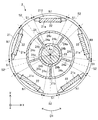
- ⁇ Rotor 2> 3 and 4 are cross-sectional views schematically showing the structure of the rotor 2.
- “N” shown in FIG. 3 indicates the N pole of the rotor 2 (specifically, the N pole that functions with respect to the stator 3), and “S” indicates the S pole of the rotor 2 (specifically, the S pole that functions with respect to the stator 3).
- the S pole) that functions with respect to the stator 3 is shown.
- the rotor 2 includes a rotor core 21, a plurality of permanent magnets 22, a shaft 23, and a non-magnetic member 24.
- the rotor 2 is rotatably arranged inside the stator 3. Specifically, the rotor 2 is arranged inside the stator 3 so that each permanent magnet 22 faces the stator 3.
- the axis of rotation of the rotor 2 coincides with the axis Ax.
- An air gap is provided between the rotor core 21 and the stator 3.
- the rotor core 21 is composed of a plurality of cores 210 stacked in the axial direction.
- the rotor core 21 (that is, the plurality of cores 210) is fixed to the non-magnetic member 24.
- the shaft 23 is rotatably held by bearings 7a and 7b. When the motor 1 is driven, the rotor core 21 and the non-magnetic member 24 rotate together with the shaft 23.
- the rotor core 21 may be longer than the stator core 31.
- the magnetic flux from the rotor 2 (specifically, each permanent magnet 22) efficiently flows into the stator core 31.
- the rotor core 21 (that is, a plurality of cores 210) has at least one magnet insertion hole 21a and a shaft insertion hole 21b.
- the rotor core 21 has a plurality of magnet insertion holes 21a, and at least one permanent magnet 22 is arranged in each magnet insertion hole 21a.
- the rotor core 21 is composed of, for example, a plurality of electromagnetic steel sheets.
- each of the plurality of cores 210 is an electromagnetic steel plate.
- the plurality of cores 210 may include cores other than the electrical steel sheet.
- the rotor core 21 may be composed of a plurality of iron cores having a predetermined shape, or may be composed of a mixture of a soft magnetic material and a resin.
- Each core 210 of the rotor core 21 has a thickness of, for example, 0.2 mm to 0.5 mm.
- the cores 210 of the rotor core 21 are laminated in the axial direction.
- the plurality of magnet insertion holes 21a are formed at equal intervals in the circumferential direction of the rotor core 21. In this embodiment, five magnet insertion holes 21a are provided in the rotor core 21.
- the shaft insertion hole 21b is provided in the central portion of the rotor core 21.
- the shaft insertion hole 21b penetrates the rotor core 21 in the axial direction.
- the shaft 23 is arranged in the shaft insertion hole 21b.
- Rotor 2 is a sequential pole type rotor. That is, the rotor 2 is a second magnetic pole formed by a first magnetic pole formed by each permanent magnet 22 and a part of the rotor core 21 adjacent to each magnet insertion hole 21a in the circumferential direction of the rotor core 21. It has a magnetic pole. That is, the second magnetic pole is a pseudo magnetic pole formed by a part of the rotor core 21 between two magnet insertion holes 21a adjacent to each other.
- the rotor 2 has a plurality of first magnetic pole regions N1 and a plurality of second magnetic pole regions S1.
- Each first magnetic pole region N1 is a region between two straight lines passing through both ends of one magnet insertion hole 21a and the rotation center of the rotor 2 in the xy plane.
- each second magnetic pole region S1 is a region in the xy plane between one end of each of two magnet insertion holes 21a adjacent to each other and two straight lines passing through the rotation center of the rotor 2. This is a region adjacent to the magnetic pole region N1. That is, each first magnetic pole region N1 is a region including a magnet insertion hole 21a and a permanent magnet 22, and each second magnetic pole region S1 is a region not including a magnet insertion hole 21a and a permanent magnet 22.
- Each permanent magnet 22 forms an N pole as the first magnetic pole of the rotor 2.
- a part of the rotor core 21 adjacent to each magnet insertion hole 21a in the circumferential direction of the rotor core 21 forms an S pole as a second magnetic pole which is a pseudo magnetic pole of the rotor 2.
- each first magnetic pole region N1 functions as a first magnetic pole (in the present embodiment, a magnetic pole acting as an N pole with respect to the stator 3)
- each second magnetic pole region S1 is a second magnetic pole region S1. It functions as a magnetic pole of 2 (in this embodiment, a pseudo magnetic pole that acts as an S pole with respect to the stator 3).
- each first magnetic pole region N1 functions as a first polarity
- each second magnetic pole region S1 functions as a second polarity different from the first polarity.
- the number of permanent magnets 22 is half of the number n of magnetic poles of the rotor 2 (n is an even number of 4 or more).
- the number n of the magnetic poles of the rotor 2 is the total number of the magnetic poles that function as N poles with respect to the stator 3 and the number of magnetic poles that function as S poles with respect to the stator 3.
- the shaft 23 is fixed to the rotor core 21 by a non-magnetic member 24.
- At least one permanent magnet 22 is arranged in each magnet insertion hole 21a.
- one permanent magnet 22 is arranged in each magnet insertion hole 21a.
- Each permanent magnet 22 is, for example, a flat plate-shaped permanent magnet.
- Each permanent magnet 22 is a rare earth magnet containing, for example, neodymium or samarium.
- the permanent magnet 22 may be a ferrite magnet containing iron.
- the type of the permanent magnet 22 is not limited to the example of the present embodiment, and the permanent magnet 22 may be formed of another material.
- the permanent magnets 22 in each magnet insertion hole 21a are magnetized in the radial direction, whereby the magnetic flux from each permanent magnet 22 flows into the stator 3.
- the non-magnetic member 24 is arranged in the shaft insertion hole 21b.
- the non-magnetic member 24 connects the shaft 23 to the rotor core 21.
- the non-magnetic member 24 includes, for example, austenite-based stainless steel, aluminum, unsaturated polyester resin (Bulk Molding Compound: BMC), polybutylene terephthalate (PBT), polyphenylene sulfide (Polyphenylene sulfide: PPS), liquid crystal polymer, and liquid crystal polymer. : LCP), made of non-magnetic materials such as polyethylene terephthalate (PET).
- BMC unsaturated polyester resin
- PBT polybutylene terephthalate
- PPS polyphenylene sulfide
- LCP made of non-magnetic materials such as polyethylene terephthalate (PET).
- the non-magnetic member 24 is, for example, a resin.
- the non-magnetic member 24 is made of, for example, a non-magnetic resin such as unsaturated polyester resin (BMC), polybutylene terephthalate (PBT), polyphenylene sulfide (PPS), liquid crystal polymer (LCP), or polyethylene terephthalate (PET). ing.
- BMC unsaturated polyester resin
- PBT polybutylene terephthalate
- PPS polyphenylene sulfide
- LCP liquid crystal polymer
- PET polyethylene terephthalate
- the non-magnetic member 24 has a coefficient of linear expansion larger than the coefficient of linear expansion of the rotor core 21.
- An example of the coefficient of linear expansion is as follows. Electrical steel: 1.08x10 -5 (1 / degC) Austenitic Stainless: 1.63x10 -5 (1 / degC) Aluminum: 2.36x10 -5 (1 / degC) BMC (unsaturated polyester resin): 1.5x10 -5 (1 / degC ) ⁇ 3.0x10 -5 (1 / degC) PBT (polybutylene terephthalate): 2x10 -5 (1 / degC ) ⁇ 9x10 -5 (1 / degC) PPS (polyphenylene sulfide): 4.9x10 -5 (1 / degC ) PET (polyethylene terephthalate): 6.5x10 -5 (1 / degC )
- the non-magnetic member 24 has an elastic modulus smaller than that of the rotor core 21.
- An example of the elastic modulus is as follows. Electrical steel sheet: 230 MPa Austenitic stainless steel: 197 MPa Aluminum: 72MPa BMC (unsaturated polyester resin): 140 MPa PBT (polybutylene terephthalate): 80 MPa PPS (polyphenylene sulfide): 110 MPa PET (polyethylene terephthalate): 100 MPa
- the non-magnetic member 24 has at least one beam 24a extending from the shaft 23 to the second magnetic pole region S1.
- the non-magnetic member 24 has a plurality of beams 24a (specifically, five beams 24a).
- the five beams 24a extend radially from the shaft 23.
- the beam extending from the shaft 23 to the first magnetic pole region N1 does not exist in the rotor 2. That is, the beam in contact with the rotor core 21 in the first magnetic pole region N1 does not exist in the rotor 2.
- Each beam 24a may be located between one end of each of two magnet insertion holes 21a adjacent to each other and two straight lines passing through the rotation center of the rotor 2 in the xy plane. That is, each beam 24a may be located in the second magnetic pole region S1. In the example shown in FIGS. 3 and 4, in the xy plane, each beam 24a is located on a straight line S2 passing through the center of the second magnetic pole region S1 and the rotation center of the rotor 2. Each straight line S2 is a magnetic pole center line passing through the center of the second magnetic pole.
- the non-magnetic member 24 may further have at least one shaft cover portion 24b covering the outer peripheral surface of the shaft 23 and at least one core cover portion 24c covering the inner peripheral surface of the rotor core 21.
- the shaft cover portion 24b and the core cover portion 24c are connected to the beam 24a.
- the region surrounded by the beam 24a, the shaft cover portion 24b, and the core cover portion 24c is a gap.
- the rotor 2 does not have to have the core cover portion 24c. Even in this case, the non-magnetic member 24 (specifically, the beam 24a) comes into contact with the rotor core 21 in the second magnetic pole region S1.
- the rotor core 21, the shaft 23, and the non-magnetic member 24 are fixed by, for example, integral molding using a mold.
- the material (for example, resin) of the non-magnetic member 24 is formed by a mold in which the rotor core 21 and the shaft 23 are arranged.
- the shaft 23 is fixed to the non-magnetic member 24 together with the rotor core 21.
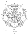
- FIG. 5 is a diagram showing another example of the rotor 2.
- the rotor core 21 has at least one protrusion 21c that projects toward the shaft 23.
- the rotor core 21 has five protrusions 21c.
- Each protrusion 21c is formed on the inner peripheral surface of the rotor core 21.
- the core cover portion 24c covers the protruding portion 21c.
- the rotor core 21 may have at least one void 21d.
- the rotor core 21 has five voids 21d.
- Each gap 21d is provided between the magnet insertion hole 21a and the protrusion 21c, and faces the protrusion 21c.
- the minimum width W1 of the protruding portion 21c is 1 times or more and 2 times or less the thickness of the core 210.
- the minimum width W1 of the protrusion 21c may be 1 time or more and 4 times or less the thickness of the core 210.
- the thickness of the core 210 is, for example, 0.35 mm
- the minimum width W1 of the protruding portion 21c is, for example, 0.60 mm.
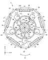
- FIG. 6 is a diagram showing still another example of the rotor 2.
- the rotor core 21 has at least one void 21d.
- Each gap 21d faces the protrusion 21c, and each beam 24a is located on a straight line passing through the gap 21d and the rotation center of the rotor 2.
- the straight line passing through the gap 21d and the rotation center of the rotor 2 is the straight line S2. Therefore, each beam 24a and each gap 21d are located on the straight line S2.
- the minimum width W1 of the protruding portion 21c can have the same configuration as that of the first modification.
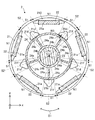
- FIG. 7 is a diagram showing still another example of the rotor 2.
- the rotor core 21 has at least one recess 21e recessed toward the outer peripheral surface of the rotor core 21.
- the rotor core 21 has five recesses 21e.
- Each recess 21e is formed on the inner peripheral surface of the rotor core 21.
- the core cover portion 24c covers the recess 21e.
- the rotor core 21 may have at least one void 21d.
- the rotor core 21 has five voids 21d.
- Each gap 21d is provided between the magnet insertion hole 21a and the recess 21e, and faces the recess 21e.
- the minimum width W2 of the recess 21e is 1 times or more and 2 times or less the thickness of the core 210.
- the minimum width W2 of the recess 21e may be 1 times or more and 4 times or less the thickness of the core 210.
- the thickness of the core 210 is, for example, 0.35 mm
- the minimum width W2 of the recess 21e is, for example, 0.60 mm.
- each gap 21d faces the recess 21e, and each beam 24a is located on a straight line passing through the gap 21d and the rotation center of the rotor 2.
- the straight line passing through the gap 21d and the rotation center of the rotor 2 is the straight line S2. Therefore, each beam 24a and each gap 21d are located on the straight line S2.
- FIG. 8 is a diagram showing still another example of the rotor 2.
- the rotor core 21 has at least one gap 21d and at least one extending portion 21f facing the gap 21d.
- the rotor core 21 has five voids 21d and five extending portions 21f.
- Each extending portion 21f extends straight in the xy plane.
- each extending portion 21f faces the beam 24a in the xy plane and is orthogonal to the facing beam 24a.
- Each extending portion 21f is formed on the inner peripheral surface of the rotor core 21. In this case, the core cover portion 24c covers the extending portion 21f.
- each void 21d may be a triangle. In this case, in the xy plane, one side of each gap 21d is parallel to the extending portion 21f.
- the minimum width W3 of the extending portion 21f is 1 times or more and 2 times or less the thickness of the core 210. In the xy plane, the minimum width W3 of the extending portion 21f may be 1 time or more and 4 times or less the thickness of the core 210. In the modified example 4, the thickness of the core 210 is, for example, 0.35 mm, and the minimum width W3 of the extending portion 21f is, for example, 0.60 mm.
- FIG. 9 is a cross-sectional view showing a rotor 2a as a comparative example.
- each beam 24a extends from the shaft 23 to the first magnetic pole region N1.
- the stress concentrates on the rotor core 21 between the beam 24a and the permanent magnet 22.
- the non-magnetic member 24 has a linear expansion coefficient larger than the linear expansion coefficient of the rotor core 21, the stress due to the expansion of the beam 24a tends to be concentrated in the region facing the magnet insertion hole 21a.
- the magnet insertion hole 21a may be deformed, and the permanent magnet 22 arranged in the magnet insertion hole 21a may be damaged.
- FIG. 10 is a diagram showing stress generated in the rotor core 21 when the beam 24a expands in the rotor 2a as a comparative example.
- FIG. 10 a partial region of the rotor 2a is shown.
- FIG. 11 is a diagram showing the displacement of the rotor core 21 when the beam 24a expands in the rotor 2a as a comparative example.
- the region shown in FIG. 10 is shown.
- the stress due to the expansion of the beam 24a is concentrated in the region facing the magnet insertion hole 21a.
- the displacement of the region facing the magnet insertion hole 21a is large.
- the region between the beam 24a and the magnet insertion hole 21a is deformed outward in the radial direction.
- the inner wall of the magnet insertion hole 21a may come into strong contact with the permanent magnet 22 and the permanent magnet 22 may be damaged.
- FIG. 12 is a diagram showing stress generated in the rotor core 21 when the beam 24a expands in the rotor 2 according to the first embodiment.
- FIG. 12 a part area of the rotor 2 is shown.
- FIG. 13 is a diagram showing the displacement of the rotor core 21 when the beam 24a expands in the rotor 2 according to the first embodiment.
- the region shown in FIG. 12 is shown.
- each beam 24a extends from the shaft 23 to the second magnetic pole region S1.
- the beam extending from the shaft 23 to the first magnetic pole region N1 does not exist in the rotor 2.
- the beam 24a when the beam 24a is located on the straight line S2 passing through the center of the second magnetic pole region S1 and the rotation center of the rotor 2 in the xy plane, the beam 24a inserts two magnets. It is provided at a position evenly separated from the hole 21a. In this case, even when the beam 24a expands due to a temperature change, deformation of the region between the beam 24a and the magnet insertion hole 21a can be effectively prevented. As a result, deformation of the magnet insertion hole 21a can be prevented, and damage to the permanent magnet 22 arranged in the magnet insertion hole 21a can be effectively prevented.
- the non-magnetic member 24 has an elastic modulus smaller than the elastic modulus of the rotor core 21, the stress due to the expansion of the beam 24a is reduced, and the deformation of the region between the beam 24a and the magnet insertion hole 21a can be effectively prevented.
- the non-magnetic member 24 is made of resin, the stress due to the expansion of the beam 24a is reduced as compared with metal. As a result, deformation of the magnet insertion hole 21a can be prevented, and damage to the permanent magnet 22 arranged in the magnet insertion hole 21a can be effectively prevented.
- the rotor 2 can be molded by integral molding using a mold. Therefore, the manufacturing process of the rotor 2 such as the fixing process of the shaft 23 can be simplified as compared with the methods such as press fitting, caulking, and shrink fitting.
- the core cover portion 24c covers the protruding portion 21c. Therefore, it is possible to prevent the shaft 23 connected to the non-magnetic member 24 from being displaced in the circumferential direction with respect to the rotor core 21.
- the minimum width W1 of the protruding portion 21c is 1 times or more and 4 times or less the thickness of the core 210, it is easy to process by the punching process, and the protruding portion 21c is easily deformed in the radial direction.
- the expansion of the beam 24a expands, the stress due to the expansion of the beam 24a is absorbed by the deformation of the protrusion 21c. Therefore, even when the beam 24a expands due to a temperature change, the magnet insertion hole 21a can be prevented from being deformed, and the permanent magnet 22 arranged in the magnet insertion hole 21a can be prevented from being damaged.
- the minimum width W1 of the protruding portion 21c is 1 times or more and 2 times or less the thickness of the core 210, the deformation of the magnet insertion hole 21a is effectively prevented, and the permanent magnet 22 arranged in the magnet insertion hole 21a is damaged. Can be effectively prevented.
- the core cover portion 24c covers the recess 21e. Therefore, it is possible to prevent the shaft 23 connected to the non-magnetic member 24 from being displaced in the circumferential direction with respect to the rotor core 21.
- FIG. 14 is a diagram showing stress generated in the rotor core 21 when the beam 24a expands in the rotor 2 in the modified example 3.
- FIG. 14 a partial region of the rotor 2 is shown.
- FIG. 15 is a diagram showing the displacement of the rotor core 21 when the beam 24a is expanded in the rotor 2 in the modified example 3.
- the region shown in FIG. 14 is shown.
- the minimum width W2 of the recess 21e is 1 times or more and 4 times or less the thickness of the core 210, the recess 21e is easily deformed in the radial direction.
- the recess 21e when the minimum width W2 of the recess 21e is 1 times or more and 2 times or less the thickness of the core 210, the recess 21e is easily deformed in the radial direction.
- the stress due to the expansion of the beam 24a is absorbed by the deformation of the recess 21e, as shown in FIGS. 14 and 15. Therefore, even when the beam 24a expands due to a temperature change, the magnet insertion hole 21a can be prevented from being deformed, and the permanent magnet 22 arranged in the magnet insertion hole 21a can be prevented from being damaged.
- the core cover portion 24c covers the extending portion 21f. Even in this case, similarly to the first to third modifications, it is possible to prevent the shaft 23 connected to the non-magnetic member 24 from being displaced in the circumferential direction with respect to the rotor core 21. Further, in the xy plane, when the minimum width W3 of the extending portion 21f is 1 times or more and 4 times or less the thickness of the core 210, it is easy to process by the punching process, and the extending portion 21f is deformed in the radial direction. Cheap. When the expansion of the beam 24a expands, the stress due to the expansion of the beam 24a is absorbed by the deformation of the extending portion 21f.
- the magnet insertion hole 21a can be prevented from being deformed, and the permanent magnet 22 arranged in the magnet insertion hole 21a can be prevented from being damaged.
- the minimum width W3 of the extending portion 21f is 1 times or more and 2 times or less the thickness of the core 210, the deformation of the magnet insertion hole 21a is effectively prevented, and the permanent magnet 22 arranged in the magnet insertion hole 21a Damage can be effectively prevented.
- FIG. 16 is a diagram schematically showing the structure of the fan 60 according to the second embodiment.
- the fan 60 has a blade 61 and an electric motor 62.
- the fan 60 is also referred to as a blower.
- the electric motor 62 is the electric motor 1 according to the first embodiment.
- the blades 61 are fixed to the shaft of the motor 62.
- the electric motor 62 drives the blades 61. Specifically, the electric motor 62 rotates the blades 61. When the motor 62 is driven, the blades 61 rotate to generate an air flow. As a result, the fan 60 can blow air.
- the electric motor 1 described in the first embodiment is applied to the electric motor 62, the same advantages as those described in the first embodiment can be obtained. Further, it is possible to prevent a decrease in the efficiency of the fan 60.
- Embodiment 3 The air conditioner 50 (also referred to as a refrigerating air conditioner or a refrigerating cycle device) according to the third embodiment will be described.
- FIG. 17 is a diagram schematically showing the configuration of the air conditioner 50 according to the third embodiment.
- FIG. 18 is a diagram schematically showing the main components in the outdoor unit 53 as a blower of the air conditioner 50.
- the air conditioner 50 includes an indoor unit 51 as a blower (first blower), a refrigerant pipe 52, and an outdoor unit 53 as a blower (second blower) connected to the indoor unit 51. And.
- the outdoor unit 53 is connected to the indoor unit 51 through a refrigerant pipe 52.
- the indoor unit 51 includes an electric motor 51a (for example, the electric motor 1 according to the first embodiment), a blower portion 51b that blows air by being driven by the electric motor 51a, and a housing 51c that covers the electric motor 51a and the blower portion 51b. ..
- the blower portion 51b has, for example, blades 51d driven by an electric motor 51a.
- the blades 51d are fixed to the shaft of the motor 51a and generate an air flow.
- the outdoor unit 53 includes an electric motor 53a (for example, the electric motor 1 according to the first embodiment), a blower 53b, a compressor 54, a heat exchanger (not shown), a blower 53b, a compressor 54, and heat. It has a housing 53c that covers the exchanger.
- the blower unit 53b blows air by being driven by the electric motor 53a.
- the blower portion 53b has, for example, a blade 53d driven by an electric motor 53a.
- the blades 53d are fixed to the shaft of the motor 53a and generate an air flow.
- the compressor 54 includes an electric motor 54a (for example, the electric motor 1 according to the first embodiment), a compression mechanism 54b (for example, a refrigerant circuit) driven by the electric motor 54a, and a housing 54c that covers the electric motor 54a and the compression mechanism 54b.
- an electric motor 54a for example, the electric motor 1 according to the first embodiment
- a compression mechanism 54b for example, a refrigerant circuit driven by the electric motor 54a
- a housing 54c that covers the electric motor 54a and the compression mechanism 54b.
- the indoor unit 51 and the outdoor unit 53 has the motor 1 described in the first embodiment. That is, the indoor unit 51, the outdoor unit 53, or both of them have the electric motor 1 described in the first embodiment.
- the motor 1 described in the first embodiment is applied to at least one of the motors 51a and 53a. That is, the motor 1 described in the first embodiment is applied to the indoor unit 51, the outdoor unit 53, or both of them.
- the motor 1 described in the first embodiment may be applied to the motor 54a of the compressor 54.
- the air conditioner 50 can perform air conditioning such as a cooling operation in which cold air is blown from the indoor unit 51 and a heating operation in which warm air is blown, for example.
- the motor 51a is a drive source for driving the blower portion 51b.
- the blower portion 51b can blow the adjusted air.
- the electric motor 53a is fixed to the housing 53c of the outdoor unit 53 by, for example, a screw 53e.
- the same advantages as those described in the first embodiment can be obtained. Can be done. As a result, it is possible to prevent a decrease in the efficiency of the air conditioner 50.
- the motor 1 according to the first embodiment when used as the drive source of the blower (for example, the indoor unit 51), the same advantages as those described in the first embodiment can be obtained. As a result, it is possible to prevent a decrease in the efficiency of the blower.
- the blower having the motor 1 according to the first embodiment and the blades (for example, blades 51d or 53d) driven by the motor 1 can be used alone as a blower device. This blower can be applied to equipment other than the air conditioner 50.
- the motor 1 according to the first embodiment is used as the drive source of the compressor 54, the same advantages as those described in the first embodiment can be obtained. As a result, it is possible to prevent a decrease in the efficiency of the compressor 54.
- the electric motor 1 described in the first embodiment can be mounted on a device having a drive source, such as a ventilation fan, a home electric appliance, or a machine tool, in addition to the air conditioner 50.
- a drive source such as a ventilation fan, a home electric appliance, or a machine tool, in addition to the air conditioner 50.
Landscapes
- Engineering & Computer Science (AREA)
- Power Engineering (AREA)
- Permanent Field Magnets Of Synchronous Machinery (AREA)
- Iron Core Of Rotating Electric Machines (AREA)
Priority Applications (5)
| Application Number | Priority Date | Filing Date | Title |
|---|---|---|---|
| CN202080096966.3A CN115136460A (zh) | 2020-02-27 | 2020-02-27 | 交替极型转子、电动机、风扇及空气调节机 |
| JP2022502707A JP7259128B2 (ja) | 2020-02-27 | 2020-02-27 | コンシクエントポール型ロータ、電動機、ファン、及び空気調和機 |
| PCT/JP2020/008009 WO2021171474A1 (ja) | 2020-02-27 | 2020-02-27 | コンシクエントポール型ロータ、電動機、ファン、及び空気調和機 |
| US17/792,006 US20230039239A1 (en) | 2020-02-27 | 2020-02-27 | Consequent pole rotor, motor, fan, and air conditioner |
| JP2023060716A JP7450783B2 (ja) | 2020-02-27 | 2023-04-04 | コンシクエントポール型ロータ、電動機、ファン、及び空気調和機 |
Applications Claiming Priority (1)
| Application Number | Priority Date | Filing Date | Title |
|---|---|---|---|
| PCT/JP2020/008009 WO2021171474A1 (ja) | 2020-02-27 | 2020-02-27 | コンシクエントポール型ロータ、電動機、ファン、及び空気調和機 |
Publications (1)
| Publication Number | Publication Date |
|---|---|
| WO2021171474A1 true WO2021171474A1 (ja) | 2021-09-02 |
Family
ID=77490046
Family Applications (1)
| Application Number | Title | Priority Date | Filing Date |
|---|---|---|---|
| PCT/JP2020/008009 Ceased WO2021171474A1 (ja) | 2020-02-27 | 2020-02-27 | コンシクエントポール型ロータ、電動機、ファン、及び空気調和機 |
Country Status (4)
| Country | Link |
|---|---|
| US (1) | US20230039239A1 (https=) |
| JP (2) | JP7259128B2 (https=) |
| CN (1) | CN115136460A (https=) |
| WO (1) | WO2021171474A1 (https=) |
Cited By (1)
| Publication number | Priority date | Publication date | Assignee | Title |
|---|---|---|---|---|
| JPWO2023148953A1 (https=) * | 2022-02-07 | 2023-08-10 |
Citations (4)
| Publication number | Priority date | Publication date | Assignee | Title |
|---|---|---|---|---|
| WO2018011979A1 (ja) * | 2016-07-15 | 2018-01-18 | 三菱電機株式会社 | コンシクエントポール型ロータ、電動機、空気調和機、及びコンシクエントポール型ロータの製造方法 |
| WO2018134988A1 (ja) * | 2017-01-23 | 2018-07-26 | 三菱電機株式会社 | 回転子、電動機、空気調和装置、および回転子の製造方法 |
| WO2019026273A1 (ja) * | 2017-08-04 | 2019-02-07 | 三菱電機株式会社 | 回転子、電動機、送風機、空気調和装置および回転子の製造方法 |
| WO2020003341A1 (ja) * | 2018-06-25 | 2020-01-02 | 三菱電機株式会社 | ロータ、電動機、送風機および空気調和装置 |
Family Cites Families (11)
| Publication number | Priority date | Publication date | Assignee | Title |
|---|---|---|---|---|
| JP5474404B2 (ja) * | 2009-05-20 | 2014-04-16 | アスモ株式会社 | ロータ及びモータ |
| JP4881418B2 (ja) * | 2009-10-09 | 2012-02-22 | 本田技研工業株式会社 | 回転電機 |
| US9099905B2 (en) * | 2012-10-15 | 2015-08-04 | Regal Beloit America, Inc. | Radially embedded permanent magnet rotor and methods thereof |
| JP5787184B2 (ja) * | 2012-12-05 | 2015-09-30 | 株式会社デンソー | 回転子、および、これを用いた回転電機 |
| JP5796569B2 (ja) * | 2012-12-28 | 2015-10-21 | 株式会社デンソー | 回転子、および、これを用いた回転電機 |
| WO2017026065A1 (ja) * | 2015-08-12 | 2017-02-16 | 三菱電機株式会社 | 電動機及び空気調和機 |
| US11031831B2 (en) * | 2016-04-21 | 2021-06-08 | Mitsubishi Electric Corporation | Electric motor and air conditioner |
| CN105762958A (zh) * | 2016-05-06 | 2016-07-13 | 浙江希尔富电气有限公司 | 一种用于无刷电机的转子铁芯 |
| CN110326190B (zh) * | 2017-03-03 | 2022-08-19 | 三菱电机株式会社 | 转子、电动机、压缩机及送风机 |
| CN109768647B (zh) * | 2019-03-21 | 2024-12-17 | 中山大洋电机股份有限公司 | 一种永磁转子组件及电机 |
| US20220376569A1 (en) * | 2020-02-12 | 2022-11-24 | Mitsubishi Electric Corporation | Rotor, motor, fan, and air conditioner |
-
2020
- 2020-02-27 WO PCT/JP2020/008009 patent/WO2021171474A1/ja not_active Ceased
- 2020-02-27 CN CN202080096966.3A patent/CN115136460A/zh active Pending
- 2020-02-27 US US17/792,006 patent/US20230039239A1/en not_active Abandoned
- 2020-02-27 JP JP2022502707A patent/JP7259128B2/ja active Active
-
2023
- 2023-04-04 JP JP2023060716A patent/JP7450783B2/ja active Active
Patent Citations (4)
| Publication number | Priority date | Publication date | Assignee | Title |
|---|---|---|---|---|
| WO2018011979A1 (ja) * | 2016-07-15 | 2018-01-18 | 三菱電機株式会社 | コンシクエントポール型ロータ、電動機、空気調和機、及びコンシクエントポール型ロータの製造方法 |
| WO2018134988A1 (ja) * | 2017-01-23 | 2018-07-26 | 三菱電機株式会社 | 回転子、電動機、空気調和装置、および回転子の製造方法 |
| WO2019026273A1 (ja) * | 2017-08-04 | 2019-02-07 | 三菱電機株式会社 | 回転子、電動機、送風機、空気調和装置および回転子の製造方法 |
| WO2020003341A1 (ja) * | 2018-06-25 | 2020-01-02 | 三菱電機株式会社 | ロータ、電動機、送風機および空気調和装置 |
Cited By (1)
| Publication number | Priority date | Publication date | Assignee | Title |
|---|---|---|---|---|
| JPWO2023148953A1 (https=) * | 2022-02-07 | 2023-08-10 |
Also Published As
| Publication number | Publication date |
|---|---|
| JP7450783B2 (ja) | 2024-03-15 |
| CN115136460A (zh) | 2022-09-30 |
| US20230039239A1 (en) | 2023-02-09 |
| JP2023076591A (ja) | 2023-06-01 |
| JP7259128B2 (ja) | 2023-04-17 |
| JPWO2021171474A1 (https=) | 2021-09-02 |
Similar Documents
| Publication | Publication Date | Title |
|---|---|---|
| JP6964672B2 (ja) | ロータ、電動機、送風機および空気調和装置 | |
| JPWO2020261420A1 (ja) | 回転子、電動機、送風機、空気調和機、及び回転子の製造方法 | |
| WO2020129123A1 (ja) | 回転子、電動機、送風機、及び空気調和機、並びに回転子の製造方法 | |
| JP6964796B2 (ja) | 回転子、コンシクエントポール型回転子、電動機、送風機、冷凍空調装置、回転子の製造方法、及びコンシクエントポール型回転子の製造方法 | |
| WO2021024338A1 (ja) | 電動機およびそれを用いた空気調和機 | |
| JP2023060060A (ja) | ロータ、電動機、ファン、及び空気調和機 | |
| JP7450783B2 (ja) | コンシクエントポール型ロータ、電動機、ファン、及び空気調和機 | |
| JP7098047B2 (ja) | モータ、ファン、および空気調和機 | |
| JP7559044B2 (ja) | 電動機、ファン、及び空気調和機 | |
| JP7321393B2 (ja) | 電動機、ファン、及び空気調和機 | |
| JP7026805B2 (ja) | ステータ、モータ、ファン、及び空気調和機並びにステータの製造方法 | |
| CN118613994A (zh) | 电动机和空调机 | |
| JP7063916B2 (ja) | ロータ、電動機、圧縮機、空気調和機、及びロータの製造方法 | |
| JP7607790B2 (ja) | ロータ、電動機、送風機および空気調和装置 | |
| JPWO2021019592A1 (ja) | 電動機、送風機、空気調和装置および電動機の製造方法 | |
| JPWO2020026403A1 (ja) | ロータ、モータ、ファン、空気調和装置、及びロータの製造方法 | |
| JPWO2020026408A1 (ja) | モータ、ファン、空気調和装置、及びモータの製造方法 | |
| WO2022180708A1 (ja) | ステータ、電動機、及び空気調和機 | |
| JPWO2020026406A1 (ja) | ロータ、モータ、ファン、空気調和装置、及びロータの製造方法 |
Legal Events
| Date | Code | Title | Description |
|---|---|---|---|
| 121 | Ep: the epo has been informed by wipo that ep was designated in this application |
Ref document number: 20921783 Country of ref document: EP Kind code of ref document: A1 |
|
| WWE | Wipo information: entry into national phase |
Ref document number: 2022502707 Country of ref document: JP |
|
| NENP | Non-entry into the national phase |
Ref country code: DE |
|
| 122 | Ep: pct application non-entry in european phase |
Ref document number: 20921783 Country of ref document: EP Kind code of ref document: A1 |