WO2021166532A1 - 灯具ユニット及び車両用灯具 - Google Patents
灯具ユニット及び車両用灯具 Download PDFInfo
- Publication number
- WO2021166532A1 WO2021166532A1 PCT/JP2021/001904 JP2021001904W WO2021166532A1 WO 2021166532 A1 WO2021166532 A1 WO 2021166532A1 JP 2021001904 W JP2021001904 W JP 2021001904W WO 2021166532 A1 WO2021166532 A1 WO 2021166532A1
- Authority
- WO
- WIPO (PCT)
- Prior art keywords
- light emitting
- emitting element
- lens
- light
- lamp
- Prior art date
- Legal status (The legal status is an assumption and is not a legal conclusion. Google has not performed a legal analysis and makes no representation as to the accuracy of the status listed.)
- Ceased
Links
Images










Classifications
-
- F—MECHANICAL ENGINEERING; LIGHTING; HEATING; WEAPONS; BLASTING
- F21—LIGHTING
- F21S—NON-PORTABLE LIGHTING DEVICES; SYSTEMS THEREOF; VEHICLE LIGHTING DEVICES SPECIALLY ADAPTED FOR VEHICLE EXTERIORS
- F21S41/00—Illuminating devices specially adapted for vehicle exteriors, e.g. headlamps
- F21S41/10—Illuminating devices specially adapted for vehicle exteriors, e.g. headlamps characterised by the light source
- F21S41/14—Illuminating devices specially adapted for vehicle exteriors, e.g. headlamps characterised by the light source characterised by the type of light source
- F21S41/141—Light emitting diodes [LED]
- F21S41/143—Light emitting diodes [LED] the main emission direction of the LED being parallel to the optical axis of the illuminating device
-
- F—MECHANICAL ENGINEERING; LIGHTING; HEATING; WEAPONS; BLASTING
- F21—LIGHTING
- F21S—NON-PORTABLE LIGHTING DEVICES; SYSTEMS THEREOF; VEHICLE LIGHTING DEVICES SPECIALLY ADAPTED FOR VEHICLE EXTERIORS
- F21S41/00—Illuminating devices specially adapted for vehicle exteriors, e.g. headlamps
- F21S41/20—Illuminating devices specially adapted for vehicle exteriors, e.g. headlamps characterised by refractors, transparent cover plates, light guides or filters
- F21S41/24—Light guides
-
- F—MECHANICAL ENGINEERING; LIGHTING; HEATING; WEAPONS; BLASTING
- F21—LIGHTING
- F21S—NON-PORTABLE LIGHTING DEVICES; SYSTEMS THEREOF; VEHICLE LIGHTING DEVICES SPECIALLY ADAPTED FOR VEHICLE EXTERIORS
- F21S41/00—Illuminating devices specially adapted for vehicle exteriors, e.g. headlamps
- F21S41/20—Illuminating devices specially adapted for vehicle exteriors, e.g. headlamps characterised by refractors, transparent cover plates, light guides or filters
- F21S41/25—Projection lenses
- F21S41/265—Composite lenses; Lenses with a patch-like shape
-
- F—MECHANICAL ENGINEERING; LIGHTING; HEATING; WEAPONS; BLASTING
- F21—LIGHTING
- F21S—NON-PORTABLE LIGHTING DEVICES; SYSTEMS THEREOF; VEHICLE LIGHTING DEVICES SPECIALLY ADAPTED FOR VEHICLE EXTERIORS
- F21S41/00—Illuminating devices specially adapted for vehicle exteriors, e.g. headlamps
- F21S41/20—Illuminating devices specially adapted for vehicle exteriors, e.g. headlamps characterised by refractors, transparent cover plates, light guides or filters
- F21S41/29—Attachment thereof
-
- F—MECHANICAL ENGINEERING; LIGHTING; HEATING; WEAPONS; BLASTING
- F21—LIGHTING
- F21S—NON-PORTABLE LIGHTING DEVICES; SYSTEMS THEREOF; VEHICLE LIGHTING DEVICES SPECIALLY ADAPTED FOR VEHICLE EXTERIORS
- F21S41/00—Illuminating devices specially adapted for vehicle exteriors, e.g. headlamps
- F21S41/60—Illuminating devices specially adapted for vehicle exteriors, e.g. headlamps characterised by a variable light distribution
- F21S41/63—Illuminating devices specially adapted for vehicle exteriors, e.g. headlamps characterised by a variable light distribution by acting on refractors, filters or transparent cover plates
-
- F—MECHANICAL ENGINEERING; LIGHTING; HEATING; WEAPONS; BLASTING
- F21—LIGHTING
- F21S—NON-PORTABLE LIGHTING DEVICES; SYSTEMS THEREOF; VEHICLE LIGHTING DEVICES SPECIALLY ADAPTED FOR VEHICLE EXTERIORS
- F21S41/00—Illuminating devices specially adapted for vehicle exteriors, e.g. headlamps
- F21S41/60—Illuminating devices specially adapted for vehicle exteriors, e.g. headlamps characterised by a variable light distribution
- F21S41/65—Illuminating devices specially adapted for vehicle exteriors, e.g. headlamps characterised by a variable light distribution by acting on light sources
- F21S41/657—Illuminating devices specially adapted for vehicle exteriors, e.g. headlamps characterised by a variable light distribution by acting on light sources by moving light sources
-
- F—MECHANICAL ENGINEERING; LIGHTING; HEATING; WEAPONS; BLASTING
- F21—LIGHTING
- F21S—NON-PORTABLE LIGHTING DEVICES; SYSTEMS THEREOF; VEHICLE LIGHTING DEVICES SPECIALLY ADAPTED FOR VEHICLE EXTERIORS
- F21S41/00—Illuminating devices specially adapted for vehicle exteriors, e.g. headlamps
- F21S41/60—Illuminating devices specially adapted for vehicle exteriors, e.g. headlamps characterised by a variable light distribution
- F21S41/65—Illuminating devices specially adapted for vehicle exteriors, e.g. headlamps characterised by a variable light distribution by acting on light sources
- F21S41/663—Illuminating devices specially adapted for vehicle exteriors, e.g. headlamps characterised by a variable light distribution by acting on light sources by switching light sources
-
- F—MECHANICAL ENGINEERING; LIGHTING; HEATING; WEAPONS; BLASTING
- F21—LIGHTING
- F21S—NON-PORTABLE LIGHTING DEVICES; SYSTEMS THEREOF; VEHICLE LIGHTING DEVICES SPECIALLY ADAPTED FOR VEHICLE EXTERIORS
- F21S45/00—Arrangements within vehicle lighting devices specially adapted for vehicle exteriors, for purposes other than emission or distribution of light
- F21S45/40—Cooling of lighting devices
- F21S45/47—Passive cooling, e.g. using fins, thermal conductive elements or openings
-
- F—MECHANICAL ENGINEERING; LIGHTING; HEATING; WEAPONS; BLASTING
- F21—LIGHTING
- F21V—FUNCTIONAL FEATURES OR DETAILS OF LIGHTING DEVICES OR SYSTEMS THEREOF; STRUCTURAL COMBINATIONS OF LIGHTING DEVICES WITH OTHER ARTICLES, NOT OTHERWISE PROVIDED FOR
- F21V17/00—Fastening of component parts of lighting devices, e.g. shades, globes, refractors, reflectors, filters, screens, grids or protective cages
-
- F—MECHANICAL ENGINEERING; LIGHTING; HEATING; WEAPONS; BLASTING
- F21—LIGHTING
- F21V—FUNCTIONAL FEATURES OR DETAILS OF LIGHTING DEVICES OR SYSTEMS THEREOF; STRUCTURAL COMBINATIONS OF LIGHTING DEVICES WITH OTHER ARTICLES, NOT OTHERWISE PROVIDED FOR
- F21V19/00—Fastening of light sources or lamp holders
-
- F—MECHANICAL ENGINEERING; LIGHTING; HEATING; WEAPONS; BLASTING
- F21—LIGHTING
- F21V—FUNCTIONAL FEATURES OR DETAILS OF LIGHTING DEVICES OR SYSTEMS THEREOF; STRUCTURAL COMBINATIONS OF LIGHTING DEVICES WITH OTHER ARTICLES, NOT OTHERWISE PROVIDED FOR
- F21V29/00—Protecting lighting devices from thermal damage; Cooling or heating arrangements specially adapted for lighting devices or systems
- F21V29/50—Cooling arrangements
- F21V29/502—Cooling arrangements characterised by the adaptation for cooling of specific components
- F21V29/503—Cooling arrangements characterised by the adaptation for cooling of specific components of light sources
-
- F—MECHANICAL ENGINEERING; LIGHTING; HEATING; WEAPONS; BLASTING
- F21—LIGHTING
- F21V—FUNCTIONAL FEATURES OR DETAILS OF LIGHTING DEVICES OR SYSTEMS THEREOF; STRUCTURAL COMBINATIONS OF LIGHTING DEVICES WITH OTHER ARTICLES, NOT OTHERWISE PROVIDED FOR
- F21V29/00—Protecting lighting devices from thermal damage; Cooling or heating arrangements specially adapted for lighting devices or systems
- F21V29/50—Cooling arrangements
- F21V29/70—Cooling arrangements characterised by passive heat-dissipating elements, e.g. heat-sinks
- F21V29/74—Cooling arrangements characterised by passive heat-dissipating elements, e.g. heat-sinks with fins or blades
- F21V29/76—Cooling arrangements characterised by passive heat-dissipating elements, e.g. heat-sinks with fins or blades with essentially identical parallel planar fins or blades, e.g. with comb-like cross-section
-
- F—MECHANICAL ENGINEERING; LIGHTING; HEATING; WEAPONS; BLASTING
- F21—LIGHTING
- F21V—FUNCTIONAL FEATURES OR DETAILS OF LIGHTING DEVICES OR SYSTEMS THEREOF; STRUCTURAL COMBINATIONS OF LIGHTING DEVICES WITH OTHER ARTICLES, NOT OTHERWISE PROVIDED FOR
- F21V5/00—Refractors for light sources
-
- F—MECHANICAL ENGINEERING; LIGHTING; HEATING; WEAPONS; BLASTING
- F21—LIGHTING
- F21W—INDEXING SCHEME ASSOCIATED WITH SUBCLASSES F21K, F21L, F21S and F21V, RELATING TO USES OR APPLICATIONS OF LIGHTING DEVICES OR SYSTEMS
- F21W2102/00—Exterior vehicle lighting devices for illuminating purposes
- F21W2102/10—Arrangement or contour of the emitted light
- F21W2102/13—Arrangement or contour of the emitted light for high-beam region or low-beam region
- F21W2102/135—Arrangement or contour of the emitted light for high-beam region or low-beam region the light having cut-off lines, i.e. clear borderlines between emitted regions and dark regions
-
- F—MECHANICAL ENGINEERING; LIGHTING; HEATING; WEAPONS; BLASTING
- F21—LIGHTING
- F21W—INDEXING SCHEME ASSOCIATED WITH SUBCLASSES F21K, F21L, F21S and F21V, RELATING TO USES OR APPLICATIONS OF LIGHTING DEVICES OR SYSTEMS
- F21W2102/00—Exterior vehicle lighting devices for illuminating purposes
- F21W2102/10—Arrangement or contour of the emitted light
- F21W2102/13—Arrangement or contour of the emitted light for high-beam region or low-beam region
- F21W2102/135—Arrangement or contour of the emitted light for high-beam region or low-beam region the light having cut-off lines, i.e. clear borderlines between emitted regions and dark regions
- F21W2102/155—Arrangement or contour of the emitted light for high-beam region or low-beam region the light having cut-off lines, i.e. clear borderlines between emitted regions and dark regions having inclined and horizontal cutoff lines
-
- F—MECHANICAL ENGINEERING; LIGHTING; HEATING; WEAPONS; BLASTING
- F21—LIGHTING
- F21Y—INDEXING SCHEME ASSOCIATED WITH SUBCLASSES F21K, F21L, F21S and F21V, RELATING TO THE FORM OR THE KIND OF THE LIGHT SOURCES OR OF THE COLOUR OF THE LIGHT EMITTED
- F21Y2115/00—Light-generating elements of semiconductor light sources
- F21Y2115/10—Light-emitting diodes [LED]
Definitions
- This disclosure relates to a lamp unit and a lamp for a vehicle on which the lamp unit is mounted.
- Patent Document 1 discloses a bracket connected to an aiming mechanism for adjusting the optical axis of a lamp unit provided in a vehicle lamp.
- the bracket disclosed in Patent Document 1 is formed in a frame shape in a front view, and is connected to a left-right direction aiming mechanism and a vertical direction aiming mechanism.
- the left-right direction aiming mechanism is configured to adjust the optical axis of the lamp unit in the left-right direction.
- the vertical aiming mechanism is configured to adjust the optical axis of the lamp unit in the vertical direction.
- Patent Document 2 describes an optical system (for example, a reflector or a lens unit) configured to form a desired light distribution pattern by emitting a light emitting element and light emitted from the light emitting element toward the outside of the vehicle. ) And the lighting unit with.
- an optical system for example, a reflector or a lens unit
- Patent Document 3 discloses a lamp unit including a heat sink having a positioning mechanism. In the lamp unit disclosed in Patent Document 1, positioning is performed between the light emitting element and the heat sink through a positioning mechanism provided on the heat sink, and positioning is performed between the optical system such as the lens unit and the heat sink. There is. In this way, positioning between the light emitting element and the optical system is performed via the heat sink.
- the dimensions in the left-right direction are fixed in advance. Therefore, it is necessary to manufacture a new bracket for each of a plurality of lamp units having different dimensions in the left-right direction, which increases the manufacturing cost of the lamp unit provided with the bracket. From the above viewpoint, there is room for study on a method for reducing the manufacturing cost of the lamp unit provided with the bracket.
- the light distribution pattern formed by the lamp unit disclosed in Patent Document 2 (for example, a low beam light distribution pattern) is obtained when the processing accuracy of an optical system such as a lens unit or a reflector is low, or when the optical system and a light emitting element are used. If the positioning accuracy between the lenses is low, the desired light distribution pattern cannot be obtained. Further, at the stage where the assembling work of the lamp unit has already been completed, although the angular position of the light distribution pattern in the horizontal direction or the vertical direction can be adjusted by the optical axis adjustment mechanism, a predetermined adjustment is made to the lamp unit. By doing so, the desired light distribution pattern could not be obtained.
- the first object of the present disclosure is to reduce the manufacturing cost of a lamp unit provided with a bracket.
- a second object of the present disclosure is for a lamp unit and a vehicle capable of obtaining a desired light distribution pattern even when the positioning accuracy between the light emitting element and the optical system and the processing accuracy of the optical system are low. To provide lighting equipment.
- a third object of the present disclosure is to reduce the manufacturing cost of the lamp unit and the lamp for a vehicle, and to improve the positioning accuracy between the light emitting element and the optical system (for example, a lens unit).
- the lamp unit according to one aspect of the present disclosure is provided in a vehicle lamp.
- a first optical axis adjusting mechanism configured to adjust the optical axis of the lamp unit in one of the horizontal direction and the vertical direction of the vehicle lamp.
- a second optical axis adjusting mechanism configured to adjust the optical axis of the lamp unit in the other of the horizontal direction and the vertical direction of the vehicle lamp.
- Optical axis adjustment mechanism with The first bracket portion connected to the first optical axis adjustment mechanism and A second bracket portion connected to the second optical axis adjusting mechanism and opposed to the first bracket portion in a state of being completely separated from the first bracket portion. With bracket, To be equipped.
- the bracket portion and the second bracket portion are completely separated from each other, it is not necessary to manufacture different new brackets for each of a plurality of lamp units having different dimensions in the left-right direction, for example.
- the bracket is manufactured by utilizing the other of the first bracket portion and the second bracket portion. It is possible to reduce the mold cost for this. In this way, it is possible to reduce the manufacturing cost of the lamp unit provided with the bracket.
- the lamp unit is With multiple light emitting elements
- the relative positional relationship between the lens unit and the light emitting element can be adjusted, and a desired arrangement can be obtained. It is possible to obtain an optical pattern. In particular, even when the positioning accuracy between the light emitting element and the lens unit or the processing accuracy of the lens unit is low, a desired light distribution pattern is obtained through the position adjustment between the lens unit and the light emitting element using the position adjustment mechanism. Can be obtained.
- the lamp unit is A circuit board with positioning holes and The first light emitting element arranged on the circuit board and An inner provided with a first lens unit that faces the first light emitting element and is configured to form a predetermined light distribution pattern by emitting light emitted from the first light emitting element to the outside of the vehicle. It is equipped with a lens.
- the first lens unit is A light incident recess facing the exit surface of the first light emitting element and through which light emitted from the first light emitting element passes. It is arranged near the outer peripheral edge of the light incident recess and has a positioning pin to be inserted into the positioning hole.
- the positioning pin of the first lens unit is inserted into the positioning hole of the circuit board, so that the positioning accuracy between the first lens unit and the first light emitting element can be improved.
- the positioning between the first lens unit and the first light emitting element is not performed via another member such as a heat sink, but the positioning between the first lens unit and the first light emitting element is directly performed. It is said. Therefore, since it is not necessary to separately provide the positioning mechanism on the heat sink, the manufacturing cost of the heat sink can be reduced. As a result, the manufacturing cost of the lamp unit can be reduced. In this way, the manufacturing cost of the lamp unit can be reduced, and the positioning accuracy between the first lens unit and the first light emitting element can be improved.
- the manufacturing cost of the lamp unit provided with the bracket it is possible to reduce the manufacturing cost of the lamp unit provided with the bracket. Further, it is possible to provide a lamp unit and a vehicle lamp capable of obtaining a desired light distribution pattern even when the positioning accuracy between the light emitting element and the optical system and the processing accuracy of the optical system are low. .. Further, the manufacturing cost of the lamp unit and the vehicle lamp can be reduced, and the positioning accuracy between the light emitting element and the optical system (for example, the lens unit) can be improved.
- FIG. 2B is a schematic view showing a vertical cross section of the left vehicle lamp cut along the line AA shown in FIG. 2A.
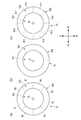
- (A) is a front view schematically showing the lighting unit for the first low beam.
- (B) is a front view schematically showing a high beam lighting unit.
- (C) is a front view schematically showing the lighting unit for the second low beam.
- (A) is a diagram schematically showing a light distribution pattern formed on a virtual screen when a low beam is emitted.
- (B) is a diagram schematically showing a light distribution pattern formed on a virtual screen when a high beam is emitted. It is a front view of a vehicle. It is the schematic which shows the vertical cross section of the lamp for a left-hand vehicle. It is a front view of a lamp unit. It is a rear view of a lamp unit. It is a cross-sectional view which shows the lamp unit cut along the line AA shown in FIG. FIG.
- FIG. 5 is an enlarged cross-sectional view showing a lens unit of a low beam lighting unit arranged at the left end of the lamp unit.
- A is a front view schematically showing a low beam lighting unit arranged at the right end of the lamp unit.
- (B) is a front view schematically showing a high beam lighting unit.
- C) is a front view schematically showing a low beam lighting unit arranged at the left end of the lamp unit.
- It is a front view of a vehicle. It is the schematic which shows the vertical cross section of the lamp for a left-hand vehicle.
- It is a perspective view of a lamp unit.
- It is a front view of a lamp unit.
- It is a cross-sectional view which shows the lamp unit cut along the line AA shown in FIG.
- FIG. 1 is a front view schematically showing a low beam lighting unit arranged at the right end.
- B is a front view schematically showing a high beam lighting unit.
- C is a front view schematically showing a low beam lighting unit arranged at the left end.
- horizontal direction In the description of the present embodiment, for convenience of explanation, "horizontal direction”, “vertical direction”, and “front-back direction” may be appropriately referred to. These directions are relative directions set for the lamp unit 3 shown in FIG.
- the "left-right direction” is a direction including the “left direction” and the “right direction”.
- the “vertical direction” is a direction including “upward direction” and “downward direction”.
- the "front-back direction” is a direction including the "forward direction” and the "rear direction”.
- One of the left-right direction, the up-down direction, and the front-back direction shall be orthogonal to the remaining two directions.
- the "horizontal direction” is a direction perpendicular to the vertical direction (vertical direction), and is a direction including a horizontal direction and a front-back direction.
- the directions set for the lighting unit 3 are the directions set for the vehicle 1 and the left-hand vehicle lighting tool 2L (horizontal direction, vertical direction, front-rear direction). It shall match the direction).
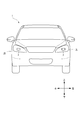
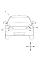
- FIG. 1 is a front view of a vehicle 1 provided with a left side vehicle light fixture 2L and a right side vehicle light fixture 2R.
- the left front vehicle lighting 2L is arranged on the left front side of the vehicle 1
- the right vehicle lighting 2R is arranged on the right front side of the vehicle 1.
- the same lamp unit 3 is mounted on each of the left vehicle lamp 2L and the right vehicle lamp 2R.
- FIG. 2A is a schematic view showing the front surface of the lamp unit 3.
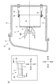
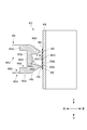
- FIG. 2B is a schematic view showing a vertical cross section of the left vehicle lamp 2L cut along the line AA shown in FIG. 2A.
- the left vehicle lamp 2L includes a lamp housing 12, a lamp cover 14 covering an opening of the lamp housing 12, and a lamp unit 3.
- the lamp unit 3 is arranged in the lamp chamber S formed by the lamp housing 12 and the lamp cover 14.
- FIG. 3 is a perspective view of the lamp unit 3.
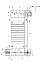
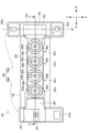
- FIG. 4 is a front view of the lamp unit 3.
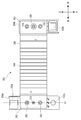
- FIG. 5 is a rear view of the lamp unit 3.
- the lamp unit 3 includes a heat sink 6, a bracket 9, an optical axis adjusting mechanism (specifically, aiming screws 92 and 93 and a fulcrum screw 95), a circuit board 8, and a circuit board 8.
- It includes light emitting elements 5a to 5d and an inner lens 4.
- the light emitting elements 5a to 5d may be collectively referred to as a light emitting element 5.
- the heat sink 6 (an example of a support member) is configured to release the heat released from the light emitting element 5 into the air in the lamp chamber S.
- the heat sink 6 is formed, for example, by extrusion molding an aluminum plate.
- the bracket 9 is made of a resin material such as polycarbonate or nylon, and has a first bracket portion 9a and a second bracket portion 9b.
- the first bracket portion 9a is fixed to the heat sink 6 on one end side of the heat sink 6.
- the first bracket portion 9a is fixed to the left end portion 62 of the heat sink 6 by a pair of screws 112.
- the first bracket portion 9a is connected to an aiming screw 92 that functions as a first optical axis adjusting mechanism and a fulcrum screw 95 that functions as a fulcrum mechanism.
- the aiming screw 92 and the fulcrum screw 95 are inserted into the screw insertion holes 130a and 132a formed in the first bracket portion 9a, respectively (see FIG. 3).
- the first bracket portion 9a is supported by the lamp housing 12 via the aiming screw 92 and the fulcrum screw 95.
- the aiming screw 92 is configured to adjust the position of the optical axis Ax (see FIG. 2B) of the lamp unit 3 in the vertical direction of the left vehicle lamp 2L (or the lamp unit 3).
- the aiming screw 92 is configured to rotate the lamp unit 3 about the first rotation axis A1 passing through the fulcrum screw 95 and the aiming screw 93.
- the first rotation axis A1 extends so as to be parallel to the left-right direction of the lamp unit 3. Since the lamp unit 3 is tilted about the first rotation axis A1 by moving the aiming screw 92 in the front-rear direction, the position of the optical axis Ax in the vertical direction can be adjusted. Since the first bracket portion 9a is fixed to the left end portion 62 of the heat sink 6 in this way, the aiming screw 92 adjusts the position of the optical axis Ax of the lamp unit 3 in the vertical direction via the first bracket portion 9a. can do.
- the second bracket portion 9b is arranged so as to face each other via the heat sink 6 in a state of being completely separated from the first bracket portion 9a.
- each of the first bracket portion 9a and the second bracket portion 9b is a completely independent component from each other.
- the second bracket portion 9b is arranged so as to be substantially parallel to the first bracket portion 9a.
- the second bracket portion 9b may be arranged so as to be completely parallel to the first bracket portion 9a, or may be arranged at a predetermined angle ⁇ with respect to the first bracket portion 9a (for example, 0 ° ⁇ ). It may be arranged so as to be tilted by ⁇ 30 °).
- the second bracket portion 9b is fixed to the heat sink 6 on the other end side of the heat sink 6.
- the second bracket portion 9b is fixed to the right end portion 63 of the heat sink 6 by a pair of screws 110.
- the second bracket portion 9b is connected to an aiming screw 93 that functions as a second optical axis adjusting mechanism. Specifically, the aiming screw 93 is inserted into the screw insertion hole 132b formed in the second bracket portion 9b (see FIG. 3).
- the second bracket portion 9b is supported by the lamp housing 12 via the aiming screw 93.
- the aiming screw 93 is configured to adjust the position of the optical axis Ax of the lamp unit 3 in the horizontal direction of the lamp 2L for the left vehicle (lamp unit 3).
- the aiming screw 93 is configured to rotate the lamp unit 3 about the second rotation axis A2 passing through the fulcrum screw 95 and the aiming screw 92.
- the second rotation axis A2 extends so as to be parallel in the vertical direction and is orthogonal to the first rotation axis A1. Since the lamp unit 3 is tilted about the second rotation axis A2 by moving the aiming screw 93 in the front-rear direction, the position of the optical axis Ax in the horizontal direction can be adjusted. Since the second bracket portion 9b is fixed to the right end portion 63 of the heat sink 6 in this way, the aiming screw 93 adjusts the position of the optical axis Ax of the lamp unit 3 in the horizontal direction via the second bracket portion 9b. can do.
- a first positioning pin 116 is provided on the first bracket portion 9a.
- the first positioning pin 116 is inserted into the first positioning hole 69 formed in the left end portion 62 of the heat sink 6.
- a first positioning recess 95a for accommodating the left end portion 62 of the heat sink 6 is formed in the first bracket portion 9a. With the left end portion 62 of the heat sink 6 housed in the first positioning recess 95a, the upper peripheral wall 97a of the first positioning recess 95a is in contact with the upper end surface 164 of the heat sink 6.
- the side peripheral wall 98a of the first positioning recess 95a is in contact with the left end surface 162 of the heat sink 6, and the lower peripheral wall 99a of the first positioning recess 95a is in contact with the lower end surface 165 of the heat sink 6.
- the first positioning pin 116 and the first positioning recess 95a function as a first positioning mechanism configured to determine the positional relationship between the first bracket portion 9a and the heat sink 6. After the positional relationship between the heat sink 6 and the first bracket portion 9a is determined by the first positioning pin 116 and the first positioning recess 95a, the first bracket portion 9a and the heat sink 6 are fixed to each other by a pair of screws 112. NS.
- the second positioning pin 118 is provided on the second bracket portion 9b.
- the second positioning pin 118 is inserted into the second positioning hole 68 formed in the right end portion 63 of the heat sink 6.
- a second positioning recess 95b for accommodating the right end portion 63 of the heat sink 6 is formed in the second bracket portion 9b. With the right end 63 of the heat sink 6 housed in the second positioning recess 95b, the upper peripheral wall 97b of the second positioning recess 95b is in contact with the upper end surface 164 of the heat sink 6.
- the side peripheral wall 98b of the second positioning recess 95b is in contact with the right end surface 163 of the heat sink 6, and the lower peripheral wall 99b of the second positioning recess 95b is in contact with the lower end surface 165 of the heat sink 6.
- the second positioning pin 118 and the second positioning recess 95b function as a second positioning mechanism configured to determine the positional relationship between the second bracket portion 9b and the heat sink 6. After the positional relationship between the heat sink 6 and the second bracket portion 9b is determined by the second positioning pin 118 and the second positioning recess 95b, the second bracket portion 9b and the heat sink 6 are fixed to each other by a pair of screws 110. NS.
- the first positioning pin 116 and the first positioning recess 95a position the first bracket portion 9a and the heat sink 6.
- the second positioning pin 118 and the second positioning recess 95b position the second bracket portion 9b and the heat sink 6.
- the first bracket portion 9a and the second bracket portion 9b can be arranged substantially parallel to each other.
- the bracket 9 and the heat sink 6 can be positioned so that the first rotation axis A1 is parallel to the left-right direction and the second rotation axis A2 is parallel to the vertical direction.
- the circuit board 8 is arranged on the front surface 60 of the heat sink 6.
- the circuit board 8 is electrically connected to a power supply circuit (not shown).
- the light emitting elements 5a to 5d are arranged on the circuit board 8 and are electrically connected to a light source drive circuit (not shown) via the circuit board 8.
- the light emitting element 5 is, for example, a semiconductor light emitting element such as an LED.
- the light emitting element 5 is configured to emit white light to the outside, and may include, for example, a blue LED and a yellow phosphor.
- the light emitting elements 5a to 5d are arranged on the same straight line in the left-right direction.
- the light emitting element 5b constituting the high beam lighting unit 7b and the light emitting element 5c constituting the high beam lighting unit 7c are the light emitting element 5a forming the first low beam lighting unit 7a and the second low beam lighting unit in the left-right direction. It is arranged between the light emitting element 5d and the light emitting element 5d constituting the 7d.
- Each of the light emitting elements 5a to 5c is arranged on the circuit board 8 so that the lower ends thereof are parallel to the left-right direction, while the lower ends of the light emitting elements 5d are oblique to the left-right direction. Is arranged on the circuit board 8. Since the lower end of the light emitting element 5d is oblique with respect to the left-right direction, the second low beam lighting unit 7d has a low beam light distribution pattern P2 (second low beam light distribution) having an oblique cut-off line L2, as will be described later. An example of a pattern) can be formed (see FIG. 9A).
- the inner lens 4 is arranged on the front surface 60 of the heat sink 6 so as to cover the light emitting elements 5a to 5d.
- the inner lens 4 is formed of, for example, a transparent resin material such as polycarbonate or acrylic resin.
- the inner lens 4 has lens units 40a to 40d arranged on the same straight line in the left-right direction. Each lens unit 40a to 40d is integrally formed.
- the lens unit 40a faces the light emitting element 5a in the front-rear direction.
- the lens unit 40a is configured to emit light emitted from the light emitting element 5a toward the outside of the vehicle 1 to form a low beam light distribution pattern P1 having a horizontal cut-off line L1 (FIG. 9 (FIG. 9).
- FIG. 9A is a diagram schematically showing a light distribution pattern formed on a virtual screen arranged 25 m ahead of the vehicle 1 when the low beam is emitted.
- FIG. 9B is a diagram schematically showing a light distribution pattern formed on the virtual screen when the high beam is emitted.
- the low beam light distribution pattern P1 is formed so as to extend along the HH line.
- the lens unit 40a has a central light transmitting portion 42a and a peripheral light transmitting portion 43a.
- the central light transmitting portion 42a is configured to face the light emitting element 5a in the front-rear direction and to emit a part of the light emitted from the light emitting element 5a toward the outside of the vehicle 1.
- the peripheral light transmitting portion 43a is provided so as to surround the central light transmitting portion 42a, and is configured to totally reflect the other part of the light emitted from the light emitting element 5a toward the outside of the vehicle 1.
- the low beam light distribution pattern P1 is formed by synthesizing the light distribution pattern formed by the central light transmitting portion 42a and the light distribution pattern formed by the peripheral light transmitting portion 43a.
- the recess 54a communicates with the recess 56a, and the diameter of the recess 56a is larger than the diameter of the recess 54a.
- the central light transmitting portion 42a has an emitting surface 52a forming the bottom surface of the recess 54a and an incident surface 47a.
- the peripheral light transmitting portion 43a has an exit surface 53a forming the bottom surface of the recess 56a, an incident surface 49a, and a total reflection surface 46a.
- the light emitting element 5a and the lens unit 40a constitute a first low beam illumination unit 7a configured to form a low beam light distribution pattern P1.
- the lens unit 40b faces the light emitting element 5b in the front-rear direction.
- the lens unit 40b is configured to form a high beam light distribution pattern P3 by emitting light emitted from the light emitting element 5b toward the outside of the vehicle 1 (see FIG. 9B).
- the lens unit 40b has a central light transmitting portion 42b and a peripheral light transmitting portion 43b.
- the central light transmitting portion 42b is configured to face the light emitting element 5b in the front-rear direction and to emit a part of the light emitted from the light emitting element 5b toward the outside of the vehicle 1.
- the peripheral light transmitting portion 43b is provided so as to surround the central light transmitting portion 42b, and is configured to totally reflect the other part of the light emitted from the light emitting element 5b toward the outside of the vehicle 1.
- the high beam light distribution pattern P3 is formed by synthesizing the light distribution pattern formed by the central light transmitting portion 42b and the light distribution pattern formed by the peripheral light transmitting portion 43b.
- the recess 54b communicates with the recess 56b, and the diameter of the recess 56b is larger than the diameter of the recess 54b.
- the central light transmitting portion 42b has an emitting surface 52b forming the bottom surface of the recess 54b and an incident surface 47b.
- the peripheral light transmitting portion 43b has an exit surface 53b forming the bottom surface of the recess 56b, an incident surface 49b, and a total reflection surface 46b.
- the light emitting element 5b and the lens unit 40b constitute a high beam illumination unit 7b configured to form a high beam light distribution pattern P3.
- the lens unit 40c faces the light emitting element 5c in the front-rear direction.
- the lens unit 40c has the same configuration as the lens unit 40b, and is configured to form a high beam light distribution pattern P4 by emitting light emitted from the light emitting element 5c toward the outside of the vehicle 1. (See Fig. 9 (b)).
- the high beam light distribution pattern P4 formed by the lens unit 40c completely overlaps the high beam light distribution pattern P3 formed by the lens unit 40b.
- the lens unit 40c has a central light transmitting portion 42c and a peripheral light transmitting portion 43c.
- the central light transmitting portion 42c is configured to face the light emitting element 5c in the front-rear direction and to emit a part of the light emitted from the light emitting element 5c toward the outside of the vehicle 1.
- the peripheral light transmitting portion 43c is provided so as to surround the central light transmitting portion 42c, and is configured to totally reflect the other part of the light emitted from the light emitting element 5c toward the outside of the vehicle 1.
- the high beam light distribution pattern P4 is formed by synthesizing the light distribution pattern formed by the central light transmitting portion 42c and the light distribution pattern formed by the peripheral light transmitting portion 43c.
- the recess 54c communicates with the recess 56c, and the diameter of the recess 56c is larger than the diameter of the recess 54c.
- the central light transmitting portion 42c has an emitting surface 52c forming the bottom surface of the recess 54c and an incident surface 47c.
- the peripheral light transmitting portion 43c has an exit surface 53c forming the bottom surface of the recess 56c, an incident surface 49c, and a total reflection surface 46c.
- the light emitting element 5c and the lens unit 40c constitute a high beam illumination unit 7c configured to form a high beam light distribution pattern P4.
- the lens unit 40d faces the light emitting element 5d in the front-rear direction.
- the lens unit 40d is configured to emit light emitted from the light emitting element 5d toward the outside of the vehicle 1 to form a low beam light distribution pattern P2 having an oblique cut-off line L2 (FIG. 9 (FIG. 9). a) See).
- the low beam light distribution pattern P2 is formed so as to extend obliquely with respect to the HH line.
- the low beam light distribution pattern P1 formed by the lens unit 40a and the low beam light distribution pattern P2 formed by the lens unit 40d form a light distribution pattern when the low beam is emitted.
- the lens unit 40d has a central light transmitting portion 42d and a peripheral light transmitting portion 43d.
- the central light transmitting portion 42d is configured to face the light emitting element 5d in the front-rear direction and to emit a part of the light emitted from the light emitting element 5d toward the outside of the vehicle 1.
- the peripheral light transmitting portion 43d is provided so as to surround the central light transmitting portion 42d, and is configured to totally reflect the other part of the light emitted from the light emitting element 5d toward the outside of the vehicle 1.
- the low beam light distribution pattern P2 is formed by synthesizing the light distribution pattern formed by the central light transmitting portion 42d and the light distribution pattern formed by the peripheral light transmitting portion 43d.
- the recess 54d communicates with the recess 56d, and the diameter of the recess 56d is larger than the diameter of the recess 54d.
- the central light transmitting portion 42d has an emitting surface 52d forming the bottom surface of the recess 54d and an incident surface 47d.
- the peripheral light transmitting portion 43d has an exit surface 53d forming the bottom surface of the recess 56d, an incident surface 49d, and a total reflection surface 46d.
- the light emitting element 5d and the lens unit 40d constitute a second low beam illumination unit 7d configured to form the low beam light distribution pattern P2.
- the lighting fixture unit 3 includes the first low beam lighting unit 7a (hereinafter, simply referred to as “lighting unit 7a”) and the high beam lighting units 7b, 7c (hereinafter, simply “lighting”). Units 7b and 7c ”) and a second low beam lighting unit 7d (hereinafter, simply referred to as“ lighting unit 7d ”). As shown in FIG. 6, these lighting units 7a to 7d are arranged side by side in the left-right direction. The lighting units 7b and 7c are arranged between the lighting unit 7a and the lighting unit 7d in the left-right direction.
- the exit surfaces 52a to 52d of the central light transmitting portions 42a to 42d are located on the same plane, and the exit surfaces 53a to 53d of the peripheral light transmitting portions 43a to 43d are located on the same plane.
- the distance D1 between the light emitting element 5a and the light emitting element 5b in the left-right direction satisfies 0 mm ⁇ D1 ⁇ 75 mm
- the distance D2 between the light emitting element 5c and the light emitting element 5d in the left-right direction is 0 mm ⁇ D2 ⁇ 75 mm.
- the lighting unit 3 emits a low beam
- the lighting of the lighting unit 7a makes it difficult for the lighting unit 7b to be turned off from the outside of the vehicle 1, and the lighting of the lighting unit 7d turns off the lighting unit 7c. Is difficult to see from the outside of the vehicle 1.
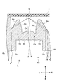
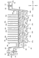
- FIG. 7 is an enlarged cross-sectional view of the lens unit 40a.
- a part of the light emitted from the light emitting element 5a reaches the exit surface 52a after being incident on the incident surface 47a of the central light transmitting portion 42a.
- the light that has reached the exit surface 52a is emitted to the outside in a state of being diffused by the diffusion lens element 48a formed on the emission surface 52a.
- the other part of the light emitted from the light emitting element 5a is totally reflected by the total reflection surface 46a after being incident on the incident surface 49a of the peripheral light transmitting portion 43a.
- the light totally reflected by the total reflection surface 46a reaches the exit surface 53a and is then emitted to the outside in a state of being diffused by the diffusion lens element 48a formed on the emission surface 53a.
- the low beam light distribution pattern P1 is formed by the lens unit 40a.
- the lens units 40b to 40d also have the same configuration as the lens unit 40a.
- the exit surfaces of the lens units 40b to 40d also have diffusion lens elements 48b to 48d.
- each of the diffusion lens elements 48a to 48c formed in the lens units 40a to 40c is formed so as to extend substantially parallel in the vertical direction.
- FIG. 8A is a front view schematically showing the lighting unit 7a.
- FIG. 8B is a front view schematically showing the lighting unit 7b.
- FIG. 8C is a front view schematically showing the lighting unit 7d.
- the peripheral light transmitting portion 43a of the lens unit 40a is provided so as to surround the central light transmitting portion 42a in the circumferential direction thereof.
- the peripheral light transmitting portion 43a is divided into eight reflection regions R1 to R8 along the circumferential direction thereof.
- Each of the reflection regions R1 to R8 has an angle region of 45 ° from the center of the lens unit 40a.
- Each of the reflection regions R1 to R8 has a total reflection surface 46a having different outer shapes from each other.
- the peripheral light transmitting portion 43b of the lens unit 40b is provided so as to surround the central light transmitting portion 42b in the circumferential direction thereof.
- the peripheral light transmitting portion 43b is not divided into a plurality of reflection regions in the circumferential direction thereof. Since the lens unit 40c has the same configuration as the lens unit 40b, the peripheral light transmitting portion 43c of the lens unit 40c is not divided into a plurality of reflection regions in the circumferential direction thereof.
- the peripheral light transmitting portion 43d of the lens unit 40d is provided so as to surround the central light transmitting portion 42d in the circumferential direction thereof.
- the peripheral light transmitting portion 43d is divided into eight reflection regions R10 to R17 along the circumferential direction thereof.
- Each of the reflection regions R10 to R17 has an angle region of 45 ° from the center of the lens unit 40d.
- Each of the reflection regions R10 to R17 has a total reflection surface 46d having a different shape from each other.
- the bracket 9 since the first bracket portion 9a and the second bracket portion 9b are completely separated from each other, it is not necessary to manufacture different new brackets for each of a plurality of lamp units having different dimensions in the left-right direction. ..
- the bracket 9 can be applied to each of the plurality of lamp units 3 having different dimensions in the left-right direction. It will be possible.
- the other of the first bracket portion 9a and the second bracket portion 9b can be utilized for the lamp unit 3 which is not compatible with either one of the first bracket portion 9a and the second bracket portion 9b. Therefore, it is possible to reduce the mold cost for manufacturing the bracket 9. In this way, it is possible to reduce the manufacturing cost of the lamp unit 3 provided with the bracket 9.
- the aiming screw 92 can adjust the position of the optical axis Ax of the lamp unit 3 in the vertical direction via the first bracket portion 9a fixed to the heat sink 6.
- the aiming screw 93 can adjust the position of the optical axis Ax of the lamp unit 3 in the horizontal direction via the second bracket portion 9b fixed to the heat sink 6. Further, the heat radiated from the light emitting element 5 of the lamp unit 3 can be efficiently radiated to the outside of the left vehicle lamp 2L via the heat sink 6, the bracket 9, and the optical axis adjusting mechanism.
- the lamp unit 3 includes two high beam lighting units, but the number of high beam lighting units is not particularly limited.
- the number of high beam lighting units provided in the lamp unit 3 may be one.
- horizontal direction In the description of the present embodiment, for convenience of explanation, "horizontal direction”, “vertical direction”, and “front-back direction” may be appropriately referred to. These directions are relative directions set for the lamp unit 203 shown in FIG. 10 or 11.
- the "left-right direction” is a direction including the “left direction” and the “right direction”.
- the "vertical direction” is a direction including “upward direction” and “downward direction”.
- the "front-back direction” is a direction including the "forward direction” and the "rear direction”.
- One of the left-right direction, the up-down direction, and the front-back direction shall be orthogonal to the remaining two directions.
- the "horizontal direction” is a direction perpendicular to the vertical direction (vertical direction), and is a direction including a horizontal direction and a front-back direction.
- the directions set for the lighting unit 203 are the directions (horizontal direction, vertical direction, front-rear direction) set for the vehicle 1A and the left vehicle lighting tool 202L. It shall match the direction).
- FIG. 10 is a front view of the vehicle 1A provided with the left side vehicle lighting fixture 202L and the right side vehicle lighting fixture 202R.
- the left front vehicle lighting 202L is arranged on the left front side of the vehicle 1A
- the right vehicle lighting 202R is arranged on the right front side of the vehicle 1A.
- the same lamp unit 203 is mounted on each of the left vehicle lamp 202L and the right vehicle lamp 202R.
- FIG. 11 shows a vertical cross-sectional view of the left vehicle lamp 202L.
- the left vehicle lamp 202L includes a lamp housing 212, a lamp cover 214 covering the opening of the lamp housing 212, and a lamp unit 203.
- the lamp unit 203 is arranged in the lamp chamber S2 formed by the lamp housing 212 and the lamp cover 214.
- FIG. 12 is a front view of the lamp unit 203.
- FIG. 13 is a rear view of the lamp unit 203.
- FIG. 14 is a cross-sectional view of the lamp unit 203 cut along the line AA shown in FIG.
- the lamp unit 203 includes a heat sink 206, a bracket 209, a circuit board 208, light emitting elements 205a to 205d, an inner lens 204, and a position adjusting mechanism (specifically, movable).
- a portion 293, a first fixing portion 292, and a second fixing portion 295) are provided.
- the light emitting elements 205a to 205d may be collectively referred to as a light emitting element 205.
- the heat sink 206 is configured to release the heat released from the light emitting element 205 into the air in the lamp chamber S2.
- the heat sink 206 is formed, for example, by extrusion molding an aluminum plate.
- the heat sink 206 has a plurality of fins 264 arranged at equal intervals in the left-right direction so as to be separated from each other.
- the bracket 209 is formed of, for example, a resin material such as polycarbonate or nylon, and has a first bracket portion 209a and a second bracket portion 209b that are completely separated from each other.
- the first bracket portion 209a is fixed to the left end portion 262 of the heat sink 206 by a screw 312, and also has a first aiming screw (not shown) and a function as an optical axis adjusting mechanism. It is connected to a fulcrum screw (not shown) that functions as a fulcrum mechanism. Specifically, the first aiming screw and the fulcrum screw are inserted into the screw insertion holes 330a and 332a formed in the first bracket portion 209a, respectively. The first aiming screw is configured to adjust the optical axis Ax (see FIG. 11) of the lamp unit 203 in the vertical direction.
- the second bracket portion 209b is fixed to the right end portion 263 of the heat sink 206 via a pair of screws 310, and is connected to a second aiming screw (not shown) that functions as an optical axis adjusting mechanism. Specifically, the second aiming screw is inserted into the screw insertion hole 332b formed in the second bracket portion 209b. The second aiming screw is configured to adjust the optical axis Ax of the lamp unit 203 in the horizontal direction.
- the circuit board 208 is arranged on the front surface 260 of the heat sink 206.
- the circuit board 208 is electrically connected to a power supply circuit (not shown).
- the light emitting elements 205a to 205d are arranged on the circuit board 208 and are electrically connected to a light source drive circuit (not shown) via the circuit board 208.
- the light emitting element 205 is, for example, a semiconductor light emitting element such as an LED.
- the light emitting element 205 is configured to emit white light to the outside, and may include, for example, a blue LED and a yellow phosphor.
- the light emitting elements 205a to 205d are arranged on the same straight line in the left-right direction.
- the light emitting element 205b constituting the high beam lighting unit 207b and the light emitting element 205c constituting the high beam lighting unit 207c constitute the light emitting element 205a constituting the low beam lighting unit 207a and the low beam lighting unit 207d in the left-right direction. It is arranged between the light emitting element 205d and the light emitting element 205d.
- Each of the light emitting elements 205b to 205d is arranged on the circuit board 208 so that the lower ends thereof are parallel to the left-right direction, while the lower ends of the light emitting elements 205a are oblique to the left-right direction. Is arranged on the circuit board 208. Since the lower end of the light emitting element 205a is oblique with respect to the left-right direction, the low-beam lighting unit 207a can form a low-beam light distribution pattern P2 having an oblique cut-off line L2 as described later (FIG. 9). See (a)).
- the inner lens 204 is arranged in front of the heat sink 206 so as to cover the light emitting elements 205a to 205d.
- the left end portion 342 of the inner lens 204 is connected to the first bracket portion 209a and the heat sink 206 via the first fixing portion 292 and the second fixing portion 295.
- the right end portion 343 of the inner lens 204 is connected to the second bracket portion 209b and the heat sink 206 via the movable portion 293.
- the inner lens 204 is made of a transparent resin material such as polycarbonate or acrylic resin.
- the inner lens 204 has lens units 240a to 240d arranged on the same straight line in the left-right direction.
- the lens units 240a to 240d are integrally formed.
- the lens unit 240a faces the light emitting element 205a (an example of the second light emitting element) in the front-rear direction.
- the lens unit 240a forms a low beam light distribution pattern P2 (an example of a second low beam light distribution pattern) having an oblique cut-off line L2 by emitting light emitted from the light emitting element 205a toward the outside of the vehicle 1A.
- FIG. 9A is a diagram schematically showing a light distribution pattern formed on a virtual screen arranged 25 m ahead of the vehicle 1A when the low beam is emitted.
- FIG. 9A is a diagram schematically showing a light distribution pattern formed on a virtual screen arranged 25 m ahead of the vehicle 1A when the low beam is emitted.
- FIG. 9B is a diagram schematically showing a light distribution pattern formed on the virtual screen when the high beam is emitted.
- the low beam light distribution pattern P2 is formed so as to extend obliquely with respect to the HH line.
- the lens unit 240a has a central light transmitting portion 242a and a peripheral light transmitting portion 243a.
- the central light transmitting portion 242a is configured to face the light emitting element 205a in the front-rear direction and to emit a part of the light emitted from the light emitting element 205a toward the outside of the vehicle 1A.
- the peripheral light transmitting portion 243a is provided so as to surround the central light transmitting portion 242a, and is configured to totally reflect the other part of the light emitted from the light emitting element 205a toward the outside of the vehicle 1A.
- the low beam light distribution pattern P2 is formed by synthesizing the light distribution pattern formed by the central light transmitting portion 242a and the light distribution pattern formed by the peripheral light transmitting portion 243a.
- the recess 254a communicates with the recess 256a, and the diameter of the recess 256a is larger than the diameter of the recess 254a.
- the central light transmitting portion 242a has an exit surface 252a forming the bottom surface of the recess 254a and an incident surface 247a.
- the peripheral light transmitting portion 243a has an exit surface 253a forming the bottom surface of the recess 256a, an incident surface 249a, and a total reflection surface 246a.
- the light emitting element 205a and the lens unit 240a constitute a low beam illumination unit 207a configured to form a low beam light distribution pattern P2.
- the lens unit 240b (an example of a third lens unit) faces the light emitting element 205b (an example of a third light emitting element) in the front-rear direction.
- the lens unit 240b is configured to form a high beam light distribution pattern P3 by emitting light emitted from the light emitting element 205b toward the outside of the vehicle 1A (see FIG. 9B).
- the lens unit 240b has a central light transmitting portion 242b and a peripheral light transmitting portion 243b.
- the central light transmitting portion 242b is configured to face the light emitting element 205b in the front-rear direction and to emit a part of the light emitted from the light emitting element 205b toward the outside of the vehicle 1A.
- the peripheral light transmitting portion 243b is provided so as to surround the central light transmitting portion 242b, and is configured to totally reflect the other part of the light emitted from the light emitting element 205b toward the outside of the vehicle 1A.
- the high beam light distribution pattern P3 is formed by synthesizing the light distribution pattern formed by the central light transmitting portion 242b and the light distribution pattern formed by the peripheral light transmitting portion 243b.
- the recess 254b communicates with the recess 256b, and the diameter of the recess 256b is larger than the diameter of the recess 254b.
- the central light transmitting portion 242b has an exit surface 252b forming the bottom surface of the recess 254b and an incident surface 247b.
- the peripheral light transmitting portion 243b has an exit surface 253b forming the bottom surface of the recess 256b, an incident surface 249b, and a total reflection surface 246b.
- the light emitting element 205b and the lens unit 240b constitute a high beam illumination unit 207b configured to form a high beam light distribution pattern P3.
- the lens unit 240c faces the light emitting element 205c in the front-rear direction.
- the lens unit 240c has the same configuration as the lens unit 240b, and is configured to form a high beam light distribution pattern P4 by emitting light emitted from the light emitting element 205c toward the outside of the vehicle 1A. (See Fig. 9 (b)).
- the high beam light distribution pattern P4 formed by the lens unit 240c completely overlaps the high beam light distribution pattern P3 formed by the lens unit 240b.
- the lens unit 240c has a central light transmitting portion 242c and a peripheral light transmitting portion 243c.
- the central light transmitting portion 242c is configured to face the light emitting element 205c in the front-rear direction and to emit a part of the light emitted from the light emitting element 205c toward the outside of the vehicle 1A.
- the peripheral light transmitting portion 243c is provided so as to surround the central light transmitting portion 242c, and is configured to totally reflect the other part of the light emitted from the light emitting element 205c toward the outside of the vehicle 1A.
- the high beam light distribution pattern P4 is formed by synthesizing the light distribution pattern formed by the central light transmitting portion 242c and the light distribution pattern formed by the peripheral light transmitting portion 243c.
- the recess 254c communicates with the recess 256c, and the diameter of the recess 256c is larger than the diameter of the recess 254c.
- the central light transmitting portion 242c has an exit surface 252c forming the bottom surface of the recess 254c and an incident surface 247c.
- the peripheral light transmitting portion 243c has an exit surface 253c forming the bottom surface of the recess 256c, an incident surface 249c, and a total reflection surface 246c.
- the light emitting element 205c and the lens unit 240c constitute a high beam illumination unit 207c configured to form a high beam light distribution pattern P4.
- the lens unit 240d (an example of the first lens unit) faces the light emitting element 205d (an example of the first light emitting element) in the front-rear direction.
- the lens unit 240d forms a low beam light distribution pattern P1 (an example of a first low beam light distribution pattern) having a horizontal cut-off line L1 by emitting light emitted from the light emitting element 205d toward the outside of the vehicle 1A. (See FIG. 9A).
- the low beam light distribution pattern P1 is formed so as to extend along the HH line.
- the low beam light distribution pattern P1 formed by the lens unit 240d and the low beam light distribution pattern P2 formed by the lens unit 240a form a light distribution pattern when the low beam is emitted.
- the lens unit 240d has a central light transmitting portion 242d and a peripheral light transmitting portion 243d.
- the central light transmitting portion 242d is configured to face the light emitting element 205d in the front-rear direction and to emit a part of the light emitted from the light emitting element 205d toward the outside of the vehicle 1A.
- the peripheral light transmitting portion 243d is provided so as to surround the central light transmitting portion 242d, and is configured to totally reflect the other part of the light emitted from the light emitting element 205d toward the outside of the vehicle 1A.
- the low beam light distribution pattern P1 is formed by synthesizing the light distribution pattern formed by the central light transmitting portion 242d and the light distribution pattern formed by the peripheral light transmitting portion 243d.
- the lens unit 240d is formed with two recesses 254d and 256d.
- the recess 254d communicates with the recess 256d, and the diameter of the recess 256d is larger than the diameter of the recess 254d.
- the central light transmitting portion 242d has an exit surface 252d forming the bottom surface of the recess 254d and an incident surface 247d.
- the peripheral light transmitting portion 243d has an exit surface 253d forming the bottom surface of the recess 256d, an incident surface 249d, and a total reflection surface 246d.
- the light emitting element 205d and the lens unit 240d constitute a low beam illumination unit 207d configured to form a low beam light distribution pattern P1.
- the lamp unit 203 includes the low beam lighting unit 207a (hereinafter, simply referred to as “lighting unit 207a”) and the high beam lighting units 207b, 207c (hereinafter, simply “lighting unit 207b”). , 207c ”) and a low beam lighting unit 207d (hereinafter, simply referred to as” lighting unit 207d "). As shown in FIG. 14, these lighting units 207a to 207d are arranged side by side in the left-right direction. The lighting units 207b and 207c are arranged between the lighting unit 207a and the lighting unit 207d in the left-right direction.
- the exit surfaces 252a to 252d of the central light transmitting portions 242a to 242d are located on the same plane, and the exit surfaces 253a to 253d of the peripheral light transmitting portions 243a to 243d are located on the same plane.
- the distance D1 between the light emitting element 205a and the light emitting element 205b in the left-right direction satisfies 0 mm ⁇ D1 ⁇ 75 mm, and the distance D2 between the light emitting element 205c and the light emitting element 205d in the left-right direction is 0 mm ⁇ D2 ⁇ 75 mm.
- the lighting unit 203 emits a low beam
- the lighting of the lighting unit 207a makes it difficult for the lighting unit 207b to be turned off from the outside of the vehicle 1A, and the lighting of the lighting unit 207d turns off the lighting unit 207c. Is difficult to see from the outside of the vehicle 1A.
- FIG. 15 is an enlarged cross-sectional view of the lens unit 240d.
- a part of the light emitted from the light emitting element 205d reaches the exit surface 252d after being incident on the incident surface 247d of the central light transmitting portion 242d.
- the light that has reached the exit surface 252d is emitted to the outside in a state of being diffused by the diffusion lens element 248d formed on the emission surface 252d.
- the other part of the light emitted from the light emitting element 205d is totally reflected by the total reflection surface 246d after being incident on the incident surface 249d of the peripheral light transmitting portion 243d.
- the light totally reflected by the total reflection surface 246d reaches the exit surface 253d and is then emitted to the outside in a state of being diffused by the diffusion lens element 248d formed on the emission surface 253d.
- the low beam light distribution pattern P1 is formed by the lens unit 240d.
- the lens units 240a to 240c also have the same configuration as the lens unit 240d.
- the exit surfaces of the lens units 240a to 240c also have diffusion lens elements 248a to 248c.
- each of the diffusion lens elements 248b to 248d formed in the lens units 240b to 240d is formed so as to extend substantially parallel in the vertical direction.
- FIG. 16A is a front view schematically showing the lighting unit 207a.
- FIG. 16B is a front view schematically showing the lighting unit 207b.
- FIG. 16C is a front view schematically showing the lighting unit 207d.
- the peripheral light transmitting portion 243a of the lens unit 240a is provided so as to surround the central light transmitting portion 242a in the circumferential direction thereof.
- the peripheral light transmitting portion 243a is divided into eight reflection regions R31 to R38 along the circumferential direction thereof.
- Each of the reflection regions R31 to R38 has an angle region of 45 ° from the center of the lens unit 240a.
- Each of the reflection regions R31 to R38 has a total reflection surface 246a having different outer shapes from each other.
- the peripheral light transmitting portion 243b of the lens unit 240b is provided so as to surround the central light transmitting portion 242b in the circumferential direction thereof.
- the peripheral light transmitting portion 243b is not divided into a plurality of reflection regions in the circumferential direction thereof. Since the lens unit 240c has the same configuration as the lens unit 240b, the peripheral light transmitting portion 243c of the lens unit 240c is not divided into a plurality of reflection regions in the circumferential direction thereof.
- the peripheral light transmitting portion 243d of the lens unit 240d is provided so as to surround the central light transmitting portion 242d in the circumferential direction thereof.
- the peripheral light transmitting portion 243d is divided into eight reflection regions R40 to R47 along the circumferential direction thereof.
- Each of the reflection regions R40 to R47 has an angle region of 45 ° from the center of the lens unit 240d.
- Each of the reflection regions R40 to R47 has a total reflection surface 246d having a different shape from each other.
- the first fixed portion 292, the second fixed portion 295, and the movable portion 293 function as a position adjusting mechanism configured to adjust the relative positional relationship of the inner lens 204 with respect to the heat sink 206.
- the first fixed portion 292, the second fixed portion 295, and the movable portion 293 are arranged between the inner lens 204 and the heat sink 206 in the front-rear direction of the lamp unit 203.
- Each of the first fixed portion 292, the second fixed portion 295, and the movable portion 293 is configured as, for example, a screw.
- the first fixing portion 292 is connected to the heat sink 206, the first bracket portion 209a, and the inner lens 204 at the left end portion 342 of the inner lens 204, respectively.
- the second fixing portion 295 faces the first fixing portion 292 in the vertical direction of the lamp unit 203, and at the left end portion 342 of the inner lens 204, the heat sink 206, the first bracket portion 209a, and the inner lens 204 Each is connected.
- the movable portion 293 is connected to the heat sink 206, the second bracket portion 209b, and the inner lens 204 at the right end portion 343 of the inner lens 204, respectively.
- the movable portion 293 is inserted into the insertion hole 363 of the heat sink 206, the insertion hole 290b of the second bracket portion 209b, and the insertion hole 340 of the inner lens 204.
- the right end portion 343 of the inner lens 204 engaged with the movable portion 293 moves in the front-rear direction.
- the inner lens 204 rotates in the horizontal direction about the rotation axis A1 (see FIG. 12) passing through the first fixed portion 292 and the second fixed portion 295.
- the inner lens 204 rotates and moves in the horizontal direction around the rotation axis A1 through the rotational movement of the movable portion 293, the relative position of the inner lens 204 with respect to the heat sink 206 changes.
- the circuit board 208 is fixed to the heat sink 206 via a fixing means such as a screw, the positions of the light emitting elements 205a to 205d mounted on the circuit board 208 are fixed to the heat sink 206. Therefore, as the inner lens 204 rotates and moves, the relative positional relationship between the lens units 240a to 240d and the light emitting elements 205a to 205d is adjusted.
- the relative positional relationship between the lens unit 240a and the light emitting element 205a can be adjusted, so that the desired low beam light distribution can be adjusted.
- the pattern P1 can be obtained.
- a desired high beam light distribution pattern P3 can be obtained.
- a desired high beam light distribution pattern P4 can be obtained.
- a desired low beam light distribution pattern P2 can be obtained.
- the relative positional relationship between the lens units 240a to 240d and the light emitting elements 205a to 205d can be obtained. It can be adjusted and a desired light distribution pattern can be obtained. In this respect, even when the positioning accuracy between the light emitting elements 205a to 205d and the lens units 240a to 240d is low or the processing accuracy of the lens units 240a to 240d is low, the lens unit 240a using the position adjusting mechanism is used. A desired light distribution pattern can be obtained through position adjustment between the 240d and the light emitting elements 205a to 205d.
- the lens units 240a to 240d are arranged between the movable portion 293 and the rotation axis A1 in the left-right direction. Further, among the lens units 240a to 240d, the lens unit 240a is arranged at the position farthest from the rotation axis A1. Therefore, the amount of change in the relative position between the lens unit 240a and the light emitting element 205a can be maximized as the inner lens 204 rotates about the rotation axis A1. By adjusting the relative positional relationship of the inner lens 204 with respect to the heat sink 206 using the position adjusting mechanism in this way, a desired low beam light distribution pattern P2 can be obtained.
- the lamp unit 203 includes two high beam lighting units, but the number of high beam lighting units is not particularly limited.
- the number of high beam lighting units provided in the lamp unit 203 may be one.
- horizontal direction In the description of the present embodiment, for convenience of explanation, "horizontal direction”, “vertical direction”, and “front-back direction” may be appropriately referred to. These directions are relative directions set for the lamp unit 403 shown in FIG.
- the "left-right direction” is a direction including the “left direction” and the “right direction”.
- the "vertical direction” is a direction including “upward direction” and “downward direction”.
- the "front-back direction” is a direction including the "forward direction” and the "rear direction”.
- One of the left-right direction, the up-down direction, and the front-back direction shall be orthogonal to the remaining two directions.
- the "horizontal direction” is a direction perpendicular to the vertical direction (vertical direction), and is a direction including a horizontal direction and a front-back direction.
- the directions set for the lighting unit 403 are the directions set for the vehicle 1B and the left vehicle lighting tool 402L (horizontal direction, vertical direction, front-rear direction). It shall match the direction).
- FIG. 17 is a front view of the vehicle 1B provided with the left vehicle lighting fixture 402L and the right vehicle lighting fixture 402R.
- the left vehicle lighting fixture 402L is arranged on the left front side of the vehicle 1B
- the right vehicle lighting fixture 402R is arranged on the right front side of the vehicle 1B.
- the same lamp unit 403 is mounted on each of the left vehicle lamp 402L and the right vehicle lamp 402R.
- FIG. 18 shows a vertical cross-sectional view of the left vehicle lamp 402L.
- the left vehicle lamp 402L includes a lamp housing 412, a lamp cover 414 that covers the opening of the lamp housing 412, and a lamp unit 403.
- the lamp unit 403 is arranged in the lamp chamber S3 formed by the lamp housing 412 and the lamp cover 414.
- FIG. 19 is a perspective view of the lamp unit 403.
- FIG. 20 is a front view of the lamp unit 403.
- FIG. 21 is a cross-sectional view showing a lamp unit 403 cut along the line AA shown in FIG. 20.
- the lamp unit 403 includes a heat sink 406, a bracket 409, a circuit board 408, light emitting elements 405a to 405d, and an inner lens 404.
- the light emitting elements 405a to 405d may be collectively referred to as a light emitting element 405.
- the heat sink 406 is configured to release the heat released from the light emitting element 405 into the air in the lamp chamber S3.
- the heat sink 406 is formed, for example, by extrusion molding an aluminum plate.
- the bracket 409 is formed of, for example, a resin material such as polycarbonate or nylon, and has a first bracket portion 409a and a second bracket portion 409b that are completely separated from each other.
- the first bracket portion 409a is fixed to the heat sink 406 at one end side of the heat sink 406, and is connected to an aiming screw 492 that functions as an optical axis adjusting mechanism and a fulcrum screw 495 that functions as a fulcrum mechanism (see FIG. 20). ).
- the aiming screw 492 is configured to adjust the optical axis Ax2 of the lamp unit 403 in the vertical direction.
- the second bracket portion 409b is fixed to the heat sink 406 on the other end side of the heat sink 406 and is connected to an aiming screw 493 (see FIG. 20) that functions as an optical axis adjusting mechanism.
- the aiming screw 493 is configured to adjust the optical axis Ax2 of the lamp unit 403 in the horizontal direction.
- the circuit board 408 is arranged on the front surface 460 of the heat sink 406.
- the circuit board 408 is electrically connected to a power supply circuit (not shown).
- the light emitting elements 405a to 405d are arranged on the circuit board 408 and are electrically connected to a light source drive circuit (not shown) via the circuit board 408.
- the light emitting element 405 is, for example, a semiconductor light emitting element such as an LED.
- the light emitting element 405 is configured to emit white light to the outside, and may include, for example, a blue LED and a yellow phosphor.
- the light emitting elements 405a to 405d are arranged on the same straight line in the left-right direction.
- the light emitting element 405b constituting the high beam lighting unit 407b and the light emitting element 405c constituting the high beam lighting unit 407c constitute the light emitting element 405a constituting the low beam lighting unit 407a and the low beam lighting unit 407d in the left-right direction. It is arranged between the light emitting element 405d and the light emitting element 405d.
- Each of the light emitting elements 405a to 405c is arranged on the circuit board 408 so that the lower ends thereof are parallel to the left-right direction, while the lower ends of the light emitting elements 405d are oblique to the left-right direction. Is arranged on the circuit board 408. Since the lower end of the light emitting element 405d is oblique with respect to the left-right direction, the low-beam lighting unit 407d can form a low-beam light distribution pattern P2 having an oblique cut-off line L2 as described later (FIG. 25). See (a)).
- the inner lens 404 is arranged on the front surface 460 of the heat sink 406 so as to cover the light emitting elements 405a to 405d.
- the inner lens 404 is made of a transparent resin material such as polycarbonate or acrylic resin.
- the inner lens 404 has lens units 440a to 440d arranged on the same straight line in the left-right direction. Each lens unit 440a to 440d is integrally formed.
- the lens unit 440a faces the light emitting element 405a (an example of the second light emitting element) in the front-rear direction.
- the lens unit 440a is configured to form a low beam light distribution pattern P1 having a horizontal cut-off line L1 by emitting light emitted from the light emitting element 405a toward the outside of the vehicle 1B (FIG. 25 (FIG. 25). a) See).
- FIG. 25A is a diagram schematically showing a light distribution pattern formed on a virtual screen arranged 25 m ahead of the vehicle 1B when the low beam is emitted.
- FIG. 25B is a diagram schematically showing a light distribution pattern formed on the virtual screen when the high beam is emitted.
- the low beam light distribution pattern P1 is formed so as to extend along the HH line.
- the lens unit 440a has a central light transmitting portion 442a and a peripheral light transmitting portion 443a.
- the central light transmitting portion 442a is configured to face the light emitting element 405a in the front-rear direction and to emit a part of the light emitted from the light emitting element 405a toward the outside of the vehicle 1B.
- the peripheral light transmitting portion 443a is provided so as to surround the central light transmitting portion 442a, and is configured to totally reflect the other part of the light emitted from the light emitting element 405a toward the outside of the vehicle 1B.
- the low beam light distribution pattern P1 is formed by synthesizing the light distribution pattern formed by the central light transmitting portion 442a and the light distribution pattern formed by the peripheral light transmitting portion 443a.
- the recess 454a communicates with the recess 456a, and the diameter of the recess 456a is larger than the diameter of the recess 454a.
- the central light transmitting portion 442a has an exit surface 452a forming the bottom surface of the recess 454a and an incident surface 447a.
- the peripheral light transmitting portion 443a has an exit surface 453a forming the bottom surface of the recess 456a, an incident surface 449a, and a total reflection surface 446a.
- the light emitting element 405a and the lens unit 440a constitute a low beam illumination unit 407a configured to form a low beam light distribution pattern P1.
- the lens unit 440b (an example of a third lens unit) faces the light emitting element 405b (an example of a third light emitting element) in the front-rear direction.
- the lens unit 440b is configured to form a high beam light distribution pattern P3 by emitting light emitted from the light emitting element 405b toward the outside of the vehicle 1B (see FIG. 25B).
- the lens unit 440b has a central light transmitting portion 442b and a peripheral light transmitting portion 443b.
- the central light transmitting portion 442b is configured to face the light emitting element 405b in the front-rear direction and to emit a part of the light emitted from the light emitting element 405b toward the outside of the vehicle 1B.
- the peripheral light transmitting portion 443b is provided so as to surround the central light transmitting portion 442b, and is configured to totally reflect the other part of the light emitted from the light emitting element 405b toward the outside of the vehicle 1B.
- the high beam light distribution pattern P3 is formed by synthesizing the light distribution pattern formed by the central light transmitting portion 442b and the light distribution pattern formed by the peripheral light transmitting portion 443b.
- the recess 454b communicates with the recess 456b, and the diameter of the recess 456b is larger than the diameter of the recess 454b.
- the central light transmitting portion 442b has an exit surface 452b forming the bottom surface of the recess 454b and an incident surface 447b.
- the peripheral light transmitting portion 443b has an exit surface 453b forming the bottom surface of the recess 456b, an incident surface 449b, and a total reflection surface 446b.
- the light emitting element 405b and the lens unit 440b constitute a high beam illumination unit 407b configured to form a high beam light distribution pattern P3.
- the lens unit 440c faces the light emitting element 405c in the front-rear direction.
- the lens unit 440c has the same configuration as the lens unit 440b, and is configured to form a high beam light distribution pattern P4 by emitting light emitted from the light emitting element 405c toward the outside of the vehicle 1B. (See FIG. 25 (b)).
- the high beam light distribution pattern P4 formed by the lens unit 440c completely overlaps the high beam light distribution pattern P3 formed by the lens unit 440b.
- the lens unit 440c has a central light transmitting portion 442c and a peripheral light transmitting portion 443c.
- the central light transmitting portion 442c is configured to face the light emitting element 405c in the front-rear direction and to emit a part of the light emitted from the light emitting element 405c toward the outside of the vehicle 1B.
- the peripheral light transmitting portion 443c is provided so as to surround the central light transmitting portion 442c, and is configured to totally reflect the other part of the light emitted from the light emitting element 405c toward the outside of the vehicle 1B.
- the high beam light distribution pattern P4 is formed by synthesizing the light distribution pattern formed by the central light transmitting portion 442c and the light distribution pattern formed by the peripheral light transmitting portion 443c.
- the recess 454c communicates with the recess 456c, and the diameter of the recess 456c is larger than the diameter of the recess 454c.
- the central light transmitting portion 442c has an exit surface 452c forming the bottom surface of the recess 454c and an incident surface 447c.
- the peripheral light transmitting portion 443c has an exit surface 453c forming the bottom surface of the recess 456c, an incident surface 449c, and a total reflection surface 446c.
- the light emitting element 405c and the lens unit 440c constitute a high beam illumination unit 407c configured to form a high beam light distribution pattern P4.
- the lens unit 440d (an example of the first lens unit) faces the light emitting element 405d (an example of the first light emitting element) in the front-rear direction.
- the lens unit 440d is configured to form a low beam light distribution pattern P2 having an oblique cut-off line L2 by emitting light emitted from the light emitting element 405d toward the outside of the vehicle 1B (FIG. 25 (FIG. 25). a) See). As shown in FIG. 25 (a), the low beam light distribution pattern P2 is formed so as to extend obliquely with respect to the HH line.
- the low beam light distribution pattern P1 formed by the lens unit 440a and the low beam light distribution pattern P2 formed by the lens unit 440d form a light distribution pattern at the time of low beam emission.
- the lens unit 440d has a central light transmitting portion 442d and a peripheral light transmitting portion 443d.
- the central light transmitting portion 442d is configured to face the light emitting element 405d in the front-rear direction and to emit a part of the light emitted from the light emitting element 405d toward the outside of the vehicle 1B.
- the peripheral light transmitting portion 443d is provided so as to surround the central light transmitting portion 442d, and is configured to totally reflect the other part of the light emitted from the light emitting element 405d toward the outside of the vehicle 1B.
- the low beam light distribution pattern P2 is formed by synthesizing the light distribution pattern formed by the central light transmitting portion 442d and the light distribution pattern formed by the peripheral light transmitting portion 443d.
- the recess 454d communicates with the recess 456d, and the diameter of the recess 456d is larger than the diameter of the recess 454d.
- the central light transmitting portion 442d has an exit surface 452d forming the bottom surface of the recess 454d and an incident surface 447d.
- the peripheral light transmitting portion 443d has an exit surface 453d forming the bottom surface of the recess 456d, an incident surface 449d, and a total reflection surface 446d.
- the light emitting element 405d and the lens unit 440d constitute a low beam illumination unit 407d configured to form a low beam light distribution pattern P2.
- the lighting fixture unit 403 includes a low beam lighting unit 407a (hereinafter, simply referred to as “lighting unit 407a”) and high beam lighting units 407b, 407c (hereinafter, simply “lighting unit 407b”). , 407c ”) and a low beam lighting unit 407d (hereinafter, simply referred to as” lighting unit 407d ").
- these lighting units 407a to 407d are arranged side by side in the left-right direction.
- the lighting units 407b and 407c are arranged between the lighting unit 407a and the lighting unit 407d in the left-right direction.
- the exit surfaces 452a to 452d of the central light transmitting portions 442a to 442d are located on the same plane, and the exit surfaces 453a to 453d of the peripheral light transmitting portions 443a to 443d are located on the same plane.
- the distance D1 between the light emitting element 405a and the light emitting element 405b in the left-right direction satisfies 0 mm ⁇ D1 ⁇ 75 mm, and the distance D2 between the light emitting element 405c and the light emitting element 405d in the left-right direction is 0 mm ⁇ D2 ⁇ 75 mm.
- the lighting unit 403 emits a low beam
- the lighting of the lighting unit 407a makes it difficult for the lighting unit 407b to be turned off from the outside of the vehicle 1B, and the lighting of the lighting unit 407d turns off the lighting unit 407c. Is difficult to see from the outside of the vehicle 1B.
- FIG. 22 is an enlarged cross-sectional view of the lens unit 440a.
- a part of the light emitted from the light emitting element 405a reaches the exit surface 452a after being incident on the incident surface 447a of the central light transmitting portion 442a.
- the light that has reached the exit surface 452a is emitted to the outside in a state of being diffused by the diffusion lens element 448a formed on the emission surface 452a.
- the other part of the light emitted from the light emitting element 405a is totally reflected by the total reflection surface 446a after being incident on the incident surface 449a of the peripheral light transmitting portion 443a.
- the low beam light distribution pattern P1 is formed by the lens unit 440a.
- the lens units 440b to 440d also have the same configuration as the lens unit 440a.
- the exit surfaces of the lens units 440b to 440d also have diffusion lens elements 448b to 448d.
- each of the diffusion lens elements 448a to 448c formed in the lens units 440a to 440c is formed so as to extend substantially parallel in the vertical direction.
- FIG. 23 is a cross-sectional view showing the lamp unit 403 cut along the line BB shown in FIG.
- FIG. 24 is a vertical cross-sectional view showing the lamp unit 403 cut along the line CC shown in FIG.
- the lens unit 440d is provided with a positioning pin 550.
- the positioning pin 550 is formed so as to project backward from the peripheral light transmitting portion 443d.
- the positioning pin 550 is inserted into the positioning hole 480 formed in the circuit board 408.
- the positioning hole 480 is formed as, for example, a round hole.
- the diameter of the positioning hole 480 may be slightly larger than the inner diameter of the positioning pin 550.
- another positioning pin 552 (an example of a positioning unit) is provided at a position away from the lens unit 440d.
- the positioning pin 552 is provided on the lens unit 440b.
- the positioning pin 552 is formed so as to project backward from the peripheral light transmitting portion 443b.
- the positioning pin 552 is inserted into a positioning hole 482 (an example of a positioned portion) formed in the circuit board 408.
- the positioning hole 482 is formed as, for example, an elongated hole.
- the positioning pin 550 is arranged near the outer peripheral edge 548d of the light incident recess 444d of the lens unit 440d.
- the light incident recess 444d is configured to face the exit surface 415d of the light emitting element 405d and allow the light emitted from the light emitting element 405d to pass through.
- the light incident recess 444d is defined by an incident surface 447d of the central light transmitting portion 442d and an incident surface 449d of the peripheral light transmitting portion 443d.
- the positioning pin 550 is formed between the outer peripheral edge 548d of the light incident recess 444d and the total reflection surface 446d (an example of the opposite surface of the peripheral light transmitting portion 443d).
- the shortest distance L between the positioning pin 550 and the outer peripheral edge 548d may satisfy, for example, 0 ⁇ L ⁇ . More specifically, the shortest distance L between the outer peripheral edge 550e and the outer peripheral edge 548d of the positioning pin 550 may satisfy 0 ⁇ L ⁇ . Further, in other words, the shortest distance L1 between the central axis of the positioning pin 550 and the outer peripheral edge 548d may satisfy 0.5 ⁇ ⁇ L1 ⁇ 1.5 ⁇ . As described above, the positioning pin 550 may be located in the vicinity of the outer peripheral edge 548d so as to satisfy the positional relationship of 0 ⁇ L ⁇ .
- the positioning pin 552 is inserted into the positioning hole 482 to position the inner lens 404 and the circuit board 408.
- the emission surface 415d of the light emitting element 405d is formed with the surface 484 of the circuit board 408 and the outer peripheral edge 548d in the front-rear direction of the lamp unit 403 corresponding to the direction orthogonal to the surface 484 of the circuit board 408 on which the light emitting element 405d is mounted. It is located between.
- FIG. 25A is a front view schematically showing the lighting unit 407a.
- FIG. 25B is a front view schematically showing the lighting unit 407b.
- FIG. 25C is a front view schematically showing the lighting unit 407d.
- the peripheral light transmitting portion 443a of the lens unit 440a is provided so as to surround the central light transmitting portion 442a in the circumferential direction thereof.
- the peripheral light transmitting portion 443a is divided into eight reflection regions R51 to R58 along the circumferential direction thereof.
- Each of the reflection regions R51 to R58 has an angle region of 45 ° from the center of the lens unit 440a.
- Each of the reflection regions R51 to R58 has a total reflection surface 446a having different outer shapes from each other.
- the peripheral light transmitting portion 443b of the lens unit 440b is provided so as to surround the central light transmitting portion 442b in the circumferential direction thereof.
- the peripheral light transmitting portion 443b is not divided into a plurality of reflection regions in the circumferential direction thereof. Since the lens unit 440c has the same configuration as the lens unit 440b, the peripheral light transmitting portion 443c of the lens unit 440c is not divided into a plurality of reflection regions in the circumferential direction thereof.
- the peripheral light transmitting portion 443d of the lens unit 440d is provided so as to surround the central light transmitting portion 442d in the circumferential direction thereof.
- the peripheral light transmitting portion 443d is divided into eight reflection regions R60 to R67 along the circumferential direction thereof.
- Each of the reflection regions R60 to R67 has an angle region of 45 ° from the center of the lens unit 440d.
- Each of the reflection regions R60 to R67 has a total reflection surface 446d having a different shape from each other.
- the positioning pin 550 of the lens unit 440d is inserted into the positioning hole 480 of the circuit board 408, and the positioning pin 552 and the positioning hole 482 engage with each other.
- the positioning accuracy between the inner lens 404 and the circuit board 408 can be improved.
- the positioning accuracy between the lens unit 440a and the light emitting element 405a, the positioning accuracy between the lens unit 440b and the light emitting element 405b, and the lens unit It is possible to improve the positioning accuracy between the 440c and the light emitting element 405c and the positioning accuracy between the lens unit 440d and the light emitting element 405d.
- the positioning between the inner lens 404 and the circuit board 408 is not performed via the heat sink 406, but the positioning between the inner lens 404 and the circuit board 408 is directly performed by the two positioning pins. Is done. Therefore, since it is not necessary to separately provide the positioning mechanism on the heat sink 406, the manufacturing cost of the heat sink 406 can be reduced. As a result, the manufacturing cost of the lamp unit 403 provided with the heat sink 406 can be reduced. In this way, the manufacturing cost of the lamp unit 403 can be reduced, and the positioning accuracy between the lens units 440a to 440d and the light emitting elements 405a to 405d can be improved.
- the highest positioning accuracy is required for the lens unit 440d forming the low beam light distribution pattern P2 among the four lens units 440a to 440d.
- the positioning pin 550 is arranged near the outer peripheral edge 548d of the light incident recess 444d formed in the lens unit 440d, the positioning accuracy between the lens unit 440d and the light emitting element 405d Can be improved. As a result, the low beam light distribution pattern P2 can be accurately emitted to the outside of the vehicle 1B.
- the positioning pin 550 is located between the outer peripheral edge 548d and the total reflection surface 446d of the peripheral light transmitting portion 443d, a part of the light emitted from the light emitting element 405d may interfere with the positioning pin 550. It is preferably prevented. In this way, it is possible to improve the utilization efficiency of the light emitted from the light emitting element 405d while improving the positioning accuracy between the lens unit 440d and the light emitting element 405d.
- the lamp unit 403 includes two high beam lighting units, but the number of high beam lighting units is not particularly limited.
- the number of high beam lighting units provided in the lamp unit 403 may be one.
Landscapes
- Engineering & Computer Science (AREA)
- General Engineering & Computer Science (AREA)
- Physics & Mathematics (AREA)
- Microelectronics & Electronic Packaging (AREA)
- Optics & Photonics (AREA)
- Non-Portable Lighting Devices Or Systems Thereof (AREA)
- Lighting Device Outwards From Vehicle And Optical Signal (AREA)
Abstract
Description
前記車両用灯具の水平方向及び上下方向のうちの一方における前記灯具ユニットの光軸を調整するように構成された第1光軸調整機構と、
前記車両用灯具の水平方向及び上下方向のうちの他方における前記灯具ユニットの光軸を調整するように構成された第2光軸調整機構と、
を有する光軸調整機構と、
前記第1光軸調整機構に接続された第1ブラケット部と、
前記第2光軸調整機構に接続されると共に、前記第1ブラケット部と完全に分離した状態で対向した第2ブラケット部と、
を有するブラケットと、
を備える。
また、第1ブラケット部及び第2ブラケット部のうちいずれか一方と適合しない灯具ユニットの場合に対しては、第1ブラケット部及び第2ブラケット部のうちの他方を活用することでブラケットを製造するための金型費用を抑えることが可能となる。
このように、ブラケットを備えた灯具ユニットの製造コストを低減することが可能となる。
複数の発光素子と、
前記複数の発光素子が配置された回路基板と、
各々が前記複数の発光素子のうちの対応する一つに対向すると共に、前記対応する一つの発光素子から出射された光を車両の外部に向けて出射することで配光パターンを形成するように構成された複数のレンズユニットを備えたインナーレンズと、
前記回路基板が搭載されたヒートシンクと、
前記インナーレンズと前記ヒートシンクとの間に配置されると共に、前記ヒートシンクに対する前記インナーレンズの相対的位置関係を調整するように構成された位置調整機構と、を備える。
位置決め穴を有する回路基板と、
前記回路基板上に配置された第1発光素子と、
前記第1発光素子に対向すると共に、前記第1発光素子から出射された光を車両の外部に出射することで所定の配光パターンを形成するように構成された第1レンズユニットを備えたインナーレンズと、を備える。
前記第1レンズユニットは、
前記第1発光素子の出射面に対向すると共に、前記第1発光素子から出射された光が通過する光入射凹部と、
前記光入射凹部の外周縁の付近に配置されていると共に、前記位置決め穴に挿入される位置決めピンと、を有する。
さらに、ヒートシンク等の別部材を介して第1レンズユニットと第1発光素子との間の位置決めが行われるのではなく、第1レンズユニットと第1発光素子との間の位置決めが直接的に行われる。したがって、位置決め機構をヒートシンクに別途設ける必要がないため、ヒートシンクの製造コストを低減することができる。この結果、灯具ユニットの製造コストを低減することができる。
このように、灯具ユニットの製造コストを低減できると共に、第1レンズユニットと第1発光素子間の位置決め精度を向上させることができる。
以下、本開示の第1実施形態(以下、本実施形態という。)について図面を参照しながら説明する。本図面に示された各部材の寸法は、説明の便宜上、実際の各部材の寸法とは異なる場合がある。
以下、本開示の第2実施形態(以下、本実施形態という。)について図面を参照しながら説明する。本図面に示された各部材の寸法は、説明の便宜上、実際の各部材の寸法とは異なる場合がある。
以下、本開示の第3実施形態(以下、本実施形態という。)について図面を参照しながら説明する。本図面に示された各部材の寸法は、説明の便宜上、実際の各部材の寸法とは異なる場合がある。
Claims (19)
- 車両用灯具に設けられた灯具ユニットであって、
前記車両用灯具の水平方向及び上下方向のうちの一方における前記灯具ユニットの光軸を調整するように構成された第1光軸調整機構と、
前記車両用灯具の水平方向及び上下方向のうちの他方における前記灯具ユニットの光軸を調整するように構成された第2光軸調整機構と、
を有する光軸調整機構と、
前記第1光軸調整機構に接続された第1ブラケット部と、
前記第2光軸調整機構に接続されると共に、前記第1ブラケット部と完全に分離した状態で対向した第2ブラケット部と、
を有するブラケットと、
を備えた、灯具ユニット。 - 前記光軸調整機構は、支点機構をさらに有し、
前記第1光軸調整機構は、前記支点機構と前記第2光軸調整機構を通る第1回転軸を中心に前記灯具ユニットを回転させるように構成され、
前記第2光軸調整機構は、前記支点機構と前記第1光軸調整機構を通る第2回転軸を中心に前記灯具ユニットを回転させるように構成され、
前記第1回転軸と前記第2回転軸は互いに直交する、
請求項1に記載の灯具ユニット。 - 前記灯具ユニットは、支持部材をさらに備え、
前記第1ブラケット部は、前記支持部材の一端側において前記支持部材に固定され、
前記第2ブラケット部は、前記一端側に対向する前記支持部材の他端側において前記支持部材に固定される、請求項1又は2に記載の灯具ユニット。 - 前記支持部材は、ヒートシンクである、請求項3に記載の灯具ユニット。
- 前記第1ブラケット部と前記第2ブラケット部は、互いに略平行に配置されている、
請求項1から4のうちいずれか一項に記載の灯具ユニット。 - 前記第1ブラケット部は、前記第1ブラケット部と前記支持部材との間の位置関係を決定するように構成された第1位置決め機構を有し、
前記第2ブラケット部は、前記第2ブラケット部と前記支持部材との間の位置関係を決定するように構成された第2位置決め機構を有する、請求項3に記載の灯具ユニット。 - 前記第1位置決め機構は、
前記第1ブラケット部に設けられた第1位置決めピンと、
前記支持部材を収容するように前記第1ブラケット部に形成された第1位置決め凹部と、を有し、
前記第2位置決め機構は、
前記第2ブラケット部に設けられた第2位置決めピンと、
前記支持部材を収容するように前記第2ブラケット部に形成された第2位置決め凹部と、を有し、
前記第1位置決めピンは、前記支持部材に形成された第1位置決め穴に挿入されており、
前記第2位置決めピンは、前記支持部材に形成された第2位置決め穴に挿入されており、
前記支持部材が前記第1位置決め凹部に収容された状態で、前記第1位置決め凹部の周壁が前記支持部材の側面の一部に接触し、
前記支持部材が前記第2位置決め凹部に収容された状態で、前記第2位置決め凹部の周壁が前記支持部材の側面の一部に接触する、請求項6に記載の灯具ユニット。 - 複数の発光素子と、
前記複数の発光素子が配置された回路基板と、
各々が前記複数の発光素子のうちの対応する一つに対向すると共に、前記対応する一つの発光素子から出射された光を車両の外部に向けて出射することで配光パターンを形成するように構成された複数のレンズユニットを備えたインナーレンズと、
前記回路基板が搭載されたヒートシンクと、
前記インナーレンズと前記ヒートシンクとの間に配置されると共に、前記ヒートシンクに対する前記インナーレンズの相対的位置関係を調整するように構成された位置調整機構と、を備えた、灯具ユニット。 - 前記位置調整機構は、
前記インナーレンズの一端側において前記インナーレンズと前記ヒートシンクに接続された第1固定部と、
前記インナーレンズの一端側において前記インナーレンズと前記ヒートシンクに接続された第2固定部と、
前記インナーレンズの他端側において前記インナーレンズと前記ヒートシンクに接続され、前記第1固定部と前記第2固定部を通る回転軸を中心に前記インナーレンズを回転させるように構成された可動部と、を有する、請求項8に記載の灯具ユニット。 - 前記複数の発光素子は、第1発光素子と、第2発光素子と、第3発光素子を有し、
前記複数のレンズユニットは、
前記第1発光素子に対向すると共に、前記第1発光素子から出射された光を前記車両の外部に出射することで水平カットオフラインを有する第1ロービーム用配光パターンを形成するように構成された第1レンズユニットと、
前記第2発光素子に対向すると共に、前記第2発光素子から出射された光を前記車両の外部に出射することで斜めカットオフラインを有する第2ロービーム用配光パターンを形成するように構成された第2レンズユニットと、
前記第3発光素子に対向すると共に、前記第3発光素子から出射された光を前記車両の外部に出射することでハイビーム用配光パターンを形成するように構成された第3レンズユニットと、を有し、
前記第1発光素子と、前記第2発光素子と、前記第3発光素子は、前記灯具ユニットの左右方向に並んで配置され、
前記第1レンズユニットと、前記第2レンズユニットと、前記第3レンズユニットは、前記左右方向に並んで配置される、請求項8又は9に記載の灯具ユニット。 - 前記位置調整機構は、
前記インナーレンズの一端側において前記インナーレンズと前記ヒートシンクに接続された第1固定部と、
前記インナーレンズの一端側において前記インナーレンズと前記ヒートシンクに接続された第2固定部と、
前記インナーレンズの他端側において前記インナーレンズと前記ヒートシンクに接続され、前記第1固定部と前記第2固定部を通る回転軸を中心に前記インナーレンズを回転させるように構成された可動部と、を有し、
前記第1レンズユニットと、前記第2レンズユニットと、前記第3レンズユニットは、前記左右方向において、前記可動部と前記回転軸との間に配置され、
前記第1レンズユニットと、前記第2レンズユニットと、前記第3レンズユニットのうち、前記第2レンズユニットは、前記回転軸から最も離れている、請求項10に記載の灯具ユニット。 - 位置決め穴を有する回路基板と、
前記回路基板上に配置された第1発光素子と、
前記第1発光素子に対向すると共に、前記第1発光素子から出射された光を車両の外部に出射することで所定の配光パターンを形成するように構成された第1レンズユニットを備えたインナーレンズと、を備え、
前記第1レンズユニットは、
前記第1発光素子の出射面に対向すると共に、前記第1発光素子から出射された光が通過する光入射凹部と、
前記光入射凹部の外周縁の付近に配置されていると共に、前記位置決め穴に挿入される位置決めピンと、を有する、灯具ユニット。 - 前記光入射凹部の外周縁と前記位置決めピンとの間の最短距離Lは以下を満たす、請求項12に記載の灯具ユニット。
0<L<φ、φは前記位置決めピンの直径である。 - 前記回路基板の表面に直交する方向において、前記第1発光素子の出射面は、前記光入射凹部の外周縁と前記回路基板の表面との間に位置する、請求項12又は13に記載の灯具ユニット。
- 前記第1レンズユニットは、
前記光入射凹部を介して前記第1発光素子に対向すると共に、前記第1発光素子から出射された光の一部を出射するように構成された中央光透過部と、
前記中央光透過部を囲むように設けられ、前記第1発光素子から出射された光の他の一部を全反射するように構成された周辺光透過部と、をさらに有し、
前記位置決めピンは、前記光入射凹部の外周縁と前記周辺光透過部の反対面との間に形成されている、請求項12から14のうちいずれか一項に記載の灯具ユニット。 - 前記インナーレンズは、前記第1レンズユニットから離れた位置に設けられた位置決め部をさらに備え、
前記回路基板は、前記位置決め部と係合する被位置決め部をさらに有する、
請求項12から15のうちいずれか一項に記載の灯具ユニット。 - 前記第1レンズユニットは、斜めカットオフラインを有するロービーム用配光パターンを形成するように構成されている、請求項12から16のうちいずれか一項に記載の灯具ユニット。
- 前記回路基板に搭載された第2発光素子及び第3発光素子をさらに備え、
前記インナーレンズは、
前記第2発光素子に対向すると共に、前記第2発光素子から出射された光を前記車両の外部に出射することで水平カットオフラインを有する第2ロービーム用配光パターンを形成するように構成された第2レンズユニットと、
前記第3発光素子に対向すると共に、前記第3発光素子から出射された光を前記車両の外部に出射することでハイビーム用配光パターンを形成するように構成された第3レンズユニットと、をさらに有する、請求項17に記載の灯具ユニット。 - 請求項1から18のうちいずれか一項に記載の灯具ユニットを備えた車両用灯具。
Priority Applications (2)
| Application Number | Priority Date | Filing Date | Title |
|---|---|---|---|
| JP2022501710A JP7644083B2 (ja) | 2020-02-18 | 2021-01-20 | 灯具ユニット及び車両用灯具 |
| CN202180015904.XA CN115135925B (zh) | 2020-02-18 | 2021-01-20 | 灯具单元以及车辆用灯具 |
Applications Claiming Priority (6)
| Application Number | Priority Date | Filing Date | Title |
|---|---|---|---|
| JP2020-025179 | 2020-02-18 | ||
| JP2020025179 | 2020-02-18 | ||
| JP2020025178 | 2020-02-18 | ||
| JP2020025177 | 2020-02-18 | ||
| JP2020-025178 | 2020-02-18 | ||
| JP2020-025177 | 2020-02-18 |
Publications (1)
| Publication Number | Publication Date |
|---|---|
| WO2021166532A1 true WO2021166532A1 (ja) | 2021-08-26 |
Family
ID=77391955
Family Applications (1)
| Application Number | Title | Priority Date | Filing Date |
|---|---|---|---|
| PCT/JP2021/001904 Ceased WO2021166532A1 (ja) | 2020-02-18 | 2021-01-20 | 灯具ユニット及び車両用灯具 |
Country Status (3)
| Country | Link |
|---|---|
| JP (1) | JP7644083B2 (ja) |
| CN (1) | CN115135925B (ja) |
| WO (1) | WO2021166532A1 (ja) |
Citations (5)
| Publication number | Priority date | Publication date | Assignee | Title |
|---|---|---|---|---|
| JP2001351407A (ja) * | 2000-06-02 | 2001-12-21 | Koito Mfg Co Ltd | リフレクター可動型自動車用ヘッドランプ |
| JP2012003986A (ja) * | 2010-06-17 | 2012-01-05 | Stanley Electric Co Ltd | 車両用灯具ユニット |
| JP2014132546A (ja) * | 2012-12-04 | 2014-07-17 | Koito Mfg Co Ltd | 車両用照明装置 |
| JP2016135629A (ja) * | 2015-01-23 | 2016-07-28 | 株式会社小糸製作所 | 路面描画用灯具ユニット |
| JP2016201242A (ja) * | 2015-04-09 | 2016-12-01 | 岩崎電気株式会社 | 光源ユニット及び照明器具 |
Family Cites Families (7)
| Publication number | Priority date | Publication date | Assignee | Title |
|---|---|---|---|---|
| JP3907827B2 (ja) * | 1998-05-25 | 2007-04-18 | 株式会社小糸製作所 | 自動車用ヘッドランプ |
| JP4087201B2 (ja) * | 2002-09-20 | 2008-05-21 | 株式会社小糸製作所 | 車両用前照灯装置の光軸位置設定方法 |
| JP2008123753A (ja) * | 2006-11-09 | 2008-05-29 | Koito Mfg Co Ltd | 車両用灯具ユニット |
| JP2010080082A (ja) | 2008-09-24 | 2010-04-08 | Ichikoh Ind Ltd | 車両用灯具 |
| JP5794490B2 (ja) | 2011-09-21 | 2015-10-14 | いすゞ自動車株式会社 | 車両のランプ構造 |
| CN203940314U (zh) * | 2014-06-16 | 2014-11-12 | 南京中电熊猫照明有限公司 | 一种照射角度可调的led模组化隧道灯 |
| CN207486693U (zh) * | 2017-10-31 | 2018-06-12 | 丹阳市道亮车灯塑件有限公司 | 一种汽车大灯 |
-
2021
- 2021-01-20 JP JP2022501710A patent/JP7644083B2/ja active Active
- 2021-01-20 CN CN202180015904.XA patent/CN115135925B/zh active Active
- 2021-01-20 WO PCT/JP2021/001904 patent/WO2021166532A1/ja not_active Ceased
Patent Citations (5)
| Publication number | Priority date | Publication date | Assignee | Title |
|---|---|---|---|---|
| JP2001351407A (ja) * | 2000-06-02 | 2001-12-21 | Koito Mfg Co Ltd | リフレクター可動型自動車用ヘッドランプ |
| JP2012003986A (ja) * | 2010-06-17 | 2012-01-05 | Stanley Electric Co Ltd | 車両用灯具ユニット |
| JP2014132546A (ja) * | 2012-12-04 | 2014-07-17 | Koito Mfg Co Ltd | 車両用照明装置 |
| JP2016135629A (ja) * | 2015-01-23 | 2016-07-28 | 株式会社小糸製作所 | 路面描画用灯具ユニット |
| JP2016201242A (ja) * | 2015-04-09 | 2016-12-01 | 岩崎電気株式会社 | 光源ユニット及び照明器具 |
Also Published As
| Publication number | Publication date |
|---|---|
| JP7644083B2 (ja) | 2025-03-11 |
| JPWO2021166532A1 (ja) | 2021-08-26 |
| CN115135925B (zh) | 2025-05-16 |
| CN115135925A (zh) | 2022-09-30 |
Similar Documents
| Publication | Publication Date | Title |
|---|---|---|
| EP2202453B1 (en) | Vehicle headlamp | |
| EP3048360B1 (en) | Lamp device for vehicle and lighting device for vehicle | |
| JP5567435B2 (ja) | 車両用灯具 | |
| CN103423687B (zh) | 车辆用前照灯 | |
| JP7112253B2 (ja) | 車両用灯具 | |
| JP2000182407A (ja) | 車両用灯具 | |
| JP7309341B2 (ja) | 車両用灯具 | |
| JP7644083B2 (ja) | 灯具ユニット及び車両用灯具 | |
| JP7781216B2 (ja) | 灯具ユニット及び車両用灯具 | |
| JP5848252B2 (ja) | 光源装置、光源レンズおよび照明装置 | |
| JP7591432B2 (ja) | 車両用灯具 | |
| EP4692639A1 (en) | Lamp fitting unit and lamp fitting for vehicles | |
| JP2019114386A (ja) | 車両用灯具 | |
| US20240288139A1 (en) | Vehicle lamp fitting | |
| EP4303483A1 (en) | Vehicular lamp | |
| JP7294742B2 (ja) | 位置決め構造及び車両用灯具 | |
| JP7239244B2 (ja) | 車両用灯具 | |
| CN116583693A (zh) | 透镜单元及车辆用灯具 | |
| JP7591429B2 (ja) | 車両用灯具 | |
| JP6936045B2 (ja) | 車両用灯具 | |
| JP7021999B2 (ja) | 車両用灯具 | |
| JP7591431B2 (ja) | 車両用灯具 | |
| JP7268492B2 (ja) | 車両用前照灯 | |
| JP7279932B2 (ja) | 車両用灯具 | |
| WO2022210913A1 (ja) | ランプユニット |
Legal Events
| Date | Code | Title | Description |
|---|---|---|---|
| 121 | Ep: the epo has been informed by wipo that ep was designated in this application |
Ref document number: 21757329 Country of ref document: EP Kind code of ref document: A1 |
|
| ENP | Entry into the national phase |
Ref document number: 2022501710 Country of ref document: JP Kind code of ref document: A |
|
| NENP | Non-entry into the national phase |
Ref country code: DE |
|
| 122 | Ep: pct application non-entry in european phase |
Ref document number: 21757329 Country of ref document: EP Kind code of ref document: A1 |
|
| WWG | Wipo information: grant in national office |
Ref document number: 202180015904.X Country of ref document: CN |