WO2021161884A1 - 血管吻合部の保護カバー - Google Patents
血管吻合部の保護カバー Download PDFInfo
- Publication number
- WO2021161884A1 WO2021161884A1 PCT/JP2021/004062 JP2021004062W WO2021161884A1 WO 2021161884 A1 WO2021161884 A1 WO 2021161884A1 JP 2021004062 W JP2021004062 W JP 2021004062W WO 2021161884 A1 WO2021161884 A1 WO 2021161884A1
- Authority
- WO
- WIPO (PCT)
- Prior art keywords
- protective cover
- edge
- blood vessel
- planar portion
- planar
- Prior art date
- Legal status (The legal status is an assumption and is not a legal conclusion. Google has not performed a legal analysis and makes no representation as to the accuracy of the status listed.)
- Ceased
Links
Images

Classifications
-
- A—HUMAN NECESSITIES
- A61—MEDICAL OR VETERINARY SCIENCE; HYGIENE
- A61M—DEVICES FOR INTRODUCING MEDIA INTO, OR ONTO, THE BODY; DEVICES FOR TRANSDUCING BODY MEDIA OR FOR TAKING MEDIA FROM THE BODY; DEVICES FOR PRODUCING OR ENDING SLEEP OR STUPOR
- A61M1/00—Suction or pumping devices for medical purposes; Devices for carrying-off, for treatment of, or for carrying-over, body-liquids; Drainage systems
- A61M1/36—Other treatment of blood in a by-pass of the natural circulatory system, e.g. temperature adaptation, irradiation ; Extra-corporeal blood circuits
- A61M1/3621—Extra-corporeal blood circuits
- A61M1/3653—Interfaces between patient blood circulation and extra-corporal blood circuit
- A61M1/3655—Arterio-venous shunts or fistulae
-
- A—HUMAN NECESSITIES
- A61—MEDICAL OR VETERINARY SCIENCE; HYGIENE
- A61B—DIAGNOSIS; SURGERY; IDENTIFICATION
- A61B17/00—Surgical instruments, devices or methods
- A61B17/11—Surgical instruments, devices or methods for performing anastomosis; Buttons for anastomosis
-
- A—HUMAN NECESSITIES
- A61—MEDICAL OR VETERINARY SCIENCE; HYGIENE
- A61B—DIAGNOSIS; SURGERY; IDENTIFICATION
- A61B17/00—Surgical instruments, devices or methods
- A61B17/11—Surgical instruments, devices or methods for performing anastomosis; Buttons for anastomosis
- A61B2017/1107—Surgical instruments, devices or methods for performing anastomosis; Buttons for anastomosis for blood vessels
-
- A—HUMAN NECESSITIES
- A61—MEDICAL OR VETERINARY SCIENCE; HYGIENE
- A61B—DIAGNOSIS; SURGERY; IDENTIFICATION
- A61B17/00—Surgical instruments, devices or methods
- A61B17/11—Surgical instruments, devices or methods for performing anastomosis; Buttons for anastomosis
- A61B2017/1135—End-to-side connections, e.g. T- or Y-connections
-
- A—HUMAN NECESSITIES
- A61—MEDICAL OR VETERINARY SCIENCE; HYGIENE
- A61F—FILTERS IMPLANTABLE INTO BLOOD VESSELS; PROSTHESES; DEVICES PROVIDING PATENCY TO, OR PREVENTING COLLAPSING OF, TUBULAR STRUCTURES OF THE BODY, e.g. STENTS; ORTHOPAEDIC, NURSING OR CONTRACEPTIVE DEVICES; FOMENTATION; TREATMENT OR PROTECTION OF EYES OR EARS; BANDAGES, DRESSINGS OR ABSORBENT PADS; FIRST-AID KITS
- A61F2/00—Filters implantable into blood vessels; Prostheses, i.e. artificial substitutes or replacements for parts of the body; Appliances for connecting them with the body; Devices providing patency to, or preventing collapsing of, tubular structures of the body, e.g. stents
- A61F2/02—Prostheses implantable into the body
- A61F2/04—Hollow or tubular parts of organs, e.g. bladders, tracheae, bronchi or bile ducts
- A61F2/06—Blood vessels
- A61F2/064—Blood vessels with special features to facilitate anastomotic coupling
Definitions
- the present invention relates to a protective cover for a vascular anastomosis, for example, a protective cover that can be installed on an arteriovenous shunt.
- dialysis treatment is regularly performed to remove blood from the patient's body, remove waste products, excess water, minerals, etc. with a dialyzer, and then return it to the patient's body.
- a vascular access serves as a gateway for blood to be taken out of the blood vessel and returned to the blood vessel, so that a large amount of blood can pass through the arteries and veins.
- the arteriovenous shunt may be prepared on the patient's forearm or the like. In such an arteriovenous shunt, for example, an end-side anastomosis is formed in which the end of the vein is joined to the side of the artery.
- anastomosis is caused by excessive force applied to the anastomotic site, disturbance of the blood flow through the anastomotic site, and sudden changes in blood pressure and blood circulation on the venous side.
- Excessive pressure changes to the blood vessel wall occur in the veins and veins downstream of the vein, resulting in excessive stress in the blood vessel wall, leading to pathological intimal thickening, causing obstruction and stenosis. May occur.
- Patent Document 1 is a device for forming a first blood vessel and a second blood vessel connected by anastomosis, which has a coupler and a sleeve, and the coupler is placed on the first blood vessel.
- Disclosed is a device configured such that the sleeve is connected to an adapter and is configured to surround and hold a portion of a second blood vessel such that a first blood vessel and a second blood vessel are joined at a sharp angle. Has been done.
- Patent Document 2 describes an external vascular support that forms a junction between an artery and a vein anastomosed to the artery, the support being connected to an arterial portion that connects to the artery and to the vein. It is provided with a venous portion, the arterial portion and the venous portion are connected at a sharp angle at the joint, and the sharp angle is rounded, and the vascular support is a fillet between the vein and the artery.
- an external vascular support shaped to form a vein and maintain a sharp angle to the artery.
- anastomotic site As described above, various protective covers for the anastomotic site have been conventionally proposed, but in the anastomotic site, the anastomotic site is stably held while the protective cover does not excessively restrain the movement of the blood vessel. Is desired.
- the present invention has been made in view of the above circumstances, and an object of the present invention is to provide a protective cover capable of stably holding the anastomotic portion while not excessively restricting the movement of blood vessels at the anastomotic portion. There is.
- the protective cover of the present invention that has been able to solve the above problems is a protective cover for an anastomotic portion in which a first blood vessel is joined to a second blood vessel, and the protective cover covers the outside of the first blood vessel. It has a tubular portion and a planar portion that covers the outside of the second blood vessel, and is characterized in that it is composed of a knitted fabric formed from continuous threads from the tubular portion to the planar portion.
- the protective cover is formed from the knitted fabric to stably hold the anastomotic part without excessively restraining the first blood vessel and the second blood vessel by the protective cover. can do. Therefore, the protective cover appropriately holds the first blood vessel so as to extend in a desired direction starting from the second blood vessel, and controls the pressure and pulsation of blood at the anastomotic site as desired. be able to. In addition, the protective cover prevents damage to blood vessels and surrounding tissues.
- the protective cover also includes a continuous knitted fabric from the tubular part to the planar part, so that when the protective cover is attached to the anastomotic part, an excessive force is locally applied to the anastomotic part. Be done.
- the pressure and pulsation of arterial blood from the anastomosis part to the vein side is applied by appropriately compressing the vein that becomes the first blood vessel with the tubular part composed of the knitted fabric. It can be gradually suppressed, and excessive changes in blood flow in veins at the initial stage of anastomotic formation can be alleviated.
- the tubular portion has a larger elongation stress in the axial direction than in the circumferential direction.
- the flexibility of the first blood vessel is less likely to be impaired by the protective cover.
- tubular portion and the planar portion do not have a sewn portion.
- the planar portion is formed in a substantially rectangular shape or an oval shape. Further, it is preferable that the planar portion has a lateral direction, and the lateral direction extends substantially parallel to the extending direction of the second blood vessel.
- the tubular portion is formed so that the portion including the end portion on the side opposite to the side connected to the planar portion has a wider diameter as the distance from the planar portion increases.
- the tubular portion is formed so that the portion including the end portion on the side opposite to the side connected to the planar portion has a wider diameter so that the angle of the tubular portion with respect to the axial direction increases as the distance from the planar portion increases. You may.
- the tubular portion is located at a position of a first enlarged diameter portion whose diameter increases as it is separated from the planar portion at an angle A with respect to the axial direction of the tubular portion and a position farther from the planar portion than the first enlarged diameter portion. It has a second enlarged diameter portion whose diameter increases as it moves away from the planar portion at an angle B larger than the angle A, and the end portion on the side opposite to the side connected to the planar portion has the largest diameter. May be good.
- a non-cylindrical extension may be provided at the end of the tubular portion on the side opposite to the side connected to the planar portion.
- the extending portion includes a knitted fabric formed of continuous threads from the tubular portion to the extending portion.
- the planar portion has a first edge and a second edge provided so as to face each other, and the first edge is separated into two or more and the second edge is separated into two or more. You may.
- the planar portion has a cut edge formed by cutting the knitted fabric, and a reinforcing portion may be provided along the cut edge.
- the planar portion has a first edge and a second edge provided so as to face each other, and the planar portion is provided with a reinforcing portion along the first edge and the second edge, respectively.
- Another reinforcing portion may be provided between the reinforcing portion along the first edge and the reinforcing portion along the second edge.
- the planar portion may have four or more cut edges formed by cutting the knitted fabric so as to extend in the radial direction of the tubular portion from the connection portion with the tubular portion.
- the anastomotic portion can be stably held without excessively restraining the first blood vessel and the second blood vessel. Therefore, the protective cover appropriately holds the first blood vessel so as to extend in a desired direction starting from the second blood vessel, and controls the pressure and pulsation of blood at the anastomotic site as desired. be able to.
- the protective cover prevents damage to blood vessels and surrounding tissues.
- the protective cover also includes a continuous knitted fabric from the tubular part to the planar part, so that when the protective cover is attached to the anastomotic part, an excessive force is locally applied to the anastomotic part. Be done.
- the pressure and pulsation of arterial blood from the anastomosis part to the vein side is applied by appropriately compressing the vein that becomes the first blood vessel with the tubular part composed of the knitted fabric. It can be gradually suppressed, and excessive changes in blood flow in veins at the initial stage of anastomotic formation can be alleviated.
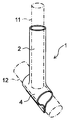
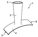
- An embodiment of the protective cover of the present invention is shown, and a perspective view of the protective cover is shown.
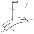
- the perspective view of the state where the protective cover shown in FIG. 1 is attached to the blood vessel anastomosis portion is shown.
- FIG. 1 and 2 show an embodiment of the protective cover of the present invention.
- FIG. 1 shows a perspective view of the protective cover before attaching the protective cover to the blood vessel anastomosis portion
- FIG. 2 shows a perspective view of the protective cover with the protective cover attached to the blood vessel anastomosis portion.
- the first blood vessel and the second blood vessel are indicated by a alternate long and short dash line.
- the protective cover 1 is attached to the anastomotic portion where the first blood vessel 11 is joined to the second blood vessel 12, and covers the outside of the tubular portion 2 and the second blood vessel 12 that cover the outside of the first blood vessel 11. It has a planar portion 4 to cover.
- the first blood vessel 11 and the second blood vessel 12 may be arteries, veins, or artificial blood vessels.
- the anastomosis part includes an end-side anastomosis part in which the end part of the first blood vessel is joined to the side part of the second blood vessel, and the side side where the side part of the first blood vessel and the side part of the second blood vessel are joined.
- anastomosis portion and the like are mentioned, and in the drawing, an example of application to an end-side anastomosis portion in which the end portion of the first blood vessel 11 is joined to the side portion of the second blood vessel 12 is shown.
- an arteriovenous shunt formed as a vascular access that serves as a gateway for blood to be removed from the blood vessel, dialyzed and returned to the blood vessel, the end of the vein is joined to the side of the artery.
- An end-side anastomosis is formed.
- the tubular portion 2 is a portion that covers the first blood vessel 11 and has an axial direction and a circumferential direction.
- the axial direction of the tubular portion 2 corresponds to the extending direction of the first blood vessel 11 when the protective cover 1 is attached to the anastomotic portion.
- the axial length and the circumferential length of the tubular portion 2 are appropriately set according to the size of the first blood vessel 11, and for example, the axial length is in the range of 3 mm to 150 mm and the circumferential length.
- the size can be set in the range of 4 mm to 60 mm.
- the planar portion 4 is a portion that covers the second blood vessel 12, and is formed in a planar shape.
- the first blood vessel 11 is joined to the second blood vessel 12 by suturing or the like, and then the planar portion 4 is wound around the second blood vessel 12, so that the second blood vessel is formed by the planar portion 4. 12 can be covered.
- the planar portion 4 is positioned and fixed around the second blood vessel 12 by joining one side portion and the other side portion of the planar portion 4 wound around the second blood vessel 12 to each other by suturing or the like. be able to.
- the size of the planar portion 4 is appropriately set according to the size of the second blood vessel 12, and for example, the length of the second blood vessel 12 along the extending direction is in the range of 3 mm to 50 mm, and the second blood vessel 12.
- the length of the blood vessel 12 along the circumferential direction can be set in the range of 5 mm to 70 mm.
- the protective cover 1 is configured to include a knitted fabric formed from continuous threads from the tubular portion 2 to the planar portion 4. That is, the protective cover 1 includes a continuous knitted fabric from the tubular portion 2 to the planar portion 4. Since the knitted fabric has excellent elasticity and flexibility, by forming the protective cover 1 from the knitted fabric, the anastomotic portion can be formed without excessively restraining the first blood vessel 11 and the second blood vessel 12 by the protective cover 1. It can be held stably. Therefore, the protective cover 1 appropriately holds the first blood vessel 11 so as to extend in a desired direction starting from the second blood vessel 12, so that the pressure and pulsation of blood at the anastomotic site are desired. Can be controlled to.
- the protective cover 1 prevents damage to blood vessels and tissues around them. Since the protective cover 1 also includes a knitted fabric that is continuous from the tubular portion 2 to the planar portion 4, when the protective cover 1 is attached to the anastomotic portion, an unreasonable force is locally applied to the anastomotic portion. This can be suppressed.
- the anastomotic part is an arteriovenous shunt
- the pressure and beat of arterial blood from the anastomosis part to the vein side is appropriately compressed by the tubular part 2 composed of the knitted fabric to appropriately press the vein serving as the first blood vessel 11. The movement can be gradually suppressed, and the excessive blood flow change of the vein at the initial stage of anastomotic site formation can be alleviated.
- the protective cover 1 has no sewn portion between the tubular portion 2 and the planar portion 4, and the tubular portion 2 and the planar portion 4 also have no sewn portion.
- the tubular portion 2 does not have a sewn portion extending in the axial direction, and the threads constituting the knitted fabric extend continuously in the circumferential direction of the tubular portion 2, that is, the threads forming the knitted fabric It is preferable that it extends spirally while forming a stitch.
- the protective cover 1 is preferably composed entirely of one knitted fabric, that is, the entire protective cover 1 is preferably composed of a knitted fabric formed of continuous yarn.
- the type of knitted fabric is not particularly limited, and may be warp knitting or weft knitting.
- Examples of the warp knitting structure include half knitting, back half knitting, quince coat knitting, and satin knitting.
- Weft knitting includes circular knitting and weft knitting, and examples of the weft knitting structure include flat knitting, rubber knitting, double-sided knitting, Milan rib knitting, and jacquard knitting. From the viewpoint of excellent elasticity, the knitted fabric is preferably composed of weft knitting.
- the knitted fabric When the knitted fabric is composed of weft knitting, the knitted fabric can be formed using a circular knitting machine or a flat knitting machine.
- a flat knitting machine it is preferable to use a WHOLEGARMENT (registered trademark) knitting machine. By using such a knitting machine, it becomes easy to form the tubular portion 2 and the planar portion 4 without a sewn portion, or to continuously form the tubular portion 2 to the planar portion 4 without a sewn portion. ..
- the thread forming the knitted fabric is preferably composed of a biocompatible resin material, for example, a polyolefin resin such as polyethylene and polypropylene, a polyamide resin such as nylon, a polyester resin such as polyethylene terephthalate, and PEEK.
- a biocompatible resin material for example, a polyolefin resin such as polyethylene and polypropylene, a polyamide resin such as nylon, a polyester resin such as polyethylene terephthalate, and PEEK.
- aromatic polyether ketone resins such as, polyether polyamide resins, polyurethane resins, polyimide resins, fluorine resins such as PTFE, PFA and ETFE, synthetic resins such as polyvinyl chloride resins and silicone resins. ..
- the yarn forming the knitted fabric can also be composed of a resin material (for example, polyester, PTFE, polyurethane) used for artificial blood vessels.
- the yarn forming the knitted fabric may be biodegradable.
- the shape of the planar portion 4 is not particularly limited, but it is preferable that the planar portion 4 has a first edge 5 and a second edge 6 provided so as to face each other.
- the planar portion 4 is provided so that the first edge 5 and the second edge 6 extend substantially parallel to the extending direction of the second blood vessel 12.
- the portion of the planar portion 4 on the first edge 5 side and the portion on the second edge 6 side can be easily joined by suturing or the like.
- the first edge 5 and the second edge 6 have straight portions extending substantially parallel to each other.
- the planar portion 4 is preferably formed in a substantially rectangular shape or an oval shape.
- the approximate rectangle also includes a rectangle with rounded corners.
- the oval shape includes an ellipse, a shape in which two semicircles such as a track field are connected by a straight line, an oval shape, and the like. If the planar portion 4 is formed in such a shape, it becomes easy to perform an operation of winding the planar portion 4 around the second blood vessel 12, and the portion of the planar portion 4 on the first edge 5 side and the second portion. When joining the portion on the 6 side of the two end edges by suturing or the like, it becomes easy to increase the joining length.
- the planar portion 4 has a lateral direction, and the lateral direction extends substantially parallel to the extending direction of the second blood vessel 12.
- the lateral direction of the planar portion 4 means the direction in which the length of the planar portion 4 becomes the shortest.
- the lateral direction of the planar portion 4 is preferably a direction perpendicular to the direction from the first edge 5 side to the second edge 6 side.
- the planar portion 4 is formed in a substantially rectangular shape or an oval shape, and the extending direction of the short side of the substantially rectangular shape or the short axis direction of the oval shape is the short side direction.
- the planar portion 4 is composed of one knitted fabric.
- the planar portion 4 may be formed into a desired shape by adjusting the knitting method, and the planar portion 4 may be formed into a desired shape by cutting a part of the knitted fabric after forming the knitted fabric. You may.
- the planar portion 4 is preferably formed in the former mode, that is, the planar portion 4 preferably does not have a cut edge in which a part of the knitted fabric is cut.
- the planar portion 4 may be provided with a reinforcing portion in a part or all of a portion along the peripheral edge.
- Reinforcing parts can form a high knitting density of the knitted fabric of the relevant part, apply resin (for example, adhesive) to the knitted fabric, attach a resin film to the knitted fabric, heat seal the knitted fabric, or the like. It can be formed by welding by ultrasonic welding or the like.
- the reinforcing portion is preferably formed by a high-density portion having a high knitting density of the knitted fabric, which makes it easy to secure the flexibility of the reinforcing portion.
- the planar portion 4 has a high-density portion formed with a high knitting density and a low-density portion formed with a lower knitting density.
- planar portion 4 has a cut edge formed by cutting the knitted fabric, it is also preferable that a reinforcing portion is provided along the cut edge. As a result, the yarn of the knitted fabric constituting the planar portion 4 is less likely to fray starting from the cut end edge.
- the reinforcing portion is provided at least in the portion along the first edge 5 and the portion along the second edge 6.
- the planar portion 4 is provided with reinforcing portions along the first edge 5 and the second edge 6, respectively, and the reinforcing portion along the first edge 5 and the reinforcing portion along the second edge 6.
- Another reinforcing portion may be provided between the two.
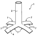
- FIG. 3 shows another embodiment of the protective cover of the present invention.
- the first edge 5 of the planar portion 4 is separated into two, and the second edge 6 is separated into two. That is, the planar portion 4 is separated into two with the first edge 5 as the base point and the second edge 6 as the base point.
- the first edge 5 may be separated into three or more, and the second edge 6 may also be separated into three or more.
- the planar portion 4 is second. It becomes difficult to shift with respect to the blood vessel 12 of the above, and the planar portion 4 can be attached more stably to the second blood vessel 12.
- the first edge 5 may be separated into two or more and the second edge 6 may be separated into two or more by making a notch in the planar portion 4.
- the planar portion 4 may have a shape in which the first edge 5 is separated into two or more and the second edge 6 is separated into two or more. From the viewpoint of preventing the yarn of the knitted fabric constituting the planar portion 4 from fraying and ensuring the flexibility of the planar portion 4, the planar portion 4 is formed into a desired shape by adjusting the knitting method. It is preferable to do so.
- the knitted fabric is formed into a tubular shape, and two or more notches are made from one end edge of the knitted fabric formed in the tubular shape to form a tubular shape.
- the portion 2 and the planar portion 4 can also be formed.
- the planar portion 4 is formed by being separated into two or more, and the planar portion 4 has four or more cutting edges extending in the radial direction of the tubular portion 2 from the connection portion with the tubular portion 2. It becomes a thing. That is, for one notch, two cut edges formed by cutting the knitted fabric are formed.
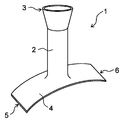
- FIG. 4 shows an example of the protective cover thus formed.
- the shaped portion 4 has a tubular portion 2 and a planar portion 4 formed by making four cuts from one end edge of the knitted fabric formed in a tubular shape.
- the shaped portion 4 has eight cutting edge 7s extending in the radial direction of the tubular portion 2 from the connecting portion with the tubular portion 2.
- the radial direction described here may be a direction extending away from the tubular portion 2 starting from the connecting portion between the planar portion 4 and the tubular portion 2.
- the number of cut edge 7s is preferably 6 or more, more preferably 8 or more, preferably 16 or less, and more preferably 12 or less.
- the tubular portion 2 may be formed to have the same diameter along the axial direction, or may be formed so that the diameter changes along the axial direction.
- the diameter of the tubular portion 2 is formed to be the same along the axial direction.
- the tubular portion 2 may have an end portion 3 having the largest diameter on the side opposite to the side connected to the planar portion 4.
- the tubular portion 2 has a diameter-expanded portion whose diameter increases as the distance from the planar portion 4 increases.
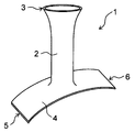
- the tubular portion 2 is formed so that the portion including the end portion 3 on the side opposite to the side connected to the planar portion 4 increases in diameter as the distance from the planar portion 4 increases. Is preferable. If the tubular portion 2 is formed in this way, the first blood vessel 11 can be easily inserted into the tubular portion 2, and after the protective cover 1 is attached to the blood vessel anastomosis portion, the diameter of the tubular portion 2 becomes large. It becomes easy to perform an operation of fixing the widened end portion to another tissue in the vicinity of the first blood vessel 11 by suturing or the like. As a result, after the protective cover 1 is attached to the blood vessel anastomosis portion, the tubular portion 2 can be easily fixed in position without being displaced from the first blood vessel 11.
- the portion formed by expanding the diameter of the tubular portion 2 may be a part or the entire portion of the tubular portion 2 with respect to the axial direction of the tubular portion 2.
- FIGS. 5 and 7 only the end portion 3 of the tubular portion 2 opposite to the side connected to the planar portion 4 is formed so that the diameter increases as the distance from the planar portion 4 increases.
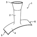
- FIGS. 6 and 8 the entire tubular portion 2 is formed so that the diameter increases as the distance from the planar portion 4 increases. In either case, it is preferable that the end portion 3 on the side opposite to the side connected to the planar portion 4 has the largest diameter.
- the length in the circumferential direction is preferably in the range of, for example, 15 mm to 60 mm.
- the length in the circumferential direction is preferably in the range of, for example, 4 mm to 26 mm.
- the diameter of the tubular portion 2 is such that the portion including the end portion 3 on the side opposite to the side connected to the planar portion 4 increases the angle of the tubular portion 2 with respect to the axial direction as the distance from the planar portion 4 increases. May be spread out and formed. Even if the tubular portion 2 is formed in this way, the operation of inserting the first blood vessel 11 into the tubular portion 2 becomes easy, and after the protective cover 1 is attached to the blood vessel anastomosis portion, the tubular portion 2 is formed. It becomes easy to perform an operation of fixing the end portion having a widened diameter to another tissue in the vicinity of the first blood vessel 11 by suturing or the like.
- FIG. 7 and 8 show an example of the protective cover configured in this way.
- a portion of the tubular portion 2 including the end portion 3 on the side opposite to the side connected to the planar portion 4 is viewed in a cross section along the axial direction of the tubular portion 2. , It is formed so as to spread in a curved shape as the distance from the planar portion 4 increases.
- the portion of the tubular portion 2 including the end portion 3 on the side opposite to the side connected to the planar portion 4 is the planar portion 4 when viewed in a cross section along the axial direction. It is formed so as to spread linearly in multiple stages as it moves away from.
- the second diameter-expanded portion is formed so as to have a second diameter-expanded portion whose diameter increases as the distance from the planar portion 4 increases at an angle B larger than the angle A at a position farther from the planar portion than the first enlarged diameter portion.
- the tubular portion 2 may be formed so as to extend substantially perpendicular to the planar portion 4, or may be formed so as to extend diagonally.
- the angle in the direction in which the tubular portion 2 extends with respect to the planar portion 4 can be appropriately set according to the desired shape of the anastomotic portion.
- the tubular portion 2 preferably extends from the planar portion 4 so as to form an angle of 30 ° or more and 90 ° or less with respect to the planar portion 4, for example.
- the tubular portion 2 has a larger elongation stress in the axial direction than in the circumferential direction.
- the tubular portion 2 easily extends along the circumferential direction, so that the pressure on the first blood vessel 11 by the protective cover 1 can be suppressed, and the first It becomes difficult to inhibit the flexibility of the blood vessel 11 of the blood vessel 11.
- the elongation stress of the tubular portion 2 is measured by extending the tubular portion 2 in the axial direction or the circumferential direction using a tensile tester.
- the tubular portion 2 may be provided with the reinforcing portion described above at the end portion 3 on the side opposite to the side connected to the planar portion 4.
- the tubular portion 2 may be provided with a high-density portion formed with a high knitting density of the knitted fabric as a reinforcing portion.
- the shape of the planar portion 4 of the protective cover 1 shown in FIGS. 5 to 8 is not particularly limited.
- the protective cover 1 shown in FIGS. 5 to 8 may have, for example, a planar portion 4 as shown in FIGS. 3 and 4.
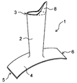
- the protective cover 1 may be provided with a non-cylindrical extending portion 8 at an end portion 3 of the tubular portion 2 opposite to the side connected to the planar portion 4. .
- the extension portion 8 is fixed to another tissue in the vicinity of the first blood vessel 11 by suturing or the like, so that the tubular portion 2 is attached to the first blood vessel 11. It is possible to prevent the position from shifting.
- the extension portion 8 is preferably composed of a knitted fabric, and more preferably is composed of a knitted fabric formed of continuous threads from the tubular portion 2 to the extension portion 8. That is, it is preferable that the protective cover 1 includes a continuous knitted fabric from the tubular portion 2 to the extending portion 8. By forming the extending portion 8 in this way, the flexibility of the protective cover 1 can be increased from the tubular portion 2 to the extending portion 8.
- the shape of the extension portion 8 is not particularly limited.
- the extension portion 8 may be formed into a desired shape by adjusting the knitting method, and the extension portion 8 may be formed into a desired shape by cutting a part of the knitted fabric after forming the knitted fabric. You may.
- the extension portion 8 is preferably formed in the former mode, that is, the extension portion 8 preferably does not have a cut edge in which a part of the knitted fabric is cut. As a result, the yarn of the knitted fabric constituting the extension portion 8 is less likely to fray.
- the shapes of the tubular portion 2 and the planar portion 4 are not particularly limited, and the tubular portion 2 and the planar portion 4 described above may be arbitrarily combined. can.
- the extension portion 8 may be provided with the reinforcing portion described above.
- the extending portion 8 may be provided as a reinforcing portion with a high-density portion formed so that the knitting density of the knitted fabric is higher than that of the tubular portion 2.
- Protective cover 2 Cylindrical part 3: End part on the side opposite to the side connected to the planar part 4: Plane part 5: First edge edge 6: Second edge edge 7: Cut edge edge 8: Extension Exit 11: First blood vessel 12: Second blood vessel
Landscapes
- Health & Medical Sciences (AREA)
- Heart & Thoracic Surgery (AREA)
- Life Sciences & Earth Sciences (AREA)
- Public Health (AREA)
- Surgery (AREA)
- Vascular Medicine (AREA)
- Engineering & Computer Science (AREA)
- Biomedical Technology (AREA)
- Veterinary Medicine (AREA)
- Animal Behavior & Ethology (AREA)
- General Health & Medical Sciences (AREA)
- Anesthesiology (AREA)
- Hematology (AREA)
- Nuclear Medicine, Radiotherapy & Molecular Imaging (AREA)
- Cardiology (AREA)
- Medical Informatics (AREA)
- Molecular Biology (AREA)
- Surgical Instruments (AREA)
- Prostheses (AREA)
- Materials For Medical Uses (AREA)
Priority Applications (3)
| Application Number | Priority Date | Filing Date | Title |
|---|---|---|---|
| JP2022500352A JPWO2021161884A1 (enExample) | 2020-02-14 | 2021-02-04 | |
| CN202180012576.8A CN115052644A (zh) | 2020-02-14 | 2021-02-04 | 血管吻合部的保护套 |
| US17/884,112 US20220378998A1 (en) | 2020-02-14 | 2022-08-09 | Protection cover for anastomotic part |
Applications Claiming Priority (2)
| Application Number | Priority Date | Filing Date | Title |
|---|---|---|---|
| JP2020-023831 | 2020-02-14 | ||
| JP2020023831 | 2020-02-14 |
Related Child Applications (1)
| Application Number | Title | Priority Date | Filing Date |
|---|---|---|---|
| US17/884,112 Continuation US20220378998A1 (en) | 2020-02-14 | 2022-08-09 | Protection cover for anastomotic part |
Publications (1)
| Publication Number | Publication Date |
|---|---|
| WO2021161884A1 true WO2021161884A1 (ja) | 2021-08-19 |
Family
ID=77291828
Family Applications (1)
| Application Number | Title | Priority Date | Filing Date |
|---|---|---|---|
| PCT/JP2021/004062 Ceased WO2021161884A1 (ja) | 2020-02-14 | 2021-02-04 | 血管吻合部の保護カバー |
Country Status (4)
| Country | Link |
|---|---|
| US (1) | US20220378998A1 (enExample) |
| JP (1) | JPWO2021161884A1 (enExample) |
| CN (1) | CN115052644A (enExample) |
| WO (1) | WO2021161884A1 (enExample) |
Cited By (6)
| Publication number | Priority date | Publication date | Assignee | Title |
|---|---|---|---|---|
| CN114795576A (zh) * | 2022-05-05 | 2022-07-29 | 生纳科技(上海)有限公司 | 血管吻合口保护装置 |
| WO2023037861A1 (ja) * | 2021-09-08 | 2023-03-16 | 明郎 萩原 | 血管カバー |
| WO2023037860A1 (ja) * | 2021-09-08 | 2023-03-16 | 明郎 萩原 | 血管カバー |
| WO2023037859A1 (ja) * | 2021-09-08 | 2023-03-16 | 明郎 萩原 | 血管カバー |
| WO2025084409A1 (ja) * | 2023-10-20 | 2025-04-24 | 株式会社彩 | 血管カバー |
| US12310836B2 (en) | 2020-03-03 | 2025-05-27 | Akeo Hagiwara | Vein cover |
Citations (8)
| Publication number | Priority date | Publication date | Assignee | Title |
|---|---|---|---|---|
| US6743243B1 (en) * | 1998-03-20 | 2004-06-01 | Sumit Roy | Support device for endoscopic suturless anastomosis |
| US20080109067A1 (en) * | 1998-11-30 | 2008-05-08 | Imperial College Of Science, Technology & Medicine | Stents for blood vessels |
| JP2008522735A (ja) * | 2004-12-08 | 2008-07-03 | パーバシス セラピューティクス, インコーポレイテッド | 血管アクセスを強化するための方法および組成物 |
| JP2009502226A (ja) * | 2005-07-22 | 2009-01-29 | アーク・セラピューティックス・リミテッド | ステント |
| WO2015061490A1 (en) * | 2013-10-25 | 2015-04-30 | Abbott Cardiovascular Systems Inc. | Extravascular devices supporting an arteriovenous fistula |
| US20160000985A1 (en) * | 2014-07-02 | 2016-01-07 | Abbott Cardiovascular Systems Inc. | Extravascular devices supporting an arteriovenous fistula |
| JP2018126556A (ja) * | 2011-08-01 | 2018-08-16 | ラミネート・メディカル・テクノロジーズ・リミテッド | 外部血管支持体 |
| WO2021010434A1 (ja) * | 2019-07-17 | 2021-01-21 | 国立大学法人東北大学 | 血管矯正器具および吻合部の支持方法 |
Family Cites Families (16)
| Publication number | Priority date | Publication date | Assignee | Title |
|---|---|---|---|---|
| US4474181A (en) * | 1982-02-18 | 1984-10-02 | Schenck Robert R | Method and apparatus for anastomosing small blood vessels |
| EP0895753A1 (en) * | 1997-07-31 | 1999-02-10 | Academisch Ziekenhuis Utrecht | Temporary vascular seal for anastomosis |
| US20050084514A1 (en) * | 2000-11-06 | 2005-04-21 | Afmedica, Inc. | Combination drug therapy for reducing scar tissue formation |
| DE10137414B4 (de) * | 2001-07-31 | 2005-12-29 | Aesculap Ag & Co. Kg | Ummantelung für Venen und Verwendung in der Chirurgie |
| ITMO20020337A1 (it) * | 2002-11-21 | 2004-05-22 | G A M A H S Srl | Dispositivo per anastomosi. |
| US20050149073A1 (en) * | 2003-12-17 | 2005-07-07 | Arani Djavad T. | Mechanisms and methods used in the anastomosis of biological conduits |
| US20100070019A1 (en) * | 2006-10-29 | 2010-03-18 | Aneuwrap Ltd. | extra-vascular wrapping for treating aneurysmatic aorta and methods thereof |
| DE102007060497A1 (de) * | 2007-12-06 | 2009-06-10 | Joline Gmbh & Co. Kg | Implantierbare Gefäßstütze |
| DE102008052837A1 (de) * | 2008-10-13 | 2010-04-15 | Aesculap Ag | Textiles Implantat mit Kern-Mantel-Aufbau und Verfahren zu seiner Herstellung |
| US20120078293A1 (en) * | 2009-03-27 | 2012-03-29 | Technion Research & Development Foundation Ltd. | Applicators for patches and adhesives |
| EP2528537A4 (en) * | 2010-01-27 | 2016-09-07 | Vascular Therapies Inc | DEVICE AND METHOD FOR STENOSIS PREVENTION AT AN ANASTOMOSE STATION |
| EP2877220B1 (en) * | 2012-08-01 | 2017-01-04 | Laminate Medical Technologies Ltd | Apparatus for configuring an arteriovenous fistula |
| CN104338187B (zh) * | 2013-08-06 | 2016-12-28 | 北京精密机电控制设备研究所 | 人造血管保护套以及包括这种保护套的人造血管保护装置 |
| CN204133649U (zh) * | 2014-09-04 | 2015-02-04 | 浙江省人民医院 | 一种医用血管外支架 |
| CN206424424U (zh) * | 2016-10-31 | 2017-08-22 | 黄剑 | 基于血循环临时复通使用的桥接支架 |
| US20190247051A1 (en) * | 2018-02-15 | 2019-08-15 | Fareed Siddiqui | Active textile endograft |
-
2021
- 2021-02-04 WO PCT/JP2021/004062 patent/WO2021161884A1/ja not_active Ceased
- 2021-02-04 CN CN202180012576.8A patent/CN115052644A/zh active Pending
- 2021-02-04 JP JP2022500352A patent/JPWO2021161884A1/ja active Pending
-
2022
- 2022-08-09 US US17/884,112 patent/US20220378998A1/en not_active Abandoned
Patent Citations (8)
| Publication number | Priority date | Publication date | Assignee | Title |
|---|---|---|---|---|
| US6743243B1 (en) * | 1998-03-20 | 2004-06-01 | Sumit Roy | Support device for endoscopic suturless anastomosis |
| US20080109067A1 (en) * | 1998-11-30 | 2008-05-08 | Imperial College Of Science, Technology & Medicine | Stents for blood vessels |
| JP2008522735A (ja) * | 2004-12-08 | 2008-07-03 | パーバシス セラピューティクス, インコーポレイテッド | 血管アクセスを強化するための方法および組成物 |
| JP2009502226A (ja) * | 2005-07-22 | 2009-01-29 | アーク・セラピューティックス・リミテッド | ステント |
| JP2018126556A (ja) * | 2011-08-01 | 2018-08-16 | ラミネート・メディカル・テクノロジーズ・リミテッド | 外部血管支持体 |
| WO2015061490A1 (en) * | 2013-10-25 | 2015-04-30 | Abbott Cardiovascular Systems Inc. | Extravascular devices supporting an arteriovenous fistula |
| US20160000985A1 (en) * | 2014-07-02 | 2016-01-07 | Abbott Cardiovascular Systems Inc. | Extravascular devices supporting an arteriovenous fistula |
| WO2021010434A1 (ja) * | 2019-07-17 | 2021-01-21 | 国立大学法人東北大学 | 血管矯正器具および吻合部の支持方法 |
Cited By (6)
| Publication number | Priority date | Publication date | Assignee | Title |
|---|---|---|---|---|
| US12310836B2 (en) | 2020-03-03 | 2025-05-27 | Akeo Hagiwara | Vein cover |
| WO2023037861A1 (ja) * | 2021-09-08 | 2023-03-16 | 明郎 萩原 | 血管カバー |
| WO2023037860A1 (ja) * | 2021-09-08 | 2023-03-16 | 明郎 萩原 | 血管カバー |
| WO2023037859A1 (ja) * | 2021-09-08 | 2023-03-16 | 明郎 萩原 | 血管カバー |
| CN114795576A (zh) * | 2022-05-05 | 2022-07-29 | 生纳科技(上海)有限公司 | 血管吻合口保护装置 |
| WO2025084409A1 (ja) * | 2023-10-20 | 2025-04-24 | 株式会社彩 | 血管カバー |
Also Published As
| Publication number | Publication date |
|---|---|
| US20220378998A1 (en) | 2022-12-01 |
| CN115052644A (zh) | 2022-09-13 |
| JPWO2021161884A1 (enExample) | 2021-08-19 |
Similar Documents
| Publication | Publication Date | Title |
|---|---|---|
| WO2021161884A1 (ja) | 血管吻合部の保護カバー | |
| US20230201013A1 (en) | Self-sealing tubular grafts, patches, and methods for making and using them | |
| JP5837568B2 (ja) | ストーマ安定化器具および方法 | |
| EP3351209B1 (en) | Graft anchor device | |
| US20100070019A1 (en) | extra-vascular wrapping for treating aneurysmatic aorta and methods thereof | |
| JP7624235B2 (ja) | 静脈カバー | |
| US10064625B2 (en) | Connector | |
| US10850084B1 (en) | Arteriovenous graft and method of providing dialysis | |
| US12310836B2 (en) | Vein cover | |
| JP3568756B2 (ja) | 人工血管用接続具 | |
| US20240366362A1 (en) | Blood vessel cover | |
| US20060004391A1 (en) | Means for connecting blood vessels (connector of blood vessels, grafts and/or prostheses) | |
| WO2023037861A1 (ja) | 血管カバー | |
| US20240366361A1 (en) | Blood vessel cover | |
| CN101686833B (zh) | 脉管连接器和用于外科的具有施用器的试剂盒 | |
| JP6765613B2 (ja) | 脱血導管アセンブリ | |
| US20240138837A1 (en) | Anastomotic device | |
| WO2025084409A1 (ja) | 血管カバー | |
| JP2024123908A (ja) | バスキュラーアクセス装置、およびバスキュラーアクセス構造 | |
| US10335264B2 (en) | Vascular graft | |
| JP2023163879A (ja) | 固定構造 | |
| US8828030B2 (en) | Insertable prosthesis and prosthesis board for anastomosis | |
| JP2021013405A (ja) | 血管内留置具接続構造及び血管内留置システム |
Legal Events
| Date | Code | Title | Description |
|---|---|---|---|
| 121 | Ep: the epo has been informed by wipo that ep was designated in this application |
Ref document number: 21752918 Country of ref document: EP Kind code of ref document: A1 |
|
| ENP | Entry into the national phase |
Ref document number: 2022500352 Country of ref document: JP Kind code of ref document: A |
|
| NENP | Non-entry into the national phase |
Ref country code: DE |
|
| 122 | Ep: pct application non-entry in european phase |
Ref document number: 21752918 Country of ref document: EP Kind code of ref document: A1 |