WO2021161884A1 - Protective cover for vascular anastomotic site - Google Patents
Protective cover for vascular anastomotic site Download PDFInfo
- Publication number
- WO2021161884A1 WO2021161884A1 PCT/JP2021/004062 JP2021004062W WO2021161884A1 WO 2021161884 A1 WO2021161884 A1 WO 2021161884A1 JP 2021004062 W JP2021004062 W JP 2021004062W WO 2021161884 A1 WO2021161884 A1 WO 2021161884A1
- Authority
- WO
- WIPO (PCT)
- Prior art keywords
- protective cover
- edge
- blood vessel
- planar portion
- planar
- Prior art date
Links
Images

Classifications
-
- A—HUMAN NECESSITIES
- A61—MEDICAL OR VETERINARY SCIENCE; HYGIENE
- A61M—DEVICES FOR INTRODUCING MEDIA INTO, OR ONTO, THE BODY; DEVICES FOR TRANSDUCING BODY MEDIA OR FOR TAKING MEDIA FROM THE BODY; DEVICES FOR PRODUCING OR ENDING SLEEP OR STUPOR
- A61M1/00—Suction or pumping devices for medical purposes; Devices for carrying-off, for treatment of, or for carrying-over, body-liquids; Drainage systems
- A61M1/36—Other treatment of blood in a by-pass of the natural circulatory system, e.g. temperature adaptation, irradiation ; Extra-corporeal blood circuits
- A61M1/3621—Extra-corporeal blood circuits
- A61M1/3653—Interfaces between patient blood circulation and extra-corporal blood circuit
- A61M1/3655—Arterio-venous shunts or fistulae
-
- A—HUMAN NECESSITIES
- A61—MEDICAL OR VETERINARY SCIENCE; HYGIENE
- A61B—DIAGNOSIS; SURGERY; IDENTIFICATION
- A61B17/00—Surgical instruments, devices or methods, e.g. tourniquets
- A61B17/11—Surgical instruments, devices or methods, e.g. tourniquets for performing anastomosis; Buttons for anastomosis
- A61B2017/1107—Surgical instruments, devices or methods, e.g. tourniquets for performing anastomosis; Buttons for anastomosis for blood vessels
-
- A—HUMAN NECESSITIES
- A61—MEDICAL OR VETERINARY SCIENCE; HYGIENE
- A61B—DIAGNOSIS; SURGERY; IDENTIFICATION
- A61B17/00—Surgical instruments, devices or methods, e.g. tourniquets
- A61B17/11—Surgical instruments, devices or methods, e.g. tourniquets for performing anastomosis; Buttons for anastomosis
- A61B2017/1135—End-to-side connections, e.g. T- or Y-connections
-
- A—HUMAN NECESSITIES
- A61—MEDICAL OR VETERINARY SCIENCE; HYGIENE
- A61F—FILTERS IMPLANTABLE INTO BLOOD VESSELS; PROSTHESES; DEVICES PROVIDING PATENCY TO, OR PREVENTING COLLAPSING OF, TUBULAR STRUCTURES OF THE BODY, e.g. STENTS; ORTHOPAEDIC, NURSING OR CONTRACEPTIVE DEVICES; FOMENTATION; TREATMENT OR PROTECTION OF EYES OR EARS; BANDAGES, DRESSINGS OR ABSORBENT PADS; FIRST-AID KITS
- A61F2/00—Filters implantable into blood vessels; Prostheses, i.e. artificial substitutes or replacements for parts of the body; Appliances for connecting them with the body; Devices providing patency to, or preventing collapsing of, tubular structures of the body, e.g. stents
- A61F2/02—Prostheses implantable into the body
- A61F2/04—Hollow or tubular parts of organs, e.g. bladders, tracheae, bronchi or bile ducts
- A61F2/06—Blood vessels
- A61F2/064—Blood vessels with special features to facilitate anastomotic coupling
Definitions
- the present invention relates to a protective cover for a vascular anastomosis, for example, a protective cover that can be installed on an arteriovenous shunt.
- dialysis treatment is regularly performed to remove blood from the patient's body, remove waste products, excess water, minerals, etc. with a dialyzer, and then return it to the patient's body.
- a vascular access serves as a gateway for blood to be taken out of the blood vessel and returned to the blood vessel, so that a large amount of blood can pass through the arteries and veins.
- the arteriovenous shunt may be prepared on the patient's forearm or the like. In such an arteriovenous shunt, for example, an end-side anastomosis is formed in which the end of the vein is joined to the side of the artery.
- anastomosis is caused by excessive force applied to the anastomotic site, disturbance of the blood flow through the anastomotic site, and sudden changes in blood pressure and blood circulation on the venous side.
- Excessive pressure changes to the blood vessel wall occur in the veins and veins downstream of the vein, resulting in excessive stress in the blood vessel wall, leading to pathological intimal thickening, causing obstruction and stenosis. May occur.
- Patent Document 1 is a device for forming a first blood vessel and a second blood vessel connected by anastomosis, which has a coupler and a sleeve, and the coupler is placed on the first blood vessel.
- Disclosed is a device configured such that the sleeve is connected to an adapter and is configured to surround and hold a portion of a second blood vessel such that a first blood vessel and a second blood vessel are joined at a sharp angle. Has been done.
- Patent Document 2 describes an external vascular support that forms a junction between an artery and a vein anastomosed to the artery, the support being connected to an arterial portion that connects to the artery and to the vein. It is provided with a venous portion, the arterial portion and the venous portion are connected at a sharp angle at the joint, and the sharp angle is rounded, and the vascular support is a fillet between the vein and the artery.
- an external vascular support shaped to form a vein and maintain a sharp angle to the artery.
- anastomotic site As described above, various protective covers for the anastomotic site have been conventionally proposed, but in the anastomotic site, the anastomotic site is stably held while the protective cover does not excessively restrain the movement of the blood vessel. Is desired.
- the present invention has been made in view of the above circumstances, and an object of the present invention is to provide a protective cover capable of stably holding the anastomotic portion while not excessively restricting the movement of blood vessels at the anastomotic portion. There is.
- the protective cover of the present invention that has been able to solve the above problems is a protective cover for an anastomotic portion in which a first blood vessel is joined to a second blood vessel, and the protective cover covers the outside of the first blood vessel. It has a tubular portion and a planar portion that covers the outside of the second blood vessel, and is characterized in that it is composed of a knitted fabric formed from continuous threads from the tubular portion to the planar portion.
- the protective cover is formed from the knitted fabric to stably hold the anastomotic part without excessively restraining the first blood vessel and the second blood vessel by the protective cover. can do. Therefore, the protective cover appropriately holds the first blood vessel so as to extend in a desired direction starting from the second blood vessel, and controls the pressure and pulsation of blood at the anastomotic site as desired. be able to. In addition, the protective cover prevents damage to blood vessels and surrounding tissues.
- the protective cover also includes a continuous knitted fabric from the tubular part to the planar part, so that when the protective cover is attached to the anastomotic part, an excessive force is locally applied to the anastomotic part. Be done.
- the pressure and pulsation of arterial blood from the anastomosis part to the vein side is applied by appropriately compressing the vein that becomes the first blood vessel with the tubular part composed of the knitted fabric. It can be gradually suppressed, and excessive changes in blood flow in veins at the initial stage of anastomotic formation can be alleviated.
- the tubular portion has a larger elongation stress in the axial direction than in the circumferential direction.
- the flexibility of the first blood vessel is less likely to be impaired by the protective cover.
- tubular portion and the planar portion do not have a sewn portion.
- the planar portion is formed in a substantially rectangular shape or an oval shape. Further, it is preferable that the planar portion has a lateral direction, and the lateral direction extends substantially parallel to the extending direction of the second blood vessel.
- the tubular portion is formed so that the portion including the end portion on the side opposite to the side connected to the planar portion has a wider diameter as the distance from the planar portion increases.
- the tubular portion is formed so that the portion including the end portion on the side opposite to the side connected to the planar portion has a wider diameter so that the angle of the tubular portion with respect to the axial direction increases as the distance from the planar portion increases. You may.
- the tubular portion is located at a position of a first enlarged diameter portion whose diameter increases as it is separated from the planar portion at an angle A with respect to the axial direction of the tubular portion and a position farther from the planar portion than the first enlarged diameter portion. It has a second enlarged diameter portion whose diameter increases as it moves away from the planar portion at an angle B larger than the angle A, and the end portion on the side opposite to the side connected to the planar portion has the largest diameter. May be good.
- a non-cylindrical extension may be provided at the end of the tubular portion on the side opposite to the side connected to the planar portion.
- the extending portion includes a knitted fabric formed of continuous threads from the tubular portion to the extending portion.
- the planar portion has a first edge and a second edge provided so as to face each other, and the first edge is separated into two or more and the second edge is separated into two or more. You may.
- the planar portion has a cut edge formed by cutting the knitted fabric, and a reinforcing portion may be provided along the cut edge.
- the planar portion has a first edge and a second edge provided so as to face each other, and the planar portion is provided with a reinforcing portion along the first edge and the second edge, respectively.
- Another reinforcing portion may be provided between the reinforcing portion along the first edge and the reinforcing portion along the second edge.
- the planar portion may have four or more cut edges formed by cutting the knitted fabric so as to extend in the radial direction of the tubular portion from the connection portion with the tubular portion.
- the anastomotic portion can be stably held without excessively restraining the first blood vessel and the second blood vessel. Therefore, the protective cover appropriately holds the first blood vessel so as to extend in a desired direction starting from the second blood vessel, and controls the pressure and pulsation of blood at the anastomotic site as desired. be able to.
- the protective cover prevents damage to blood vessels and surrounding tissues.
- the protective cover also includes a continuous knitted fabric from the tubular part to the planar part, so that when the protective cover is attached to the anastomotic part, an excessive force is locally applied to the anastomotic part. Be done.
- the pressure and pulsation of arterial blood from the anastomosis part to the vein side is applied by appropriately compressing the vein that becomes the first blood vessel with the tubular part composed of the knitted fabric. It can be gradually suppressed, and excessive changes in blood flow in veins at the initial stage of anastomotic formation can be alleviated.
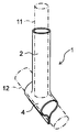
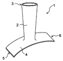
- An embodiment of the protective cover of the present invention is shown, and a perspective view of the protective cover is shown.
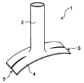
- the perspective view of the state where the protective cover shown in FIG. 1 is attached to the blood vessel anastomosis portion is shown.
- FIG. 1 and 2 show an embodiment of the protective cover of the present invention.
- FIG. 1 shows a perspective view of the protective cover before attaching the protective cover to the blood vessel anastomosis portion
- FIG. 2 shows a perspective view of the protective cover with the protective cover attached to the blood vessel anastomosis portion.
- the first blood vessel and the second blood vessel are indicated by a alternate long and short dash line.
- the protective cover 1 is attached to the anastomotic portion where the first blood vessel 11 is joined to the second blood vessel 12, and covers the outside of the tubular portion 2 and the second blood vessel 12 that cover the outside of the first blood vessel 11. It has a planar portion 4 to cover.
- the first blood vessel 11 and the second blood vessel 12 may be arteries, veins, or artificial blood vessels.
- the anastomosis part includes an end-side anastomosis part in which the end part of the first blood vessel is joined to the side part of the second blood vessel, and the side side where the side part of the first blood vessel and the side part of the second blood vessel are joined.
- anastomosis portion and the like are mentioned, and in the drawing, an example of application to an end-side anastomosis portion in which the end portion of the first blood vessel 11 is joined to the side portion of the second blood vessel 12 is shown.
- an arteriovenous shunt formed as a vascular access that serves as a gateway for blood to be removed from the blood vessel, dialyzed and returned to the blood vessel, the end of the vein is joined to the side of the artery.
- An end-side anastomosis is formed.
- the tubular portion 2 is a portion that covers the first blood vessel 11 and has an axial direction and a circumferential direction.
- the axial direction of the tubular portion 2 corresponds to the extending direction of the first blood vessel 11 when the protective cover 1 is attached to the anastomotic portion.
- the axial length and the circumferential length of the tubular portion 2 are appropriately set according to the size of the first blood vessel 11, and for example, the axial length is in the range of 3 mm to 150 mm and the circumferential length.
- the size can be set in the range of 4 mm to 60 mm.
- the planar portion 4 is a portion that covers the second blood vessel 12, and is formed in a planar shape.
- the first blood vessel 11 is joined to the second blood vessel 12 by suturing or the like, and then the planar portion 4 is wound around the second blood vessel 12, so that the second blood vessel is formed by the planar portion 4. 12 can be covered.
- the planar portion 4 is positioned and fixed around the second blood vessel 12 by joining one side portion and the other side portion of the planar portion 4 wound around the second blood vessel 12 to each other by suturing or the like. be able to.
- the size of the planar portion 4 is appropriately set according to the size of the second blood vessel 12, and for example, the length of the second blood vessel 12 along the extending direction is in the range of 3 mm to 50 mm, and the second blood vessel 12.
- the length of the blood vessel 12 along the circumferential direction can be set in the range of 5 mm to 70 mm.
- the protective cover 1 is configured to include a knitted fabric formed from continuous threads from the tubular portion 2 to the planar portion 4. That is, the protective cover 1 includes a continuous knitted fabric from the tubular portion 2 to the planar portion 4. Since the knitted fabric has excellent elasticity and flexibility, by forming the protective cover 1 from the knitted fabric, the anastomotic portion can be formed without excessively restraining the first blood vessel 11 and the second blood vessel 12 by the protective cover 1. It can be held stably. Therefore, the protective cover 1 appropriately holds the first blood vessel 11 so as to extend in a desired direction starting from the second blood vessel 12, so that the pressure and pulsation of blood at the anastomotic site are desired. Can be controlled to.
- the protective cover 1 prevents damage to blood vessels and tissues around them. Since the protective cover 1 also includes a knitted fabric that is continuous from the tubular portion 2 to the planar portion 4, when the protective cover 1 is attached to the anastomotic portion, an unreasonable force is locally applied to the anastomotic portion. This can be suppressed.
- the anastomotic part is an arteriovenous shunt
- the pressure and beat of arterial blood from the anastomosis part to the vein side is appropriately compressed by the tubular part 2 composed of the knitted fabric to appropriately press the vein serving as the first blood vessel 11. The movement can be gradually suppressed, and the excessive blood flow change of the vein at the initial stage of anastomotic site formation can be alleviated.
- the protective cover 1 has no sewn portion between the tubular portion 2 and the planar portion 4, and the tubular portion 2 and the planar portion 4 also have no sewn portion.
- the tubular portion 2 does not have a sewn portion extending in the axial direction, and the threads constituting the knitted fabric extend continuously in the circumferential direction of the tubular portion 2, that is, the threads forming the knitted fabric It is preferable that it extends spirally while forming a stitch.
- the protective cover 1 is preferably composed entirely of one knitted fabric, that is, the entire protective cover 1 is preferably composed of a knitted fabric formed of continuous yarn.
- the type of knitted fabric is not particularly limited, and may be warp knitting or weft knitting.
- Examples of the warp knitting structure include half knitting, back half knitting, quince coat knitting, and satin knitting.
- Weft knitting includes circular knitting and weft knitting, and examples of the weft knitting structure include flat knitting, rubber knitting, double-sided knitting, Milan rib knitting, and jacquard knitting. From the viewpoint of excellent elasticity, the knitted fabric is preferably composed of weft knitting.
- the knitted fabric When the knitted fabric is composed of weft knitting, the knitted fabric can be formed using a circular knitting machine or a flat knitting machine.
- a flat knitting machine it is preferable to use a WHOLEGARMENT (registered trademark) knitting machine. By using such a knitting machine, it becomes easy to form the tubular portion 2 and the planar portion 4 without a sewn portion, or to continuously form the tubular portion 2 to the planar portion 4 without a sewn portion. ..
- the thread forming the knitted fabric is preferably composed of a biocompatible resin material, for example, a polyolefin resin such as polyethylene and polypropylene, a polyamide resin such as nylon, a polyester resin such as polyethylene terephthalate, and PEEK.
- a biocompatible resin material for example, a polyolefin resin such as polyethylene and polypropylene, a polyamide resin such as nylon, a polyester resin such as polyethylene terephthalate, and PEEK.
- aromatic polyether ketone resins such as, polyether polyamide resins, polyurethane resins, polyimide resins, fluorine resins such as PTFE, PFA and ETFE, synthetic resins such as polyvinyl chloride resins and silicone resins. ..
- the yarn forming the knitted fabric can also be composed of a resin material (for example, polyester, PTFE, polyurethane) used for artificial blood vessels.
- the yarn forming the knitted fabric may be biodegradable.
- the shape of the planar portion 4 is not particularly limited, but it is preferable that the planar portion 4 has a first edge 5 and a second edge 6 provided so as to face each other.
- the planar portion 4 is provided so that the first edge 5 and the second edge 6 extend substantially parallel to the extending direction of the second blood vessel 12.
- the portion of the planar portion 4 on the first edge 5 side and the portion on the second edge 6 side can be easily joined by suturing or the like.
- the first edge 5 and the second edge 6 have straight portions extending substantially parallel to each other.
- the planar portion 4 is preferably formed in a substantially rectangular shape or an oval shape.
- the approximate rectangle also includes a rectangle with rounded corners.
- the oval shape includes an ellipse, a shape in which two semicircles such as a track field are connected by a straight line, an oval shape, and the like. If the planar portion 4 is formed in such a shape, it becomes easy to perform an operation of winding the planar portion 4 around the second blood vessel 12, and the portion of the planar portion 4 on the first edge 5 side and the second portion. When joining the portion on the 6 side of the two end edges by suturing or the like, it becomes easy to increase the joining length.
- the planar portion 4 has a lateral direction, and the lateral direction extends substantially parallel to the extending direction of the second blood vessel 12.
- the lateral direction of the planar portion 4 means the direction in which the length of the planar portion 4 becomes the shortest.
- the lateral direction of the planar portion 4 is preferably a direction perpendicular to the direction from the first edge 5 side to the second edge 6 side.
- the planar portion 4 is formed in a substantially rectangular shape or an oval shape, and the extending direction of the short side of the substantially rectangular shape or the short axis direction of the oval shape is the short side direction.
- the planar portion 4 is composed of one knitted fabric.
- the planar portion 4 may be formed into a desired shape by adjusting the knitting method, and the planar portion 4 may be formed into a desired shape by cutting a part of the knitted fabric after forming the knitted fabric. You may.
- the planar portion 4 is preferably formed in the former mode, that is, the planar portion 4 preferably does not have a cut edge in which a part of the knitted fabric is cut.
- the planar portion 4 may be provided with a reinforcing portion in a part or all of a portion along the peripheral edge.
- Reinforcing parts can form a high knitting density of the knitted fabric of the relevant part, apply resin (for example, adhesive) to the knitted fabric, attach a resin film to the knitted fabric, heat seal the knitted fabric, or the like. It can be formed by welding by ultrasonic welding or the like.
- the reinforcing portion is preferably formed by a high-density portion having a high knitting density of the knitted fabric, which makes it easy to secure the flexibility of the reinforcing portion.
- the planar portion 4 has a high-density portion formed with a high knitting density and a low-density portion formed with a lower knitting density.
- planar portion 4 has a cut edge formed by cutting the knitted fabric, it is also preferable that a reinforcing portion is provided along the cut edge. As a result, the yarn of the knitted fabric constituting the planar portion 4 is less likely to fray starting from the cut end edge.
- the reinforcing portion is provided at least in the portion along the first edge 5 and the portion along the second edge 6.
- the planar portion 4 is provided with reinforcing portions along the first edge 5 and the second edge 6, respectively, and the reinforcing portion along the first edge 5 and the reinforcing portion along the second edge 6.
- Another reinforcing portion may be provided between the two.
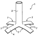
- FIG. 3 shows another embodiment of the protective cover of the present invention.
- the first edge 5 of the planar portion 4 is separated into two, and the second edge 6 is separated into two. That is, the planar portion 4 is separated into two with the first edge 5 as the base point and the second edge 6 as the base point.
- the first edge 5 may be separated into three or more, and the second edge 6 may also be separated into three or more.
- the planar portion 4 is second. It becomes difficult to shift with respect to the blood vessel 12 of the above, and the planar portion 4 can be attached more stably to the second blood vessel 12.
- the first edge 5 may be separated into two or more and the second edge 6 may be separated into two or more by making a notch in the planar portion 4.
- the planar portion 4 may have a shape in which the first edge 5 is separated into two or more and the second edge 6 is separated into two or more. From the viewpoint of preventing the yarn of the knitted fabric constituting the planar portion 4 from fraying and ensuring the flexibility of the planar portion 4, the planar portion 4 is formed into a desired shape by adjusting the knitting method. It is preferable to do so.
- the knitted fabric is formed into a tubular shape, and two or more notches are made from one end edge of the knitted fabric formed in the tubular shape to form a tubular shape.
- the portion 2 and the planar portion 4 can also be formed.
- the planar portion 4 is formed by being separated into two or more, and the planar portion 4 has four or more cutting edges extending in the radial direction of the tubular portion 2 from the connection portion with the tubular portion 2. It becomes a thing. That is, for one notch, two cut edges formed by cutting the knitted fabric are formed.
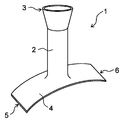
- FIG. 4 shows an example of the protective cover thus formed.
- the shaped portion 4 has a tubular portion 2 and a planar portion 4 formed by making four cuts from one end edge of the knitted fabric formed in a tubular shape.
- the shaped portion 4 has eight cutting edge 7s extending in the radial direction of the tubular portion 2 from the connecting portion with the tubular portion 2.
- the radial direction described here may be a direction extending away from the tubular portion 2 starting from the connecting portion between the planar portion 4 and the tubular portion 2.
- the number of cut edge 7s is preferably 6 or more, more preferably 8 or more, preferably 16 or less, and more preferably 12 or less.
- the tubular portion 2 may be formed to have the same diameter along the axial direction, or may be formed so that the diameter changes along the axial direction.
- the diameter of the tubular portion 2 is formed to be the same along the axial direction.
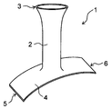
- the tubular portion 2 may have an end portion 3 having the largest diameter on the side opposite to the side connected to the planar portion 4.
- the tubular portion 2 has a diameter-expanded portion whose diameter increases as the distance from the planar portion 4 increases.
- the tubular portion 2 is formed so that the portion including the end portion 3 on the side opposite to the side connected to the planar portion 4 increases in diameter as the distance from the planar portion 4 increases. Is preferable. If the tubular portion 2 is formed in this way, the first blood vessel 11 can be easily inserted into the tubular portion 2, and after the protective cover 1 is attached to the blood vessel anastomosis portion, the diameter of the tubular portion 2 becomes large. It becomes easy to perform an operation of fixing the widened end portion to another tissue in the vicinity of the first blood vessel 11 by suturing or the like. As a result, after the protective cover 1 is attached to the blood vessel anastomosis portion, the tubular portion 2 can be easily fixed in position without being displaced from the first blood vessel 11.
- the portion formed by expanding the diameter of the tubular portion 2 may be a part or the entire portion of the tubular portion 2 with respect to the axial direction of the tubular portion 2.
- FIGS. 5 and 7 only the end portion 3 of the tubular portion 2 opposite to the side connected to the planar portion 4 is formed so that the diameter increases as the distance from the planar portion 4 increases.
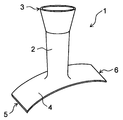
- FIGS. 6 and 8 the entire tubular portion 2 is formed so that the diameter increases as the distance from the planar portion 4 increases. In either case, it is preferable that the end portion 3 on the side opposite to the side connected to the planar portion 4 has the largest diameter.
- the length in the circumferential direction is preferably in the range of, for example, 15 mm to 60 mm.
- the length in the circumferential direction is preferably in the range of, for example, 4 mm to 26 mm.
- the diameter of the tubular portion 2 is such that the portion including the end portion 3 on the side opposite to the side connected to the planar portion 4 increases the angle of the tubular portion 2 with respect to the axial direction as the distance from the planar portion 4 increases. May be spread out and formed. Even if the tubular portion 2 is formed in this way, the operation of inserting the first blood vessel 11 into the tubular portion 2 becomes easy, and after the protective cover 1 is attached to the blood vessel anastomosis portion, the tubular portion 2 is formed. It becomes easy to perform an operation of fixing the end portion having a widened diameter to another tissue in the vicinity of the first blood vessel 11 by suturing or the like.
- FIG. 7 and 8 show an example of the protective cover configured in this way.
- a portion of the tubular portion 2 including the end portion 3 on the side opposite to the side connected to the planar portion 4 is viewed in a cross section along the axial direction of the tubular portion 2. , It is formed so as to spread in a curved shape as the distance from the planar portion 4 increases.
- the portion of the tubular portion 2 including the end portion 3 on the side opposite to the side connected to the planar portion 4 is the planar portion 4 when viewed in a cross section along the axial direction. It is formed so as to spread linearly in multiple stages as it moves away from.
- the second diameter-expanded portion is formed so as to have a second diameter-expanded portion whose diameter increases as the distance from the planar portion 4 increases at an angle B larger than the angle A at a position farther from the planar portion than the first enlarged diameter portion.
- the tubular portion 2 may be formed so as to extend substantially perpendicular to the planar portion 4, or may be formed so as to extend diagonally.
- the angle in the direction in which the tubular portion 2 extends with respect to the planar portion 4 can be appropriately set according to the desired shape of the anastomotic portion.
- the tubular portion 2 preferably extends from the planar portion 4 so as to form an angle of 30 ° or more and 90 ° or less with respect to the planar portion 4, for example.
- the tubular portion 2 has a larger elongation stress in the axial direction than in the circumferential direction.
- the tubular portion 2 easily extends along the circumferential direction, so that the pressure on the first blood vessel 11 by the protective cover 1 can be suppressed, and the first It becomes difficult to inhibit the flexibility of the blood vessel 11 of the blood vessel 11.
- the elongation stress of the tubular portion 2 is measured by extending the tubular portion 2 in the axial direction or the circumferential direction using a tensile tester.
- the tubular portion 2 may be provided with the reinforcing portion described above at the end portion 3 on the side opposite to the side connected to the planar portion 4.
- the tubular portion 2 may be provided with a high-density portion formed with a high knitting density of the knitted fabric as a reinforcing portion.
- the shape of the planar portion 4 of the protective cover 1 shown in FIGS. 5 to 8 is not particularly limited.
- the protective cover 1 shown in FIGS. 5 to 8 may have, for example, a planar portion 4 as shown in FIGS. 3 and 4.
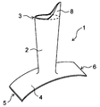
- the protective cover 1 may be provided with a non-cylindrical extending portion 8 at an end portion 3 of the tubular portion 2 opposite to the side connected to the planar portion 4. .
- the extension portion 8 is fixed to another tissue in the vicinity of the first blood vessel 11 by suturing or the like, so that the tubular portion 2 is attached to the first blood vessel 11. It is possible to prevent the position from shifting.
- the extension portion 8 is preferably composed of a knitted fabric, and more preferably is composed of a knitted fabric formed of continuous threads from the tubular portion 2 to the extension portion 8. That is, it is preferable that the protective cover 1 includes a continuous knitted fabric from the tubular portion 2 to the extending portion 8. By forming the extending portion 8 in this way, the flexibility of the protective cover 1 can be increased from the tubular portion 2 to the extending portion 8.
- the shape of the extension portion 8 is not particularly limited.
- the extension portion 8 may be formed into a desired shape by adjusting the knitting method, and the extension portion 8 may be formed into a desired shape by cutting a part of the knitted fabric after forming the knitted fabric. You may.
- the extension portion 8 is preferably formed in the former mode, that is, the extension portion 8 preferably does not have a cut edge in which a part of the knitted fabric is cut. As a result, the yarn of the knitted fabric constituting the extension portion 8 is less likely to fray.
- the shapes of the tubular portion 2 and the planar portion 4 are not particularly limited, and the tubular portion 2 and the planar portion 4 described above may be arbitrarily combined. can.
- the extension portion 8 may be provided with the reinforcing portion described above.
- the extending portion 8 may be provided as a reinforcing portion with a high-density portion formed so that the knitting density of the knitted fabric is higher than that of the tubular portion 2.
- Protective cover 2 Cylindrical part 3: End part on the side opposite to the side connected to the planar part 4: Plane part 5: First edge edge 6: Second edge edge 7: Cut edge edge 8: Extension Exit 11: First blood vessel 12: Second blood vessel
Abstract
This protective cover (1) for an anastomotic site where a first blood vessel is joined to a second blood vessel includes a tubular portion (2) that covers the outside of the first blood vessel and a planar portion (4) that covers the outside of the second blood vessel, and is configured to include a knitted fabric formed of threads continuous from the tubular portion (2) to the planar portion (4).
Description
本発明は、血管吻合部の保護カバーに関し、例えば動静脈シャントに設置することができる保護カバーに関するものである。
The present invention relates to a protective cover for a vascular anastomosis, for example, a protective cover that can be installed on an arteriovenous shunt.
透析患者では、患者の体内から血液を取り出し、透析器で老廃物や余分な水分、ミネラルなどを取り除いた後、再び患者の体内に戻す透析治療が定期的に行われる。血液透析を行う際には、血液を血管内から取り出して再び血管内に戻すための出入り口となるバスキュラーアクセスを形成する必要があり、そのために、動脈と静脈を繋いで大量の血液が通るようにした動静脈シャントを患者の前腕等に作製する場合がある。このような動静脈シャントでは、例えば静脈の端部を動脈の側部に接合させた端側吻合部が形成される。
For dialysis patients, dialysis treatment is regularly performed to remove blood from the patient's body, remove waste products, excess water, minerals, etc. with a dialyzer, and then return it to the patient's body. When performing hemodialysis, it is necessary to form a vascular access that serves as a gateway for blood to be taken out of the blood vessel and returned to the blood vessel, so that a large amount of blood can pass through the arteries and veins. The arteriovenous shunt may be prepared on the patient's forearm or the like. In such an arteriovenous shunt, for example, an end-side anastomosis is formed in which the end of the vein is joined to the side of the artery.
動静脈シャントでは、吻合部に無理な力がかかったり、吻合部を通過する血液の流れが乱れたり、また静脈側の血圧や血流の血液循環状況が急激に変化したりすることによって、吻合部やその下流側の静脈において、血管壁への過大な圧変化が生じ、その結果、血管壁内に無理な応力が発生し、病的な内膜肥厚へと繋がり、閉塞や狭窄等が引き起こされる場合がある。この対応策として、血管吻合部に保護カバーを設置することが提案されている。例えば特許文献1には、吻合によって接続された第1の血管と第2の血管を構成するための装置であって、連結器とスリーブを有し、前記連結器は、第1の血管上に設置して取り付けられサドル形状を有するマウントと、マウントから延び実質的に円筒形状を有するアダプタと、マウントの側面から延び、連結器が第1の血管から持ち上がるのを防ぐために閉じることができるブレースとを有し、前記スリーブは、アダプタに接続され、第1の血管と第2の血管が鋭角で接合されるように第2の血管の一部を包囲し保持するように構成された装置が開示されている。特許文献2には、動脈と該動脈に吻合された静脈との間の接合部を成形する外部血管支持体であって、当該支持体は、動脈に連結する動脈部分と、静脈に連結された静脈部分とを備え、動脈部分および静脈部分が接合部で鋭角に連結されており、且つ当該鋭角は丸みを有しており、前記血管支持体が静脈と動脈との間にフィレットされた接合部を形成するとともに、動脈に対して静脈を鋭角に維持するように成形された外部血管支持体が開示されている。
In an arteriovenous shunt, anastomosis is caused by excessive force applied to the anastomotic site, disturbance of the blood flow through the anastomotic site, and sudden changes in blood pressure and blood circulation on the venous side. Excessive pressure changes to the blood vessel wall occur in the veins and veins downstream of the vein, resulting in excessive stress in the blood vessel wall, leading to pathological intimal thickening, causing obstruction and stenosis. May occur. As a countermeasure, it has been proposed to install a protective cover at the anastomotic site of the blood vessel. For example, Patent Document 1 is a device for forming a first blood vessel and a second blood vessel connected by anastomosis, which has a coupler and a sleeve, and the coupler is placed on the first blood vessel. A mount with a saddle shape that is installed and mounted, an adapter that extends from the mount and has a substantially cylindrical shape, and a brace that extends from the side of the mount and can be closed to prevent the coupler from being lifted from the first vessel. Disclosed is a device configured such that the sleeve is connected to an adapter and is configured to surround and hold a portion of a second blood vessel such that a first blood vessel and a second blood vessel are joined at a sharp angle. Has been done. Patent Document 2 describes an external vascular support that forms a junction between an artery and a vein anastomosed to the artery, the support being connected to an arterial portion that connects to the artery and to the vein. It is provided with a venous portion, the arterial portion and the venous portion are connected at a sharp angle at the joint, and the sharp angle is rounded, and the vascular support is a fillet between the vein and the artery. Disclosed is an external vascular support shaped to form a vein and maintain a sharp angle to the artery.
上記のように、従来様々な血管吻合部の保護カバーが提案されているが、血管吻合部では、保護カバーによって血管の動きが過度に拘束されないようにしつつ、吻合部が安定して保持されることが望まれる。本発明は前記事情に鑑みてなされたものであり、その目的は、吻合部での血管の動きを過度に拘束しないようにしつつ、吻合部を安定して保持することができる保護カバーを提供することにある。
As described above, various protective covers for the anastomotic site have been conventionally proposed, but in the anastomotic site, the anastomotic site is stably held while the protective cover does not excessively restrain the movement of the blood vessel. Is desired. The present invention has been made in view of the above circumstances, and an object of the present invention is to provide a protective cover capable of stably holding the anastomotic portion while not excessively restricting the movement of blood vessels at the anastomotic portion. There is.
前記課題を解決することができた本発明の保護カバーとは、第1の血管が第2の血管に接合した吻合部の保護カバーであって、保護カバーは、第1の血管の外側を覆う筒状部と第2の血管の外側を覆う面状部を有し、筒状部から面状部にかけて連続した糸から形成された編地を含んで構成されているところに特徴を有する。
The protective cover of the present invention that has been able to solve the above problems is a protective cover for an anastomotic portion in which a first blood vessel is joined to a second blood vessel, and the protective cover covers the outside of the first blood vessel. It has a tubular portion and a planar portion that covers the outside of the second blood vessel, and is characterized in that it is composed of a knitted fabric formed from continuous threads from the tubular portion to the planar portion.
編地は伸縮性や柔軟性に優れるため、保護カバーを編地から形成することにより、保護カバーによって第1の血管と第2の血管を過度に拘束せずに、吻合部を安定して保持することができる。そのため、保護カバーによって、第1の血管が第2の血管を起点として所望の方向に延在するように適度に保持して、吻合部での血液の圧と拍動を所望するように制御することができる。また、保護カバーによって血管やその周囲の組織が損傷することが抑えられる。保護カバーはまた、筒状部から面状部にかけて連続した編地を含んで構成されるため、保護カバーを吻合部に取り付けた際に、吻合部に局所的に無理な力がかかることが抑えられる。吻合部が動静脈シャントである場合は、編地から構成された筒状部によって第1の血管となる静脈を適度に圧迫することで、吻合部から静脈側への動脈血の圧と拍動を徐々に抑えることができ、吻合部形成初期における静脈の過大な血流変化を緩和することができる。
Since the knitted fabric has excellent elasticity and flexibility, the protective cover is formed from the knitted fabric to stably hold the anastomotic part without excessively restraining the first blood vessel and the second blood vessel by the protective cover. can do. Therefore, the protective cover appropriately holds the first blood vessel so as to extend in a desired direction starting from the second blood vessel, and controls the pressure and pulsation of blood at the anastomotic site as desired. be able to. In addition, the protective cover prevents damage to blood vessels and surrounding tissues. The protective cover also includes a continuous knitted fabric from the tubular part to the planar part, so that when the protective cover is attached to the anastomotic part, an excessive force is locally applied to the anastomotic part. Be done. When the anastomotic part is an arteriovenous shunt, the pressure and pulsation of arterial blood from the anastomosis part to the vein side is applied by appropriately compressing the vein that becomes the first blood vessel with the tubular part composed of the knitted fabric. It can be gradually suppressed, and excessive changes in blood flow in veins at the initial stage of anastomotic formation can be alleviated.
筒状部は、周方向よりも軸方向の方が伸長応力が大きいことが好ましい。このように筒状部が形成されていれば、保護カバーによって第1の血管の柔軟性が阻害されにくくなる。
It is preferable that the tubular portion has a larger elongation stress in the axial direction than in the circumferential direction. When the tubular portion is formed in this way, the flexibility of the first blood vessel is less likely to be impaired by the protective cover.
筒状部と面状部は縫合部を有しないことが好ましい。このように保護カバーが構成されることにより、筒状部と面状部の伸縮性と柔軟性を適度に保持することができる。
It is preferable that the tubular portion and the planar portion do not have a sewn portion. By constructing the protective cover in this way, the elasticity and flexibility of the tubular portion and the planar portion can be appropriately maintained.
面状部は略矩形または長円形に形成されていることが好ましい。また、面状部は短手方向を有し、短手方向が第2の血管の延在方向に対して略平行に延びていることが好ましい。
It is preferable that the planar portion is formed in a substantially rectangular shape or an oval shape. Further, it is preferable that the planar portion has a lateral direction, and the lateral direction extends substantially parallel to the extending direction of the second blood vessel.
筒状部は、面状部と接続する側とは反対側の端部を含む部分が、面状部から離れるにつれて口径が広がって形成されていることが好ましい。筒状部は、面状部と接続する側とは反対側の端部を含む部分が、面状部から離れるにつれて筒状部の軸方向に対する角度が大きくなるように口径が広がって形成されていてもよい。また、筒状部は、筒状部の軸方向に対して角度Aで面状部から離れるにつれて口径が広がる第1拡径部と、第1拡径部よりも面状部から離れた位置に、角度Aよりも大きい角度Bで面状部から離れるにつれて口径が広がる第2拡径部を有し、面状部と接続する側とは反対側の端部が最も口径が大きく形成されていてもよい。
It is preferable that the tubular portion is formed so that the portion including the end portion on the side opposite to the side connected to the planar portion has a wider diameter as the distance from the planar portion increases. The tubular portion is formed so that the portion including the end portion on the side opposite to the side connected to the planar portion has a wider diameter so that the angle of the tubular portion with respect to the axial direction increases as the distance from the planar portion increases. You may. Further, the tubular portion is located at a position of a first enlarged diameter portion whose diameter increases as it is separated from the planar portion at an angle A with respect to the axial direction of the tubular portion and a position farther from the planar portion than the first enlarged diameter portion. It has a second enlarged diameter portion whose diameter increases as it moves away from the planar portion at an angle B larger than the angle A, and the end portion on the side opposite to the side connected to the planar portion has the largest diameter. May be good.
筒状部の面状部と接続する側とは反対側の端部には、非筒状の延出部が設けられていてもよい。この場合、延出部は、筒状部から延出部にかけて連続した糸から形成された編地を含んで構成されていることが好ましい。
A non-cylindrical extension may be provided at the end of the tubular portion on the side opposite to the side connected to the planar portion. In this case, it is preferable that the extending portion includes a knitted fabric formed of continuous threads from the tubular portion to the extending portion.
面状部は、互いに対向して設けられた第1端縁と第2端縁を有し、第1端縁が2つ以上に分離するとともに、第2端縁が2つ以上に分離していてもよい。
The planar portion has a first edge and a second edge provided so as to face each other, and the first edge is separated into two or more and the second edge is separated into two or more. You may.
面状部は編地が切断されることにより形成された切断端縁を有し、切断端縁に沿って補強部が設けられていてもよい。面状部は、互いに対向して設けられた第1端縁と第2端縁を有し、面状部には、第1端縁と第2端縁に沿ってそれぞれ補強部が設けられるとともに、第1端縁に沿った補強部と第2端縁に沿った補強部の間に別の補強部が設けられていてもよい。
The planar portion has a cut edge formed by cutting the knitted fabric, and a reinforcing portion may be provided along the cut edge. The planar portion has a first edge and a second edge provided so as to face each other, and the planar portion is provided with a reinforcing portion along the first edge and the second edge, respectively. , Another reinforcing portion may be provided between the reinforcing portion along the first edge and the reinforcing portion along the second edge.
面状部は、編地が切断されることにより形成された切断端縁を、筒状部との接続部から筒状部の放射方向に延びるように4つ以上有するものであってもよい。
The planar portion may have four or more cut edges formed by cutting the knitted fabric so as to extend in the radial direction of the tubular portion from the connection portion with the tubular portion.
本発明の保護カバーによれば、第1の血管と第2の血管を過度に拘束せずに、吻合部を安定して保持することができる。そのため、保護カバーによって、第1の血管が第2の血管を起点として所望の方向に延在するように適度に保持して、吻合部での血液の圧と拍動を所望するように制御することができる。また、保護カバーによって血管やその周囲の組織が損傷することが抑えられる。保護カバーはまた、筒状部から面状部にかけて連続した編地を含んで構成されるため、保護カバーを吻合部に取り付けた際に、吻合部に局所的に無理な力がかかることが抑えられる。吻合部が動静脈シャントである場合は、編地から構成された筒状部によって第1の血管となる静脈を適度に圧迫することで、吻合部から静脈側への動脈血の圧と拍動を徐々に抑えることができ、吻合部形成初期における静脈の過大な血流変化を緩和することができる。
According to the protective cover of the present invention, the anastomotic portion can be stably held without excessively restraining the first blood vessel and the second blood vessel. Therefore, the protective cover appropriately holds the first blood vessel so as to extend in a desired direction starting from the second blood vessel, and controls the pressure and pulsation of blood at the anastomotic site as desired. be able to. In addition, the protective cover prevents damage to blood vessels and surrounding tissues. The protective cover also includes a continuous knitted fabric from the tubular part to the planar part, so that when the protective cover is attached to the anastomotic part, an excessive force is locally applied to the anastomotic part. Be done. When the anastomotic part is an arteriovenous shunt, the pressure and pulsation of arterial blood from the anastomosis part to the vein side is applied by appropriately compressing the vein that becomes the first blood vessel with the tubular part composed of the knitted fabric. It can be gradually suppressed, and excessive changes in blood flow in veins at the initial stage of anastomotic formation can be alleviated.
以下、下記実施の形態に基づき本発明の保護カバーを具体的に説明するが、本発明はもとより下記実施の形態によって制限を受けるものではなく、前・後記の趣旨に適合し得る範囲で適当に変更を加えて実施することも勿論可能であり、それらはいずれも本発明の技術的範囲に包含される。なお、各図面において、便宜上、ハッチングや部材符号等を省略する場合もあるが、かかる場合、明細書や他の図面を参照するものとする。また、図面における種々部材の寸法は、本発明の特徴の理解に資することを優先しているため、実際の寸法とは異なる場合がある。
Hereinafter, the protective cover of the present invention will be specifically described based on the following embodiments. Of course, it is possible to carry out with modifications, and all of them are included in the technical scope of the present invention. In each drawing, hatching, member reference numerals, and the like may be omitted for convenience, but in such cases, the specification and other drawings shall be referred to. In addition, the dimensions of various members in the drawings may differ from the actual dimensions because priority is given to contributing to the understanding of the features of the present invention.
図1および図2には、本発明の保護カバーの一実施態様を示した。図1は、保護カバーを血管吻合部に取り付ける前の保護カバーの斜視図を表し、図2は、保護カバーを血管吻合部に取り付けた状態の保護カバーの斜視図を表す。なお、図2おいて、第1の血管と第2の血管は一点鎖線で示されている。
1 and 2 show an embodiment of the protective cover of the present invention. FIG. 1 shows a perspective view of the protective cover before attaching the protective cover to the blood vessel anastomosis portion, and FIG. 2 shows a perspective view of the protective cover with the protective cover attached to the blood vessel anastomosis portion. In FIG. 2, the first blood vessel and the second blood vessel are indicated by a alternate long and short dash line.
保護カバー1は、第1の血管11が第2の血管12に接合した吻合部に取り付けられるものであり、第1の血管11の外側を覆う筒状部2と第2の血管12の外側を覆う面状部4を有する。第1の血管11と第2の血管12は、動脈であってもよく静脈であってもよく、人工血管であってもよい。吻合部としては、第1の血管の端部が第2の血管の側部に接合した端側吻合部や、第1の血管の側部と第2の血管の側部どうしが接合した側側吻合部等が挙げられ、図面では、第1の血管11の端部が第2の血管12の側部に接合した端側吻合部への適用例が示されている。例えば、透析患者において、血液を血管内から取り出して透析し再び血管内に戻すための出入り口となるバスキュラーアクセスとして形成される動静脈シャントでは、静脈の端部を動脈の側部に接合させた端側吻合部が形成される。
The protective cover 1 is attached to the anastomotic portion where the first blood vessel 11 is joined to the second blood vessel 12, and covers the outside of the tubular portion 2 and the second blood vessel 12 that cover the outside of the first blood vessel 11. It has a planar portion 4 to cover. The first blood vessel 11 and the second blood vessel 12 may be arteries, veins, or artificial blood vessels. The anastomosis part includes an end-side anastomosis part in which the end part of the first blood vessel is joined to the side part of the second blood vessel, and the side side where the side part of the first blood vessel and the side part of the second blood vessel are joined. An anastomosis portion and the like are mentioned, and in the drawing, an example of application to an end-side anastomosis portion in which the end portion of the first blood vessel 11 is joined to the side portion of the second blood vessel 12 is shown. For example, in a dialysis patient, in an arteriovenous shunt formed as a vascular access that serves as a gateway for blood to be removed from the blood vessel, dialyzed and returned to the blood vessel, the end of the vein is joined to the side of the artery. An end-side anastomosis is formed.
筒状部2は第1の血管11を覆う部分であり、軸方向と周方向を有する。筒状部2の軸方向は、保護カバー1を吻合部に取り付けた際の第1の血管11の延在方向に相当する。筒状部2の軸方向の長さと周方向の長さは、第1の血管11の大きさに合わせて適宜設定され、例えば、軸方向の長さは3mm~150mmの範囲、周方向の長さは4mm~60mmの範囲で設定することができる。吻合部を形成する際は、第1の血管11を第2の血管12に接合する前に、第1の血管11が筒状部2に挿入される。
The tubular portion 2 is a portion that covers the first blood vessel 11 and has an axial direction and a circumferential direction. The axial direction of the tubular portion 2 corresponds to the extending direction of the first blood vessel 11 when the protective cover 1 is attached to the anastomotic portion. The axial length and the circumferential length of the tubular portion 2 are appropriately set according to the size of the first blood vessel 11, and for example, the axial length is in the range of 3 mm to 150 mm and the circumferential length. The size can be set in the range of 4 mm to 60 mm. When forming the anastomotic portion, the first blood vessel 11 is inserted into the tubular portion 2 before joining the first blood vessel 11 to the second blood vessel 12.
面状部4は第2の血管12を覆う部分であり、面状に形成されている。吻合部を形成する際、第1の血管11を第2の血管12に縫合等により接合した後に、面状部4を第2の血管12に巻き付けることにより、面状部4によって第2の血管12を覆うことができる。第2の血管12の周囲に巻き付けた面状部4の一方側の部分と他方側の部分を縫合等により互いに接合することにより、面状部4を第2の血管12の周囲に位置固定することができる。面状部4の大きさは、第2の血管12の大きさに合わせて適宜設定され、例えば、第2の血管12の延在方向に沿った長さは3mm~50mmの範囲、第2の血管12の周方向に沿った長さは5mm~70mmの範囲で設定することができる。
The planar portion 4 is a portion that covers the second blood vessel 12, and is formed in a planar shape. When forming the anastomotic portion, the first blood vessel 11 is joined to the second blood vessel 12 by suturing or the like, and then the planar portion 4 is wound around the second blood vessel 12, so that the second blood vessel is formed by the planar portion 4. 12 can be covered. The planar portion 4 is positioned and fixed around the second blood vessel 12 by joining one side portion and the other side portion of the planar portion 4 wound around the second blood vessel 12 to each other by suturing or the like. be able to. The size of the planar portion 4 is appropriately set according to the size of the second blood vessel 12, and for example, the length of the second blood vessel 12 along the extending direction is in the range of 3 mm to 50 mm, and the second blood vessel 12. The length of the blood vessel 12 along the circumferential direction can be set in the range of 5 mm to 70 mm.
保護カバー1は、筒状部2から面状部4にかけて連続した糸から形成された編地を含んで構成されている。すなわち、保護カバー1は、筒状部2から面状部4にかけて連続した編地を含んで構成される。編地は伸縮性や柔軟性に優れるため、保護カバー1を編地から形成することにより、保護カバー1によって第1の血管11と第2の血管12を過度に拘束せずに、吻合部を安定して保持することができる。そのため、保護カバー1によって、第1の血管11が第2の血管12を起点として所望の方向に延在するように適度に保持して、吻合部での血液の圧と拍動を所望するように制御することができる。また、保護カバー1によって血管やその周囲の組織が損傷することが抑えられる。保護カバー1はまた、筒状部2から面状部4にかけて連続した編地を含んで構成されるため、保護カバー1を吻合部に取り付けた際に、吻合部に局所的に無理な力がかかることが抑えられる。吻合部が動静脈シャントである場合は、編地から構成された筒状部2によって第1の血管11となる静脈を適度に圧迫することで、吻合部から静脈側への動脈血の圧と拍動を徐々に抑えることができ、吻合部形成初期における静脈の過大な血流変化を緩和することができる。
The protective cover 1 is configured to include a knitted fabric formed from continuous threads from the tubular portion 2 to the planar portion 4. That is, the protective cover 1 includes a continuous knitted fabric from the tubular portion 2 to the planar portion 4. Since the knitted fabric has excellent elasticity and flexibility, by forming the protective cover 1 from the knitted fabric, the anastomotic portion can be formed without excessively restraining the first blood vessel 11 and the second blood vessel 12 by the protective cover 1. It can be held stably. Therefore, the protective cover 1 appropriately holds the first blood vessel 11 so as to extend in a desired direction starting from the second blood vessel 12, so that the pressure and pulsation of blood at the anastomotic site are desired. Can be controlled to. In addition, the protective cover 1 prevents damage to blood vessels and tissues around them. Since the protective cover 1 also includes a knitted fabric that is continuous from the tubular portion 2 to the planar portion 4, when the protective cover 1 is attached to the anastomotic portion, an unreasonable force is locally applied to the anastomotic portion. This can be suppressed. When the anastomotic part is an arteriovenous shunt, the pressure and beat of arterial blood from the anastomosis part to the vein side is appropriately compressed by the tubular part 2 composed of the knitted fabric to appropriately press the vein serving as the first blood vessel 11. The movement can be gradually suppressed, and the excessive blood flow change of the vein at the initial stage of anastomotic site formation can be alleviated.
保護カバー1は、筒状部2と面状部4との間に縫合部が存在せず、筒状部2と面状部4にも縫合部が存在しないことが好ましい。例えば筒状部2には軸方向に延びる縫合部が存在しないことが好ましく、編地を構成する糸が筒状部2の周方向に連続的に延びている、すなわち編地を構成する糸が編み目を形成しながら螺旋状に延びていることが好ましい。特に、保護カバー1は全体が1つの編地から構成されていることが好ましく、すなわち保護カバー1の全体が連続した糸から形成された編地から構成されていることが好ましい。このように保護カバー1が構成されることにより、保護カバー1の全体の伸縮性と柔軟性を適度に保持することができる。
It is preferable that the protective cover 1 has no sewn portion between the tubular portion 2 and the planar portion 4, and the tubular portion 2 and the planar portion 4 also have no sewn portion. For example, it is preferable that the tubular portion 2 does not have a sewn portion extending in the axial direction, and the threads constituting the knitted fabric extend continuously in the circumferential direction of the tubular portion 2, that is, the threads forming the knitted fabric It is preferable that it extends spirally while forming a stitch. In particular, the protective cover 1 is preferably composed entirely of one knitted fabric, that is, the entire protective cover 1 is preferably composed of a knitted fabric formed of continuous yarn. By configuring the protective cover 1 in this way, the elasticity and flexibility of the entire protective cover 1 can be appropriately maintained.
編地の種類は特に限定されず、経編みであっても緯編みであってもよい。経編みの編組織としては、ハーフ編み、バックハーフ編み、クインズコート編み、サテン編み等が挙げられる。緯編みには丸編みや横編みが含まれ、緯編みの編組織としては、平編み、ゴム編み、両面編み、ミラノリブ編み、ジャガード編み等が挙げられる。伸縮性に優れる点からは、編地は緯編みから構成されることが好ましい。
The type of knitted fabric is not particularly limited, and may be warp knitting or weft knitting. Examples of the warp knitting structure include half knitting, back half knitting, quince coat knitting, and satin knitting. Weft knitting includes circular knitting and weft knitting, and examples of the weft knitting structure include flat knitting, rubber knitting, double-sided knitting, Milan rib knitting, and jacquard knitting. From the viewpoint of excellent elasticity, the knitted fabric is preferably composed of weft knitting.
編地が緯編みから構成される場合、編地は丸編み機や横編み機を用いて形成することができる。横編み機としては、ホールガーメント(登録商標)編み機を用いることが好ましい。このような編み機を用いれば、筒状部2や面状部4を縫合部なしに形成したり、筒状部2から面状部4にかけて縫合部なしに連続的に形成することが容易になる。
When the knitted fabric is composed of weft knitting, the knitted fabric can be formed using a circular knitting machine or a flat knitting machine. As the flat knitting machine, it is preferable to use a WHOLEGARMENT (registered trademark) knitting machine. By using such a knitting machine, it becomes easy to form the tubular portion 2 and the planar portion 4 without a sewn portion, or to continuously form the tubular portion 2 to the planar portion 4 without a sewn portion. ..
編地を形成する糸は生体適合性を有する樹脂材料から構成されていることが好ましく、例えば、ポリエチレン、ポリプロピレン等のポリオレフィン系樹脂、ナイロン等のポリアミド系樹脂、ポリエチレンテレフタレート等のポリエステル系樹脂、PEEK等の芳香族ポリエーテルケトン系樹脂、ポリエーテルポリアミド系樹脂、ポリウレタン系樹脂、ポリイミド系樹脂、PTFE、PFA、ETFE等のフッ素系樹脂、ポリ塩化ビニル系樹脂、シリコーン樹脂等の合成樹脂が挙げられる。編地を形成する糸は人工血管に使用されている樹脂材料(例えば、ポリエステル、PTFE、ポリウレタン)から構成することもできる。編地を形成する糸は生分解性を有するものであってもよい。
The thread forming the knitted fabric is preferably composed of a biocompatible resin material, for example, a polyolefin resin such as polyethylene and polypropylene, a polyamide resin such as nylon, a polyester resin such as polyethylene terephthalate, and PEEK. Examples thereof include aromatic polyether ketone resins such as, polyether polyamide resins, polyurethane resins, polyimide resins, fluorine resins such as PTFE, PFA and ETFE, synthetic resins such as polyvinyl chloride resins and silicone resins. .. The yarn forming the knitted fabric can also be composed of a resin material (for example, polyester, PTFE, polyurethane) used for artificial blood vessels. The yarn forming the knitted fabric may be biodegradable.
面状部4の形状は特に限定されないが、面状部4は、互いに対向して設けられた第1端縁5と第2端縁6を有することが好ましい。このように面状部4が形成されていれば、第1端縁5と第2端縁6が第2の血管12の延在方向に対して略平行に延びるように面状部4を第2の血管12に巻き付けることにより、面状部4の第1端縁5側の部分と第2端縁6側の部分とを縫合等により接合しやすくなる。この場合、第1端縁5と第2端縁6は互いに略平行に延びる直線部を有することが好ましい。
The shape of the planar portion 4 is not particularly limited, but it is preferable that the planar portion 4 has a first edge 5 and a second edge 6 provided so as to face each other. When the planar portion 4 is formed in this way, the planar portion 4 is provided so that the first edge 5 and the second edge 6 extend substantially parallel to the extending direction of the second blood vessel 12. By wrapping around the blood vessel 12 of 2, the portion of the planar portion 4 on the first edge 5 side and the portion on the second edge 6 side can be easily joined by suturing or the like. In this case, it is preferable that the first edge 5 and the second edge 6 have straight portions extending substantially parallel to each other.
面状部4は略矩形または長円形に形成されていることが好ましい。略矩形には角が丸まった矩形も含まれる。長円形には、楕円形、トラックフィールドのような2つの半円形が直線によって繋がった形状、卵形等が含まれる。面状部4がこのような形状で形成されていれば、面状部4を第2の血管12に巻き付ける操作を行いやすくなり、また面状部4の第1端縁5側の部分と第2端縁6側の部分とを縫合等により接合する際に、接合長さを長くとることが容易になる。
The planar portion 4 is preferably formed in a substantially rectangular shape or an oval shape. The approximate rectangle also includes a rectangle with rounded corners. The oval shape includes an ellipse, a shape in which two semicircles such as a track field are connected by a straight line, an oval shape, and the like. If the planar portion 4 is formed in such a shape, it becomes easy to perform an operation of winding the planar portion 4 around the second blood vessel 12, and the portion of the planar portion 4 on the first edge 5 side and the second portion. When joining the portion on the 6 side of the two end edges by suturing or the like, it becomes easy to increase the joining length.
面状部4は短手方向を有し、短手方向が第2の血管12の延在方向に対して略平行に延びていることが好ましい。面状部4の短手方向とは、面状部4の最も長さが短くなる方向を意味する。このように面状部4が形成されていれば、面状部4を第2の血管12に巻き付けた際に、第2の血管12が面状部4によって覆われる面積が少なくなり、保護カバー1によって第2の血管12の動きが拘束されにくくなる。また、術野を小さくできるため、低侵襲になる。面状部4の短手方向は、第1端縁5側から第2端縁6側に向かう方向に対して垂直方向となることが好ましい。また、面状部4が略長方形または長円形に形成され、略長方形の短辺の延在方向または長円形の短軸方向が短手方向となることが好ましい。
It is preferable that the planar portion 4 has a lateral direction, and the lateral direction extends substantially parallel to the extending direction of the second blood vessel 12. The lateral direction of the planar portion 4 means the direction in which the length of the planar portion 4 becomes the shortest. When the planar portion 4 is formed in this way, when the planar portion 4 is wound around the second blood vessel 12, the area of the second blood vessel 12 covered by the planar portion 4 is reduced, and a protective cover is provided. 1 makes it difficult for the movement of the second blood vessel 12 to be restrained. In addition, since the surgical field can be made smaller, it is less invasive. The lateral direction of the planar portion 4 is preferably a direction perpendicular to the direction from the first edge 5 side to the second edge 6 side. Further, it is preferable that the planar portion 4 is formed in a substantially rectangular shape or an oval shape, and the extending direction of the short side of the substantially rectangular shape or the short axis direction of the oval shape is the short side direction.
面状部4は1つの編地から構成されることが好ましい。面状部4は編み方を調整することにより所望の形状に形成してもよく、編地を形成した後に当該編地の一部を切除することにより面状部4を所望の形状に形成してもよい。なお、面状部4は前者の態様で形成されることが好ましく、すなわち面状部4は編地の一部が切断された切断端縁を有しないことが好ましい。
It is preferable that the planar portion 4 is composed of one knitted fabric. The planar portion 4 may be formed into a desired shape by adjusting the knitting method, and the planar portion 4 may be formed into a desired shape by cutting a part of the knitted fabric after forming the knitted fabric. You may. The planar portion 4 is preferably formed in the former mode, that is, the planar portion 4 preferably does not have a cut edge in which a part of the knitted fabric is cut.
面状部4は、周縁に沿った部分の一部または全部に補強部が設けられてもよい。これにより、面状部4を構成する編地の糸がほつれにくくなり、保護カバー1の取り扱い性が向上する。補強部は、当該部分の編地の編み密度を高く形成したり、編地に樹脂(例えば、接着剤)を塗布したり、編地に樹脂フィルムを貼着したり、編地をヒートシールや超音波溶着等により溶着することにより形成することができる。なかでも補強部は、編地の編み密度を高くした高密度部により形成されることが好ましく、これにより補強部の柔軟性を確保しやすくなる。この場合、面状部4は、編み密度が高く形成された高密度部と、それよりも編み密度が低く形成された低密度部を有することとなる。
The planar portion 4 may be provided with a reinforcing portion in a part or all of a portion along the peripheral edge. As a result, the yarn of the knitted fabric constituting the planar portion 4 is less likely to fray, and the handleability of the protective cover 1 is improved. Reinforcing parts can form a high knitting density of the knitted fabric of the relevant part, apply resin (for example, adhesive) to the knitted fabric, attach a resin film to the knitted fabric, heat seal the knitted fabric, or the like. It can be formed by welding by ultrasonic welding or the like. Among them, the reinforcing portion is preferably formed by a high-density portion having a high knitting density of the knitted fabric, which makes it easy to secure the flexibility of the reinforcing portion. In this case, the planar portion 4 has a high-density portion formed with a high knitting density and a low-density portion formed with a lower knitting density.
面状部4が、編地が切断されることにより形成された切断端縁を有する場合は、切断端縁に沿って補強部が設けられていることも好ましい。これにより、面状部4を構成する編地の糸が切断端縁を起点としてほつれることが起こりにくくなる。
When the planar portion 4 has a cut edge formed by cutting the knitted fabric, it is also preferable that a reinforcing portion is provided along the cut edge. As a result, the yarn of the knitted fabric constituting the planar portion 4 is less likely to fray starting from the cut end edge.
補強部は、少なくとも第1端縁5に沿った部分と第2端縁6に沿った部分に設けられることが好ましい。これにより、面状部4の第1端縁5側の部分と第2端縁6側の部分とを縫合した際、両者をしっかりと接合することが容易になる。面状部4には、第1端縁5と第2端縁6に沿ってそれぞれ補強部が設けられるとともに、第1端縁5に沿った補強部と第2端縁6に沿った補強部の間に別の補強部が設けられてもよい。これにより、第2の血管12が細い場合でも、面状部4の第1端縁5側の部分または第2端縁6側の部分と別の補強部とを縫合することにより、両者をしっかりと接合することが容易になる。
It is preferable that the reinforcing portion is provided at least in the portion along the first edge 5 and the portion along the second edge 6. As a result, when the portion of the planar portion 4 on the first edge 5 side and the portion on the second edge 6 side are sewn together, it becomes easy to firmly join the two. The planar portion 4 is provided with reinforcing portions along the first edge 5 and the second edge 6, respectively, and the reinforcing portion along the first edge 5 and the reinforcing portion along the second edge 6. Another reinforcing portion may be provided between the two. As a result, even when the second blood vessel 12 is thin, the portion of the planar portion 4 on the first edge 5 side or the portion on the second edge 6 side and another reinforcing portion are sutured to firmly secure both. It becomes easy to join with.
図3には、本発明の保護カバーの他の一実施態様を示した。図3に示した保護カバー1では、面状部4の第1端縁5が2つに分離しているとともに、第2端縁6が2つに分離している。すなわち面状部4は、第1端縁5を基点に2つに分離するとともに、第2端縁6を基点に2つに分離している。なお、第1端縁5は3つ以上に分離していてもよく、第2端縁6も3つ以上に分離していてもよい。このように面状部4が形成されることにより、面状部4によって第2の血管12の動きがさらに拘束されにくくなる。また、分離した複数の第1端縁5と分離した複数の第2端縁6が、それぞれ別々に縫合等で互いに接合されることで複数の接合個所ができるため、面状部4が第2の血管12に対してずれにくくなり、面状部4を第2の血管12に対してより安定して取り付けることができる。
FIG. 3 shows another embodiment of the protective cover of the present invention. In the protective cover 1 shown in FIG. 3, the first edge 5 of the planar portion 4 is separated into two, and the second edge 6 is separated into two. That is, the planar portion 4 is separated into two with the first edge 5 as the base point and the second edge 6 as the base point. The first edge 5 may be separated into three or more, and the second edge 6 may also be separated into three or more. By forming the planar portion 4 in this way, the movement of the second blood vessel 12 is less likely to be restrained by the planar portion 4. Further, since the plurality of separated first edge 5s and the plurality of separated second edge 6s are separately joined to each other by suturing or the like to form a plurality of joint points, the planar portion 4 is second. It becomes difficult to shift with respect to the blood vessel 12 of the above, and the planar portion 4 can be attached more stably to the second blood vessel 12.
図3に示した保護カバー1は、面状部4に切り込みを入れることにより、第1端縁5を2つ以上に分離し、第2端縁6を2つ以上に分離してもよく、編み方を調整することにより、面状部4を、第1端縁5が2つ以上に分離し、第2端縁6が2つ以上に分離した形状としてもよい。なお、面状部4を構成する編地の糸のほつれを防いだり、面状部4の柔軟性を確保する観点からは、面状部4は編み方を調整することにより所望の形状に形成することが好ましい。
In the protective cover 1 shown in FIG. 3, the first edge 5 may be separated into two or more and the second edge 6 may be separated into two or more by making a notch in the planar portion 4. By adjusting the knitting method, the planar portion 4 may have a shape in which the first edge 5 is separated into two or more and the second edge 6 is separated into two or more. From the viewpoint of preventing the yarn of the knitted fabric constituting the planar portion 4 from fraying and ensuring the flexibility of the planar portion 4, the planar portion 4 is formed into a desired shape by adjusting the knitting method. It is preferable to do so.
保護カバー1を簡便に製作する観点からは、編地を筒状に形成し、当該筒状に形成した編地に対して一方側の端縁から2つ以上の切り込みを入れることにより、筒状部2と面状部4を形成することもできる。この場合、面状部4は2つ以上に分離して形成され、面状部4は、筒状部2との接続部から筒状部2の放射方向に延びる切断端縁を4つ以上有するものとなる。すなわち、1つの切り込みに対して、編地が切断されることにより形成された切断端縁が2つ形成されることとなる。図4には、そのように形成した保護カバーの例を示した。図4に示した保護カバー1は、筒状に形成した編地に対して一方側の端縁から4つの切り込みを入れることにより、筒状部2と面状部4が形成されており、面状部4は、筒状部2との接続部から筒状部2の放射方向に延びる切断端縁7を8つ有するものとなっている。なお、ここで説明した放射方向とは、面状部4と筒状部2との接続部を起点として、筒状部2から離れるように延びる方向であればよい。この場合の切断端縁7の数は、6以上が好ましく、8以上がより好ましく、また16以下が好ましく、12以下がより好ましい。
From the viewpoint of easily manufacturing the protective cover 1, the knitted fabric is formed into a tubular shape, and two or more notches are made from one end edge of the knitted fabric formed in the tubular shape to form a tubular shape. The portion 2 and the planar portion 4 can also be formed. In this case, the planar portion 4 is formed by being separated into two or more, and the planar portion 4 has four or more cutting edges extending in the radial direction of the tubular portion 2 from the connection portion with the tubular portion 2. It becomes a thing. That is, for one notch, two cut edges formed by cutting the knitted fabric are formed. FIG. 4 shows an example of the protective cover thus formed. The protective cover 1 shown in FIG. 4 has a tubular portion 2 and a planar portion 4 formed by making four cuts from one end edge of the knitted fabric formed in a tubular shape. The shaped portion 4 has eight cutting edge 7s extending in the radial direction of the tubular portion 2 from the connecting portion with the tubular portion 2. The radial direction described here may be a direction extending away from the tubular portion 2 starting from the connecting portion between the planar portion 4 and the tubular portion 2. In this case, the number of cut edge 7s is preferably 6 or more, more preferably 8 or more, preferably 16 or less, and more preferably 12 or less.
筒状部2は、軸方向に沿って口径が同一に形成されていてもよく、軸方向に沿って口径が変化するように形成されていてもよい。図1~図4に示した保護カバー1では、筒状部2の口径が軸方向に沿って同一に形成されている。一方、筒状部2は、図5~図8に示すように、面状部4と接続する側とは反対側の端部3が最も口径が大きく形成されていてもよい。この場合、筒状部2は、面状部4から離れるにつれて口径が広がる拡径部を有することとなる。このように筒状部2が形成されていれば、第1の血管11を筒状部2に挿入する操作を行いやすくなる。吻合部が動静脈シャントである場合は、第1の血管11である静脈の変化をスムーズにサポートできるようになる。
The tubular portion 2 may be formed to have the same diameter along the axial direction, or may be formed so that the diameter changes along the axial direction. In the protective cover 1 shown in FIGS. 1 to 4, the diameter of the tubular portion 2 is formed to be the same along the axial direction. On the other hand, as shown in FIGS. 5 to 8, the tubular portion 2 may have an end portion 3 having the largest diameter on the side opposite to the side connected to the planar portion 4. In this case, the tubular portion 2 has a diameter-expanded portion whose diameter increases as the distance from the planar portion 4 increases. When the tubular portion 2 is formed in this way, the operation of inserting the first blood vessel 11 into the tubular portion 2 becomes easy. When the anastomotic site is an arteriovenous shunt, changes in the vein, which is the first blood vessel 11, can be smoothly supported.
筒状部2は、図5~図8に示すように、面状部4と接続する側とは反対側の端部3を含む部分が、面状部4から離れるにつれて口径が広がって形成されていることが好ましい。このように筒状部2が形成されていれば、第1の血管11を筒状部2に挿入しやすくなるとともに、保護カバー1を血管吻合部に取り付けた後、筒状部2の口径が広がった端部を第1の血管11の近傍の他の組織に縫合等により固定する操作を行いやすくなる。これにより、保護カバー1を血管吻合部に取り付けた後、筒状部2が第1の血管11からずれずに位置固定されやすくなる。
As shown in FIGS. 5 to 8, the tubular portion 2 is formed so that the portion including the end portion 3 on the side opposite to the side connected to the planar portion 4 increases in diameter as the distance from the planar portion 4 increases. Is preferable. If the tubular portion 2 is formed in this way, the first blood vessel 11 can be easily inserted into the tubular portion 2, and after the protective cover 1 is attached to the blood vessel anastomosis portion, the diameter of the tubular portion 2 becomes large. It becomes easy to perform an operation of fixing the widened end portion to another tissue in the vicinity of the first blood vessel 11 by suturing or the like. As a result, after the protective cover 1 is attached to the blood vessel anastomosis portion, the tubular portion 2 can be easily fixed in position without being displaced from the first blood vessel 11.
筒状部2の口径が広がって形成された部分は、筒状部2の軸方向に対して筒状部2の一部であってもよく全部であってもよい。図5および図7では、筒状部2は、面状部4と接続する側とは反対側の端部3のみが、面状部4から離れるにつれて口径が広がって形成されている。一方、図6および図8では、筒状部2の全体が、面状部4から離れるにつれて口径が広がって形成されている。いずれの場合も、面状部4と接続する側とは反対側の端部3が最も口径が大きく形成されていることが好ましい。筒状部2の最も口径が大きい箇所では、周方向の長さが例えば15mm~60mmの範囲となることが好ましい。一方、筒状部2の最も口径が小さい箇所では、周方向の長さが例えば4mm~26mmの範囲となることが好ましい。
The portion formed by expanding the diameter of the tubular portion 2 may be a part or the entire portion of the tubular portion 2 with respect to the axial direction of the tubular portion 2. In FIGS. 5 and 7, only the end portion 3 of the tubular portion 2 opposite to the side connected to the planar portion 4 is formed so that the diameter increases as the distance from the planar portion 4 increases. On the other hand, in FIGS. 6 and 8, the entire tubular portion 2 is formed so that the diameter increases as the distance from the planar portion 4 increases. In either case, it is preferable that the end portion 3 on the side opposite to the side connected to the planar portion 4 has the largest diameter. At the portion having the largest diameter of the tubular portion 2, the length in the circumferential direction is preferably in the range of, for example, 15 mm to 60 mm. On the other hand, in the portion where the diameter of the tubular portion 2 is the smallest, the length in the circumferential direction is preferably in the range of, for example, 4 mm to 26 mm.
筒状部2は、面状部4と接続する側とは反対側の端部3を含む部分が、面状部4から離れるにつれて、筒状部2の軸方向に対する角度が大きくなるように口径が広がって形成されていてもよい。このように筒状部2が形成されていても、第1の血管11を筒状部2に挿入する操作を行いやすくなるとともに、保護カバー1を血管吻合部に取り付けた後、筒状部2の口径が広がった端部を第1の血管11の近傍の他の組織に縫合等により固定する操作を行いやすくなる。
The diameter of the tubular portion 2 is such that the portion including the end portion 3 on the side opposite to the side connected to the planar portion 4 increases the angle of the tubular portion 2 with respect to the axial direction as the distance from the planar portion 4 increases. May be spread out and formed. Even if the tubular portion 2 is formed in this way, the operation of inserting the first blood vessel 11 into the tubular portion 2 becomes easy, and after the protective cover 1 is attached to the blood vessel anastomosis portion, the tubular portion 2 is formed. It becomes easy to perform an operation of fixing the end portion having a widened diameter to another tissue in the vicinity of the first blood vessel 11 by suturing or the like.
図7および図8には、このように構成された保護カバーの例を示した。図7に示した保護カバー1では、筒状部2の面状部4と接続する側とは反対側の端部3を含む部分が、筒状部2の軸方向に沿った断面で見て、面状部4から離れるにつれて曲線状に広がるように形成されている。図8に示した保護カバー1では、筒状部2の面状部4と接続する側とは反対側の端部3を含む部分が、軸方向に沿った断面で見て、面状部4から離れるにつれて直線状に多段階で広がるように形成されている。具体的には、図8に示した保護カバー1は、筒状部2が、筒状部2の軸方向に対して角度Aで面状部4から離れるにつれて口径が広がる第1拡径部と、第1拡径部よりも面状部から離れた位置に、角度Aよりも大きい角度Bで面状部4から離れるにつれて口径が広がる第2拡径部を有するように形成されている。
7 and 8 show an example of the protective cover configured in this way. In the protective cover 1 shown in FIG. 7, a portion of the tubular portion 2 including the end portion 3 on the side opposite to the side connected to the planar portion 4 is viewed in a cross section along the axial direction of the tubular portion 2. , It is formed so as to spread in a curved shape as the distance from the planar portion 4 increases. In the protective cover 1 shown in FIG. 8, the portion of the tubular portion 2 including the end portion 3 on the side opposite to the side connected to the planar portion 4 is the planar portion 4 when viewed in a cross section along the axial direction. It is formed so as to spread linearly in multiple stages as it moves away from. Specifically, the protective cover 1 shown in FIG. 8 has a first enlarged diameter portion whose diameter increases as the tubular portion 2 is separated from the planar portion 4 at an angle A with respect to the axial direction of the tubular portion 2. The second diameter-expanded portion is formed so as to have a second diameter-expanded portion whose diameter increases as the distance from the planar portion 4 increases at an angle B larger than the angle A at a position farther from the planar portion than the first enlarged diameter portion.
筒状部2は、面状部4に対して略垂直に延びるように形成されていてもよく、斜めに延びるように形成されていてもよい。面状部4に対して筒状部2が延在する方向の角度は、吻合部の所望する形状に応じて適宜設定することができる。筒状部2は例えば、面状部4に対して30°以上90°以下の角度をなすように、面状部4から延びていることが好ましい。
The tubular portion 2 may be formed so as to extend substantially perpendicular to the planar portion 4, or may be formed so as to extend diagonally. The angle in the direction in which the tubular portion 2 extends with respect to the planar portion 4 can be appropriately set according to the desired shape of the anastomotic portion. The tubular portion 2 preferably extends from the planar portion 4 so as to form an angle of 30 ° or more and 90 ° or less with respect to the planar portion 4, for example.
筒状部2は、周方向よりも軸方向の方が伸長応力が大きいことが好ましい。このように筒状部2が形成されていれば、筒状部2は周方向に沿って伸長しやすくなるため、保護カバー1による第1の血管11への圧迫を抑えることができ、第1の血管11の柔軟性を阻害しにくくなる。筒状部2の伸長応力は、引張試験機を用いて筒状部2を軸方向または周方向に伸長させることにより計測する。
It is preferable that the tubular portion 2 has a larger elongation stress in the axial direction than in the circumferential direction. When the tubular portion 2 is formed in this way, the tubular portion 2 easily extends along the circumferential direction, so that the pressure on the first blood vessel 11 by the protective cover 1 can be suppressed, and the first It becomes difficult to inhibit the flexibility of the blood vessel 11 of the blood vessel 11. The elongation stress of the tubular portion 2 is measured by extending the tubular portion 2 in the axial direction or the circumferential direction using a tensile tester.
筒状部2には、面状部4と接続する側とは反対側の端部3に、上記に説明した補強部が設けられていてもよい。例えば筒状部2には、補強部として、編地の編み密度が高く形成された高密度部が設けられていてもよい。筒状部2に補強部が設けられることにより、筒状部2を第1の血管11の近傍の他の組織に縫合により固定する操作を行いやすくなる。
The tubular portion 2 may be provided with the reinforcing portion described above at the end portion 3 on the side opposite to the side connected to the planar portion 4. For example, the tubular portion 2 may be provided with a high-density portion formed with a high knitting density of the knitted fabric as a reinforcing portion. By providing the reinforcing portion in the tubular portion 2, it becomes easy to perform an operation of fixing the tubular portion 2 to another tissue in the vicinity of the first blood vessel 11 by suturing.
図5~図8に示した保護カバー1の面状部4の形状は特に限定されない。図5~図8に示した保護カバー1は、例えば、図3や図4に示したような面状部4を有するものであってもよい。
The shape of the planar portion 4 of the protective cover 1 shown in FIGS. 5 to 8 is not particularly limited. The protective cover 1 shown in FIGS. 5 to 8 may have, for example, a planar portion 4 as shown in FIGS. 3 and 4.
保護カバー1は、図9に示すように、筒状部2の面状部4と接続する側とは反対側の端部3に、非筒状の延出部8が設けられていてもよい。保護カバー1を血管吻合部に取り付けた後、延出部8を第1の血管11の近傍の他の組織に縫合等により固定することにより、筒状部2が第1の血管11に対して位置がずれるのを防ぐことができる。
As shown in FIG. 9, the protective cover 1 may be provided with a non-cylindrical extending portion 8 at an end portion 3 of the tubular portion 2 opposite to the side connected to the planar portion 4. .. After the protective cover 1 is attached to the blood vessel anastomosis portion, the extension portion 8 is fixed to another tissue in the vicinity of the first blood vessel 11 by suturing or the like, so that the tubular portion 2 is attached to the first blood vessel 11. It is possible to prevent the position from shifting.
延出部8は編地から構成されることが好ましく、より好ましくは、筒状部2から延出部8にかけて連続した糸から形成された編地を含んで構成される。すなわち、保護カバー1は、筒状部2から延出部8にかけて連続した編地を含んで構成されることが好ましい。このように延出部8を形成することにより、筒状部2から延出部8にかけて保護カバー1の柔軟性を高めることができる。
The extension portion 8 is preferably composed of a knitted fabric, and more preferably is composed of a knitted fabric formed of continuous threads from the tubular portion 2 to the extension portion 8. That is, it is preferable that the protective cover 1 includes a continuous knitted fabric from the tubular portion 2 to the extending portion 8. By forming the extending portion 8 in this way, the flexibility of the protective cover 1 can be increased from the tubular portion 2 to the extending portion 8.
延出部8の形状は特に限定されない。延出部8は編み方を調整することにより所望の形状に形成してもよく、編地を形成した後に当該編地の一部を切除することにより延出部8を所望の形状に形成してもよい。なお、延出部8は前者の態様で形成されることが好ましく、すなわち延出部8は編地の一部が切断された切断端縁を有しないことが好ましい。これにより、延出部8を構成する編地の糸がほつれにくくなる。なお保護カバー1に延出部8が設けられる場合、筒状部2と面状部4の形状も特に限定されず、上記に説明した筒状部2と面状部4を任意に組み合わせることができる。
The shape of the extension portion 8 is not particularly limited. The extension portion 8 may be formed into a desired shape by adjusting the knitting method, and the extension portion 8 may be formed into a desired shape by cutting a part of the knitted fabric after forming the knitted fabric. You may. The extension portion 8 is preferably formed in the former mode, that is, the extension portion 8 preferably does not have a cut edge in which a part of the knitted fabric is cut. As a result, the yarn of the knitted fabric constituting the extension portion 8 is less likely to fray. When the extending portion 8 is provided on the protective cover 1, the shapes of the tubular portion 2 and the planar portion 4 are not particularly limited, and the tubular portion 2 and the planar portion 4 described above may be arbitrarily combined. can.
延出部8には上記に説明した補強部が設けられていてもよい。例えば延出部8には、補強部として、筒状部2よりも編地の編み密度が高く形成された高密度部が設けられていてもよい。延出部8に補強部を設けることにより、延出部8を第1の血管11の近傍の他の組織に縫合により固定する操作を行いやすくなる。
The extension portion 8 may be provided with the reinforcing portion described above. For example, the extending portion 8 may be provided as a reinforcing portion with a high-density portion formed so that the knitting density of the knitted fabric is higher than that of the tubular portion 2. By providing the extending portion 8 with the reinforcing portion, it becomes easy to perform an operation of fixing the extending portion 8 to another tissue in the vicinity of the first blood vessel 11 by suturing.
本願は、2020年2月14日に出願された日本国特許出願第2020-023831号に基づく優先権の利益を主張するものである。2020年2月14日に出願された日本国特許出願第2020-023831号の明細書の全内容が、本願に参考のため援用される。
This application claims the benefit of priority based on Japanese Patent Application No. 2020-023831 filed on February 14, 2020. The entire contents of the specification of Japanese Patent Application No. 2020-023831 filed on February 14, 2020 are incorporated herein by reference.
1:保護カバー
2:筒状部
3:面状部と接続する側とは反対側の端部
4:面状部
5:第1端縁
6:第2端縁
7:切断端縁
8:延出部
11:第1の血管
12:第2の血管 1: Protective cover 2: Cylindrical part 3: End part on the side opposite to the side connected to the planar part 4: Plane part 5: First edge edge 6: Second edge edge 7: Cut edge edge 8: Extension Exit 11: First blood vessel 12: Second blood vessel
Claims (14)
- 第1の血管が第2の血管に接合した吻合部の保護カバーであって、
前記保護カバーは、第1の血管の外側を覆う筒状部と第2の血管の外側を覆う面状部を有し、前記筒状部から前記面状部にかけて連続した糸から形成された編地を含んで構成されていることを特徴とする保護カバー。 A protective cover for the anastomotic site where the first blood vessel is joined to the second blood vessel.
The protective cover has a tubular portion covering the outside of the first blood vessel and a planar portion covering the outside of the second blood vessel, and is knitted formed from continuous threads from the tubular portion to the planar portion. A protective cover characterized by being constructed including the ground. - 前記筒状部は、周方向よりも軸方向の方が伸長応力が大きい請求項1に記載の保護カバー。 The protective cover according to claim 1, wherein the tubular portion has a larger elongation stress in the axial direction than in the circumferential direction.
- 前記筒状部と前記面状部は縫合部を有しない請求項1または2に記載の保護カバー。 The protective cover according to claim 1 or 2, wherein the tubular portion and the planar portion do not have a sewn portion.
- 前記面状部は略矩形または長円形に形成されている請求項1~3のいずれか一項に記載の保護カバー。 The protective cover according to any one of claims 1 to 3, wherein the planar portion is formed in a substantially rectangular shape or an oval shape.
- 前記面状部は短手方向を有し、前記短手方向が前記第2の血管の延在方向に対して略平行に延びている請求項1~4のいずれか一項に記載の保護カバー。 The protective cover according to any one of claims 1 to 4, wherein the planar portion has a lateral direction, and the lateral direction extends substantially parallel to the extending direction of the second blood vessel. ..
- 前記筒状部は、前記面状部と接続する側とは反対側の端部を含む部分が、前記面状部から離れるにつれて口径が広がって形成されている請求項1~5のいずれか一項に記載の保護カバー。 Any one of claims 1 to 5, wherein the tubular portion includes a portion including an end portion on a side opposite to the side connected to the planar portion, and the diameter increases as the distance from the planar portion increases. The protective cover described in the section.
- 前記筒状部は、前記面状部と接続する側とは反対側の端部を含む部分が、前記面状部から離れるにつれて前記筒状部の軸方向に対する角度が大きくなるように口径が広がって形成されている請求項1~6のいずれか一項に記載の保護カバー。 The diameter of the tubular portion increases so that the portion including the end portion on the side opposite to the side connected to the planar portion increases the angle of the tubular portion with respect to the axial direction as the distance from the planar portion increases. The protective cover according to any one of claims 1 to 6, which is formed of the above.
- 前記筒状部は、前記筒状部の軸方向に対して角度Aで前記面状部から離れるにつれて口径が広がる第1拡径部と、前記第1拡径部よりも前記面状部から離れた位置に、前記角度Aよりも大きい角度Bで前記面状部から離れるにつれて口径が広がる第2拡径部を有し、前記面状部と接続する側とは反対側の端部が最も口径が大きく形成されている請求項1~7のいずれか一項に記載の保護カバー。 The tubular portion is separated from the first enlarged diameter portion whose diameter increases as it is separated from the planar portion at an angle A with respect to the axial direction of the tubular portion and the planar portion which is separated from the first enlarged diameter portion. At this position, there is a second enlarged diameter portion whose diameter increases as the distance from the planar portion increases at an angle B larger than the angle A, and the end portion on the side opposite to the side connected to the planar portion has the largest diameter. The protective cover according to any one of claims 1 to 7, wherein a large diameter is formed.
- 前記筒状部の前記面状部と接続する側とは反対側の端部に、非筒状の延出部が設けられている請求項1~8のいずれか一項に記載の保護カバー。 The protective cover according to any one of claims 1 to 8, wherein a non-cylindrical extending portion is provided at an end of the tubular portion opposite to the side connected to the planar portion.
- 前記延出部は、前記筒状部から前記延出部にかけて連続した糸から形成された編地を含んで構成されている請求項9に記載の保護カバー。 The protective cover according to claim 9, wherein the extending portion includes a knitted fabric formed of continuous threads from the tubular portion to the extending portion.
- 前記面状部は、互いに対向して設けられた第1端縁と第2端縁を有し、前記第1端縁が2つ以上に分離するとともに、前記第2端縁が2つ以上に分離している請求項1~10のいずれか一項に記載の保護カバー。 The planar portion has a first edge and a second edge provided so as to face each other, the first edge is separated into two or more, and the second edge is two or more. The protective cover according to any one of claims 1 to 10, which is separated.
- 前記面状部は前記編地が切断されることにより形成された切断端縁を有し、前記切断端縁に沿って補強部が設けられている請求項1~11のいずれか一項に記載の保護カバー。 The aspect according to any one of claims 1 to 11, wherein the planar portion has a cut edge formed by cutting the knitted fabric, and a reinforcing portion is provided along the cut edge. Protective cover.
- 前記面状部は、互いに対向して設けられた第1端縁と第2端縁を有し、
前記面状部には、前記第1端縁と前記第2端縁に沿ってそれぞれ補強部が設けられるとともに、前記第1端縁に沿った補強部と前記第2端縁に沿った補強部の間に別の補強部が設けられている請求項1~12のいずれか一項に記載の保護カバー。 The planar portion has a first edge and a second edge provided so as to face each other.
The planar portion is provided with reinforcing portions along the first edge and the second edge, respectively, and the reinforcing portion along the first edge and the reinforcing portion along the second edge. The protective cover according to any one of claims 1 to 12, wherein another reinforcing portion is provided between the two. - 前記面状部は、前記編地が切断されることにより形成された切断端縁を、前記筒状部との接続部から前記筒状部の放射方向に延びるように4つ以上有する請求項1~13のいずれか一項に記載の保護カバー。 Claim 1 that the planar portion has four or more cut edges formed by cutting the knitted fabric so as to extend in the radial direction of the tubular portion from a connection portion with the tubular portion. The protective cover according to any one of 13 to 13.
Priority Applications (3)
| Application Number | Priority Date | Filing Date | Title |
|---|---|---|---|
| CN202180012576.8A CN115052644A (en) | 2020-02-14 | 2021-02-04 | Protective sleeve for vascular anastomosis part |
| JP2022500352A JPWO2021161884A1 (en) | 2020-02-14 | 2021-02-04 | |
| US17/884,112 US20220378998A1 (en) | 2020-02-14 | 2022-08-09 | Protection cover for anastomotic part |
Applications Claiming Priority (2)
| Application Number | Priority Date | Filing Date | Title |
|---|---|---|---|
| JP2020-023831 | 2020-02-14 | ||
| JP2020023831 | 2020-02-14 |
Related Child Applications (1)
| Application Number | Title | Priority Date | Filing Date |
|---|---|---|---|
| US17/884,112 Continuation US20220378998A1 (en) | 2020-02-14 | 2022-08-09 | Protection cover for anastomotic part |
Publications (1)
| Publication Number | Publication Date |
|---|---|
| WO2021161884A1 true WO2021161884A1 (en) | 2021-08-19 |
Family
ID=77291828
Family Applications (1)
| Application Number | Title | Priority Date | Filing Date |
|---|---|---|---|
| PCT/JP2021/004062 WO2021161884A1 (en) | 2020-02-14 | 2021-02-04 | Protective cover for vascular anastomotic site |
Country Status (4)
| Country | Link |
|---|---|
| US (1) | US20220378998A1 (en) |
| JP (1) | JPWO2021161884A1 (en) |
| CN (1) | CN115052644A (en) |
| WO (1) | WO2021161884A1 (en) |
Cited By (3)
| Publication number | Priority date | Publication date | Assignee | Title |
|---|---|---|---|---|
| WO2023037859A1 (en) * | 2021-09-08 | 2023-03-16 | 明郎 萩原 | Blood vessel cover |
| WO2023037861A1 (en) * | 2021-09-08 | 2023-03-16 | 明郎 萩原 | Blood vessel cover |
| WO2023037860A1 (en) * | 2021-09-08 | 2023-03-16 | 明郎 萩原 | Blood vessel cover |
Citations (8)
| Publication number | Priority date | Publication date | Assignee | Title |
|---|---|---|---|---|
| US6743243B1 (en) * | 1998-03-20 | 2004-06-01 | Sumit Roy | Support device for endoscopic suturless anastomosis |
| US20080109067A1 (en) * | 1998-11-30 | 2008-05-08 | Imperial College Of Science, Technology & Medicine | Stents for blood vessels |
| JP2008522735A (en) * | 2004-12-08 | 2008-07-03 | パーバシス セラピューティクス, インコーポレイテッド | Methods and compositions for enhancing vascular access |
| JP2009502226A (en) * | 2005-07-22 | 2009-01-29 | アーク・セラピューティックス・リミテッド | Stent |
| WO2015061490A1 (en) * | 2013-10-25 | 2015-04-30 | Abbott Cardiovascular Systems Inc. | Extravascular devices supporting an arteriovenous fistula |
| US20160000985A1 (en) * | 2014-07-02 | 2016-01-07 | Abbott Cardiovascular Systems Inc. | Extravascular devices supporting an arteriovenous fistula |
| JP2018126556A (en) * | 2011-08-01 | 2018-08-16 | ラミネート・メディカル・テクノロジーズ・リミテッド | External vascular support |
| WO2021010434A1 (en) * | 2019-07-17 | 2021-01-21 | 国立大学法人東北大学 | Vascular corrective device and method for supporting anastomotic site |
-
2021
- 2021-02-04 CN CN202180012576.8A patent/CN115052644A/en active Pending
- 2021-02-04 WO PCT/JP2021/004062 patent/WO2021161884A1/en active Application Filing
- 2021-02-04 JP JP2022500352A patent/JPWO2021161884A1/ja active Pending
-
2022
- 2022-08-09 US US17/884,112 patent/US20220378998A1/en active Pending
Patent Citations (8)
| Publication number | Priority date | Publication date | Assignee | Title |
|---|---|---|---|---|
| US6743243B1 (en) * | 1998-03-20 | 2004-06-01 | Sumit Roy | Support device for endoscopic suturless anastomosis |
| US20080109067A1 (en) * | 1998-11-30 | 2008-05-08 | Imperial College Of Science, Technology & Medicine | Stents for blood vessels |
| JP2008522735A (en) * | 2004-12-08 | 2008-07-03 | パーバシス セラピューティクス, インコーポレイテッド | Methods and compositions for enhancing vascular access |
| JP2009502226A (en) * | 2005-07-22 | 2009-01-29 | アーク・セラピューティックス・リミテッド | Stent |
| JP2018126556A (en) * | 2011-08-01 | 2018-08-16 | ラミネート・メディカル・テクノロジーズ・リミテッド | External vascular support |
| WO2015061490A1 (en) * | 2013-10-25 | 2015-04-30 | Abbott Cardiovascular Systems Inc. | Extravascular devices supporting an arteriovenous fistula |
| US20160000985A1 (en) * | 2014-07-02 | 2016-01-07 | Abbott Cardiovascular Systems Inc. | Extravascular devices supporting an arteriovenous fistula |
| WO2021010434A1 (en) * | 2019-07-17 | 2021-01-21 | 国立大学法人東北大学 | Vascular corrective device and method for supporting anastomotic site |
Cited By (3)
| Publication number | Priority date | Publication date | Assignee | Title |
|---|---|---|---|---|
| WO2023037859A1 (en) * | 2021-09-08 | 2023-03-16 | 明郎 萩原 | Blood vessel cover |
| WO2023037861A1 (en) * | 2021-09-08 | 2023-03-16 | 明郎 萩原 | Blood vessel cover |
| WO2023037860A1 (en) * | 2021-09-08 | 2023-03-16 | 明郎 萩原 | Blood vessel cover |
Also Published As
| Publication number | Publication date |
|---|---|
| CN115052644A (en) | 2022-09-13 |
| US20220378998A1 (en) | 2022-12-01 |
| JPWO2021161884A1 (en) | 2021-08-19 |
Similar Documents
| Publication | Publication Date | Title |
|---|---|---|
| WO2021161884A1 (en) | Protective cover for vascular anastomotic site | |
| US11602446B2 (en) | Self-sealing tubular grafts, patches, and methods for making and using them | |
| JP5837568B2 (en) | Stoma stabilization apparatus and method | |
| US6306164B1 (en) | Short body endoprosthesis | |
| US20100070019A1 (en) | extra-vascular wrapping for treating aneurysmatic aorta and methods thereof | |
| EP3351209B1 (en) | Graft anchor device | |
| WO2021177273A1 (en) | Vein cover | |
| CN107802376B (en) | Covered stent and preparation method thereof | |
| US10064625B2 (en) | Connector | |
| JP2005261867A (en) | Tubular artificial organ | |
| US20060004391A1 (en) | Means for connecting blood vessels (connector of blood vessels, grafts and/or prostheses) | |
| JP3568756B2 (en) | Vascular prosthesis fitting | |
| US11844681B2 (en) | Stent graft with a position adjustment portion | |
| US10850084B1 (en) | Arteriovenous graft and method of providing dialysis | |
| WO2023037860A1 (en) | Blood vessel cover | |
| WO2023037859A1 (en) | Blood vessel cover | |
| US20220409359A1 (en) | Vein cover | |
| WO2023037861A1 (en) | Blood vessel cover | |
| AU2002210920B2 (en) | Blood vessel anastomosing auxiliary tool | |
| WO2023210794A1 (en) | Fixing structure | |
| JP6765613B2 (en) | Blood removal conduit assembly | |
| US10335264B2 (en) | Vascular graft | |
| JP5323810B2 (en) | Surgical kit having vascular connector and applicator | |
| US8828030B2 (en) | Insertable prosthesis and prosthesis board for anastomosis | |
| JP2021013405A (en) | Intravascular detention tool coupling structure and intravascular detention system |
Legal Events
| Date | Code | Title | Description |
|---|---|---|---|
| 121 | Ep: the epo has been informed by wipo that ep was designated in this application |
Ref document number: 21752918 Country of ref document: EP Kind code of ref document: A1 |
|
| ENP | Entry into the national phase |
Ref document number: 2022500352 Country of ref document: JP Kind code of ref document: A |
|
| NENP | Non-entry into the national phase |
Ref country code: DE |
|
| 122 | Ep: pct application non-entry in european phase |
Ref document number: 21752918 Country of ref document: EP Kind code of ref document: A1 |