WO2021161421A1 - ロータ、電動機、送風機および空気調和装置 - Google Patents
ロータ、電動機、送風機および空気調和装置 Download PDFInfo
- Publication number
- WO2021161421A1 WO2021161421A1 PCT/JP2020/005361 JP2020005361W WO2021161421A1 WO 2021161421 A1 WO2021161421 A1 WO 2021161421A1 JP 2020005361 W JP2020005361 W JP 2020005361W WO 2021161421 A1 WO2021161421 A1 WO 2021161421A1
- Authority
- WO
- WIPO (PCT)
- Prior art keywords
- rotor
- magnetic pole
- slit
- rotor core
- virtual
- Prior art date
- Legal status (The legal status is an assumption and is not a legal conclusion. Google has not performed a legal analysis and makes no representation as to the accuracy of the status listed.)
- Ceased
Links
Images












Classifications
-
- H—ELECTRICITY
- H02—GENERATION; CONVERSION OR DISTRIBUTION OF ELECTRIC POWER
- H02K—DYNAMO-ELECTRIC MACHINES
- H02K1/00—Details of the magnetic circuit
- H02K1/06—Details of the magnetic circuit characterised by the shape, form or construction
- H02K1/22—Rotating parts of the magnetic circuit
- H02K1/27—Rotor cores with permanent magnets
- H02K1/2706—Inner rotors
- H02K1/272—Inner rotors the magnetisation axis of the magnets being perpendicular to the rotor axis
- H02K1/274—Inner rotors the magnetisation axis of the magnets being perpendicular to the rotor axis the rotor consisting of two or more circumferentially positioned magnets
- H02K1/2753—Inner rotors the magnetisation axis of the magnets being perpendicular to the rotor axis the rotor consisting of two or more circumferentially positioned magnets the rotor consisting of magnets or groups of magnets arranged with alternating polarity
- H02K1/276—Magnets embedded in the magnetic core, e.g. interior permanent magnets [IPM]
- H02K1/2766—Magnets embedded in the magnetic core, e.g. interior permanent magnets [IPM] having a flux concentration effect
-
- H—ELECTRICITY
- H02—GENERATION; CONVERSION OR DISTRIBUTION OF ELECTRIC POWER
- H02K—DYNAMO-ELECTRIC MACHINES
- H02K21/00—Synchronous motors having permanent magnets; Synchronous generators having permanent magnets
- H02K21/12—Synchronous motors having permanent magnets; Synchronous generators having permanent magnets with stationary armatures and rotating magnets
- H02K21/14—Synchronous motors having permanent magnets; Synchronous generators having permanent magnets with stationary armatures and rotating magnets with magnets rotating within the armatures
- H02K21/16—Synchronous motors having permanent magnets; Synchronous generators having permanent magnets with stationary armatures and rotating magnets with magnets rotating within the armatures having annular armature cores with salient poles
-
- F—MECHANICAL ENGINEERING; LIGHTING; HEATING; WEAPONS; BLASTING
- F24—HEATING; RANGES; VENTILATING
- F24F—AIR-CONDITIONING; AIR-HUMIDIFICATION; VENTILATION; USE OF AIR CURRENTS FOR SCREENING
- F24F1/00—Room units for air-conditioning, e.g. separate or self-contained units or units receiving primary air from a central station
- F24F1/0007—Indoor units, e.g. fan coil units
- F24F1/0018—Indoor units, e.g. fan coil units characterised by fans
-
- F—MECHANICAL ENGINEERING; LIGHTING; HEATING; WEAPONS; BLASTING
- F24—HEATING; RANGES; VENTILATING
- F24F—AIR-CONDITIONING; AIR-HUMIDIFICATION; VENTILATION; USE OF AIR CURRENTS FOR SCREENING
- F24F1/00—Room units for air-conditioning, e.g. separate or self-contained units or units receiving primary air from a central station
- F24F1/06—Separate outdoor units, e.g. outdoor unit to be linked to a separate room comprising a compressor and a heat exchanger
- F24F1/38—Fan details of outdoor units, e.g. bell-mouth shaped inlets or fan mountings
-
- H—ELECTRICITY
- H02—GENERATION; CONVERSION OR DISTRIBUTION OF ELECTRIC POWER
- H02K—DYNAMO-ELECTRIC MACHINES
- H02K1/00—Details of the magnetic circuit
- H02K1/06—Details of the magnetic circuit characterised by the shape, form or construction
- H02K1/22—Rotating parts of the magnetic circuit
- H02K1/27—Rotor cores with permanent magnets
- H02K1/2706—Inner rotors
- H02K1/272—Inner rotors the magnetisation axis of the magnets being perpendicular to the rotor axis
- H02K1/274—Inner rotors the magnetisation axis of the magnets being perpendicular to the rotor axis the rotor consisting of two or more circumferentially positioned magnets
- H02K1/2746—Inner rotors the magnetisation axis of the magnets being perpendicular to the rotor axis the rotor consisting of two or more circumferentially positioned magnets the rotor consisting of magnets arranged with the same polarity, e.g. consequent pole type
-
- H—ELECTRICITY
- H02—GENERATION; CONVERSION OR DISTRIBUTION OF ELECTRIC POWER
- H02K—DYNAMO-ELECTRIC MACHINES
- H02K1/00—Details of the magnetic circuit
- H02K1/06—Details of the magnetic circuit characterised by the shape, form or construction
- H02K1/22—Rotating parts of the magnetic circuit
- H02K1/27—Rotor cores with permanent magnets
- H02K1/2706—Inner rotors
- H02K1/272—Inner rotors the magnetisation axis of the magnets being perpendicular to the rotor axis
- H02K1/274—Inner rotors the magnetisation axis of the magnets being perpendicular to the rotor axis the rotor consisting of two or more circumferentially positioned magnets
- H02K1/2753—Inner rotors the magnetisation axis of the magnets being perpendicular to the rotor axis the rotor consisting of two or more circumferentially positioned magnets the rotor consisting of magnets or groups of magnets arranged with alternating polarity
- H02K1/276—Magnets embedded in the magnetic core, e.g. interior permanent magnets [IPM]
-
- H—ELECTRICITY
- H02—GENERATION; CONVERSION OR DISTRIBUTION OF ELECTRIC POWER
- H02K—DYNAMO-ELECTRIC MACHINES
- H02K1/00—Details of the magnetic circuit
- H02K1/06—Details of the magnetic circuit characterised by the shape, form or construction
- H02K1/22—Rotating parts of the magnetic circuit
- H02K1/28—Means for mounting or fastening rotating magnetic parts on to, or to, the rotor structures
- H02K1/30—Means for mounting or fastening rotating magnetic parts on to, or to, the rotor structures using intermediate parts, e.g. spiders
-
- F—MECHANICAL ENGINEERING; LIGHTING; HEATING; WEAPONS; BLASTING
- F24—HEATING; RANGES; VENTILATING
- F24F—AIR-CONDITIONING; AIR-HUMIDIFICATION; VENTILATION; USE OF AIR CURRENTS FOR SCREENING
- F24F1/00—Room units for air-conditioning, e.g. separate or self-contained units or units receiving primary air from a central station
- F24F1/06—Separate outdoor units, e.g. outdoor unit to be linked to a separate room comprising a compressor and a heat exchanger
-
- H—ELECTRICITY
- H02—GENERATION; CONVERSION OR DISTRIBUTION OF ELECTRIC POWER
- H02K—DYNAMO-ELECTRIC MACHINES
- H02K2201/00—Specific aspects not provided for in the other groups of this subclass relating to the magnetic circuits
- H02K2201/03—Machines characterised by aspects of the air-gap between rotor and stator
-
- H—ELECTRICITY
- H02—GENERATION; CONVERSION OR DISTRIBUTION OF ELECTRIC POWER
- H02K—DYNAMO-ELECTRIC MACHINES
- H02K2213/00—Specific aspects, not otherwise provided for and not covered by codes H02K2201/00 - H02K2211/00
- H02K2213/03—Machines characterised by numerical values, ranges, mathematical expressions or similar information
-
- H—ELECTRICITY
- H02—GENERATION; CONVERSION OR DISTRIBUTION OF ELECTRIC POWER
- H02K—DYNAMO-ELECTRIC MACHINES
- H02K29/00—Motors or generators having non-mechanical commutating devices, e.g. discharge tubes or semiconductor devices
- H02K29/03—Motors or generators having non-mechanical commutating devices, e.g. discharge tubes or semiconductor devices with a magnetic circuit specially adapted for avoiding torque ripples or self-starting problems
Definitions
- This disclosure relates to rotors, motors, blowers and air conditioners.
- the rotor of an electric motor includes a concave pole type rotor having a magnetic pole composed of a permanent magnet and a virtual magnetic pole composed of a rotor core (see, for example, Patent Document 1). Since the number of permanent magnets in the concave pole type rotor is half that of a normal rotor, there is an advantage that the manufacturing cost can be reduced.
- the virtual magnetic pole does not have a permanent magnet
- the magnetic flux density is lower than that of the magnet magnetic pole, and the direction in which the magnetic flux flows tends to fluctuate. Therefore, an imbalance occurs in the magnetic flux between the magnetic pole and the virtual pole, which causes vibration and noise.
- the present disclosure has been made to solve the above problems, and an object of the present disclosure is to reduce vibration and noise in a sequential pole type rotor.
- the rotor of the present disclosure has an outer circumference extending in the circumferential direction about the axis, and has a rotor core having a magnet insertion hole and a permanent magnet arranged in the magnet insertion hole.
- a permanent magnet constitutes a magnetic pole
- a portion of the rotor core constitutes a virtual pole.
- the circumferential width of the virtual pole is narrower than the circumferential width of the permanent magnet.
- the rotor core has at least one slit in the virtual magnetic pole.
- the width of the virtual magnetic pole is narrower than the width of the permanent magnet, the magnetic flux tends to concentrate on the virtual magnetic pole, and the magnetic flux density becomes high. Further, since the virtual magnetic pole is provided with at least one slit, the direction of the magnetic flux passing through the virtual magnetic pole can be corrected. As a result, the imbalance of magnetic flux between the magnetic pole and the virtual pole can be suppressed, and vibration and noise can be reduced.
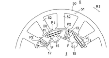
- FIG. 1 It is sectional drawing which shows the electric motor of Embodiment 1.
- FIG. It is sectional drawing which shows the rotor of Embodiment 1.
- FIG. It is sectional drawing which shows the rotor core and the permanent magnet of Embodiment 1.
- FIG. It is sectional drawing for demonstrating the width of the magnet magnetic pole and the width of the virtual magnetic pole of Embodiment 1.
- FIG. It is a schematic diagram which shows the magnet insertion hole and the slit in the rotor core of Embodiment 1.
- FIG. It is a magnetic flux diagram which shows the simulation result of the magnetic flux flow in the rotor of Embodiment 1.
- FIG. 1 It is a schematic diagram which shows the flow of the magnetic flux when the distance between a slit and the outer circumference of a rotor core is lengthened. It is a schematic diagram which shows the flow of the magnetic flux when the void part is not provided inside the magnet insertion hole in the radial direction. It is a schematic diagram for demonstrating the action of the void part of Embodiment 1. FIG. It is a schematic diagram for demonstrating the radial length of the slit and the void part of Embodiment 1. FIG. It is a schematic diagram which shows the example which made the length in the radial direction of a slit longer than the length in a radial direction of a gap part.
- FIG. It is a schematic diagram for demonstrating the flow of the magnetic flux in the example of FIG. It is a schematic diagram for demonstrating the arrangement of the caulking part of Embodiment 1.
- FIG. It is a magnetic flux diagram which shows the simulation result of the magnetic flux flow in the electric motor of Embodiment 1.
- FIG. It is sectional drawing which shows the rotor of Embodiment 2.
- FIG. It is a schematic diagram for demonstrating the arrangement of the magnet insertion hole, the slit, the gap part and the caulking part of Embodiment 2.
- It is a front view (A) which shows the air conditioner to which the motor of each embodiment is applied, and is the sectional view (B) which shows the outdoor unit.
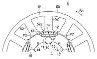
- FIG. 1 is a cross-sectional view showing the electric motor 100 of the first embodiment.
- the electric motor 100 is an inner rotor type electric motor including a rotatable rotor 1 and an annular stator 5 provided so as to surround the rotor 1.
- the electric motor 100 is also a permanent magnet embedded motor in which the permanent magnet 20 is embedded in the rotor 1.
- An air gap of, for example, 0.4 mm is provided between the stator 5 and the rotor 1.
- the rotation center axis of the rotor 1 will be the axis C1.
- the direction of the axis C1 is referred to as "axial direction”.
- the circumferential direction around the axis C1 (indicated by the arrow R1 in FIG. 1) is referred to as a "circumferential direction”.
- the radial direction centered on the axis C1 is referred to as a "diameter direction”.
- FIG. 1 is a cross-sectional view of a plane orthogonal to the axis C1 of the rotor 1.
- the stator 5 has a stator core 50 and a coil 55 wound around the stator core 50.
- the stator core 50 is formed by laminating a plurality of electromagnetic steel sheets in the axial direction and fixing them by caulking or the like.
- the thickness of the electromagnetic steel sheet is, for example, 0.1 mm to 0.7 mm.
- the stator core 50 has an annular yoke 51 centered on the axis C1 and a plurality of teeth 52 extending radially inward from the yoke 51.
- the teeth 52 are arranged at equal intervals in the circumferential direction.
- the number of teeth 52 is twelve here, but is not limited to twelve.
- a slot, which is a space for accommodating the coil 55, is formed between the adjacent teeth 52.
- the radial inner tip 52a of the teeth 52 is wider in the circumferential direction than the other parts of the teeth 52.
- the tip portion 52a of the teeth 52 faces the outer periphery of the rotor 1 via the air gap described above.
- An insulator 53 as an insulating portion is attached to the stator core 50.
- the insulator 53 is interposed between the stator core 50 and the coil 55 to insulate the stator core 50 and the coil 55.
- the insulator 53 is made of an insulating resin such as polybutylene terephthalate (PBT), for example.
- PBT polybutylene terephthalate
- the insulator 53 is formed by molding the resin integrally with the stator core 50 or by assembling a resin molded body molded as a separate component to the stator core 50.
- the coil 55 is wound around the teeth 52 via the insulator 53.
- the coil 55 is made of copper or aluminum.
- the coil 55 may be wound around each tooth 52 (concentrated winding), or may be wound across a plurality of teeth 52 (distributed winding).
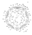
- FIG. 2 is a cross-sectional view showing the rotor 1.
- FIG. 3 is a diagram showing a rotor core 10 and a permanent magnet 20 of the rotor 1.
- the rotor 1 includes a shaft 25 which is a rotation shaft, a rotor core 10 provided on the radial outer side of the shaft 25, a plurality of permanent magnets 20 embedded in the rotor core 10, and a shaft 25 and a rotor core. It has a resin portion 30 provided between the 10 and the resin portion 30.
- the rotor core 10 is an annular member centered on the axis C1.
- the rotor core 10 has an outer circumference 16 and an inner circumference 17. Both the outer peripheral circumference 16 and the inner peripheral circumference 17 extend in the circumferential direction centered on the axis C1.
- the rotor core 10 is formed by laminating a plurality of electromagnetic steel sheets in the axial direction and fixing them by a caulking portion 14.
- the thickness of the electromagnetic steel sheet is, for example, 0.1 mm to 0.7 mm.
- the rotor core 10 has a plurality of magnet insertion holes 11.
- the magnet insertion holes 11 are arranged equidistantly in the circumferential direction and equidistant from the axis C1.
- the number of magnet insertion holes 11 is 5 here.
- the magnet insertion hole 11 is formed along the outer circumference of the rotor core 10.
- the magnet insertion hole 11 extends linearly in a direction orthogonal to a radial straight line (magnetic pole center line) passing through the center in the circumferential direction.
- the magnet insertion hole 11 is not limited to such a shape, and may be, for example, a V-shape.
- Flux barriers 12 which are holes, are formed on both sides of the magnet insertion hole 11 in the circumferential direction.
- the iron core portion between the flux barrier 12 and the outer peripheral 16 of the rotor core 10 is a thin-walled portion (also referred to as a bridge portion). In order to suppress the leakage flux between the adjacent magnetic poles, it is desirable that the thickness of the thin portion is the same as the thickness of the electromagnetic steel plate constituting the rotor core 10.
- a permanent magnet 20 is inserted into each magnet insertion hole 11.
- the permanent magnet 20 has a flat plate shape, and the cross-sectional shape orthogonal to the axial direction is rectangular.
- the permanent magnet 20 is composed of, for example, a rare earth magnet. More specifically, the permanent magnet 20 is composed of a neodymium sintered magnet containing Nd (neodymium) -Fe (iron) -B (boron).
- the five permanent magnets 20 have the same magnetic poles (for example, N poles) on the outer side in the radial direction.
- magnetic poles for example, S poles
- S poles opposite to the magnetic poles are formed between the permanent magnets 20 adjacent to each other in the circumferential direction.
- the rotor 1 is formed with five magnetic poles P1 composed of permanent magnets 20 and five virtual magnetic poles P2 composed of the rotor core 10. Such a configuration is called a sequential pole type. In the following, when the term "magnetic pole” is simply used, it is assumed that both the magnetic pole P1 and the virtual pole P2 are included. Here, the rotor 1 has 10 magnetic poles.
- Both the magnetic pole P1 and the virtual pole P2 have a polar center in the circumferential direction.
- the radial straight line passing through the polar center of the magnetic pole P1 is defined as the magnetic pole center line M1.
- the radial straight line passing through the pole center of the virtual magnetic pole P2 is defined as the magnetic pole center line M2.
- the outer circumference 16 of the rotor core 10 has a so-called flower circle shape in a cross section orthogonal to the axial direction. More specifically, the outer circumference 16 of the rotor core 10 has a shape in which the outer diameter is the maximum at the pole centers of the magnetic poles P1 and P2, the outer diameter is the smallest between the poles, and the arc shape is formed from the pole center to the poles. Have.
- the outer circumference 16 of the rotor core 10 is not limited to a flower circle shape, but may be a circular shape.
- the number of permanent magnets 20 can be halved as compared with the non-consequent pole type rotor having the same number of poles. Since the number of permanent magnets 20 is small, the manufacturing cost of the rotor 1 is reduced.
- the number of poles of the rotor 1 is 10, but the number of poles may be an even number of 4 or more.
- one permanent magnet 20 is arranged in one magnet insertion hole 11 here, two or more permanent magnets 20 may be arranged in one magnet insertion hole 11.
- the magnet magnetic pole P1 may be the S pole and the virtual magnetic pole P2 may be the N pole.
- a non-magnetic resin portion 30 is provided between the shaft 25 and the rotor core 10.
- the resin portion 30 connects the shaft 25 and the rotor core 10.
- the resin portion 30 is formed of, for example, a thermoplastic resin such as PBT.
- the resin portion 30 includes a plurality of annular inner cylinder portions 31 in contact with the outer periphery of the shaft 25, an annular outer cylinder portion 33 in contact with the inner circumference 17 of the rotor core 10, and a plurality of inner cylinder portions 31 and outer cylinder portions 33. It has a rib 32 and.
- a shaft 25 penetrates the inner cylinder portion 31 of the resin portion 30 in the axial direction.
- the ribs 32 are arranged at equal intervals in the circumferential direction, and extend radially outward from the inner cylinder portion 31.
- a cavity is formed between the ribs 32 adjacent to each other in the circumferential direction.
- the number of ribs 32 is half the number of poles, and the circumferential position of each rib 32 coincides with the pole center of the virtual magnetic pole P2. However, the number of ribs 32 is not limited to half the number of poles. Further, the circumferential position of the rib 32 may coincide with the polar center of the magnet magnetic pole P1.
- the rotor core 10 has at least one slit 13 in the virtual magnetic pole P2.
- two slits 13a arranged on both sides in the circumferential direction of the magnetic pole center line M2 and two slits 13b arranged on both sides in the circumferential direction of the two slits 13a are formed.
- Both the slits 13a and 13b extend in the radial direction, more specifically, in parallel with the magnetic pole center line M2. That is, the lengths of the slits 13a and 13b in the radial direction are longer than the width in the circumferential direction.
- the two slits 13a have the same shape as each other and are arranged equidistantly in the circumferential direction from the magnetic pole center line M2.
- the two slits 13b have the same shape as each other and are arranged equidistantly in the circumferential direction from the magnetic pole center line M2. That is, the four slits 13a and 13b are arranged symmetrically with respect to the magnetic pole center line M2.
- the radial length of the slit 13a is shorter than the radial length of the slit 13b.
- the circumferential width of the slit 13a is narrower than the circumferential width of the slit 13b.
- the radial outer end of the slit 13a is located radially outer than the radial outer end of the slit 13b.
- the virtual magnetic pole P2 has four slits 13a and 13b here, at least one slit 13 may be provided.
- slits 13 when it is not necessary to distinguish between the slits 13a and 13b, these are referred to as slits 13.
- the rotor core 10 has a gap 15 inside the magnet insertion hole 11 in the radial direction.
- the gap portion 15 is located on the magnetic pole center line M1 of the magnetic pole P1.
- the gap portion 15 has a circular shape on a plane orthogonal to the axial direction.
- the shape of the gap portion 15 is not limited to a circular shape, and may be a slit shape (see FIG. 21).
- a protruding portion 17a protruding inward in the radial direction is formed in the portion where the gap portion 15 is formed.
- the protruding portion 17a of the inner circumference 17 extends in an arc shape along the inner circumference of the gap portion 15.
- the protruding portion 17a functions as a rotation stopper for the rotor core 10 with respect to the resin portion 30.
- such a protruding portion 17a may not be formed on the inner circumference 17.
- the caulking portion 14 is for integrally fixing a plurality of electromagnetic steel sheets constituting the rotor core 10. It is desirable that the caulking portion 14 is formed on the magnetic pole center line M2 of the virtual magnetic pole P2 on the inner side in the radial direction with respect to the slit 13. However, the caulking portion 14 may be formed in another portion.
- the caulking portion 14 has a circular shape on a plane orthogonal to the axial direction. That is, the caulking portion 14 is a round caulking portion.
- the shape of the crimped portion 14 is not limited to a circular shape, and may be a rectangular shape. That is, the caulking portion 14 may be a V caulking portion (see FIG. 21).
- FIG. 4 is a cross-sectional view for explaining the circumferential width of the permanent magnet 20 and the circumferential width of the virtual magnetic pole P2.
- the circumferential width W1 of the permanent magnet 20 is, here, the circumferential length (distance from one end to the other end in the circumferential direction) of the radial outer surface of the permanent magnet 20.
- the circumferential width W2 of the virtual magnetic pole P2 is the distance from the flux barrier 12 located on one side of the virtual magnetic pole P2 in the circumferential direction to the flux barrier 12 located on the other side of the virtual magnetic pole P2 in the circumferential direction. Is.
- the circumferential width W2 of the virtual magnetic pole P2 is narrower than the circumferential width W1 of the permanent magnet 20. That is, W2 ⁇ W1 is established.
- widths W1 and W2 are not limited to the width in the circumferential direction. That is, the width W1 of the permanent magnet 20 may be the width in the direction orthogonal to the magnetic pole center line M1 (FIG. 3), and the width W2 of the virtual magnetic pole P2 may be the width in the direction orthogonal to the magnetic pole center line M2 (FIG. 3). May be. In this case as well, W2 ⁇ W1 holds.
- FIG. 5 is a schematic view showing the arrangement of the magnet insertion holes 11 and the slits 13 in the rotor core 10.
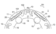
- the distance L1 from the magnet insertion hole 11 at the pole center to the outer circumference 16 of the rotor core 10 is shorter than the shortest distance L2 from the slit 13 to the outer circumference 16 of the rotor core 10.
- the shortest distance L2 is the distance from the slit 13a located on the outer peripheral 16 side of the slits 13a and 13b to the outer peripheral 16 of the rotor core 10.
- FIG. 6 is a magnetic flux diagram showing a simulation result of the flow of magnetic flux in the rotor 1.
- the magnetic flux emitted from the permanent magnet 20 of the magnetic pole P1 spreads symmetrically about the magnetic pole center line M1. This magnetic flux passes through the adjacent virtual magnetic poles P2 in the radial direction and returns to the permanent magnet 20 of the magnet magnetic poles P1.
- the magnetic flux emitted from the permanent magnet 20 passes through the virtual magnetic pole P2, if the width W2 of the virtual magnetic pole P2 is narrowed with respect to the width W1 of the permanent magnet 20, the magnetic flux is concentrated on the virtual magnetic pole P2, and the virtual magnetic pole is concentrated.
- the magnetic flux density at P2 becomes high.
- FIG. 7A is a graph showing the magnetic flux density distribution on the outer circumference of the rotor 1 obtained by actually measuring the magnetic flux density.
- the vertical axis is the magnetic flux density [mT]
- the horizontal axis is the circumferential position, that is, the angle [degree] about the axis C1.
- FIG. 7B is a schematic view showing the positions of the magnetic poles P1 and the virtual magnetic poles P2 corresponding to the magnetic flux density distribution of FIG. 7A.
- the magnetic flux density (that is, the surface magnetic flux density) on the outer circumference of the rotor 1 appears positive on the magnet magnetic pole P1 and negative on the virtual magnetic pole P2.
- the surface magnetic flux density zero-crosses at a position corresponding to the flux barrier 12.
- the surface magnetic flux density decreases at the respective pole centers of the magnetic pole P1 and the virtual pole P2 because the magnetic flux spreads symmetrically with respect to the magnetic pole center line (see FIG. 6).
- the magnet magnetic pole P1 has a permanent magnet 20, but the virtual magnetic pole P2 does not have a permanent magnet. Therefore, the surface magnetic flux density at the virtual magnetic pole P2 is lower than the surface magnetic flux density at the magnet magnetic pole P1.
- the low surface magnetic flux density of the virtual magnetic pole P2 with respect to the surface magnetic flux density of the magnet magnetic pole P1 causes vibration and noise of the rotor 1. This is because the magnetic attraction force acting between the virtual magnetic pole P2 and the teeth 52 is smaller than the magnetic attraction force acting between the magnet magnetic pole P1 and the teeth 52, so that the radial force applied to the rotor 1 is small. Is unbalanced, and a radial excitation force acts on the rotor 1.
- the magnetic magnetic pole P1 receives a circumferential force from the front teeth 52 and the rear teeth 52 in the rotation direction
- the virtual magnetic pole P2 receives the front teeth 52 and the rear teeth 52 in the rotation direction.
- the force in the circumferential direction received from is different. Therefore, the circumferential force applied to the rotor 1 becomes unbalanced, and torque ripple occurs in the rotor 1.
- the concentration of the magnetic flux on the virtual magnetic pole P2 is promoted.
- the surface magnetic flux density of is high. Therefore, the above-mentioned radial excitation force and torque ripple can be reduced, and vibration and noise can be reduced.
- the operation of the slit 13 will be described. As described above, even if the width W2 of the virtual magnetic pole P2 is narrower than the width W1 of the permanent magnet 20, the magnetic flux density at the virtual magnetic pole P2 does not reach the magnetic flux density at the magnet magnetic pole P1. , The magnetic flux passing through the virtual magnetic pole P2 tends to bend in the circumferential direction.
- FIG. 8 is a schematic view showing the flow of magnetic flux from the permanent magnet 20 of the magnet magnetic pole P1.
- the radial outside of the permanent magnet 20 is the north pole.
- the magnetic flux generated from the magnet magnetic pole P1 tends to travel outward in the radial direction as shown by the arrow F.
- FIG. 9 is a schematic view showing the flow of magnetic flux in the virtual magnetic pole P2 when the slit 13 is not provided in the virtual magnetic pole P2.
- the inside of the permanent magnet 20 in the radial direction is the north pole. Therefore, in the virtual magnetic pole P2, the magnetic flux flows from the inside in the radial direction to the inside and outside in the radial direction.
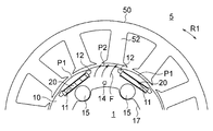
- FIG. 10 is a schematic view showing the arrangement of the slits 13 in the virtual magnetic pole P2 of the first embodiment.
- the rotor core 10 of the first embodiment has at least one slit 13 in the virtual magnetic pole P2. Further, the distance L1 from the magnet insertion hole 11 at the pole center to the outer circumference 16 of the rotor core 10 is shorter than the shortest distance L2 from the slit 13 to the outer circumference 16 of the rotor core 10.
- a core region 101 through which magnetic flux flows is formed between the magnet insertion hole 11 of the magnet magnetic pole P1 and the outer circumference 16 of the rotor core 10.
- a core region 102 through which magnetic flux flows is formed between the slit 13 of the virtual magnetic pole P2 and the outer circumference 16 of the rotor core 10.
- FIG. 11 is a schematic diagram for explaining the operation of the slit 13 in the virtual magnetic pole P2 of the first embodiment.
- the magnetic flux flowing through the virtual magnetic pole P2 tends to bend in the circumferential direction according to the position of the teeth 52 (FIG. 9) facing the virtual magnetic pole P2.
- the slit 13 is formed in the virtual magnetic pole P2
- the flow of magnetic flux at the virtual magnetic pole P2 can be rectified.
- the difference in surface magnetic flux density between the magnet magnetic pole P1 and the virtual magnetic pole P2 can be reduced, and the vibration and noise described above can be reduced.
- FIG. 12 is a cross-sectional view showing a non-consequential pole type rotor 1C.
- the rotor 1C has a rotor core 110 having a magnet insertion hole 111 and a permanent magnet 120 inserted into the magnet insertion hole 111.
- a shaft (not shown) is inserted into the center hole 117 of the rotor core 110.
- Adjacent permanent magnets 120 have magnetic pole surfaces that are opposite to each other on the outer side in the radial direction. That is, all the magnetic poles of the rotor 1C are formed by the magnet magnetic poles P.
- the distance L1 from the magnet insertion hole 111 to the outer circumference 116 of the rotor core 110 is constant at all magnetic poles.
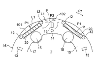
- FIG. 13 shows a configuration example in which the shortest distance from the slit 13 to the outer circumference 16 is the same as the distance L1 from the magnet insertion hole 11 at the pole center to the outer circumference 16 in the sequential pole type rotor.
- One slit 13 is shown for each virtual magnetic pole P2.
- the shortest distance from the slit 13 to the outer circumference 16 is the same as the distance L1 from the magnet insertion hole 11 to the outer circumference 16 at the polar center, so that the core region 102 on the outer side in the radial direction of the slit 13 Becomes wider. Therefore, the magnetic flux generated from the permanent magnet 20 tends to flow in the circumferential direction in the core region 102 of the virtual magnetic pole P2 as shown by the arrow F.
- the shortest distance L2 from the slit 13 to the outer circumference 16 of the rotor core 10 is shorter than the distance L1 from the magnet insertion hole 11 at the polar center to the outer circumference 16 of the rotor core 10. Therefore, as shown in FIG. 11, the core region 102 on the outer side in the radial direction of the slit 13 becomes narrow, and it becomes difficult for the magnetic flux to flow in the core region 102 in the circumferential direction. Therefore, the effect of bringing the magnetic flux flow in the virtual magnetic pole P2 closer to the radial direction, that is, the effect of rectifying the magnetic flux flow can be enhanced.
- the shortest distance L2 from the slit 13 to the outer circumference 16 is desirable in order to enhance the effect of rectifying the flow of magnetic flux, but it is difficult to make the distance L2 less than the thickness of the electromagnetic steel sheet in terms of processing. Therefore, the lower limit of the distance L2 is the thickness of the electromagnetic steel plate of the rotor core 10.
- FIG. 14 is a schematic view showing the flow of magnetic flux when the gap portion 15 is not formed inside the magnet insertion hole 11 in the radial direction.
- the magnetic flux emitted from the radial inside of the permanent magnet 20 of the magnet magnetic pole P1 flows to the teeth 52 through the two virtual magnetic poles P2 on both sides in the circumferential direction.
- a gap portion 15 is formed inside the magnet insertion hole 11 in the radial direction.
- the magnetic flux emitted from the radial inside of the permanent magnet 20 is evenly distributed to both sides in the circumferential direction by the gap portion 15.
- the magnetic flux generated from the permanent magnet 20 flows evenly in the circumferential direction regardless of the position of the teeth 52.
- the gap portion 15 is located on the magnetic pole center line M1.
- the distance T1 between the gap portion 15 and the magnet insertion hole 11 and the distance T2 between the gap portion 15 and the inner circumference 17 are eventually set.
- the diversion of the magnetic flux emitted from the radial inside of the permanent magnet 20 has been described, but when the radial inside of the permanent magnet 20 is the S pole, the magnetic flux flowing from both sides in the circumferential direction of the permanent magnet 20 is described. , The gap portion 15 evenly flows into the permanent magnet 20 in the circumferential direction. That is, the gap portion 15 can suppress the bias of the magnetic flux emitted from the permanent magnet 20 and the magnetic flux flowing into the permanent magnet 20.
- FIG. 16 is a schematic view for explaining the radial lengths of the slit 13 and the gap 15 of the rotor core 10.
- the slit 13 has a maximum radial length L3.
- the radial length of the slit 13b is set to the maximum length L3.
- the gap portion 15 has a maximum length L4 in the radial direction.
- the maximum length L4 of the gap portion 15 is the diameter of the gap portion 15.
- the maximum length L3 of the slit 13 is shorter than the maximum length L4 of the gap portion 15.
- FIG. 17 is a schematic view showing an example in which the maximum radial length L3 of the slit 13 is made longer than the maximum radial length L4 of the gap portion 15. As shown in FIG. 17, when the maximum radial length L3 of the slit 13 is made longer than the maximum radial length L4 of the gap portion 15, the slit 13 extends inward in the radial direction.
- the lengthening of the magnetic path in the rotor core 10 leads to an increase in iron loss, which contributes to a decrease in motor efficiency.
- the permanent magnet 20 passes through the virtual magnetic pole P2.
- the magnetic path toward the teeth 52 can be shortened, and an increase in iron loss can be suppressed.
- FIG. 19 is a schematic view for explaining the arrangement of the caulking portion 14 in the rotor core 10.
- the plurality of electrical steel sheets constituting the rotor core 10 are integrally fixed by the caulking portion 14.
- the caulking portion 14 is formed by pressing a caulking metal fitting against the surface of an electromagnetic steel plate. When stress is applied to electrical steel sheets, their magnetic properties change and iron loss increases. Therefore, if the caulked portion 14 is formed in the magnetic path, it causes an increase in iron loss.
- the caulking portion 14 is arranged inside the circle 18 (virtual circle) connecting the radial outer ends 15e of the gap portion 15.
- the magnetic flux generated from the permanent magnet 20 of the magnet magnetic pole P1 is diverted to both sides in the circumferential direction by the gap portion 15 and heads toward the virtual magnetic pole P2. Therefore, the amount of magnetic flux flowing is small in the region inside the circle 18 defined by the radial outer end portion 15e of the gap portion 15.
- the crimped portion 14 is arranged in the inner region of the circle 18, the magnetic flux passing through the crimped portion 14 is small. That is, it is possible to suppress an increase in iron loss due to the flow of magnetic flux through the crimped portion 14.
- the caulking portion 14 is formed inside the virtual magnetic pole P2 in the radial direction in FIG. 19, it may be formed at another position as long as it is inside the circle 18. Further, although the caulking portion 14 is a round caulking portion in FIG. 19, it may be a V caulking portion (FIG. 21) or a caulking portion having another shape.
- FIG. 20 is a magnetic flux diagram showing a simulation result of the flow of magnetic flux in the motor 100 of the first embodiment. From FIG. 20, it can be seen that the magnetic flux flowing through the virtual magnetic pole P2 tends to bend in the circumferential direction according to the position of the teeth 52, but is rectified by the slit 13 so that the flow of the magnetic flux approaches the radial direction.
- the magnetic flux is suppressed from flowing in the circumferential direction in the virtual magnetic pole P2. I understand.
- the magnetic flux emitted from the permanent magnet 20 is evenly divided in the circumferential direction by the gap portion 15, and the bias of the magnetic flux is suppressed. It can also be seen that the magnetic flux passing through the caulking portion 14 is small.
- a permanent magnet 20 having an N pole on the inside in the radial direction and a permanent magnet 20 having an S pole on the inside in the radial direction are adjacent to each other in the circumferential direction.
- the magnetic flux generated from the north pole of 20 flows to the south pole of the adjacent permanent magnet 20.
- a non-magnetic resin portion 30 is provided between the rotor core 10 and the shaft 25.
- the rotor 1 of the first embodiment has a rotor core 10 having a magnet insertion hole 11 and a permanent magnet 20 arranged in the magnet insertion hole 11, and the magnet magnetic pole P1 is formed by the permanent magnet 20.
- the virtual magnetic pole P2 is formed by a part of the rotor core 10.
- the circumferential width W2 of the virtual magnetic pole P2 is narrower than the circumferential width W1 of the permanent magnet 20, and at least one slit 13 is formed in the virtual magnetic pole P2.
- the magnetic flux can be concentrated on the virtual magnetic pole P2 and the magnetic flux density in the virtual magnetic pole P2 can be increased. Further, since the direction of the magnetic flux flowing through the virtual magnetic pole P2 can be brought closer to the radial direction by the one slit 13 provided in the virtual magnetic pole P2, the imbalance of the magnetic flux between the magnet magnetic pole P1 and the virtual magnetic pole P2 can be reduced. Can be done. As a result, vibration and noise can be reduced.
- the direction of the magnetic flux flowing through the virtual magnetic pole P2 is the diameter.
- the effect of approaching the direction is further enhanced, and the effect of reducing vibration and noise can be enhanced.
- the gap portion 15 is formed inside the magnet insertion hole 11 in the radial direction, the bias of the magnetic flux emitted from the permanent magnet 20 and the magnetic flux flowing into the permanent magnet 20 is suppressed, and the effect of reducing vibration and noise is further enhanced. Can be enhanced.
- the maximum radial length L3 of the slit 13 is shorter than the maximum radial length L4 of the gap portion 15, the magnetic path passing through the virtual magnetic pole P2 can be shortened, and an increase in iron loss can be suppressed. can do.
- the caulking portion 14 is formed inside the circle 18 passing through the radial outer end portion 15e of the gap portion 15, it is possible to suppress an increase in iron loss due to the magnetic flux passing through the caulking portion 14. can.
- the slit 13 extends in the radial direction, the effect of bringing the direction of the magnetic flux flowing through the virtual magnetic pole P2 closer to the radial direction can be enhanced.
- the plurality of slits 13a and 13b are formed symmetrically with respect to the magnetic pole center line M2, the effect of bringing the direction of the magnetic flux flowing through the virtual magnetic pole P2 closer to the radial direction can be further enhanced.
- the non-magnetic resin portion 30 is provided between the rotor core 10 and the shaft 25, the leakage flux from the rotor core 10 to the shaft 25, which is peculiar to the sequential pole type rotor, is effectively suppressed. be able to.
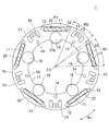
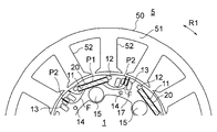
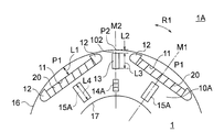
- FIG. 21 is a cross-sectional view showing a rotor core 10A and a permanent magnet 20 of the rotor 1A of the second embodiment.
- the rotor 1A of the second embodiment is different from the rotor 1 of the first embodiment in the shape and arrangement of the slit 13, the gap portion 15A and the caulking portion 14A of the rotor core 10A.
- each virtual magnetic pole P2 two slits 13 long in the radial direction are formed in each virtual magnetic pole P2.
- the two slits 13 have the same shape as each other, and are formed on both sides of the magnetic pole center line M2 in the circumferential direction at equal distances from the magnetic pole center line M2.
- the number of slits 13 of each virtual magnetic pole P2 is not limited to two, and may be one (FIG. 22) or three or more. Twice
- the gap portion 15A formed inside the magnet insertion hole 11 in the radial direction has a slit shape long in the radial direction. It is desirable that the gap portion 15A is formed on the magnetic pole center line M1.
- the caulking portion 14A is formed inside a circle 18 connecting the radial outer ends of the gap portion 15A.
- the caulking portion 14A is a V caulking portion.
- the V-caulking portion is formed by pressing a V-shaped caulking metal fitting against the surface of an electromagnetic steel plate. Therefore, the crimped portion 14A has a rectangular shape in a plane orthogonal to the axial direction.
- the caulking portion 14A is formed on the magnetic pole center line M2 of the virtual magnetic pole P2 so that the longitudinal direction coincides with the radial direction. This is because when the caulking portion 14A is arranged in this way, the magnetic flux passing through the caulking portion 14A is minimized (see FIG. 20), and the increase in iron loss can be effectively suppressed.
- the outer circumference 16 and the inner circumference 17 of the rotor core 10A are both circular around the axis C1.
- the outer circumference 16 may have a flower-round shape (FIG. 4) like the outer circumference 16 of the rotor core 10 of the first embodiment.
- the inner circumference 17 may have a protruding portion 17a (FIG. 4) like the inner circumference 17 of the rotor core 10 of the first embodiment.
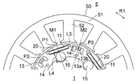
- FIG. 22 is a schematic view for explaining the arrangement of the slit 13, the gap portion 15A, and the caulking portion 14A of the second embodiment.
- the shortest distance L2 from the slit 13 to the outer circumference 16 of the rotor core 10A is shorter than the distance L1 from the magnet insertion hole 11 at the polar center to the outer circumference 16 of the rotor core 10A.
- the maximum radial length L3 of the slit 13 is shorter than the maximum radial length L4 of the gap portion 15A.
- the rotor 1A of the second embodiment is configured in the same manner as the rotor 1 of the first embodiment except for the shape and arrangement of the slit 13, the gap portion 15A and the caulking portion 14A.
- the slit 13 is formed in the virtual magnetic pole P2
- the direction of the magnetic flux flowing through the virtual magnetic pole P2 can be brought closer to the radial direction.
- the imbalance of magnetic flux between the magnetic pole P1 and the virtual pole P2 can be reduced, and vibration and noise can be reduced.
- the shortest distance L2 from the slit 13 to the outer circumference 16 of the rotor core 10A is shorter than the distance L1 from the magnet insertion hole 11 at the pole center to the outer circumference 16 of the rotor core 10A, it is difficult for the magnetic flux to flow in the circumferential direction on the virtual magnetic pole P2. Therefore, the effect of reducing vibration and noise can be further enhanced.
- the gap portion 15A is formed inside the magnet insertion hole 11 in the radial direction, the magnetic flux emitted from the permanent magnet 20 flows evenly in the circumferential direction, the imbalance of the magnetic flux is suppressed, and the effect of reducing vibration and noise is achieved. Can be further enhanced.
- the rotor 1 of the first embodiment may be combined with a part of the rotor 1A of the second embodiment.
- the slit-shaped gap portion 15A of the rotor 1A of the second embodiment may be provided.
- the caulking portion 14 (round caulking portion) of the rotor 1 of the first embodiment the caulking portion 14A (V caulking portion) of the rotor 1A of the second embodiment may be provided.
- a crimped portion 14B having a triangular in-plane shape orthogonal to the axial direction may be formed inside the circle 18 (FIG. 21) of the rotor core 10A.
- the arrangement of the caulking portion 14B shown in FIG. 23 is the same as that of the caulking portion 14A shown in FIGS. 21 and 22.
- FIG. 24A is a diagram showing a configuration of an air conditioner 500 to which the motor 100 of the first embodiment is applied.
- the air conditioner 500 includes an outdoor unit 501, an indoor unit 502, and a refrigerant pipe 503 connecting them.
- the outdoor unit 501 includes, for example, an outdoor blower 510 which is a propeller fan
- the indoor unit 502 includes, for example, an indoor blower 520 which is a cross-flow fan.
- the outdoor blower 510 has an impeller 505 and an electric motor 100A for driving the impeller 505.
- the indoor blower 520 has an impeller 521 and an electric motor 100B for driving the impeller 521.
- the motors 100A and 100B are composed of the motors 100 described in the first embodiment. Note that FIG. 24A also shows a compressor 504 that compresses the refrigerant.
- FIG. 24B is a cross-sectional view of the outdoor unit 501.
- the electric motor 100A is supported by a frame 509 arranged in the housing 508 of the outdoor unit 501.
- An impeller 505 is attached to the shaft 25 of the motor 100A via a hub 506.
- the impeller 505 rotates due to the rotation of the rotor 1 of the electric motor 100A, and air is blown to the heat exchanger (not shown).
- the heat released when the refrigerant compressed by the compressor 504 is condensed by the heat exchanger (condenser) is released to the outside by the blower of the outdoor blower 510.
- the impeller 521 is rotated by the rotation of the rotor 1 of the motor 100B to blow air into the room.
- the air conditioner 500 the air whose heat has been taken away when the refrigerant evaporates in the evaporator (not shown) is blown into the room by the blower of the indoor blower 520.
- the quietness of the blowers 510 and 520 can be improved. Thereby, the quietness of the air conditioner 500 can be improved.
- the motor 100 of the first embodiment is used for the motor 100A of the outdoor blower 510 and the motor 100B of the indoor blower 520, but if at least one of the motors 100A and 100B uses the motor 100 of the first embodiment. good. Further, instead of the electric motor 100 of the first embodiment, an electric motor provided with the rotor 1A (FIG. 21) of the second embodiment may be used.
- the motor 100 described in the first and second embodiments can be mounted on an electric device other than the blower of the air conditioner.
Landscapes
- Engineering & Computer Science (AREA)
- Power Engineering (AREA)
- Chemical & Material Sciences (AREA)
- Combustion & Propulsion (AREA)
- Mechanical Engineering (AREA)
- General Engineering & Computer Science (AREA)
- Permanent Field Magnets Of Synchronous Machinery (AREA)
- Iron Core Of Rotating Electric Machines (AREA)
- Connection Of Motors, Electrical Generators, Mechanical Devices, And The Like (AREA)
Priority Applications (4)
| Application Number | Priority Date | Filing Date | Title |
|---|---|---|---|
| JP2021577763A JP7204018B2 (ja) | 2020-02-12 | 2020-02-12 | ロータ、電動機、送風機および空気調和装置 |
| US17/789,299 US20220376569A1 (en) | 2020-02-12 | 2020-02-12 | Rotor, motor, fan, and air conditioner |
| CN202080093011.2A CN115039320A (zh) | 2020-02-12 | 2020-02-12 | 转子、电动机、送风机以及空调装置 |
| PCT/JP2020/005361 WO2021161421A1 (ja) | 2020-02-12 | 2020-02-12 | ロータ、電動機、送風機および空気調和装置 |
Applications Claiming Priority (1)
| Application Number | Priority Date | Filing Date | Title |
|---|---|---|---|
| PCT/JP2020/005361 WO2021161421A1 (ja) | 2020-02-12 | 2020-02-12 | ロータ、電動機、送風機および空気調和装置 |
Publications (1)
| Publication Number | Publication Date |
|---|---|
| WO2021161421A1 true WO2021161421A1 (ja) | 2021-08-19 |
Family
ID=77291458
Family Applications (1)
| Application Number | Title | Priority Date | Filing Date |
|---|---|---|---|
| PCT/JP2020/005361 Ceased WO2021161421A1 (ja) | 2020-02-12 | 2020-02-12 | ロータ、電動機、送風機および空気調和装置 |
Country Status (4)
| Country | Link |
|---|---|
| US (1) | US20220376569A1 (https=) |
| JP (1) | JP7204018B2 (https=) |
| CN (1) | CN115039320A (https=) |
| WO (1) | WO2021161421A1 (https=) |
Cited By (1)
| Publication number | Priority date | Publication date | Assignee | Title |
|---|---|---|---|---|
| US20240120787A1 (en) * | 2021-03-31 | 2024-04-11 | Mitsubishi Electric Corporation | Motor, compressor, and refrigeration cycle apparatus |
Families Citing this family (2)
| Publication number | Priority date | Publication date | Assignee | Title |
|---|---|---|---|---|
| WO2021171474A1 (ja) * | 2020-02-27 | 2021-09-02 | 三菱電機株式会社 | コンシクエントポール型ロータ、電動機、ファン、及び空気調和機 |
| JP7674977B2 (ja) * | 2021-09-28 | 2025-05-12 | 三菱電機株式会社 | 回転子及び回転電機、並びに回転子及び回転電機の製造方法 |
Citations (3)
| Publication number | Priority date | Publication date | Assignee | Title |
|---|---|---|---|---|
| WO2019026273A1 (ja) * | 2017-08-04 | 2019-02-07 | 三菱電機株式会社 | 回転子、電動機、送風機、空気調和装置および回転子の製造方法 |
| WO2019123962A1 (ja) * | 2017-12-21 | 2019-06-27 | 日本電産株式会社 | ロータおよびモータ |
| WO2020003341A1 (ja) * | 2018-06-25 | 2020-01-02 | 三菱電機株式会社 | ロータ、電動機、送風機および空気調和装置 |
Family Cites Families (48)
| Publication number | Priority date | Publication date | Assignee | Title |
|---|---|---|---|---|
| US5223759A (en) * | 1987-12-24 | 1993-06-29 | Seiko Epson Corporation | DC brushless motor with solid rotor having permanent magnet |
| US5508576A (en) * | 1990-07-12 | 1996-04-16 | Seiko Epson Corporation | Rotor for brushless electromotor |
| US5679995A (en) * | 1992-08-12 | 1997-10-21 | Seiko Epson Corporation | Permanent magnet rotor of brushless motor |
| JP3282427B2 (ja) * | 1994-04-13 | 2002-05-13 | トヨタ自動車株式会社 | 永久磁石モータ |
| TW538578B (en) * | 2000-09-13 | 2003-06-21 | Sanyo Electric Co | Synchronous motor with built-in type permanent magnet |
| DE10316831A1 (de) * | 2002-04-15 | 2003-11-27 | Denso Corp | Permanentmagnetrotor für eine rotierende elektrische Maschine mit Innenrotor und magnetsparender Rotor für einen Synchronmotor |
| ITBO20050437A1 (it) * | 2005-06-30 | 2007-01-01 | Spal Automotive Srl | Rotore per macchina elettrica |
| JP4815967B2 (ja) * | 2005-09-21 | 2011-11-16 | トヨタ自動車株式会社 | 永久磁石式回転電機 |
| JP4815204B2 (ja) * | 2005-12-01 | 2011-11-16 | アイチエレック株式会社 | 永久磁石回転機及び圧縮機 |
| US7705502B2 (en) * | 2006-04-14 | 2010-04-27 | Emerson Electric Co. | Interior magnet machine with non-perpendicular slots |
| US7791236B2 (en) * | 2007-08-16 | 2010-09-07 | Ford Global Technologies, Llc | Permanent magnet machine |
| JP2009131070A (ja) * | 2007-11-26 | 2009-06-11 | Denso Corp | 磁石式同期機 |
| US8242654B2 (en) * | 2009-05-20 | 2012-08-14 | Asmo Co., Ltd. | Rotor and motor |
| WO2011033397A2 (en) * | 2009-09-18 | 2011-03-24 | Brusa Elektronik Ag | Permanent magnet exited synchronous machine with embedded magnets |
| CN102035277B (zh) * | 2009-10-07 | 2014-08-20 | 阿斯莫有限公司 | 电动机 |
| US20120001509A1 (en) * | 2010-06-30 | 2012-01-05 | Asmo Co., Ltd. | Motor and rotor |
| US9178392B2 (en) * | 2010-08-27 | 2015-11-03 | Mitsubishi Electric Corporation | Rotor of permanent magnet embedded motor, compressor, and refrigeration and air conditioning apparatus |
| JP5353917B2 (ja) * | 2011-02-03 | 2013-11-27 | トヨタ自動車株式会社 | 回転電機用回転子 |
| EP2568578A3 (en) * | 2011-09-07 | 2017-12-06 | Samsung Electronics Co., Ltd. | Motor and washing machine having the same |
| CN103095010B (zh) * | 2011-10-28 | 2017-03-01 | 阿斯莫有限公司 | 转子及电动机 |
| JP6110151B2 (ja) * | 2013-02-07 | 2017-04-05 | 本田技研工業株式会社 | 回転電機のロータ |
| EP2966755B1 (en) * | 2013-03-08 | 2020-04-22 | Mitsubishi Electric Corporation | Multi-winding multi-phase ac motor and electric power-steering device |
| DE202013012708U1 (de) * | 2013-03-19 | 2018-09-19 | Ebm-Papst St. Georgen Gmbh & Co. Kg | Elektromotor mit Innenrotor und Außenstator |
| WO2015011747A1 (ja) * | 2013-07-22 | 2015-01-29 | 三菱電機株式会社 | 永久磁石型モータ、及び電動パワーステアリング装置 |
| WO2015045027A1 (ja) * | 2013-09-25 | 2015-04-02 | 三菱電機株式会社 | 永久磁石埋込型電動機、圧縮機及び冷凍空調装置 |
| JP5991545B2 (ja) * | 2013-11-15 | 2016-09-14 | 株式会社デンソー | 回転電機のロータ及びそのロータを備えた回転電機 |
| JP5872605B2 (ja) * | 2014-03-04 | 2016-03-01 | ダイキン工業株式会社 | ロータ |
| JP6226196B2 (ja) * | 2014-04-15 | 2017-11-08 | 株式会社デンソー | 回転電機のロータ |
| US10027193B2 (en) * | 2014-04-22 | 2018-07-17 | Mitsubishi Electric Corporation | Embedded permanent magnet-type electric motor, compressor, and refrigeration/air-conditioning device |
| WO2015162713A1 (ja) * | 2014-04-23 | 2015-10-29 | 三菱電機株式会社 | 永久磁石埋込型電動機、圧縮機、冷凍空調装置 |
| WO2016056065A1 (ja) * | 2014-10-07 | 2016-04-14 | 三菱電機株式会社 | 永久磁石埋込型電動機、圧縮機、および冷凍空調機 |
| JP6480789B2 (ja) * | 2015-04-13 | 2019-03-13 | 本田技研工業株式会社 | 回転電機のロータ |
| US10581286B2 (en) * | 2015-06-15 | 2020-03-03 | Mitsubishi Electric Corporation | Permanent-magnet-embedded electric motor and compressor |
| KR102008114B1 (ko) * | 2015-11-18 | 2019-08-06 | 미쓰비시덴키 가부시키가이샤 | 전동기 및 공기 조화기 |
| JP6298086B2 (ja) * | 2016-02-24 | 2018-03-20 | ファナック株式会社 | 電動機のロータ及びその製造方法 |
| US11031831B2 (en) * | 2016-04-21 | 2021-06-08 | Mitsubishi Electric Corporation | Electric motor and air conditioner |
| US10211690B2 (en) * | 2016-04-28 | 2019-02-19 | Faraday & Future Inc. | IPM machine with specialized rotor for automotive electric vehicles |
| JP6710276B2 (ja) * | 2016-05-31 | 2020-06-17 | 三菱電機株式会社 | 回転子、電動機、圧縮機、送風機、及び空気調和機 |
| EP3261220B1 (en) * | 2016-06-23 | 2020-08-12 | Volvo Car Corporation | Electric machine |
| US10211692B2 (en) * | 2016-08-11 | 2019-02-19 | Hiwin Mikrosystems Corp. | Permanent magnet motor |
| US10355537B2 (en) * | 2017-03-27 | 2019-07-16 | Ford Global Technologies, Llc | Method for adjusting magnetic permeability of electrical steel |
| WO2019026979A1 (ja) * | 2017-08-01 | 2019-02-07 | 株式会社デンソー | 回転電機、回転電機駆動システム、磁石、磁石の製造方法、着磁装置、及び磁石ユニット |
| CN108023421B (zh) * | 2017-12-21 | 2024-05-28 | 珠海格力电器股份有限公司 | 电机转子和永磁电机 |
| CN111903038B (zh) * | 2018-04-10 | 2023-11-28 | 三菱电机株式会社 | 电动机、压缩机及空气调节装置 |
| JP7053392B2 (ja) * | 2018-07-13 | 2022-04-12 | オークマ株式会社 | 同期電動機の回転子 |
| JP6755921B2 (ja) * | 2018-10-19 | 2020-09-16 | 本田技研工業株式会社 | ロータ |
| JP2020096410A (ja) * | 2018-12-10 | 2020-06-18 | 本田技研工業株式会社 | ロータ |
| DE102018132502A1 (de) * | 2018-12-17 | 2020-06-18 | Valeo Siemens Eautomotive Germany Gmbh | Rotorblech, Rotor und elektrische Maschine sowie Verfahren zur Herstellung eines Rotors |
-
2020
- 2020-02-12 US US17/789,299 patent/US20220376569A1/en not_active Abandoned
- 2020-02-12 JP JP2021577763A patent/JP7204018B2/ja active Active
- 2020-02-12 WO PCT/JP2020/005361 patent/WO2021161421A1/ja not_active Ceased
- 2020-02-12 CN CN202080093011.2A patent/CN115039320A/zh active Pending
Patent Citations (3)
| Publication number | Priority date | Publication date | Assignee | Title |
|---|---|---|---|---|
| WO2019026273A1 (ja) * | 2017-08-04 | 2019-02-07 | 三菱電機株式会社 | 回転子、電動機、送風機、空気調和装置および回転子の製造方法 |
| WO2019123962A1 (ja) * | 2017-12-21 | 2019-06-27 | 日本電産株式会社 | ロータおよびモータ |
| WO2020003341A1 (ja) * | 2018-06-25 | 2020-01-02 | 三菱電機株式会社 | ロータ、電動機、送風機および空気調和装置 |
Cited By (1)
| Publication number | Priority date | Publication date | Assignee | Title |
|---|---|---|---|---|
| US20240120787A1 (en) * | 2021-03-31 | 2024-04-11 | Mitsubishi Electric Corporation | Motor, compressor, and refrigeration cycle apparatus |
Also Published As
| Publication number | Publication date |
|---|---|
| US20220376569A1 (en) | 2022-11-24 |
| JP7204018B2 (ja) | 2023-01-13 |
| CN115039320A (zh) | 2022-09-09 |
| JPWO2021161421A1 (https=) | 2021-08-19 |
Similar Documents
| Publication | Publication Date | Title |
|---|---|---|
| US11552515B2 (en) | Rotor, motor, fan, and air conditioner | |
| US11190069B2 (en) | Consequent-pole-type rotor, electric motor, and air conditioner | |
| US11394260B2 (en) | Rotor, motor, fan, and air conditioning apparatus | |
| CN101981783A (zh) | 永久磁铁埋入式转子以及使用它的电动机及电气设备 | |
| JP7486629B2 (ja) | 回転子、電動機、送風機、空気調和装置、及び回転子の製造方法 | |
| WO2018189881A1 (ja) | ロータ、電動機および空気調和装置 | |
| WO2017203618A1 (ja) | 回転子、電動機、圧縮機、空気調和機、及び電動機の製造方法 | |
| JP7204018B2 (ja) | ロータ、電動機、送風機および空気調和装置 | |
| WO2018066084A1 (ja) | 電動機および空気調和装置 | |
| CN115088163A (zh) | 送风机及空气调节装置 | |
| JPWO2021161421A5 (https=) | ||
| WO2021117176A1 (ja) | ロータ、電動機、ファン、及び空気調和機 | |
| JPWO2021117176A5 (https=) | ||
| CN115104237A (zh) | 电动机、送风机以及空调装置 | |
| JP7559044B2 (ja) | 電動機、ファン、及び空気調和機 | |
| CN115136468B (zh) | 电动机、送风机及空调装置 | |
| JP2023067909A (ja) | 送風機および空気調和装置 | |
| JP7607790B2 (ja) | ロータ、電動機、送風機および空気調和装置 | |
| WO2023148949A1 (ja) | 電動機及び空気調和機 | |
| WO2023286117A1 (ja) | モータ、送風機および空気調和装置 | |
| WO2022085576A1 (ja) | ロータ及び該ロータを用いたモータ、並びに、電子機器 | |
| JP7381914B2 (ja) | 回転子、モータ、圧縮機および空気調和装置 | |
| WO2023148953A1 (ja) | ロータ、電動機、送風機、空気調和装置および電動機の製造方法 | |
| WO2025115126A1 (ja) | 電動機、送風機および空気調和装置 | |
| JPWO2023073757A5 (https=) |
Legal Events
| Date | Code | Title | Description |
|---|---|---|---|
| 121 | Ep: the epo has been informed by wipo that ep was designated in this application |
Ref document number: 20918548 Country of ref document: EP Kind code of ref document: A1 |
|
| ENP | Entry into the national phase |
Ref document number: 2021577763 Country of ref document: JP Kind code of ref document: A |
|
| NENP | Non-entry into the national phase |
Ref country code: DE |
|
| 122 | Ep: pct application non-entry in european phase |
Ref document number: 20918548 Country of ref document: EP Kind code of ref document: A1 |