WO2021157722A1 - ウェハーボート - Google Patents
ウェハーボート Download PDFInfo
- Publication number
- WO2021157722A1 WO2021157722A1 PCT/JP2021/004416 JP2021004416W WO2021157722A1 WO 2021157722 A1 WO2021157722 A1 WO 2021157722A1 JP 2021004416 W JP2021004416 W JP 2021004416W WO 2021157722 A1 WO2021157722 A1 WO 2021157722A1
- Authority
- WO
- WIPO (PCT)
- Prior art keywords
- wafer boat
- wafer
- boat according
- support column
- main component
- Prior art date
Links
- 239000000919 ceramic Substances 0.000 claims abstract description 25
- TWNQGVIAIRXVLR-UHFFFAOYSA-N oxo(oxoalumanyloxy)alumane Chemical compound O=[Al]O[Al]=O TWNQGVIAIRXVLR-UHFFFAOYSA-N 0.000 claims abstract description 16
- HBMJWWWQQXIZIP-UHFFFAOYSA-N silicon carbide Chemical compound [Si+]#[C-] HBMJWWWQQXIZIP-UHFFFAOYSA-N 0.000 claims abstract description 10
- 229910010271 silicon carbide Inorganic materials 0.000 claims abstract description 8
- 239000011148 porous material Substances 0.000 claims description 11
- 238000004140 cleaning Methods 0.000 claims description 8
- 238000010438 heat treatment Methods 0.000 claims description 7
- 230000005484 gravity Effects 0.000 claims description 4
- 235000012431 wafers Nutrition 0.000 abstract description 71
- 239000000306 component Substances 0.000 description 33
- 239000000843 powder Substances 0.000 description 14
- 238000000034 method Methods 0.000 description 12
- 238000010304 firing Methods 0.000 description 11
- 238000005498 polishing Methods 0.000 description 8
- 239000012298 atmosphere Substances 0.000 description 7
- 238000005259 measurement Methods 0.000 description 7
- 239000002245 particle Substances 0.000 description 7
- 230000002093 peripheral effect Effects 0.000 description 7
- 238000000227 grinding Methods 0.000 description 6
- 239000008187 granular material Substances 0.000 description 5
- 238000000465 moulding Methods 0.000 description 5
- 238000010298 pulverizing process Methods 0.000 description 5
- VTYYLEPIZMXCLO-UHFFFAOYSA-L Calcium carbonate Chemical compound [Ca+2].[O-]C([O-])=O VTYYLEPIZMXCLO-UHFFFAOYSA-L 0.000 description 4
- 238000004519 manufacturing process Methods 0.000 description 4
- 239000002002 slurry Substances 0.000 description 4
- XUIMIQQOPSSXEZ-UHFFFAOYSA-N Silicon Chemical compound [Si] XUIMIQQOPSSXEZ-UHFFFAOYSA-N 0.000 description 3
- 239000011230 binding agent Substances 0.000 description 3
- 238000005520 cutting process Methods 0.000 description 3
- 239000007788 liquid Substances 0.000 description 3
- 239000012779 reinforcing material Substances 0.000 description 3
- 229910052710 silicon Inorganic materials 0.000 description 3
- 239000010703 silicon Substances 0.000 description 3
- OYPRJOBELJOOCE-UHFFFAOYSA-N Calcium Chemical compound [Ca] OYPRJOBELJOOCE-UHFFFAOYSA-N 0.000 description 2
- FYYHWMGAXLPEAU-UHFFFAOYSA-N Magnesium Chemical compound [Mg] FYYHWMGAXLPEAU-UHFFFAOYSA-N 0.000 description 2
- VYPSYNLAJGMNEJ-UHFFFAOYSA-N Silicium dioxide Chemical compound O=[Si]=O VYPSYNLAJGMNEJ-UHFFFAOYSA-N 0.000 description 2
- 239000006061 abrasive grain Substances 0.000 description 2
- 229910052791 calcium Inorganic materials 0.000 description 2
- 239000011575 calcium Substances 0.000 description 2
- 229910000019 calcium carbonate Inorganic materials 0.000 description 2
- 230000007797 corrosion Effects 0.000 description 2
- 238000005260 corrosion Methods 0.000 description 2
- 229910003460 diamond Inorganic materials 0.000 description 2
- 239000010432 diamond Substances 0.000 description 2
- 239000002270 dispersing agent Substances 0.000 description 2
- 230000002706 hydrostatic effect Effects 0.000 description 2
- 238000009616 inductively coupled plasma Methods 0.000 description 2
- 229910052749 magnesium Inorganic materials 0.000 description 2
- 239000011777 magnesium Substances 0.000 description 2
- VTHJTEIRLNZDEV-UHFFFAOYSA-L magnesium dihydroxide Chemical compound [OH-].[OH-].[Mg+2] VTHJTEIRLNZDEV-UHFFFAOYSA-L 0.000 description 2
- 239000000347 magnesium hydroxide Substances 0.000 description 2
- 229910001862 magnesium hydroxide Inorganic materials 0.000 description 2
- 238000002156 mixing Methods 0.000 description 2
- 239000002243 precursor Substances 0.000 description 2
- 239000004065 semiconductor Substances 0.000 description 2
- 229910052814 silicon oxide Inorganic materials 0.000 description 2
- 239000002904 solvent Substances 0.000 description 2
- XLYOFNOQVPJJNP-UHFFFAOYSA-N water Substances O XLYOFNOQVPJJNP-UHFFFAOYSA-N 0.000 description 2
- 229910052580 B4C Inorganic materials 0.000 description 1
- OKTJSMMVPCPJKN-UHFFFAOYSA-N Carbon Chemical compound [C] OKTJSMMVPCPJKN-UHFFFAOYSA-N 0.000 description 1
- RYGMFSIKBFXOCR-UHFFFAOYSA-N Copper Chemical compound [Cu] RYGMFSIKBFXOCR-UHFFFAOYSA-N 0.000 description 1
- 229920003171 Poly (ethylene oxide) Polymers 0.000 description 1
- 239000002253 acid Substances 0.000 description 1
- NIXOWILDQLNWCW-UHFFFAOYSA-N acrylic acid group Chemical group C(C=C)(=O)O NIXOWILDQLNWCW-UHFFFAOYSA-N 0.000 description 1
- 230000001154 acute effect Effects 0.000 description 1
- 239000000853 adhesive Substances 0.000 description 1
- 230000001070 adhesive effect Effects 0.000 description 1
- 239000003513 alkali Substances 0.000 description 1
- 229910003481 amorphous carbon Inorganic materials 0.000 description 1
- 238000004458 analytical method Methods 0.000 description 1
- 239000012300 argon atmosphere Substances 0.000 description 1
- INAHAJYZKVIDIZ-UHFFFAOYSA-N boron carbide Chemical compound B12B3B4C32B41 INAHAJYZKVIDIZ-UHFFFAOYSA-N 0.000 description 1
- 229910052802 copper Inorganic materials 0.000 description 1
- 239000010949 copper Substances 0.000 description 1
- 238000009792 diffusion process Methods 0.000 description 1
- 239000006185 dispersion Substances 0.000 description 1
- 239000002019 doping agent Substances 0.000 description 1
- 238000001035 drying Methods 0.000 description 1
- 239000000839 emulsion Substances 0.000 description 1
- 239000011521 glass Substances 0.000 description 1
- 239000012535 impurity Substances 0.000 description 1
- 239000011261 inert gas Substances 0.000 description 1
- 239000012299 nitrogen atmosphere Substances 0.000 description 1
- 239000005011 phenolic resin Substances 0.000 description 1
- 229920001223 polyethylene glycol Polymers 0.000 description 1
- 229920002451 polyvinyl alcohol Polymers 0.000 description 1
- 235000019422 polyvinyl alcohol Nutrition 0.000 description 1
- 230000035939 shock Effects 0.000 description 1
- 238000005245 sintering Methods 0.000 description 1
- 230000003746 surface roughness Effects 0.000 description 1
- 239000005028 tinplate Substances 0.000 description 1
- 239000011800 void material Substances 0.000 description 1
- 239000013585 weight reducing agent Substances 0.000 description 1
Images


Classifications
-
- H—ELECTRICITY
- H01—ELECTRIC ELEMENTS
- H01L—SEMICONDUCTOR DEVICES NOT COVERED BY CLASS H10
- H01L21/00—Processes or apparatus adapted for the manufacture or treatment of semiconductor or solid state devices or of parts thereof
- H01L21/67—Apparatus specially adapted for handling semiconductor or electric solid state devices during manufacture or treatment thereof; Apparatus specially adapted for handling wafers during manufacture or treatment of semiconductor or electric solid state devices or components ; Apparatus not specifically provided for elsewhere
- H01L21/673—Apparatus specially adapted for handling semiconductor or electric solid state devices during manufacture or treatment thereof; Apparatus specially adapted for handling wafers during manufacture or treatment of semiconductor or electric solid state devices or components ; Apparatus not specifically provided for elsewhere using specially adapted carriers or holders; Fixing the workpieces on such carriers or holders
- H01L21/67313—Horizontal boat type carrier whereby the substrates are vertically supported, e.g. comprising rod-shaped elements
-
- C—CHEMISTRY; METALLURGY
- C04—CEMENTS; CONCRETE; ARTIFICIAL STONE; CERAMICS; REFRACTORIES
- C04B—LIME, MAGNESIA; SLAG; CEMENTS; COMPOSITIONS THEREOF, e.g. MORTARS, CONCRETE OR LIKE BUILDING MATERIALS; ARTIFICIAL STONE; CERAMICS; REFRACTORIES; TREATMENT OF NATURAL STONE
- C04B35/00—Shaped ceramic products characterised by their composition; Ceramics compositions; Processing powders of inorganic compounds preparatory to the manufacturing of ceramic products
- C04B35/01—Shaped ceramic products characterised by their composition; Ceramics compositions; Processing powders of inorganic compounds preparatory to the manufacturing of ceramic products based on oxide ceramics
- C04B35/10—Shaped ceramic products characterised by their composition; Ceramics compositions; Processing powders of inorganic compounds preparatory to the manufacturing of ceramic products based on oxide ceramics based on aluminium oxide
- C04B35/111—Fine ceramics
-
- C—CHEMISTRY; METALLURGY
- C04—CEMENTS; CONCRETE; ARTIFICIAL STONE; CERAMICS; REFRACTORIES
- C04B—LIME, MAGNESIA; SLAG; CEMENTS; COMPOSITIONS THEREOF, e.g. MORTARS, CONCRETE OR LIKE BUILDING MATERIALS; ARTIFICIAL STONE; CERAMICS; REFRACTORIES; TREATMENT OF NATURAL STONE
- C04B35/00—Shaped ceramic products characterised by their composition; Ceramics compositions; Processing powders of inorganic compounds preparatory to the manufacturing of ceramic products
- C04B35/515—Shaped ceramic products characterised by their composition; Ceramics compositions; Processing powders of inorganic compounds preparatory to the manufacturing of ceramic products based on non-oxide ceramics
- C04B35/56—Shaped ceramic products characterised by their composition; Ceramics compositions; Processing powders of inorganic compounds preparatory to the manufacturing of ceramic products based on non-oxide ceramics based on carbides or oxycarbides
- C04B35/565—Shaped ceramic products characterised by their composition; Ceramics compositions; Processing powders of inorganic compounds preparatory to the manufacturing of ceramic products based on non-oxide ceramics based on carbides or oxycarbides based on silicon carbide
-
- C—CHEMISTRY; METALLURGY
- C04—CEMENTS; CONCRETE; ARTIFICIAL STONE; CERAMICS; REFRACTORIES
- C04B—LIME, MAGNESIA; SLAG; CEMENTS; COMPOSITIONS THEREOF, e.g. MORTARS, CONCRETE OR LIKE BUILDING MATERIALS; ARTIFICIAL STONE; CERAMICS; REFRACTORIES; TREATMENT OF NATURAL STONE
- C04B35/00—Shaped ceramic products characterised by their composition; Ceramics compositions; Processing powders of inorganic compounds preparatory to the manufacturing of ceramic products
- C04B35/622—Forming processes; Processing powders of inorganic compounds preparatory to the manufacturing of ceramic products
- C04B35/626—Preparing or treating the powders individually or as batches ; preparing or treating macroscopic reinforcing agents for ceramic products, e.g. fibres; mechanical aspects section B
- C04B35/62605—Treating the starting powders individually or as mixtures
- C04B35/62645—Thermal treatment of powders or mixtures thereof other than sintering
- C04B35/62655—Drying, e.g. freeze-drying, spray-drying, microwave or supercritical drying
-
- C—CHEMISTRY; METALLURGY
- C04—CEMENTS; CONCRETE; ARTIFICIAL STONE; CERAMICS; REFRACTORIES
- C04B—LIME, MAGNESIA; SLAG; CEMENTS; COMPOSITIONS THEREOF, e.g. MORTARS, CONCRETE OR LIKE BUILDING MATERIALS; ARTIFICIAL STONE; CERAMICS; REFRACTORIES; TREATMENT OF NATURAL STONE
- C04B35/00—Shaped ceramic products characterised by their composition; Ceramics compositions; Processing powders of inorganic compounds preparatory to the manufacturing of ceramic products
- C04B35/622—Forming processes; Processing powders of inorganic compounds preparatory to the manufacturing of ceramic products
- C04B35/626—Preparing or treating the powders individually or as batches ; preparing or treating macroscopic reinforcing agents for ceramic products, e.g. fibres; mechanical aspects section B
- C04B35/62605—Treating the starting powders individually or as mixtures
- C04B35/62695—Granulation or pelletising
-
- C—CHEMISTRY; METALLURGY
- C04—CEMENTS; CONCRETE; ARTIFICIAL STONE; CERAMICS; REFRACTORIES
- C04B—LIME, MAGNESIA; SLAG; CEMENTS; COMPOSITIONS THEREOF, e.g. MORTARS, CONCRETE OR LIKE BUILDING MATERIALS; ARTIFICIAL STONE; CERAMICS; REFRACTORIES; TREATMENT OF NATURAL STONE
- C04B35/00—Shaped ceramic products characterised by their composition; Ceramics compositions; Processing powders of inorganic compounds preparatory to the manufacturing of ceramic products
- C04B35/622—Forming processes; Processing powders of inorganic compounds preparatory to the manufacturing of ceramic products
- C04B35/626—Preparing or treating the powders individually or as batches ; preparing or treating macroscopic reinforcing agents for ceramic products, e.g. fibres; mechanical aspects section B
- C04B35/63—Preparing or treating the powders individually or as batches ; preparing or treating macroscopic reinforcing agents for ceramic products, e.g. fibres; mechanical aspects section B using additives specially adapted for forming the products, e.g.. binder binders
- C04B35/632—Organic additives
- C04B35/634—Polymers
- C04B35/63404—Polymers obtained by reactions only involving carbon-to-carbon unsaturated bonds
- C04B35/63416—Polyvinylalcohols [PVA]; Polyvinylacetates
-
- C—CHEMISTRY; METALLURGY
- C04—CEMENTS; CONCRETE; ARTIFICIAL STONE; CERAMICS; REFRACTORIES
- C04B—LIME, MAGNESIA; SLAG; CEMENTS; COMPOSITIONS THEREOF, e.g. MORTARS, CONCRETE OR LIKE BUILDING MATERIALS; ARTIFICIAL STONE; CERAMICS; REFRACTORIES; TREATMENT OF NATURAL STONE
- C04B35/00—Shaped ceramic products characterised by their composition; Ceramics compositions; Processing powders of inorganic compounds preparatory to the manufacturing of ceramic products
- C04B35/622—Forming processes; Processing powders of inorganic compounds preparatory to the manufacturing of ceramic products
- C04B35/626—Preparing or treating the powders individually or as batches ; preparing or treating macroscopic reinforcing agents for ceramic products, e.g. fibres; mechanical aspects section B
- C04B35/63—Preparing or treating the powders individually or as batches ; preparing or treating macroscopic reinforcing agents for ceramic products, e.g. fibres; mechanical aspects section B using additives specially adapted for forming the products, e.g.. binder binders
- C04B35/632—Organic additives
- C04B35/634—Polymers
- C04B35/63404—Polymers obtained by reactions only involving carbon-to-carbon unsaturated bonds
- C04B35/63424—Polyacrylates; Polymethacrylates
-
- C—CHEMISTRY; METALLURGY
- C04—CEMENTS; CONCRETE; ARTIFICIAL STONE; CERAMICS; REFRACTORIES
- C04B—LIME, MAGNESIA; SLAG; CEMENTS; COMPOSITIONS THEREOF, e.g. MORTARS, CONCRETE OR LIKE BUILDING MATERIALS; ARTIFICIAL STONE; CERAMICS; REFRACTORIES; TREATMENT OF NATURAL STONE
- C04B35/00—Shaped ceramic products characterised by their composition; Ceramics compositions; Processing powders of inorganic compounds preparatory to the manufacturing of ceramic products
- C04B35/622—Forming processes; Processing powders of inorganic compounds preparatory to the manufacturing of ceramic products
- C04B35/626—Preparing or treating the powders individually or as batches ; preparing or treating macroscopic reinforcing agents for ceramic products, e.g. fibres; mechanical aspects section B
- C04B35/63—Preparing or treating the powders individually or as batches ; preparing or treating macroscopic reinforcing agents for ceramic products, e.g. fibres; mechanical aspects section B using additives specially adapted for forming the products, e.g.. binder binders
- C04B35/632—Organic additives
- C04B35/634—Polymers
- C04B35/63448—Polymers obtained otherwise than by reactions only involving carbon-to-carbon unsaturated bonds
- C04B35/63472—Condensation polymers of aldehydes or ketones
- C04B35/63476—Phenol-formaldehyde condensation polymers
-
- C—CHEMISTRY; METALLURGY
- C04—CEMENTS; CONCRETE; ARTIFICIAL STONE; CERAMICS; REFRACTORIES
- C04B—LIME, MAGNESIA; SLAG; CEMENTS; COMPOSITIONS THEREOF, e.g. MORTARS, CONCRETE OR LIKE BUILDING MATERIALS; ARTIFICIAL STONE; CERAMICS; REFRACTORIES; TREATMENT OF NATURAL STONE
- C04B35/00—Shaped ceramic products characterised by their composition; Ceramics compositions; Processing powders of inorganic compounds preparatory to the manufacturing of ceramic products
- C04B35/622—Forming processes; Processing powders of inorganic compounds preparatory to the manufacturing of ceramic products
- C04B35/626—Preparing or treating the powders individually or as batches ; preparing or treating macroscopic reinforcing agents for ceramic products, e.g. fibres; mechanical aspects section B
- C04B35/63—Preparing or treating the powders individually or as batches ; preparing or treating macroscopic reinforcing agents for ceramic products, e.g. fibres; mechanical aspects section B using additives specially adapted for forming the products, e.g.. binder binders
- C04B35/632—Organic additives
- C04B35/634—Polymers
- C04B35/63448—Polymers obtained otherwise than by reactions only involving carbon-to-carbon unsaturated bonds
- C04B35/63488—Polyethers, e.g. alkylphenol polyglycolether, polyethylene glycol [PEG], polyethylene oxide [PEO]
-
- H—ELECTRICITY
- H01—ELECTRIC ELEMENTS
- H01L—SEMICONDUCTOR DEVICES NOT COVERED BY CLASS H10
- H01L21/00—Processes or apparatus adapted for the manufacture or treatment of semiconductor or solid state devices or of parts thereof
- H01L21/67—Apparatus specially adapted for handling semiconductor or electric solid state devices during manufacture or treatment thereof; Apparatus specially adapted for handling wafers during manufacture or treatment of semiconductor or electric solid state devices or components ; Apparatus not specifically provided for elsewhere
- H01L21/673—Apparatus specially adapted for handling semiconductor or electric solid state devices during manufacture or treatment thereof; Apparatus specially adapted for handling wafers during manufacture or treatment of semiconductor or electric solid state devices or components ; Apparatus not specifically provided for elsewhere using specially adapted carriers or holders; Fixing the workpieces on such carriers or holders
- H01L21/67313—Horizontal boat type carrier whereby the substrates are vertically supported, e.g. comprising rod-shaped elements
- H01L21/67316—Horizontal boat type carrier whereby the substrates are vertically supported, e.g. comprising rod-shaped elements characterized by a material, a roughness, a coating or the like
-
- C—CHEMISTRY; METALLURGY
- C04—CEMENTS; CONCRETE; ARTIFICIAL STONE; CERAMICS; REFRACTORIES
- C04B—LIME, MAGNESIA; SLAG; CEMENTS; COMPOSITIONS THEREOF, e.g. MORTARS, CONCRETE OR LIKE BUILDING MATERIALS; ARTIFICIAL STONE; CERAMICS; REFRACTORIES; TREATMENT OF NATURAL STONE
- C04B2235/00—Aspects relating to ceramic starting mixtures or sintered ceramic products
- C04B2235/02—Composition of constituents of the starting material or of secondary phases of the final product
- C04B2235/30—Constituents and secondary phases not being of a fibrous nature
- C04B2235/32—Metal oxides, mixed metal oxides, or oxide-forming salts thereof, e.g. carbonates, nitrates, (oxy)hydroxides, chlorides
- C04B2235/3205—Alkaline earth oxides or oxide forming salts thereof, e.g. beryllium oxide
- C04B2235/3206—Magnesium oxides or oxide-forming salts thereof
-
- C—CHEMISTRY; METALLURGY
- C04—CEMENTS; CONCRETE; ARTIFICIAL STONE; CERAMICS; REFRACTORIES
- C04B—LIME, MAGNESIA; SLAG; CEMENTS; COMPOSITIONS THEREOF, e.g. MORTARS, CONCRETE OR LIKE BUILDING MATERIALS; ARTIFICIAL STONE; CERAMICS; REFRACTORIES; TREATMENT OF NATURAL STONE
- C04B2235/00—Aspects relating to ceramic starting mixtures or sintered ceramic products
- C04B2235/02—Composition of constituents of the starting material or of secondary phases of the final product
- C04B2235/30—Constituents and secondary phases not being of a fibrous nature
- C04B2235/32—Metal oxides, mixed metal oxides, or oxide-forming salts thereof, e.g. carbonates, nitrates, (oxy)hydroxides, chlorides
- C04B2235/3205—Alkaline earth oxides or oxide forming salts thereof, e.g. beryllium oxide
- C04B2235/3208—Calcium oxide or oxide-forming salts thereof, e.g. lime
-
- C—CHEMISTRY; METALLURGY
- C04—CEMENTS; CONCRETE; ARTIFICIAL STONE; CERAMICS; REFRACTORIES
- C04B—LIME, MAGNESIA; SLAG; CEMENTS; COMPOSITIONS THEREOF, e.g. MORTARS, CONCRETE OR LIKE BUILDING MATERIALS; ARTIFICIAL STONE; CERAMICS; REFRACTORIES; TREATMENT OF NATURAL STONE
- C04B2235/00—Aspects relating to ceramic starting mixtures or sintered ceramic products
- C04B2235/02—Composition of constituents of the starting material or of secondary phases of the final product
- C04B2235/30—Constituents and secondary phases not being of a fibrous nature
- C04B2235/34—Non-metal oxides, non-metal mixed oxides, or salts thereof that form the non-metal oxides upon heating, e.g. carbonates, nitrates, (oxy)hydroxides, chlorides
- C04B2235/3418—Silicon oxide, silicic acids or oxide forming salts thereof, e.g. silica sol, fused silica, silica fume, cristobalite, quartz or flint
-
- C—CHEMISTRY; METALLURGY
- C04—CEMENTS; CONCRETE; ARTIFICIAL STONE; CERAMICS; REFRACTORIES
- C04B—LIME, MAGNESIA; SLAG; CEMENTS; COMPOSITIONS THEREOF, e.g. MORTARS, CONCRETE OR LIKE BUILDING MATERIALS; ARTIFICIAL STONE; CERAMICS; REFRACTORIES; TREATMENT OF NATURAL STONE
- C04B2235/00—Aspects relating to ceramic starting mixtures or sintered ceramic products
- C04B2235/02—Composition of constituents of the starting material or of secondary phases of the final product
- C04B2235/30—Constituents and secondary phases not being of a fibrous nature
- C04B2235/38—Non-oxide ceramic constituents or additives
- C04B2235/3817—Carbides
- C04B2235/3821—Boron carbides
-
- C—CHEMISTRY; METALLURGY
- C04—CEMENTS; CONCRETE; ARTIFICIAL STONE; CERAMICS; REFRACTORIES
- C04B—LIME, MAGNESIA; SLAG; CEMENTS; COMPOSITIONS THEREOF, e.g. MORTARS, CONCRETE OR LIKE BUILDING MATERIALS; ARTIFICIAL STONE; CERAMICS; REFRACTORIES; TREATMENT OF NATURAL STONE
- C04B2235/00—Aspects relating to ceramic starting mixtures or sintered ceramic products
- C04B2235/02—Composition of constituents of the starting material or of secondary phases of the final product
- C04B2235/30—Constituents and secondary phases not being of a fibrous nature
- C04B2235/42—Non metallic elements added as constituents or additives, e.g. sulfur, phosphor, selenium or tellurium
- C04B2235/422—Carbon
-
- C—CHEMISTRY; METALLURGY
- C04—CEMENTS; CONCRETE; ARTIFICIAL STONE; CERAMICS; REFRACTORIES
- C04B—LIME, MAGNESIA; SLAG; CEMENTS; COMPOSITIONS THEREOF, e.g. MORTARS, CONCRETE OR LIKE BUILDING MATERIALS; ARTIFICIAL STONE; CERAMICS; REFRACTORIES; TREATMENT OF NATURAL STONE
- C04B2235/00—Aspects relating to ceramic starting mixtures or sintered ceramic products
- C04B2235/02—Composition of constituents of the starting material or of secondary phases of the final product
- C04B2235/30—Constituents and secondary phases not being of a fibrous nature
- C04B2235/48—Organic compounds becoming part of a ceramic after heat treatment, e.g. carbonising phenol resins
-
- C—CHEMISTRY; METALLURGY
- C04—CEMENTS; CONCRETE; ARTIFICIAL STONE; CERAMICS; REFRACTORIES
- C04B—LIME, MAGNESIA; SLAG; CEMENTS; COMPOSITIONS THEREOF, e.g. MORTARS, CONCRETE OR LIKE BUILDING MATERIALS; ARTIFICIAL STONE; CERAMICS; REFRACTORIES; TREATMENT OF NATURAL STONE
- C04B2235/00—Aspects relating to ceramic starting mixtures or sintered ceramic products
- C04B2235/02—Composition of constituents of the starting material or of secondary phases of the final product
- C04B2235/50—Constituents or additives of the starting mixture chosen for their shape or used because of their shape or their physical appearance
- C04B2235/54—Particle size related information
- C04B2235/5418—Particle size related information expressed by the size of the particles or aggregates thereof
- C04B2235/5436—Particle size related information expressed by the size of the particles or aggregates thereof micrometer sized, i.e. from 1 to 100 micron
-
- C—CHEMISTRY; METALLURGY
- C04—CEMENTS; CONCRETE; ARTIFICIAL STONE; CERAMICS; REFRACTORIES
- C04B—LIME, MAGNESIA; SLAG; CEMENTS; COMPOSITIONS THEREOF, e.g. MORTARS, CONCRETE OR LIKE BUILDING MATERIALS; ARTIFICIAL STONE; CERAMICS; REFRACTORIES; TREATMENT OF NATURAL STONE
- C04B2235/00—Aspects relating to ceramic starting mixtures or sintered ceramic products
- C04B2235/02—Composition of constituents of the starting material or of secondary phases of the final product
- C04B2235/50—Constituents or additives of the starting mixture chosen for their shape or used because of their shape or their physical appearance
- C04B2235/54—Particle size related information
- C04B2235/5463—Particle size distributions
- C04B2235/5472—Bimodal, multi-modal or multi-fraction
-
- C—CHEMISTRY; METALLURGY
- C04—CEMENTS; CONCRETE; ARTIFICIAL STONE; CERAMICS; REFRACTORIES
- C04B—LIME, MAGNESIA; SLAG; CEMENTS; COMPOSITIONS THEREOF, e.g. MORTARS, CONCRETE OR LIKE BUILDING MATERIALS; ARTIFICIAL STONE; CERAMICS; REFRACTORIES; TREATMENT OF NATURAL STONE
- C04B2235/00—Aspects relating to ceramic starting mixtures or sintered ceramic products
- C04B2235/65—Aspects relating to heat treatments of ceramic bodies such as green ceramics or pre-sintered ceramics, e.g. burning, sintering or melting processes
- C04B2235/656—Aspects relating to heat treatments of ceramic bodies such as green ceramics or pre-sintered ceramics, e.g. burning, sintering or melting processes characterised by specific heating conditions during heat treatment
- C04B2235/6567—Treatment time
-
- C—CHEMISTRY; METALLURGY
- C04—CEMENTS; CONCRETE; ARTIFICIAL STONE; CERAMICS; REFRACTORIES
- C04B—LIME, MAGNESIA; SLAG; CEMENTS; COMPOSITIONS THEREOF, e.g. MORTARS, CONCRETE OR LIKE BUILDING MATERIALS; ARTIFICIAL STONE; CERAMICS; REFRACTORIES; TREATMENT OF NATURAL STONE
- C04B2235/00—Aspects relating to ceramic starting mixtures or sintered ceramic products
- C04B2235/65—Aspects relating to heat treatments of ceramic bodies such as green ceramics or pre-sintered ceramics, e.g. burning, sintering or melting processes
- C04B2235/658—Atmosphere during thermal treatment
- C04B2235/6581—Total pressure below 1 atmosphere, e.g. vacuum
-
- C—CHEMISTRY; METALLURGY
- C04—CEMENTS; CONCRETE; ARTIFICIAL STONE; CERAMICS; REFRACTORIES
- C04B—LIME, MAGNESIA; SLAG; CEMENTS; COMPOSITIONS THEREOF, e.g. MORTARS, CONCRETE OR LIKE BUILDING MATERIALS; ARTIFICIAL STONE; CERAMICS; REFRACTORIES; TREATMENT OF NATURAL STONE
- C04B2235/00—Aspects relating to ceramic starting mixtures or sintered ceramic products
- C04B2235/70—Aspects relating to sintered or melt-casted ceramic products
- C04B2235/94—Products characterised by their shape
- C04B2235/945—Products containing grooves, cuts, recesses or protusions
-
- C—CHEMISTRY; METALLURGY
- C04—CEMENTS; CONCRETE; ARTIFICIAL STONE; CERAMICS; REFRACTORIES
- C04B—LIME, MAGNESIA; SLAG; CEMENTS; COMPOSITIONS THEREOF, e.g. MORTARS, CONCRETE OR LIKE BUILDING MATERIALS; ARTIFICIAL STONE; CERAMICS; REFRACTORIES; TREATMENT OF NATURAL STONE
- C04B2235/00—Aspects relating to ceramic starting mixtures or sintered ceramic products
- C04B2235/70—Aspects relating to sintered or melt-casted ceramic products
- C04B2235/96—Properties of ceramic products, e.g. mechanical properties such as strength, toughness, wear resistance
- C04B2235/963—Surface properties, e.g. surface roughness
Definitions
- This disclosure relates to wafer boats.
- wafers are used to form an oxide film on the surface of a semiconductor wafer (hereinafter, may be simply referred to as “wafer”) or to diffuse a dopant. It includes a step of heat treatment at a high temperature of about ° C. In such a heat treatment step, a wafer boat as described in Patent Document 1 is used in order to place a plurality of wafers in the horizontal direction at predetermined intervals.
- the wafer boat according to the present disclosure includes a plurality of columnar columns provided with a plurality of grooves for mounting wafers, and support plates for supporting both ends of the columns.
- the stanchions are made of aluminum oxide or silicon carbide-based ceramics, with the outer surface of the stanchion being at least one of the ground and polished surfaces.
- a conventional wafer boat as described in Patent Document 1 may cause waviness or warpage of a support rod (post) due to a manufacturing method or the like. As a result, the conventional wafer boat cannot accurately maintain the axial straightness of the outer peripheral surface of the support rod and the squareness of the outer peripheral surface with respect to the end surface of the support rod. Therefore, it is difficult to accurately form a groove for mounting the wafer.
- the external measurement surface of the column is at least one of the ground surface and the polished surface. Therefore, the straightness in the axial direction of the column and the squareness of the outer surface with respect to the end surface of the column are improved as compared with the case where the surface is an unburned surface. As a result, the squareness of the virtual center planes of the grooves with respect to the outer surface and the parallelism between the virtual center planes of the adjacent grooves are improved. Therefore, by using the wafer boat according to the present disclosure, a plurality of wafers can be placed in a regularly aligned state.
- the wafer boat according to the embodiment of the present disclosure will be described with reference to FIGS. 1 to 6.
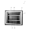
- the wafer boat 1 according to the embodiment shown in FIG. 1 includes a columnar support column 2 and a support plate 3.
- the wafer boat 1 according to the embodiment is provided with a rod-shaped member 5 different from the support column 2.
- the rod-shaped member 5 is not formed with a groove 21 as provided in the support column 2, and is used as a so-called reinforcing material.
- the wafer boat 1 according to the embodiment shown in FIGS. 5 and 6 includes a prismatic support column 2 and a support plate 3.
- the wafer boat 1 shown in FIGS. 5 and 6 does not have a rod-shaped member 5, and the support column 2 also functions as a reinforcing material, so that the weight can be reduced.
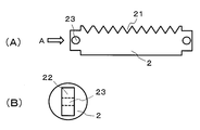
- the support column 2 shown in FIGS. 1 and 5 includes a plurality of grooves 21 for mounting the wafer.
- the size of the support column 2 is not limited, and is appropriately designed according to the number and size of wafers to be mounted.
- the support column 2 has, for example, a length (total length) of about 120 mm or more and 180 mm or less.
- the columnar column 2 may have a thickness (diameter) of about 8 mm or more and 12 mm or less.
- the prismatic column 2 may have a square cross-sectional shape in the direction perpendicular to the axis and may have a side length of about 4 mm or more and 12 mm or less.
- the support column 2 shown in FIG. 1 has only a columnar shape, and the support column 2 shown in FIG. 5 has only a prismatic shape.
- the wafer boat 1 may include both columnar and prismatic columns 2.
- the support column 2 is made of ceramics containing aluminum oxide or silicon carbide as a main component.
- the support column 2 is not limited as long as it is a ceramic containing aluminum oxide or silicon carbide as a main component.
- the term "main component” means a component that accounts for 80% by mass or more of the total 100% by mass of the components constituting the ceramics.
- the identification of each component contained in the ceramics is performed by an X-ray diffractometer using CuK ⁇ rays, and the content of each component is determined by, for example, an ICP (Inductively Coupled Plasma) emission spectroscopic analyzer or a fluorescent X-ray analyzer.
- ICP Inductively Coupled Plasma
- magnesium, silicon and calcium may be contained as oxides.
- the magnesium content is 0.034% by mass or more and 0.36% by mass or less
- the silicon content is 0.02% by mass or more and 0.7% by mass or less
- the calcium content Is 0.011% by mass or more and 0.065% by mass or less.
- the depth, width and number of grooves 21 on which the wafer is placed are not limited.
- the depth, width and number of the grooves 21 are appropriately designed according to the number and size of the wafers to be mounted.
- the cross-sectional shape of the groove 21 may be an isosceles trapezoid in which the opening side is wider than the mounting surface side. With such a shape, when the wafer is inserted into the groove 21 and placed, the risk of the wafer coming into contact with the inner side surface forming the groove 21 is reduced.
- the apex angle of the groove viewed in cross section is, for example, 18 ° or more and 42 ° or less, and particularly preferably 20 ° or more and 40 ° or less.
- the outer surface of the column 2 is at least one of a ground surface and a polished surface.
- the outer surface of the support column 2 has a surface processed in this way, the axial straightness of the outer surface, the squareness of the outer surface with respect to the end surface of the support column 2, and the like are the unground surfaces (unground surfaces). And unpolished surface). Therefore, the squareness of the virtual center surface of the groove 21 with respect to the outer peripheral surface and the parallelism between the virtual center surfaces of the adjacent grooves 21 are improved. As a result, a plurality of wafers can be regularly aligned.
- Grinding or polishing is performed by, for example, surface grinding, centerless grinding (centerless), brush polishing, buffing, or the like.
- the mounting surface of the wafer may be at least one of the ground surface and the polished surface.
- the arithmetic mean roughness Ra of the mounting surface of the wafer should be smaller than the arithmetic average roughness Ra of the outer surface.
- the arithmetic mean roughness Ra of the mounting surface of the wafer is not limited.
- the arithmetic mean roughness Ra of the mounting surface of the wafer is preferably about 0.02 ⁇ m or more and 0.3 ⁇ m or less.
- the difference is not limited.
- the difference between the arithmetic mean roughness Ra of the mounting surface of the wafer and the arithmetic average roughness Ra of the outer surface may be 0.05 ⁇ m or more.
- the arithmetic mean roughness Ra of the wafer mounting surface is about 0.02 ⁇ m or more and 0.3 ⁇ m or less, and the difference between the arithmetic mean roughness Ra of the wafer mounting surface and the arithmetic mean roughness Ra of the outer surface is 0. If it is 05 ⁇ m or more, the possibility that the wafer is damaged when the wafer is placed in the groove 21 can be further reduced.
- the arithmetic average roughness Ra of the mounting surface of the wafer and the arithmetic average roughness Ra of the outer surface are both laser microscopes having a measurement mode compliant with JIS B 0601: 2001 (manufactured by KEYENCE CORPORATION, VK-X1100 or its own). It can be measured using the successor model).
- the measurement conditions are as follows: first, the magnification is 480 times, the cutoff value ⁇ s is absent, the cutoff value ⁇ c is 0.08 mm, the cutoff value ⁇ f is absent, and one place is per place from the mounting surface and the outer surface to be measured.
- the measurement range of each is set to 705 ⁇ m ⁇ 530 ⁇ m.
- a representative portion showing the characteristics of the surface may be selected from the surface observed at a magnification of 480 times.
- the length per wire is 560 m, and the direction of the wire may be the same as the direction of the polishing streaks and the polishing streaks observed on the mounting surface and the outer surface.
- Both ends of the support column 2 have flat plate-shaped engaging portions 22 as shown in FIG. 2 (B).
- the flat plate-shaped engaging portion 22 is formed with a through hole 23 for inserting the male screw 4 in the thickness direction. That is, it is formed in a direction perpendicular to the axial direction (longitudinal direction) of the support column 2.
- the through hole 23 is formed on the same axis as the female screw (not shown) provided in the support plate 3, and the male screw 4 is inserted into the through hole 23 and attached to the support plate 3.
- the manufacturing method of the support column 2 is not limited, and is manufactured as follows, for example. First, a case where a support column is formed of ceramics containing aluminum oxide as a main component will be described.
- Aluminum oxide powder (purity 99.9% by mass or more) as a main component and each powder of magnesium hydroxide, silicon oxide and calcium carbonate are put into a pulverizing mill together with a solvent (ion-exchanged water). After pulverizing the powder until the average particle size (D50) becomes 1.5 ⁇ m or less, an organic binder and a dispersant for dispersing the aluminum oxide powder are added and mixed to obtain a slurry.
- the content of the magnesium hydroxide powder in a total of 100% by mass of the powder is 0.05% by mass or more and 0.53% by mass or less, and the content of the silicon oxide powder is 0.02% by mass or more and 0.7% by mass.
- the content of the calcium carbonate powder is 0.02% by mass or more and 0.12% by mass or less, and the balance is aluminum oxide powder and unavoidable impurities.
- the organic binder include acrylic emulsions, polyvinyl alcohols, polyethylene glycols, polyethylene oxides and the like.
- the slurry is spray-granulated to obtain granules whose main component is aluminum oxide.
- the granules are filled in the molding space in the cold hydrostatic pressure presser, and the molding pressure is pressurized to, for example, 78 MPa to 128 MPa to obtain a cylindrical or prismatic molded product.
- the firing atmosphere is an atmospheric atmosphere, the firing temperature is 1500 ° C. or higher and 1700 ° C. or lower, and the holding time is 4 hours or longer.
- a columnar sintered body can be obtained by firing the molded product for 6 hours or less.
- the support is formed of ceramics containing silicon carbide as the main component
- Coarse-granular powder and fine-granular powder are prepared as silicon carbide powder, and the silicon carbide powder is put into a pulverizing mill together with a solvent and a dispersant, and pulverized and mixed to obtain a slurry.
- the pulverization and mixing time is 40 hours or more and 60 hours or less.
- the range of the particle size of the fine granular powder and the coarse granular powder after pulverization and mixing is 0.4 ⁇ m or more and 4 ⁇ m or less, and 11 ⁇ m or more and 34 ⁇ m or less.
- a sintering aid composed of boron carbide powder and amorphous carbon powder or phenol resin and a binder were added to and mixed with the obtained slurry, and then spray-dried to carbonize the main component.
- a sintering aid composed of boron carbide powder and amorphous carbon powder or phenol resin and a binder were added to and mixed with the obtained slurry, and then spray-dried to carbonize the main component.
- a flat plate-shaped engaging portion having through holes is formed at both ends of the molded body obtained by cutting the molded body obtained by molding the granules by the method described above.
- a degreased body is obtained in a nitrogen atmosphere at a temperature of 450 ° C. to 650 ° C. and a holding time of 2 hours or more and 10 hours or less.
- a columnar sintered body can be obtained by firing the degreased body with the firing atmosphere set to a reduced pressure atmosphere of an inert gas, the firing temperature set to 1800 ° C. or higher and 2200 ° C. or lower, and the holding time set to 3 hours or longer and 6 hours or lower. ..
- a columnar column By processing the outer surface of the above-mentioned columnar sintered body by centerless grinding (centerless) with a rotary grindstone, brush polishing, buffing, etc., a columnar column can be formed.
- the sintered body is prismatic, it can be made into a prismatic column by processing the outer surface by surface grinding.
- Grooves are formed by V-groove grinding with a rotary grindstone whose outer peripheral tip is formed at an acute angle. Brush polishing, buffing, etc. may be performed as necessary.
- the male screw 4 is screwed into the female screw provided on the support plate 3 through the through hole 23 formed in the flat plate-shaped engaging portion 22. Since the support column 2 is mechanically attached to the support plate 3 by a screw, the wafer is unlikely to become unstable even if it is conveyed. As a result, the possibility of damaging the wafer can be further reduced.
- the support plate 3 is used to support (fix) both ends of the support column 2.
- the size of the support plate 3 is appropriately designed according to the size of the wafer to be placed, the length of the support column 2, and the like.
- the support plate 3 is made of, for example, ceramics. Examples of the ceramics include ceramics containing aluminum oxide or silicon carbide as a main component.
- at least one of the support plates 3 may have a hollow structure. Having a hollow structure improves convection of the cleaning liquid when used as a cleaning component. Further, since the residual liquid at the time of drying is reduced, the cleaning efficiency is improved.
- the shape of the support plate 3 is not limited as long as it can support both ends of the support column 2.
- the peripheral edge portion of the support plate 3 may be formed in an uneven shape so as to match the shape of both end portions of the support column 2.
- the support column 2 is arranged so that both ends of the support column 2 are located on the uneven portion, and is fixed by the male screw 4 as described above, for example.
- the male screw 4 is also made of, for example, ceramics. Examples of the ceramics include ceramics containing aluminum oxide or silicon carbide as a main component.
- the manufacturing method of the support plate 3 is not limited, and is manufactured as follows, for example. First, the granules obtained by the above method are filled in the molding space in the cold hydrostatic pressure presser. A plate-shaped molded product is obtained by pressurizing the molding pressure to, for example, 78 MPa or more and 128 MPa or less. Next, the molded body is formed into a shape that serves as a precursor of the support plate 3 by cutting or the like. Then, a sintered body can be obtained by appropriately selecting firing conditions according to the main component and firing the precursor. Each surface of the sintered body may be ground or polished as needed.
- the support column 2, the support plate 3, and the male screw 4 may be formed of ceramics having different main components, or may be formed of the same ceramics as the main components. Ceramics having the same principal component do not have to have the same content of the principal component, and the content of the principal component may be different. For example, if the main component is aluminum oxide, the content of aluminum oxide may be different.
- the proportion of the main component contained in each member is not limited.
- the content of the main component it is preferable to minimize the content of the main component of the male screw 4.
- the support column 2 and the support plate 3 having a larger surface area than the male screw 4 have a larger area in contact with the cleaning liquid. Therefore, by increasing the content (increasing the purity) of the main components of the support column 2 and the support plate 3, corrosion can be suppressed even if the columns 2 and the support plate 3 are washed with an acid or an alkali. As a result, the wafer boat 1 according to the embodiment can be used for a long period of time.
- the content of the main component is not limited as long as the content of the main component of the male screw 4 is minimized.
- the difference between the main component contained in the support column 2 and the main component contained in the male screw 4 may be 0.15% by mass or more. By having such a difference, corrosion can be further suppressed and it can be used for a longer period of time.
- At least one of the support column 2, the support plate 3, and the male screw 4 may be made of ceramics having closed pores.
- the value (A) obtained by subtracting the average value of the equivalent circle diameters of the closed pores from the distance between the centers of gravity of the adjacent closed pores is preferably 20 ⁇ m or more and 85 ⁇ m or less.
- this value (A) is 20 ⁇ m or more, the void portions are dispersed and arranged in the ceramic without being densely packed. Therefore, higher mechanical properties are exhibited.
- the value (A) is 85 ⁇ m or less, workability such as polishing is further improved. Further, when the value (A) is in such a range, the distance between the adjacent closed pores becomes narrow. Therefore, it is possible to suppress the expansion of microcracks caused by thermal shock or the like.
- the value (A) can be obtained by the following method. First, the columns 2 are polished on a copper plate from a cross section perpendicular to the longitudinal direction to a depth direction (longitudinal direction) using diamond abrasive grains having an average particle diameter D 50 of 3 ⁇ m. Then, a polished surface is obtained by polishing with a tin plate using diamond abrasive grains having an average particle diameter D 50 of 0.5 ⁇ m.
- a range with an area of 0.105 mm 2 (horizontal length 374 ⁇ m, vertical length 280 ⁇ m) is CCD.
- CCD CCD
- the distance between the centers of gravity of the open pores is measured by using the image analysis software "A image-kun (ver2.52)" (registered trademark, manufactured by Asahi Kasei Engineering Co., Ltd.). Just find the distance.
- a image-kun registered trademark, manufactured by Asahi Kasei Engineering Co., Ltd.
- a threshold value indicating the brightness and darkness of the image may be 86, the brightness may be dark, the small figure removal area may be 1 ⁇ m 2 , and a noise removal filter may be provided.
- the threshold value may be adjusted according to the brightness of the observed image. The lightness is dark, the binarization method is manual, the small figure removal area is 1 ⁇ m 2, and there is a noise removal filter, and the threshold value is set so that the markers appearing in the observation image match the shape of the pores. Should be adjusted.
- the equivalent circle diameter of the closed pores can be obtained by the following method.
- the equivalent circle diameter of the closed pores may be obtained by a technique called particle analysis.
- the setting conditions of this method may be the same as the setting conditions used in the distance between the centers of gravity of the dispersion measurement.
- a polished surface may be prepared in the thickness direction of the support plate 3 by the same method as described above, and the value (A) may be obtained for this polished surface by the same method as described above.
- a polished surface is prepared in the depth direction (longitudinal direction) from the cross section perpendicular to the longitudinal direction of the male screw 4 by the same method as described above, and the polished surface is targeted by the same method as described above. The value (A) may be obtained.
- the support plate 3 and the male screw 4 having a value (A) of 20 ⁇ m or more and 85 ⁇ m or less, when obtaining ceramics whose main component is aluminum oxide, the firing temperature is 1500 ° C. or more and 1600 ° C. or less, and the firing atmosphere.
- heat treatment is performed by setting the heat treatment temperature to 1300 ° C. or more and 1600 ° C. or less, the heat treatment atmosphere to an argon atmosphere, and the pressure to 90 MPa or more and 300 MPa or less. Just do it.
- the wafer boat 1 according to the embodiment can mount a plurality of wafers in a regularly aligned state.
- the wafer boat 1 according to such an embodiment is provided in a heat treatment apparatus for heat-treating a wafer, a cleaning apparatus for cleaning a wafer, and the like.
- the wafer boat according to the present disclosure is not limited to the above-described embodiment.
- the wafer boat 1 according to the embodiment is provided with four columns 2.
- at least two columnar columns may be provided as long as they are arranged so as to hold the wafer.
- the support column 2 is supported on the support plate 3 by using a male screw 4.
- the means for supporting the columnar columns on the support plate is not limited, and the columnar columns may be supported by using, for example, an adhesive, a glass bond, a diffusion bond, or the like.
- the peripheral edge portion of the support plate 3 is formed in an uneven shape so as to match the shape of both end portions of the support plate 2.
- the shape of the support plate is not limited, and the peripheral edge portion of the support plate may not be formed in an uneven shape.
- the wafer boat 1 according to the embodiment is provided with a rod-shaped member 5 different from the support column 2 as a reinforcing material.
- a rod-shaped member is a member that is arbitrarily used, and is not necessarily a member that must be used.
Landscapes
- Engineering & Computer Science (AREA)
- Chemical & Material Sciences (AREA)
- Ceramic Engineering (AREA)
- Manufacturing & Machinery (AREA)
- Materials Engineering (AREA)
- Organic Chemistry (AREA)
- Structural Engineering (AREA)
- Inorganic Chemistry (AREA)
- Physics & Mathematics (AREA)
- Chemical Kinetics & Catalysis (AREA)
- Condensed Matter Physics & Semiconductors (AREA)
- General Physics & Mathematics (AREA)
- Power Engineering (AREA)
- Microelectronics & Electronic Packaging (AREA)
- Computer Hardware Design (AREA)
- Thermal Sciences (AREA)
- Container, Conveyance, Adherence, Positioning, Of Wafer (AREA)
- Packaging Frangible Articles (AREA)
Abstract
本開示に係るウェハーボートは、ウェハーを載置するための複数の溝を備えた複数の柱状の支柱と、支柱の両端部をそれぞれ支持する支持板とを備える。支柱が、酸化アルミニウムまたは炭化ケイ素を主成分とするセラミックスで形成されており、支柱の外側面が研削面および研磨面の少なくとも一方である。
Description
本開示は、ウェハーボートに関する。
従来、LSIなどの半導体デバイスの製造工程において、半導体ウェハー(以下、単に「ウェハー」と記載する場合がある)の表面に酸化膜を形成したり、ドーパントを拡散させたりするために、ウェハーを1200℃程度の高温で熱処理する工程が含まれる。このような熱処理工程において、複数のウェハーを水平方向に所定間隔で載置するために、特許文献1に記載のようなウェハーボートが使用される。
本開示に係るウェハーボートは、ウェハーを載置するための複数の溝を備えた複数の柱状の支柱と、支柱の両端部をそれぞれ支持する支持板とを備える。支柱が、酸化アルミニウムまたは炭化ケイ素を主成分とするセラミックスで形成されており、支柱の外側面が研削面および研磨面の少なくとも一方である。
特許文献1に記載のような従来のウェハーボートは、製造方法などに起因する支持棒(支柱)のうねりや反りを生じることがある。その結果、従来のウェハーボートは、支持棒の外周面の軸方向の真直度や、支持棒の端面に対する外周面の直角度などを精度よく保つことができない。したがって、ウェハーを載置するための溝を正確に形成するのが困難である。
本開示に係るウェハーボートは、上記のように、支柱の外測面が研削面および研磨面の少なくとも一方である。そのため、支柱の軸方向の真直度や、支柱の端面に対する外側面の直角度などが、焼き放し面である場合よりも向上する。その結果、外側面に対する溝の仮想中心面の直角度および隣り合う溝の仮想中心面同士の平行度が向上する。したがって、本開示に係るウェハーボートを使用すると、複数のウェハーを規則正しく整列した状態で載置させることができる。
本開示の一実施形態に係るウェハーボートを、図1~6に基づいて説明する。図1に示す一実施形態に係るウェハーボート1は、円柱状の支柱2と支持板3とを備える。一実施形態に係るウェハーボート1には、図1に示すように、支柱2とは異なる棒状部材5が設けられている。この棒状部材5には、支柱2が備えるような溝21は形成されておらず、いわゆる補強材として使用されている。
図5および6に示す一実施形態に係るウェハーボート1は、角柱状の支柱2と支持板3とを備える。図5、6に示すウェハーボート1は、棒状部材5がなく、支柱2が補強材としても機能するため、軽量化することができる。
図1および5に示す支柱2は、ウェハーを載置するための複数の溝21を備える。支柱2の大きさは限定されず、載置されるウェハーの数や大きさに応じて適宜設計される。支柱2は、例えば、120mm以上180mm以下程度の長さ(全長)を有する。円柱状の支柱2は、8mm以上12mm以下程度の太さ(直径)を有していてもよい。角柱状の支柱2は、軸に垂直な方向における断面形状が正方形であって、1辺の長さが4mm以上12mm以下程度であってもよい。
図1に示す支柱2は円柱状のみ、図5に示す支柱2は角柱状のみである。しかし、ウェハーボート1は、円柱状および角柱状両方の支柱2を備えていてもよい。
支柱2は、酸化アルミニウムまたは炭化ケイ素を主成分とするセラミックスで形成されている。支柱2は、酸化アルミニウムまたは炭化ケイ素を主成分とするセラミックスであれば、限定されない。本明細書において「主成分」とは、セラミックスを構成する成分の合計100質量%における80質量%以上を占める成分を意味する。セラミックスに含まれる各成分の同定は、CuKα線を用いたX線回折装置で行い、各成分の含有量は、例えばICP(InductivelyCoupled Plasma)発光分光分析装置または蛍光X線分析装置により求められる。
セラミックスが酸化アルミニウムを主成分とする場合、マグネシウム、珪素およびカルシウムを酸化物として含んでいてもよい。酸化物に換算すると、例えば、マグネシウムの含有量は、0.034質量%以上0.36質量%以下、珪素の含有量は、0.02質量%以上0.7質量%以下、カルシウムの含有量は、0.011質量%以上0.065質量%以下である。
ウェハーを載置するための溝21について、深さ、幅および数は限定されない。溝21の深さ、幅および数は、載置されるウェハーの数や大きさに応じて適宜設計される。
溝21の断面形状は、開口側が載置面側よりも幅の広い等脚台状であってもよい。このような形状であれば、ウェハーを溝21に挿入して載置する場合、溝21を形成する内側面にウェハーを接触させるおそれが低減する。断面視した溝の頂角は、例えば、18°以上42°以下であり、特に、20°以上40°以下であるとよい。
一実施形態に係るウェハーボート1において、支柱2の外側面は、研削面および研磨面の少なくとも一方である。支柱2の外側面がこのように加工された面を有していると、外側面の軸方向の真直度や、支柱2の端面に対する外側面の直角度などが、焼き放し面(未研削面および未研磨面)である場合よりも向上する。そのため、外周面に対する溝21の仮想中心面の直角度および隣り合う溝21の仮想中心面同士の平行度が向上する。その結果、複数のウェハーを規則的に整列させることができる。
研削または研磨は、例えば、平面研削、心なし研削(センタレス)、ブラシ研磨、バフ研磨などによって行われる。
支柱2に備えられた溝21において、ウェハーの載置面が、研削面および研磨面の少なくとも一方であってもよい。この場合、ウェハーの載置面の算術平均粗さRaは、外側面の算術平均粗さRaよりも小さい方がよい。支柱2に備えられた溝21が、このような構造を有することによって、ウェハーを溝21に載置した場合に、ウェハーが損傷する可能性を低減することができる。
支柱2に備えられた溝21において、ウェハーの載置面の算術平均粗さRaは限定されない。例えば、ウェハーの載置面の算術平均粗さRaは、0.02μm以上0.3μm以下程度であるのがよい。さらに、ウェハーの載置面の算術平均粗さRaは、外側面の算術平均粗さRaよりも小さければ、その差は限定されない。例えば、ウェハーの載置面の算術平均粗さRaと外側面の算術平均粗さRaとの差が0.05μm以上であってもよい。ウェハーの載置面の算術平均粗さRaが0.02μm以上0.3μm以下程度であり、ウェハーの載置面の算術平均粗さRaと外側面の算術平均粗さRaとの差が0.05μm以上であれば、ウェハーを溝21に載置した場合に、ウェハーが損傷する可能性をより低減することができる。
ウェハーの載置面の算術平均粗さRaおよび外側面の算術平均粗さRaは、いずれもJIS B 0601:2001に準拠した測定モードを有するレーザ顕微鏡((株)キーエンス製、VK-X1100またはその後継機種)を用いて測定することができる。測定条件としては、まず、倍率を480倍、カットオフ値λsを無し、カットオフ値λcを0.08mm、カットオフ値λfを無し、測定対象とする載置面および外側面から1か所当たりの測定範囲をそれぞれ705μm×530μmに設定する。ここで、測定範囲の設定にあたっては、倍率を480倍として観察した表面のうち、その表面の特徴を示す代表的な部分を選択すればよい。
そして、測定範囲において、測定対象とする線を略等間隔に4本引いて、表面粗さ計測を行い、算術平均粗さRaの平均値を各面毎に求め、両者を比べればよい。線1本当たりの長さは、560mであり、線の方向は、載置面および外側面で観察される研磨筋や研磨筋との方向と同じ方向にすればよい。
支柱2の両端部は、図2(B)に示すように平板状の係合部22を有している。平板状の係合部22には、厚み方向に雄ねじ4を挿入するための通し穴23が形成されている。すなわち、支柱2の軸方向(長手方向)と垂直な方向に形成されている。通し穴23は、支持板3に設けられた雌ねじ(図示しない)と同一軸心上に形成され、雄ねじ4が通し穴23に挿入されて支持板3に取り付けられる。
支柱2の製造方法は限定されず、例えば、下記のようにして製造される。まず、酸化アルミニウムを主成分とするセラミックスで支柱を形成する場合について説明する。主成分である酸化アルミニウム粉末(純度99.9質量%以上)と、水酸化マグネシウム、酸化珪素および炭酸カルシウムの各粉末とを、粉砕用ミルに溶媒(イオン交換水)とともに投入する。粉末の平均粒径(D50)が1.5μm以下になるまで粉砕した後、有機結合剤と酸化アルミニウム粉末を分散させる分散剤とを添加し、混合してスラリーを得る。
ここで、上記粉末の合計100質量%における水酸化マグネシウム粉末の含有量は0.05質量%以上0.53質量%以下、酸化珪素粉末の含有量は0.02質量%以上0.7質量%以下、炭酸カルシウム粉末の含有量は0.02質量%以上0.12質量%以下であり、残部が酸化アルミニウム粉末および不可避不純物である。有機結合剤としては、例えば、アクリルエマルジョン、ポリビニールアルコール、ポリエチレングリコール、ポリエチレンオキサイドなどが挙げられる。
次に、スラリーを噴霧造粒して主成分が酸化アルミニウムからなる顆粒を得る。この顆粒を冷間静水圧加圧装置内の成形用空間に充填して、成形圧を、例えば、78MPa~128MPaとして加圧することにより円柱状または角柱状の成形体を得る。次に、切削などにより成形体の両端部に、通し穴を有する平板状の係合部を形成した後、焼成雰囲気を大気雰囲気、焼成温度を1500℃以上1700℃以下、保持時間を4時間以上6時間以下として、成形体を焼成することによって柱状の焼結体を得ることができる。
炭化珪素を主成分とするセラミックスで支柱を形成する場合について説明する。炭化珪素粉末として粗粒状粉末および微粒状粉末を準備し、炭化珪素粉末を、粉砕用ミルに溶媒と分散剤とともに投入し、粉砕混合してスラリーとする。粉砕混合の時間は40時間以上60時間以下である。粉砕混合した後の微粒状粉末および粗粒状粉末のそれぞれの粒径の範囲は0.4μm以上4μm以下、および11μm以上34μm以下である。
次に、得られたスラリーに、炭化硼素粉末および非晶質状の炭素粉末またはフェノール樹脂からなる焼結助剤と、バインダとを添加して混合した後、噴霧乾燥することで主成分が炭化珪素からなる顆粒を得る。この顆粒を上述した方法で成形した成形体を切削などにより成形体の両端部に、通し穴を有する平板状の係合部を形成する。その後、窒素雰囲気中、温度を450℃~650℃、保持時間を2時間以上10時間以下として脱脂体を得る。次に、焼成雰囲気を不活性ガスの減圧雰囲気、焼成温度を1800℃以上2200℃以下、保持時間を3時間以上6時間以下として脱脂体を焼成することによって柱状の焼結体を得ることができる。
上述した柱状の焼結体の外側面を回転砥石による心なし研削(センタレス)、ブラシ研磨、バフ研磨などによって加工することによって、円柱状の支柱とすることができる。焼結体が角柱状である場合、平面研削により、外側面を加工することによって、角柱状の支柱とすることができる。溝は、外周先端が鋭角状に形成された回転砥石によるV溝研削によって形成する。必要に応じてブラシ研磨、バフ研磨などを施せばよい。載置面が外側面よりも小さい算術平均粗さRaを有するウェハーボートを得る場合、例えば、溝の形成で用いる回転砥石の粒度を、外側面の形成で用いる回転砥石の粒度よりも細かくすればよい。
雄ねじ4が平板状の係合部22に形成された通し穴23を介して、支持板3に設けられた雌ねじに螺合される。支柱2が、ねじによって支持板3に機械的に取り付けられた状態となるため、搬送してもウェハーが不安定になりにくい。その結果、ウェハーが損傷する可能性をより低減することができる。
支持板3は、支柱2の両端部を支持(固定)するために使用される。支持板3の大きさは、載置されるウェハーの大きさや支柱2の長さなどに応じて、適宜設計される。支持板3は、例えばセラミックスで形成されている。セラミックスとしては、酸化アルミニウムまたは炭化ケイ素を主成分とするセラミックスなどが挙げられる。軽量化を目的として、支持板3の少なくとも1つは、中空構造を有していてもよい。中空構造を有していると、洗浄用の部品として用いる場合、洗浄液の対流が改善する。さらに、乾燥時の残液が少なくなるため、洗浄効率が良好になる。
支持板3の形状は、支柱2の両端部を支持し得る形状であれば、限定されない。例えば、図3に示すように、支柱2の両端部の形状に整合させて、支持板3の周縁部を凹凸状に形成してもよい。この凹凸部分には、図4に示すように支柱2の両端部が位置するように支柱2が配置され、例えば、上述のように雄ねじ4で固定される。雄ねじ4も、例えばセラミックスで形成されている。セラミックスとしては、酸化アルミニウムまたは炭化ケイ素を主成分とするセラミックスなどが挙げられる。
支持板3の製造方法は限定されず、例えば、下記のようにして製造される。まず、上述した方法で得られた顆粒を冷間静水圧加圧装置内の成形用空間に充填する。成形圧を、例えば、78MPa以上128MPa以下として加圧することにより板状の成形体を得る。次に、切削などにより成形体を支持板3の前駆体となる形状にする。その後、主成分に応じて焼成条件を適宜選択して、上記前駆体を焼成することによって焼結体を得ることができる。この焼結体の各表面は、必要に応じて研削または研磨を施せばよい。
支柱2、支持板3および雄ねじ4は、それぞれ主成分の異なるセラミックスで形成されていてもよく、主成分が同じセラミックスで形成されていてもよい。主成分が同じセラミックスとは、主成分の含有量まで同じである必要はなく、主成分の含有量は異なっていてもよい。例えば、主成分が酸化アルミニウムであれば、酸化アルミニウムの含有量は異なっていてもよい。
支柱2、支持板3および雄ねじ4が、同じ主成分のセラミックスで形成されている場合、それぞれの部材に含まれる主成分の割合は限定されない。例えば、主成分の含有量については、雄ねじ4の主成分の含有量を最も少なくするのがよい。例えば、一実施形態に係るウェハーボート1を洗浄する場合、雄ねじ4と比べて大きな表面積を有する支柱2および支持板3は、洗浄液と接触する面積が大きくなる。そのため、支柱2および支持板3の主成分の含有量を高める(純度を高くする)ことによって、酸やアルカリで洗浄しても腐食を抑制することができる。その結果、一実施形態に係るウェハーボート1を長期間にわたって使用することができる。
主成分の含有量については、雄ねじ4の主成分の含有量を最も少なくすれば限定されない。例えば、支柱2に含まれる主成分と雄ねじ4に含まれる主成分との差が0.15質量%以上であってもよい。このような差を有することによって、腐食をより抑制することができ、より長期間にわたって使用することができる。
雄ねじ4の完全ねじ部および支持板3に設けられた雌ねじの完全ねじ部の表面、ならびに支柱2の両端部に設けられた平板状の係合部22に形成された通し穴23の内壁面の少なくとも一方が、焼き放し面であってもよい。焼き放し面は、純水に対する接触角が低く、親水性が高くなるため、雄ねじ4が雌ねじに螺合した状態でも、一実施形態に係るウェハーボート1を効率よく洗浄することができる。特に、雄ねじ4の完全ねじ部および支持板3に設けられた雌ねじの完全ねじ部の表面が焼き放し面であるのがよい。完全ねじ部の表面は大きな凹凸を有しているため、結合力が強く、耐衝撃性や耐振性に対する信頼性が向上する。
支柱2、支持板3および雄ねじ4の少なくとも1種が、閉気孔を有するセラミックスで形成されていてもよい。この場合、隣り合う閉気孔の重心間距離から閉気孔の円相当径の平均値を引いた値(A)が20μm以上85μm以下であるのがよい。この値(A)が20μm以上であれば、セラミックス中に空隙部分が密集せずに分散して配置されている。そのため、より高い機械的特性が発揮される。一方、値(A)が85μm以下であれば、研磨などの加工性がより向上する。さらに、値(A)がこのような範囲であれば、隣り合う閉気孔の間隔が狭くなる。そのため、熱衝撃などによって生じるマイクロクラックの伸展を抑制することができる。
値(A)は、以下の方法で求めることができる。まず、支柱2の長手方向に垂直な断面から深さ方向(長手方向)に、平均粒径D50が3μmのダイヤモンド砥粒を用いて銅盤にて研磨する。その後、平均粒径D50が0.5μmのダイヤモンド砥粒を用いて錫盤にて研磨することにより研磨面を得る。
研磨面を200倍の倍率で観察し、平均的な範囲を選択して、例えば、面積が0.105mm2(横方向の長さが374μm、縦方向の長さが280μm)となる範囲をCCDカメラで撮影して、観察像を得る。この観察像を対象として、画像解析ソフト「A像くん(ver2.52)」(登録商標、旭化成エンジニアリング(株)製)を用いて分散度計測の重心間距離法という手法で開気孔の重心間距離を求めればよい。以下、画像解析ソフト「A像くん」と記載した場合、旭化成エンジニアリング(株)製の画像解析ソフトを示す。
この手法の設定条件としては、例えば、画像の明暗を示す指標であるしきい値を86、明度を暗、小図形除去面積を1μm2、雑音除去フィルタを有とすればよい。観察像の明るさに応じて、しきい値を調整してもよい。明度を暗とし、2値化の方法を手動とし、小図形除去面積を1μm2および雑音除去フィルタを有とした上で、観察像に現れるマーカーが気孔の形状と一致するように、しきい値を調整すればよい。
閉気孔の円相当径は、以下の方法で求めることができる。上記観察像を対象として、粒子解析という手法で閉気孔の円相当径を求めればよい。この手法の設定条件も分散度計測の重心間距離法で用いた設定条件と同じにすればよい。
支持板3の場合、支持板3の厚み方向に上述した方法と同じ方法で研磨面を作製し、この研磨面を対象として、上述した方法と同じ方法で値(A)を求めればよい。雄ねじ4の場合、雄ねじ4の長手方向に垂直な断面から深さ方向(長手方向)に上述した方法と同じ方法で研磨面を作製し、この研磨面を対象として、上述した方法と同じ方法で値(A)を求めればよい。
値(A)が20μm以上85μm以下である、支柱2、支持板3および雄ねじ4を得るには、主成分が酸化アルミニウムであるセラミックスを得る場合、焼成温度を1500℃以上1600℃以下、焼成雰囲気を大気雰囲気、保持時間を5時間以上6時間以下として、成形体を焼成した後、例えば、熱処理温度を1300℃以上1600℃以下、熱処理の雰囲気をアルゴン雰囲気、圧力を90MPa以上300MPa以下として熱処理すればよい。
一実施形態に係るウェハーボート1は、上述のように、複数のウェハーを規則正しく整列した状態で載置させることができる。このような一実施形態に係るウェハーボート1は、ウェハーを熱処理するための熱処理装置、ウェハーを洗浄するための洗浄装置などに備えられる。
本開示に係るウェハーボートは、上述の一実施形態に限定されない。例えば、一実施形態に係るウェハーボート1には、4つの支柱2が備えられている。しかし、本開示に係るウェハーボートにおいて柱状の支柱は、ウェハーを保持し得るように配置されれば、少なくとも2つ備えられていればよい。
一実施形態に係るウェハーボート1において、支柱2は支持板3に雄ねじ4を用いて支持されている。しかし、本開示に係るウェハーボートにおいて、柱状の支柱を支持板に支持する手段は限定されず、例えば、接着剤、ガラス接合、拡散接合などを用いて支持されていてもよい。
一実施形態に係るウェハーボート1において、支持板3の周縁部は、支柱2の両端部の形状に整合させて凹凸状に形成されている。しかし、本開示に係るウェハーボートにおいて、支持板の形状は限定されず、支持板の周縁部は凹凸状に形成されていなくてもよい。
一実施形態に係るウェハーボート1には、補強材として支柱2とは異なる棒状部材5が設けられている。しかし、本開示に係るウェハーボートにおいて、このような棒状部材は任意で使用される部材であり、必ずしも使用しなければならない部材ではない。
1 ウェハーボート
2 支柱
21 溝
22 平板状の係合部
23 通し穴
3 支持板
4 雄ねじ
5 棒状部材
2 支柱
21 溝
22 平板状の係合部
23 通し穴
3 支持板
4 雄ねじ
5 棒状部材
Claims (12)
- ウェハーを載置するための複数の溝を備えた複数の柱状の支柱と、該支柱の両端部をそれぞれ支持する支持板とを備え、
前記支柱が、酸化アルミニウムまたは炭化ケイ素を主成分とするセラミックスで形成されており、前記支柱の外側面は研削面および研磨面の少なくとも一方である、
ウェハーボート。 - 前記溝において前記ウェハーを載置する載置面が、研削面および研磨面の少なくとも一方であって、前記載置面が前記外側面よりも小さい算術平均粗さRaを有する請求項1に記載のウェハーボート。
- 前記溝の断面形状が前記載置面側より開口側の幅が広い等脚台形状である、請求項1または2に記載のウェハーボート。
- 前記支柱の両端部が、厚み方向に通し穴を有する平板状の係合部を備えており、
前記支持板には、それぞれ前記通し穴の軸心上に雌ねじが設けられており、
雄ねじが、前記通し穴を介して前記雌ねじに螺合されている、
請求項1~3のいずれかに記載のウェハーボート。 - 前記支柱、前記支持板および前記雄ねじが、同じ主成分のセラミックスで形成されており、前記主成分の含有量について、前記雄ねじが最も少ない請求項4に記載のウェハーボート。
- 前記支柱に含まれる主成分の含有量が、前記雄ねじに含まれる主成分の含有量より少なくとも0.15質量%多い請求項5に記載のウェハーボート。
- 前記雌ねじの完全ねじ部および前記雄ねじの完全ねじ部の表面、ならびに前記通し穴の内壁面の少なくとも1種が、焼き放し面である請求項4~6のいずれかに記載のウェハーボート。
- 前記通し穴が、前記支柱の軸方向に沿った長穴である請求項4~7のいずれかに記載のウェハーボート。
- 前記支柱、前記支持板および前記雄ねじの少なくとも1種が、閉気孔を有するセラミックスで形成されており、隣り合う該閉気孔の重心間距離から前記閉気孔の円相当径の平均値を引いた値(A)が20μm以上85μm以下である請求項4~8のいずれかに記載のウェハーボート。
- 前記支持板の少なくとも1つが、中空構造を有している請求項1~9のいずれかに記載のウェハーボート。
- 請求項1~10のいずれかに記載のウェハーボートを備える熱処理装置。
- 請求項1~10のいずれかに記載のウェハーボートを備える洗浄装置。
Priority Applications (3)
| Application Number | Priority Date | Filing Date | Title |
|---|---|---|---|
| EP21750556.9A EP4101826A4 (en) | 2020-02-07 | 2021-02-05 | WAFER BOAT |
| JP2021576198A JP7450646B2 (ja) | 2020-02-07 | 2021-02-05 | ウェハーボート |
| US17/798,049 US20230111655A1 (en) | 2020-02-07 | 2021-02-05 | Wafer boat |
Applications Claiming Priority (2)
| Application Number | Priority Date | Filing Date | Title |
|---|---|---|---|
| JP2020020013 | 2020-02-07 | ||
| JP2020-020013 | 2020-02-07 |
Publications (1)
| Publication Number | Publication Date |
|---|---|
| WO2021157722A1 true WO2021157722A1 (ja) | 2021-08-12 |
Family
ID=77200678
Family Applications (1)
| Application Number | Title | Priority Date | Filing Date |
|---|---|---|---|
| PCT/JP2021/004416 WO2021157722A1 (ja) | 2020-02-07 | 2021-02-05 | ウェハーボート |
Country Status (5)
| Country | Link |
|---|---|
| US (1) | US20230111655A1 (ja) |
| EP (1) | EP4101826A4 (ja) |
| JP (1) | JP7450646B2 (ja) |
| TW (1) | TWI770810B (ja) |
| WO (1) | WO2021157722A1 (ja) |
Cited By (2)
| Publication number | Priority date | Publication date | Assignee | Title |
|---|---|---|---|---|
| WO2023100821A1 (ja) * | 2021-11-30 | 2023-06-08 | 京セラ株式会社 | 高さ調節部材、熱処理装置および静電チャック装置 |
| TWI850883B (zh) | 2021-11-30 | 2024-08-01 | 日商京瓷股份有限公司 | 高度調節構件、熱處理裝置及靜電夾盤裝置 |
Citations (10)
| Publication number | Priority date | Publication date | Assignee | Title |
|---|---|---|---|---|
| JPS53148283A (en) * | 1977-05-30 | 1978-12-23 | Toshiba Ceramics Co | Silicon wafer jig |
| JPS6161831U (ja) * | 1984-09-26 | 1986-04-25 | ||
| JPH02104630U (ja) * | 1988-11-25 | 1990-08-20 | ||
| JPH0595040A (ja) * | 1991-08-27 | 1993-04-16 | Mitsubishi Materials Corp | シリコンウエーハの支持治具 |
| JPH08102486A (ja) * | 1994-09-30 | 1996-04-16 | Shin Etsu Handotai Co Ltd | ウエーハ支持ボート |
| JPH09275078A (ja) * | 1996-04-05 | 1997-10-21 | Sumitomo Metal Ind Ltd | シリコンウエハ保持治具 |
| JPH11126755A (ja) | 1997-10-22 | 1999-05-11 | Sumitomo Metal Ind Ltd | 半導体熱処理用ボートの製造方法 |
| JP2000119079A (ja) * | 1998-08-11 | 2000-04-25 | Toshiba Ceramics Co Ltd | 半導体熱処理用Si−SiC製部材およびその製造方法 |
| JP2008010589A (ja) * | 2006-06-28 | 2008-01-17 | Kobe Steel Ltd | ガラス状炭素製ウェハボートおよびその製造方法 |
| JP2019004096A (ja) * | 2017-06-19 | 2019-01-10 | 東京エレクトロン株式会社 | 基板保持具及びこれを用いた基板処理装置 |
Family Cites Families (4)
| Publication number | Priority date | Publication date | Assignee | Title |
|---|---|---|---|---|
| DE2349512C3 (de) * | 1973-10-02 | 1978-06-08 | Siemens Ag, 1000 Berlin Und 8000 Muenchen | Verfahren zum Herstellen von Halterungen aus Silicium oder Siliciumcarbid für Diffusions- und Temperprozesse |
| US4993559A (en) * | 1989-07-31 | 1991-02-19 | Motorola, Inc. | Wafer carrier |
| JPH04300262A (ja) * | 1991-03-28 | 1992-10-23 | Shin Etsu Chem Co Ltd | 炭化珪素質治具 |
| JP4390872B2 (ja) * | 1997-06-20 | 2009-12-24 | 株式会社ブリヂストン | 半導体製造装置用部材および半導体製造装置用部材の製造方法 |
-
2021
- 2021-02-05 US US17/798,049 patent/US20230111655A1/en active Pending
- 2021-02-05 TW TW110104481A patent/TWI770810B/zh active
- 2021-02-05 EP EP21750556.9A patent/EP4101826A4/en active Pending
- 2021-02-05 JP JP2021576198A patent/JP7450646B2/ja active Active
- 2021-02-05 WO PCT/JP2021/004416 patent/WO2021157722A1/ja unknown
Patent Citations (10)
| Publication number | Priority date | Publication date | Assignee | Title |
|---|---|---|---|---|
| JPS53148283A (en) * | 1977-05-30 | 1978-12-23 | Toshiba Ceramics Co | Silicon wafer jig |
| JPS6161831U (ja) * | 1984-09-26 | 1986-04-25 | ||
| JPH02104630U (ja) * | 1988-11-25 | 1990-08-20 | ||
| JPH0595040A (ja) * | 1991-08-27 | 1993-04-16 | Mitsubishi Materials Corp | シリコンウエーハの支持治具 |
| JPH08102486A (ja) * | 1994-09-30 | 1996-04-16 | Shin Etsu Handotai Co Ltd | ウエーハ支持ボート |
| JPH09275078A (ja) * | 1996-04-05 | 1997-10-21 | Sumitomo Metal Ind Ltd | シリコンウエハ保持治具 |
| JPH11126755A (ja) | 1997-10-22 | 1999-05-11 | Sumitomo Metal Ind Ltd | 半導体熱処理用ボートの製造方法 |
| JP2000119079A (ja) * | 1998-08-11 | 2000-04-25 | Toshiba Ceramics Co Ltd | 半導体熱処理用Si−SiC製部材およびその製造方法 |
| JP2008010589A (ja) * | 2006-06-28 | 2008-01-17 | Kobe Steel Ltd | ガラス状炭素製ウェハボートおよびその製造方法 |
| JP2019004096A (ja) * | 2017-06-19 | 2019-01-10 | 東京エレクトロン株式会社 | 基板保持具及びこれを用いた基板処理装置 |
Non-Patent Citations (1)
| Title |
|---|
| See also references of EP4101826A4 |
Cited By (2)
| Publication number | Priority date | Publication date | Assignee | Title |
|---|---|---|---|---|
| WO2023100821A1 (ja) * | 2021-11-30 | 2023-06-08 | 京セラ株式会社 | 高さ調節部材、熱処理装置および静電チャック装置 |
| TWI850883B (zh) | 2021-11-30 | 2024-08-01 | 日商京瓷股份有限公司 | 高度調節構件、熱處理裝置及靜電夾盤裝置 |
Also Published As
| Publication number | Publication date |
|---|---|
| JPWO2021157722A1 (ja) | 2021-08-12 |
| TW202144309A (zh) | 2021-12-01 |
| TWI770810B (zh) | 2022-07-11 |
| EP4101826A4 (en) | 2024-03-06 |
| JP7450646B2 (ja) | 2024-03-15 |
| US20230111655A1 (en) | 2023-04-13 |
| EP4101826A1 (en) | 2022-12-14 |
Similar Documents
| Publication | Publication Date | Title |
|---|---|---|
| JP6592188B2 (ja) | 吸着部材 | |
| WO2021157722A1 (ja) | ウェハーボート | |
| JP2010016176A (ja) | 試料保持具 | |
| JP7515583B2 (ja) | 通気性プラグ、基板支持アセンブリおよびシャワープレート | |
| JP2020173089A (ja) | セラミックトレイ、これを用いる熱処理方法および熱処理装置 | |
| WO2019188752A1 (ja) | セラミック構造体 | |
| TW201714857A (zh) | 氮化矽燒結體及其製造方法 | |
| WO2022075320A1 (ja) | クランプ用治具および洗浄装置 | |
| TW201708162A (zh) | 氮化矽燒結體 | |
| KR102665048B1 (ko) | 성형 몰드 및 그 제조 방법 | |
| JP2020173088A (ja) | セラミックトレイ、これを用いる熱処理方法および熱処理装置 | |
| JP2020173086A (ja) | セラミックトレイ、これを用いる熱処理方法および熱処理装置 | |
| JP7075499B2 (ja) | 電子線描画装置用枠部材および電子線描画装置 | |
| WO2022075093A1 (ja) | クランプ用治具および洗浄装置 | |
| KR20240093736A (ko) | 높이 조절 부재, 열처리 장치 및 정전 척 장치 | |
| WO2023189957A1 (ja) | 載置用部材 | |
| KR20230174262A (ko) | 포커스 링 및 플라즈마 처리 장치 | |
| TWI798896B (zh) | 間隔銷 | |
| KR20240110885A (ko) | 클램프용 지그 및 세정 장치 | |
| JP2020164406A (ja) | 耐食性部材 | |
| JP2007188912A (ja) | ピンチャック用部材 |
Legal Events
| Date | Code | Title | Description |
|---|---|---|---|
| 121 | Ep: the epo has been informed by wipo that ep was designated in this application |
Ref document number: 21750556 Country of ref document: EP Kind code of ref document: A1 |
|
| ENP | Entry into the national phase |
Ref document number: 2021576198 Country of ref document: JP Kind code of ref document: A |
|
| NENP | Non-entry into the national phase |
Ref country code: DE |
|
| ENP | Entry into the national phase |
Ref document number: 2021750556 Country of ref document: EP Effective date: 20220907 |