WO2021157648A1 - トレイ及びトレイの製造方法 - Google Patents
トレイ及びトレイの製造方法 Download PDFInfo
- Publication number
- WO2021157648A1 WO2021157648A1 PCT/JP2021/004074 JP2021004074W WO2021157648A1 WO 2021157648 A1 WO2021157648 A1 WO 2021157648A1 JP 2021004074 W JP2021004074 W JP 2021004074W WO 2021157648 A1 WO2021157648 A1 WO 2021157648A1
- Authority
- WO
- WIPO (PCT)
- Prior art keywords
- side wall
- tray
- strength
- bottom wall
- strength portion
- Prior art date
- Legal status (The legal status is an assumption and is not a legal conclusion. Google has not performed a legal analysis and makes no representation as to the accuracy of the status listed.)
- Ceased
Links
Images

Classifications
-
- H—ELECTRICITY
- H01—ELECTRIC ELEMENTS
- H01M—PROCESSES OR MEANS, e.g. BATTERIES, FOR THE DIRECT CONVERSION OF CHEMICAL ENERGY INTO ELECTRICAL ENERGY
- H01M50/00—Constructional details or processes of manufacture of the non-active parts of electrochemical cells other than fuel cells, e.g. hybrid cells
- H01M50/20—Mountings; Secondary casings or frames; Racks, modules or packs; Suspension devices; Shock absorbers; Transport or carrying devices; Holders
- H01M50/244—Secondary casings; Racks; Suspension devices; Carrying devices; Holders characterised by their mounting method
-
- B—PERFORMING OPERATIONS; TRANSPORTING
- B60—VEHICLES IN GENERAL
- B60K—ARRANGEMENT OR MOUNTING OF PROPULSION UNITS OR OF TRANSMISSIONS IN VEHICLES; ARRANGEMENT OR MOUNTING OF PLURAL DIVERSE PRIME-MOVERS IN VEHICLES; AUXILIARY DRIVES FOR VEHICLES; INSTRUMENTATION OR DASHBOARDS FOR VEHICLES; ARRANGEMENTS IN CONNECTION WITH COOLING, AIR INTAKE, GAS EXHAUST OR FUEL SUPPLY OF PROPULSION UNITS IN VEHICLES
- B60K1/00—Arrangement or mounting of electrical propulsion units
- B60K1/04—Arrangement or mounting of electrical propulsion units of the electric storage means for propulsion
-
- B—PERFORMING OPERATIONS; TRANSPORTING
- B62—LAND VEHICLES FOR TRAVELLING OTHERWISE THAN ON RAILS
- B62D—MOTOR VEHICLES; TRAILERS
- B62D21/00—Understructures, i.e. chassis frame on which a vehicle body may be mounted
- B62D21/15—Understructures, i.e. chassis frame on which a vehicle body may be mounted having impact absorbing means, e.g. a frame designed to permanently or temporarily change shape or dimension upon impact with another body
-
- B—PERFORMING OPERATIONS; TRANSPORTING
- B62—LAND VEHICLES FOR TRAVELLING OTHERWISE THAN ON RAILS
- B62D—MOTOR VEHICLES; TRAILERS
- B62D25/00—Superstructure or monocoque structure sub-units; Parts or details thereof not otherwise provided for
- B62D25/20—Floors or bottom sub-units
-
- H—ELECTRICITY
- H01—ELECTRIC ELEMENTS
- H01M—PROCESSES OR MEANS, e.g. BATTERIES, FOR THE DIRECT CONVERSION OF CHEMICAL ENERGY INTO ELECTRICAL ENERGY
- H01M50/00—Constructional details or processes of manufacture of the non-active parts of electrochemical cells other than fuel cells, e.g. hybrid cells
- H01M50/20—Mountings; Secondary casings or frames; Racks, modules or packs; Suspension devices; Shock absorbers; Transport or carrying devices; Holders
-
- H—ELECTRICITY
- H01—ELECTRIC ELEMENTS
- H01M—PROCESSES OR MEANS, e.g. BATTERIES, FOR THE DIRECT CONVERSION OF CHEMICAL ENERGY INTO ELECTRICAL ENERGY
- H01M50/00—Constructional details or processes of manufacture of the non-active parts of electrochemical cells other than fuel cells, e.g. hybrid cells
- H01M50/20—Mountings; Secondary casings or frames; Racks, modules or packs; Suspension devices; Shock absorbers; Transport or carrying devices; Holders
- H01M50/204—Racks, modules or packs for multiple batteries or multiple cells
-
- H—ELECTRICITY
- H01—ELECTRIC ELEMENTS
- H01M—PROCESSES OR MEANS, e.g. BATTERIES, FOR THE DIRECT CONVERSION OF CHEMICAL ENERGY INTO ELECTRICAL ENERGY
- H01M50/00—Constructional details or processes of manufacture of the non-active parts of electrochemical cells other than fuel cells, e.g. hybrid cells
- H01M50/20—Mountings; Secondary casings or frames; Racks, modules or packs; Suspension devices; Shock absorbers; Transport or carrying devices; Holders
- H01M50/204—Racks, modules or packs for multiple batteries or multiple cells
- H01M50/207—Racks, modules or packs for multiple batteries or multiple cells characterised by their shape
-
- H—ELECTRICITY
- H01—ELECTRIC ELEMENTS
- H01M—PROCESSES OR MEANS, e.g. BATTERIES, FOR THE DIRECT CONVERSION OF CHEMICAL ENERGY INTO ELECTRICAL ENERGY
- H01M50/00—Constructional details or processes of manufacture of the non-active parts of electrochemical cells other than fuel cells, e.g. hybrid cells
- H01M50/20—Mountings; Secondary casings or frames; Racks, modules or packs; Suspension devices; Shock absorbers; Transport or carrying devices; Holders
- H01M50/233—Mountings; Secondary casings or frames; Racks, modules or packs; Suspension devices; Shock absorbers; Transport or carrying devices; Holders characterised by physical properties of casings or racks, e.g. dimensions
-
- H—ELECTRICITY
- H01—ELECTRIC ELEMENTS
- H01M—PROCESSES OR MEANS, e.g. BATTERIES, FOR THE DIRECT CONVERSION OF CHEMICAL ENERGY INTO ELECTRICAL ENERGY
- H01M50/00—Constructional details or processes of manufacture of the non-active parts of electrochemical cells other than fuel cells, e.g. hybrid cells
- H01M50/20—Mountings; Secondary casings or frames; Racks, modules or packs; Suspension devices; Shock absorbers; Transport or carrying devices; Holders
- H01M50/233—Mountings; Secondary casings or frames; Racks, modules or packs; Suspension devices; Shock absorbers; Transport or carrying devices; Holders characterised by physical properties of casings or racks, e.g. dimensions
- H01M50/24—Mountings; Secondary casings or frames; Racks, modules or packs; Suspension devices; Shock absorbers; Transport or carrying devices; Holders characterised by physical properties of casings or racks, e.g. dimensions adapted for protecting batteries from their environment, e.g. from corrosion
-
- H—ELECTRICITY
- H01—ELECTRIC ELEMENTS
- H01M—PROCESSES OR MEANS, e.g. BATTERIES, FOR THE DIRECT CONVERSION OF CHEMICAL ENERGY INTO ELECTRICAL ENERGY
- H01M50/00—Constructional details or processes of manufacture of the non-active parts of electrochemical cells other than fuel cells, e.g. hybrid cells
- H01M50/20—Mountings; Secondary casings or frames; Racks, modules or packs; Suspension devices; Shock absorbers; Transport or carrying devices; Holders
- H01M50/233—Mountings; Secondary casings or frames; Racks, modules or packs; Suspension devices; Shock absorbers; Transport or carrying devices; Holders characterised by physical properties of casings or racks, e.g. dimensions
- H01M50/242—Mountings; Secondary casings or frames; Racks, modules or packs; Suspension devices; Shock absorbers; Transport or carrying devices; Holders characterised by physical properties of casings or racks, e.g. dimensions adapted for protecting batteries against vibrations, collision impact or swelling
-
- H—ELECTRICITY
- H01—ELECTRIC ELEMENTS
- H01M—PROCESSES OR MEANS, e.g. BATTERIES, FOR THE DIRECT CONVERSION OF CHEMICAL ENERGY INTO ELECTRICAL ENERGY
- H01M50/00—Constructional details or processes of manufacture of the non-active parts of electrochemical cells other than fuel cells, e.g. hybrid cells
- H01M50/20—Mountings; Secondary casings or frames; Racks, modules or packs; Suspension devices; Shock absorbers; Transport or carrying devices; Holders
- H01M50/249—Mountings; Secondary casings or frames; Racks, modules or packs; Suspension devices; Shock absorbers; Transport or carrying devices; Holders specially adapted for aircraft or vehicles, e.g. cars or trains
-
- H—ELECTRICITY
- H01—ELECTRIC ELEMENTS
- H01M—PROCESSES OR MEANS, e.g. BATTERIES, FOR THE DIRECT CONVERSION OF CHEMICAL ENERGY INTO ELECTRICAL ENERGY
- H01M50/00—Constructional details or processes of manufacture of the non-active parts of electrochemical cells other than fuel cells, e.g. hybrid cells
- H01M50/20—Mountings; Secondary casings or frames; Racks, modules or packs; Suspension devices; Shock absorbers; Transport or carrying devices; Holders
- H01M50/262—Mountings; Secondary casings or frames; Racks, modules or packs; Suspension devices; Shock absorbers; Transport or carrying devices; Holders with fastening means, e.g. locks
- H01M50/264—Mountings; Secondary casings or frames; Racks, modules or packs; Suspension devices; Shock absorbers; Transport or carrying devices; Holders with fastening means, e.g. locks for cells or batteries, e.g. straps, tie rods or peripheral frames
-
- B—PERFORMING OPERATIONS; TRANSPORTING
- B60—VEHICLES IN GENERAL
- B60K—ARRANGEMENT OR MOUNTING OF PROPULSION UNITS OR OF TRANSMISSIONS IN VEHICLES; ARRANGEMENT OR MOUNTING OF PLURAL DIVERSE PRIME-MOVERS IN VEHICLES; AUXILIARY DRIVES FOR VEHICLES; INSTRUMENTATION OR DASHBOARDS FOR VEHICLES; ARRANGEMENTS IN CONNECTION WITH COOLING, AIR INTAKE, GAS EXHAUST OR FUEL SUPPLY OF PROPULSION UNITS IN VEHICLES
- B60K1/00—Arrangement or mounting of electrical propulsion units
- B60K1/04—Arrangement or mounting of electrical propulsion units of the electric storage means for propulsion
- B60K2001/0405—Arrangement or mounting of electrical propulsion units of the electric storage means for propulsion characterised by their position
- B60K2001/0438—Arrangement under the floor
-
- B—PERFORMING OPERATIONS; TRANSPORTING
- B60—VEHICLES IN GENERAL
- B60Y—INDEXING SCHEME RELATING TO ASPECTS CROSS-CUTTING VEHICLE TECHNOLOGY
- B60Y2306/00—Other features of vehicle sub-units
- B60Y2306/01—Reducing damages in case of crash, e.g. by improving battery protection
-
- H—ELECTRICITY
- H01—ELECTRIC ELEMENTS
- H01M—PROCESSES OR MEANS, e.g. BATTERIES, FOR THE DIRECT CONVERSION OF CHEMICAL ENERGY INTO ELECTRICAL ENERGY
- H01M2220/00—Batteries for particular applications
- H01M2220/20—Batteries in motive systems, e.g. vehicle, ship, plane
-
- Y—GENERAL TAGGING OF NEW TECHNOLOGICAL DEVELOPMENTS; GENERAL TAGGING OF CROSS-SECTIONAL TECHNOLOGIES SPANNING OVER SEVERAL SECTIONS OF THE IPC; TECHNICAL SUBJECTS COVERED BY FORMER USPC CROSS-REFERENCE ART COLLECTIONS [XRACs] AND DIGESTS
- Y02—TECHNOLOGIES OR APPLICATIONS FOR MITIGATION OR ADAPTATION AGAINST CLIMATE CHANGE
- Y02E—REDUCTION OF GREENHOUSE GAS [GHG] EMISSIONS, RELATED TO ENERGY GENERATION, TRANSMISSION OR DISTRIBUTION
- Y02E60/00—Enabling technologies; Technologies with a potential or indirect contribution to GHG emissions mitigation
- Y02E60/10—Energy storage using batteries
Definitions
- the present invention relates to trays and methods for manufacturing trays.
- the present application claims priority based on Japanese Patent Application No. 2020-0172224 filed in Japan on February 4, 2020, the contents of which are incorporated herein by reference.
- An object of the present invention is to provide a robust and lightweight tray and a method for manufacturing a tray in view of the above-mentioned problems of the background technology.
- the gist of the present invention is as follows.
- the tray according to one aspect of the present invention is a tray including a bottom wall and a peripheral side wall erected from the outer periphery of the bottom wall, and the tray has a high-strength portion having high tensile strength.
- the low-strength portion is provided with a low-strength portion having a tensile strength lower than that of the high-strength portion. It is formed including a recess portion having a corner portion and a corner portion on the upper surface of the bottom wall forming an inferior angle to each of the inner surface of the first side wall and the inner surface of the second side wall of the corner portion.
- the high-strength portion may be formed from the first side wall, through the bottom wall, to the third side wall facing the first side wall.
- an inner reinforcing material extending from the first side wall to the third side wall facing the first side wall may be provided on the bottom wall.
- the inner reinforcing material may overlap with the high-strength portion.
- the first side wall and the third side wall may be provided with an outer reinforcing material extending along the first side wall and the third side wall.
- the method for manufacturing a tray according to one aspect of the present invention is a method for manufacturing a tray including a bottom wall and a peripheral side wall erected from the outer periphery of the bottom wall, and has high tensile strength.
- FIG. 3 is a cross-sectional view taken along the arrow A in FIG.
- the battery tray installed in the vehicle (vehicle body) is required to have high rigidity so as not to be excessively crushed in the vehicle width direction against external forces caused by side collisions of obstacles in order to protect the mounted battery. Be done.
- the battery tray provided in the vehicle is preferably lightweight in order to improve the fuel efficiency or electricity cost of the vehicle.
- the tray of the present invention includes a bottom wall and a peripheral side wall that stands from the outer periphery of the bottom wall.
- the tray includes a high-strength portion having a high tensile strength and a low-strength portion having a tensile strength lower than that of the high-strength portion.
- the low-strength portion includes a corner portion of the peripheral side wall having a first side wall surface of the first side wall and a second side wall surface of the second side wall forming an inferior angle to each other, the first side wall surface at the corner portion, and the said. It is formed including a corner portion of the bottom wall having a bottom wall surface that is inferior to each of the second side wall surfaces.
- the region that mainly shares and receives the impact load acting on the tray from the vehicle width direction can be made into a high-strength portion, and the region that is difficult to press can be made into a low-strength portion. Therefore, the high-strength portion can prevent the tray from being plasticized at an early stage and being greatly deformed, and can be made relatively lightweight.
- the low-strength portion makes it easy to manufacture the tray by pressing it onto a steel plate as a base material. Therefore, a robust and lightweight tray can be provided.
- FIG. 1 is an explanatory diagram of the tray 20 according to the embodiment.
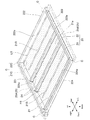
- FIG. 2 is a perspective view of the tray 20 according to the embodiment.
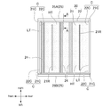
- FIG. 3 is a plan view of the tray 20 according to the embodiment.
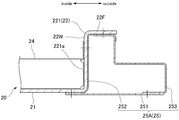
- FIG. 4 is a cross-sectional view taken along the line A in FIG.
- the direction along the traveling direction of the vehicle is referred to as the front-rear direction
- the horizontal direction when viewed in the front-rear direction is referred to as the vehicle width direction
- the vehicle width when viewed in the front-rear direction.
- the direction perpendicular to the direction or the direction of gravity (vertical direction) is called the vertical direction.
- the vehicle body 1 includes a frame 10 constituting the skeleton of the vehicle body 1 and a tray 20 (also referred to as a case or a container) on which a battery 30 such as a lithium ion battery is placed.
- the vehicle body 1 is driven by a battery 30 as a power source, such as an electric vehicle.
- the tray 20 is arranged inside the vehicle from the position of the side member structure 100 (also referred to as a side sill).
- the tray 20 is usually arranged between a pair of side member structures 100 provided on the left and right sides of the vehicle body 1 in the vehicle width direction.
- the tray 20 includes a bottom wall 21 and a peripheral side wall 22 that stands up from the outer periphery of the bottom wall 21.
- the bottom wall 21 is a polygon of a triangle or more in a plan view.
- the bottom wall 21 is a quadrangle in a plan view, as shown in FIG.
- the bottom wall 21 has four corners 21C. Each corner portion 21C of the bottom wall 21 is arranged adjacent to each corner portion 22C of the peripheral side wall 22 which will be described later.
- the bottom wall 21 has a flat plate shape.
- the bottom wall 21 is made of steel, for example.
- the bottom wall 21 has an upper surface 21a arranged along a horizontal plane. In-vehicle parts such as a battery 30 are appropriately placed on the upper surface 21a.
- the bottom wall 21 has rigidity that allows the battery 30 to be placed and supported on the upper surface 21a.
- the upper surface 21a is appropriately formed along the vehicle width direction in order to increase the rigidity of the bottom wall 21 against deformation in the vehicle width direction caused by an impact load from the outside of the vehicle to the inside of the vehicle such as a side collision. May have.
- the reinforcing portion 21R may be a ridge or a groove formed along the vehicle width direction.
- the peripheral side wall 22 has a polygonal shape corresponding to the polygonal shape of the peripheral edge of the bottom wall 21.
- the peripheral side wall 22 when the bottom wall 21 is a quadrangle, the peripheral side wall 22 is a quadrangle.
- the peripheral side wall 22 has a first side wall 221 and a second side wall 222 adjacent to the first side wall 221, a third side wall 223 adjacent to the second side wall 222, and a second side wall 223 adjacent to the third side wall 223. It has four side walls 224 and.
- the fourth side wall 224 is adjacent to the first side wall 221.
- each side wall from the first side wall 221 to the fourth side wall 224 is arranged in a closed ring shape so as to surround the bottom wall 21 from the peripheral edge of the bottom wall 21.
- the number of side walls constituting the peripheral side wall 22 is not limited to four as in the present embodiment, but may be three or more depending on the polygonal shape of the peripheral edge of the bottom wall 21.
- Each side wall of the peripheral side wall 22 has an inner surface facing the center surrounded by the peripheral side wall 22. That is, as shown in FIG. 2, the first side wall 221 has the inner surface 221a of the first side wall. Similarly, the second side wall 222 has the inner surface 222a of the second side wall. The third side wall 223 has an inner surface 223a of the third side wall. The fourth side wall 224 has an inner surface 224a of the fourth side wall.
- the peripheral side wall 22 is perpendicular to the direction in which the peripheral side wall 22 extends, including the peripheral side wall web 22W extending upward from the vehicle outer end portion of the bottom wall 21 and the peripheral side wall flange 22F. It has a cross section.
- the tray 20 including the peripheral side wall 22 can be easily formed from a flat steel plate by press working, but can reasonably secure rigidity capable of resisting a load such as a shearing force and a moment.
- the cross section of the peripheral side wall 22 may be uniform along the peripheral edge of the bottom wall 21.
- the tray 20 includes a high-strength portion HT having a high tensile strength and a low-strength portion LT having a tensile strength lower than that of the high-strength portion HT.
- the high-strength portion HT preferably has a tensile strength of 980 MPa or more, and more preferably 1470 MPa or more.
- the low-strength portion LT has a tensile strength of 270 MPa to 440 MPa.
- the low-strength portion LT has, for example, a tensile strength of 270 MPa, 440 MPa, or 590 MPa.
- the low-strength portion LT has a corner portion 22C on the first side wall inner surface 221a of the first side wall 221 and the second side wall inner surface 222a of the second side wall 222 and the first side wall 22C which are adjacent to each other at inferior angles.
- the low-strength portion LT of the tray 20 has a recessed portion C (first side wall inner surface 221a, second side wall inner surface 222a, and upper surface 21a) in which the corner portion 22C of the peripheral side wall 22 and the corner portion 21C of the bottom wall 21 are adjacent to each other.
- the three surfaces of the above are arranged so as to include adjacent portions).
- the minor angle is the angle of the smaller angle of the angles that share two sides with the apex.
- the high-strength portion HT can mainly share and receive the impact load acting on the tray 20 from the vehicle width direction.
- a recessed portion C that is difficult to press can be formed into a low-strength portion LT. Therefore, the high-strength portion HT can prevent the tray 20 from being plasticized at an early stage and being greatly deformed, and can be made relatively lightweight.
- the low-strength portion LT makes it possible to easily form a box-shaped three-dimensional shape having a recessed portion C by pressing the tray 20 onto a steel plate as a base material. Therefore, a robust and lightweight tray 20 can be provided.
- the tray 20 has a high-strength portion HT in the middle portion in the front-rear direction.
- the high-strength portion HT is formed from the first side wall 221 through the bottom wall 21 to the third side wall 223 facing the first side wall 221.
- the range of the load transmission path when the impact load is applied can be set to the high strength portion HT. Therefore, even if the plate thickness of the tray 20 is reduced, the rigidity in the vehicle width direction can be increased, so that the weight can be reduced efficiently.
- the tray 20 has a low-strength portion LT as a region including a corner portion 21C arranged at two front positions and a recessed portion C having a corner portion 22C corresponding to the corner portion 21C. Further, the tray 20 has a low-strength portion LT as a region including a corner portion 21C arranged at two rear positions and a recessed portion C having a corner portion 22C corresponding to the corner portion 21C. As described above, since the region including the recessed portion C having the corner portion 21C and the corner portion 22C is the low-strength portion LT, the tray 20 can be easily manufactured by pressing the steel plate as the base material.
- the tray 20 is provided with an inner reinforcing member 24 extending from the first side wall 221 to the third side wall 223 facing the first side wall 221 on the bottom wall 21.
- a plurality of inner reinforcing members 24 may be provided. Further, a plurality of inner reinforcing members 24 may be provided side by side in the front-rear direction.
- the impact load applied to one of the first side wall 221 and the third side wall 223 due to a side collision or the like in the vehicle width direction can be dispersed to the plurality of inner reinforcing members 24 and transmitted to the third side wall 223. Therefore, the cross section perpendicular to the longitudinal direction (vehicle width direction) of one inner reinforcing member 24 can be reduced and made compact.
- a single inner reinforcing member 24 may be provided.
- One end of the inner reinforcing member 24 is joined to the inner surface 221a of the first side wall of the first side wall 221 by welding or the like.
- the other end of the inner reinforcing member 24 is joined to the inner surface 223a of the third side wall of the third side wall 223 by welding or the like.
- the inner reinforcing material 24 overlaps with the high-strength portion HT.
- the effect of improving the rigidity of the inner reinforcing material 24 and the effect of improving the rigidity of the high-strength portion HT are combined to effectively increase the rigidity of the range of the load transmission path when an impact load is applied in the vehicle width direction. Can be done. Therefore, the protection performance inside the tray 20 can be improved.
- the first side wall 221 and the third side wall 223 include an outer reinforcing member 25 extending along the first side wall 221 and the third side wall 223.
- the outer reinforcing material 25 usually includes a first outer reinforcing material 25A extending along the first side wall 221 and a second outer reinforcing material 25B extending along the third side wall 223.
- the outer reinforcing material 25 (first outer reinforcing material 25A) has a flexural rigidity and impact energy performance per unit mass with respect to an impact load acting from the outside of the vehicle toward the inside of the vehicle. It has a hollow cross section to ensure. Further, the outer reinforcing member 25 has a plurality of members extending in the front-rear direction, that is, a first member 251 and a second member 252 and a third member 253. The cross section of the outer reinforcing member 25 has a closed annular shape by connecting the first member 251 to the second member 252 and the third member 253 to each other.
- the first member 251 and the second member 252 and the third member 253 are joined to each other by, for example, welding.
- the first member 251 and the second member 252 and the third member 253 are, for example, a flat steel plate or a steel plate bent and formed from a flat steel plate, respectively.
- the outer reinforcing member 25 and the peripheral side wall 22 are joined to each other by welding or the like.
- the outer reinforcing member 25 is not limited to the one formed of three members as in the present embodiment, but may be formed of a single member, may be formed of two members, or may be formed of four or more members. It may be formed from a plurality of members of the above.
- a steel plate to be a high-strength portion HT having a high tensile strength and a steel plate to be a low-strength portion LT having a tensile strength lower than that of the high-strength portion HT are welded (welding step).
- a steel plate having a tensile strength of 1470 MPa is used as the high-strength portion HT.
- a steel plate having a tensile strength of 270 MPa is used as the low-strength portion LT.
- the thickness of the steel plate serving as the high-strength portion HT and the thickness of the steel plate serving as the low-strength portion LT are the same.
- the low-strength portion LT is formed into a corner portion 22C and a corner portion 22C on the first side wall inner surface 221a of the first side wall 221 and the second side wall inner surface 222a of the second side wall 222 which are adjacent to each other at inferior angles.
- the pressing process is performed so as to include a recessed portion C having a corner portion 21C on the upper surface 21a of the bottom wall 21 forming an inferior angle to each of the first side wall inner surface 221a and the second side wall inner surface 222a (molding step).
- the high-strength portion HT is press-processed.
- the tensile strength of the high-strength portion HT or low-strength portion LT after press working can be made higher than the tensile strength of the high-strength portion HT or low-strength portion LT before press working.
- the tray 20 provided with the peripheral side wall 22 erected from the outer periphery of the bottom wall 21 can be easily manufactured. Therefore, it is possible to provide a method for manufacturing a robust and lightweight tray 20.
Landscapes
- Chemical & Material Sciences (AREA)
- Engineering & Computer Science (AREA)
- Chemical Kinetics & Catalysis (AREA)
- General Chemical & Material Sciences (AREA)
- Electrochemistry (AREA)
- Transportation (AREA)
- Mechanical Engineering (AREA)
- Combustion & Propulsion (AREA)
- Aviation & Aerospace Engineering (AREA)
- Containers Having Bodies Formed In One Piece (AREA)
- Body Structure For Vehicles (AREA)
- Battery Mounting, Suspending (AREA)
- Arrangement Or Mounting Of Propulsion Units For Vehicles (AREA)
- Table Equipment (AREA)
Priority Applications (6)
| Application Number | Priority Date | Filing Date | Title |
|---|---|---|---|
| CN202180009501.4A CN114982054B (zh) | 2020-02-04 | 2021-02-04 | 托盘及托盘的制造方法 |
| MX2022008340A MX2022008340A (es) | 2020-02-04 | 2021-02-04 | Bandeja y metodo de fabricacion de bandeja. |
| JP2021575855A JP7518399B2 (ja) | 2020-02-04 | 2021-02-04 | バッテリートレイ及びバッテリートレイの製造方法 |
| US17/783,508 US12240312B2 (en) | 2020-02-04 | 2021-02-04 | Tray and tray manufacturing method |
| KR1020227026279A KR102818157B1 (ko) | 2020-02-04 | 2021-02-04 | 트레이 및 트레이의 제조 방법 |
| EP21750740.9A EP4102628A4 (en) | 2020-02-04 | 2021-02-04 | Tray and tray manufacturing method |
Applications Claiming Priority (2)
| Application Number | Priority Date | Filing Date | Title |
|---|---|---|---|
| JP2020-017224 | 2020-02-04 | ||
| JP2020017224 | 2020-02-04 |
Publications (1)
| Publication Number | Publication Date |
|---|---|
| WO2021157648A1 true WO2021157648A1 (ja) | 2021-08-12 |
Family
ID=77200655
Family Applications (1)
| Application Number | Title | Priority Date | Filing Date |
|---|---|---|---|
| PCT/JP2021/004074 Ceased WO2021157648A1 (ja) | 2020-02-04 | 2021-02-04 | トレイ及びトレイの製造方法 |
Country Status (7)
| Country | Link |
|---|---|
| US (1) | US12240312B2 (https=) |
| EP (1) | EP4102628A4 (https=) |
| JP (1) | JP7518399B2 (https=) |
| KR (1) | KR102818157B1 (https=) |
| CN (1) | CN114982054B (https=) |
| MX (1) | MX2022008340A (https=) |
| WO (1) | WO2021157648A1 (https=) |
Cited By (3)
| Publication number | Priority date | Publication date | Assignee | Title |
|---|---|---|---|---|
| JPWO2022249782A1 (https=) * | 2021-05-24 | 2022-12-01 | ||
| JP2024165327A (ja) * | 2023-05-17 | 2024-11-28 | トヨタ自動車株式会社 | 電池ケースのケース側壁 |
| JP2025505915A (ja) * | 2022-03-14 | 2025-03-05 | ビーワイディー カンパニー リミテッド | 電池トレイ用のサイドビーム、電池トレイ、電池パック及び車両 |
Families Citing this family (2)
| Publication number | Priority date | Publication date | Assignee | Title |
|---|---|---|---|---|
| CN121079832A (zh) | 2023-05-23 | 2025-12-05 | 克利夫兰-克利夫斯钢铁产权公司 | 钢定制焊接的坯件冲压的电池托盘 |
| EP4552881B1 (de) * | 2023-11-13 | 2025-11-05 | Benteler Automobiltechnik GmbH | Batterieträger |
Citations (6)
| Publication number | Priority date | Publication date | Assignee | Title |
|---|---|---|---|---|
| JP2011124101A (ja) | 2009-12-10 | 2011-06-23 | Mitsubishi Motors Corp | バッテリーケース |
| JP2013157242A (ja) * | 2012-01-31 | 2013-08-15 | Mitsubishi Motors Corp | 電池容器 |
| JP2014019203A (ja) * | 2012-07-13 | 2014-02-03 | Mitsubishi Motors Corp | 電池パックトレー |
| CN107732062A (zh) * | 2017-09-29 | 2018-02-23 | 凌云工业股份有限公司 | 一种新能源汽车铝合金电池下壳体及制备方法 |
| CN107732058A (zh) * | 2017-08-29 | 2018-02-23 | 常州普莱德新能源电池科技有限公司 | 电池箱以及制造方法 |
| JP2020017224A (ja) | 2018-07-27 | 2020-01-30 | 株式会社寺岡精工 | 商品販売データ処理装置、プログラム、及び販売数量の入力方法 |
Family Cites Families (7)
| Publication number | Priority date | Publication date | Assignee | Title |
|---|---|---|---|---|
| CN201777300U (zh) * | 2010-07-30 | 2011-03-30 | 比亚迪股份有限公司 | 车辆底部构造 |
| JP5552109B2 (ja) | 2011-12-27 | 2014-07-16 | 株式会社神戸製鋼所 | 車載用バッテリートレイおよび車載用バッテリーフレーム |
| JP6589090B2 (ja) * | 2014-11-26 | 2019-10-16 | 三菱自動車工業株式会社 | 電池パックの補強構造 |
| CN110383526A (zh) * | 2017-01-04 | 2019-10-25 | 形状集团 | 节点模块化的车辆电池托盘结构 |
| CN109216603A (zh) * | 2017-06-30 | 2019-01-15 | 比亚迪股份有限公司 | 电池托盘、电池包总成以及具有它的车辆 |
| WO2019198753A1 (ja) * | 2018-04-11 | 2019-10-17 | 本田技研工業株式会社 | 自動車の車体構造 |
| CN209843772U (zh) * | 2019-04-24 | 2019-12-24 | 浙江吉利控股集团有限公司 | 一种电池托盘 |
-
2021
- 2021-02-04 KR KR1020227026279A patent/KR102818157B1/ko active Active
- 2021-02-04 JP JP2021575855A patent/JP7518399B2/ja active Active
- 2021-02-04 US US17/783,508 patent/US12240312B2/en active Active
- 2021-02-04 WO PCT/JP2021/004074 patent/WO2021157648A1/ja not_active Ceased
- 2021-02-04 EP EP21750740.9A patent/EP4102628A4/en active Pending
- 2021-02-04 CN CN202180009501.4A patent/CN114982054B/zh active Active
- 2021-02-04 MX MX2022008340A patent/MX2022008340A/es unknown
Patent Citations (6)
| Publication number | Priority date | Publication date | Assignee | Title |
|---|---|---|---|---|
| JP2011124101A (ja) | 2009-12-10 | 2011-06-23 | Mitsubishi Motors Corp | バッテリーケース |
| JP2013157242A (ja) * | 2012-01-31 | 2013-08-15 | Mitsubishi Motors Corp | 電池容器 |
| JP2014019203A (ja) * | 2012-07-13 | 2014-02-03 | Mitsubishi Motors Corp | 電池パックトレー |
| CN107732058A (zh) * | 2017-08-29 | 2018-02-23 | 常州普莱德新能源电池科技有限公司 | 电池箱以及制造方法 |
| CN107732062A (zh) * | 2017-09-29 | 2018-02-23 | 凌云工业股份有限公司 | 一种新能源汽车铝合金电池下壳体及制备方法 |
| JP2020017224A (ja) | 2018-07-27 | 2020-01-30 | 株式会社寺岡精工 | 商品販売データ処理装置、プログラム、及び販売数量の入力方法 |
Cited By (7)
| Publication number | Priority date | Publication date | Assignee | Title |
|---|---|---|---|---|
| JPWO2022249782A1 (https=) * | 2021-05-24 | 2022-12-01 | ||
| WO2022249782A1 (ja) * | 2021-05-24 | 2022-12-01 | 株式会社ジーテクト | バッテリーケース構造およびバッテリーケース構造の製造方法 |
| JP7526364B2 (ja) | 2021-05-24 | 2024-07-31 | 株式会社ジーテクト | バッテリーケース構造およびバッテリーケース構造の製造方法 |
| JP2025505915A (ja) * | 2022-03-14 | 2025-03-05 | ビーワイディー カンパニー リミテッド | 電池トレイ用のサイドビーム、電池トレイ、電池パック及び車両 |
| JP7821287B2 (ja) | 2022-03-14 | 2026-02-26 | ビーワイディー カンパニー リミテッド | 電池トレイ用のサイドビーム、電池トレイ、電池パック及び車両 |
| JP2024165327A (ja) * | 2023-05-17 | 2024-11-28 | トヨタ自動車株式会社 | 電池ケースのケース側壁 |
| JP7831396B2 (ja) | 2023-05-17 | 2026-03-17 | トヨタ自動車株式会社 | 電池ケースのケース側壁 |
Also Published As
| Publication number | Publication date |
|---|---|
| CN114982054B (zh) | 2025-03-21 |
| JP7518399B2 (ja) | 2024-07-18 |
| KR20220122726A (ko) | 2022-09-02 |
| EP4102628A4 (en) | 2023-08-02 |
| US20220388386A1 (en) | 2022-12-08 |
| CN114982054A (zh) | 2022-08-30 |
| JPWO2021157648A1 (https=) | 2021-08-12 |
| US12240312B2 (en) | 2025-03-04 |
| MX2022008340A (es) | 2022-08-04 |
| EP4102628A1 (en) | 2022-12-14 |
| KR102818157B1 (ko) | 2025-06-10 |
Similar Documents
| Publication | Publication Date | Title |
|---|---|---|
| WO2021157648A1 (ja) | トレイ及びトレイの製造方法 | |
| EP3052333B1 (en) | Vehicle body frame and vehicle underfloor structure | |
| JP6859933B2 (ja) | 車両用電池ケース及びその製造方法 | |
| JP6566176B1 (ja) | ロッカー部材および車両 | |
| JP5549964B2 (ja) | 耐衝突性能に優れた車両用骨格部材構造 | |
| JP7190568B2 (ja) | 電池ケース | |
| US11208150B2 (en) | Automotive frame member and electric vehicle | |
| EP4253114B1 (en) | Automotive battery case and method for manufacturing same | |
| JP2019127163A (ja) | 車体構造 | |
| JP4733762B2 (ja) | 車体側部構造 | |
| KR102098495B1 (ko) | 배터리 케이스 | |
| CN113879238B (zh) | 车辆的前部车身结构 | |
| KR102820951B1 (ko) | 전기 자동차용 배터리팩 하부케이스 | |
| JP7264597B2 (ja) | 車両用構造部材及び車両 | |
| KR102335754B1 (ko) | 차량용 구조 부품 | |
| JP2018176964A (ja) | 自動車車両 | |
| CN207644329U (zh) | 一种汽车防撞梁结构及汽车 | |
| JP2021172117A (ja) | 自動車骨格部材および電気自動車 | |
| JP2020147124A (ja) | 車体部材、および、車体構造 | |
| JP6613478B2 (ja) | 車両の衝撃吸収部材 | |
| CN221340803U (zh) | 车身结构以及车辆 | |
| US20250388268A1 (en) | Vehicle base structure | |
| JP2023182437A (ja) | 車両 |
Legal Events
| Date | Code | Title | Description |
|---|---|---|---|
| 121 | Ep: the epo has been informed by wipo that ep was designated in this application |
Ref document number: 21750740 Country of ref document: EP Kind code of ref document: A1 |
|
| ENP | Entry into the national phase |
Ref document number: 2021575855 Country of ref document: JP Kind code of ref document: A |
|
| WWE | Wipo information: entry into national phase |
Ref document number: MX/A/2022/008340 Country of ref document: MX |
|
| ENP | Entry into the national phase |
Ref document number: 20227026279 Country of ref document: KR Kind code of ref document: A |
|
| NENP | Non-entry into the national phase |
Ref country code: DE |
|
| ENP | Entry into the national phase |
Ref document number: 2021750740 Country of ref document: EP Effective date: 20220905 |
|
| WWP | Wipo information: published in national office |
Ref document number: MX/A/2022/008340 Country of ref document: MX |
|
| WWG | Wipo information: grant in national office |
Ref document number: 17783508 Country of ref document: US |
|
| WWG | Wipo information: grant in national office |
Ref document number: 202180009501.4 Country of ref document: CN |
|
| WWG | Wipo information: grant in national office |
Ref document number: MX/A/2022/008340 Country of ref document: MX |