WO2021157064A1 - 表示制御装置、表示システム、及び表示制御方法 - Google Patents
表示制御装置、表示システム、及び表示制御方法 Download PDFInfo
- Publication number
- WO2021157064A1 WO2021157064A1 PCT/JP2020/004868 JP2020004868W WO2021157064A1 WO 2021157064 A1 WO2021157064 A1 WO 2021157064A1 JP 2020004868 W JP2020004868 W JP 2020004868W WO 2021157064 A1 WO2021157064 A1 WO 2021157064A1
- Authority
- WO
- WIPO (PCT)
- Prior art keywords
- display
- display area
- brightness
- backlight
- instruction
- Prior art date
- Legal status (The legal status is an assumption and is not a legal conclusion. Google has not performed a legal analysis and makes no representation as to the accuracy of the status listed.)
- Ceased
Links
Images





Classifications
-
- G—PHYSICS
- G09—EDUCATION; CRYPTOGRAPHY; DISPLAY; ADVERTISING; SEALS
- G09G—ARRANGEMENTS OR CIRCUITS FOR CONTROL OF INDICATING DEVICES USING STATIC MEANS TO PRESENT VARIABLE INFORMATION
- G09G3/00—Control arrangements or circuits, of interest only in connection with visual indicators other than cathode-ray tubes
- G09G3/20—Control arrangements or circuits, of interest only in connection with visual indicators other than cathode-ray tubes for presentation of an assembly of a number of characters, e.g. a page, by composing the assembly by combination of individual elements arranged in a matrix no fixed position being assigned to or needed to be assigned to the individual characters or partial characters
-
- G—PHYSICS
- G09—EDUCATION; CRYPTOGRAPHY; DISPLAY; ADVERTISING; SEALS
- G09G—ARRANGEMENTS OR CIRCUITS FOR CONTROL OF INDICATING DEVICES USING STATIC MEANS TO PRESENT VARIABLE INFORMATION
- G09G3/00—Control arrangements or circuits, of interest only in connection with visual indicators other than cathode-ray tubes
- G09G3/20—Control arrangements or circuits, of interest only in connection with visual indicators other than cathode-ray tubes for presentation of an assembly of a number of characters, e.g. a page, by composing the assembly by combination of individual elements arranged in a matrix no fixed position being assigned to or needed to be assigned to the individual characters or partial characters
- G09G3/34—Control arrangements or circuits, of interest only in connection with visual indicators other than cathode-ray tubes for presentation of an assembly of a number of characters, e.g. a page, by composing the assembly by combination of individual elements arranged in a matrix no fixed position being assigned to or needed to be assigned to the individual characters or partial characters by control of light from an independent source
-
- G—PHYSICS
- G09—EDUCATION; CRYPTOGRAPHY; DISPLAY; ADVERTISING; SEALS
- G09G—ARRANGEMENTS OR CIRCUITS FOR CONTROL OF INDICATING DEVICES USING STATIC MEANS TO PRESENT VARIABLE INFORMATION
- G09G3/00—Control arrangements or circuits, of interest only in connection with visual indicators other than cathode-ray tubes
- G09G3/20—Control arrangements or circuits, of interest only in connection with visual indicators other than cathode-ray tubes for presentation of an assembly of a number of characters, e.g. a page, by composing the assembly by combination of individual elements arranged in a matrix no fixed position being assigned to or needed to be assigned to the individual characters or partial characters
- G09G3/34—Control arrangements or circuits, of interest only in connection with visual indicators other than cathode-ray tubes for presentation of an assembly of a number of characters, e.g. a page, by composing the assembly by combination of individual elements arranged in a matrix no fixed position being assigned to or needed to be assigned to the individual characters or partial characters by control of light from an independent source
- G09G3/36—Control arrangements or circuits, of interest only in connection with visual indicators other than cathode-ray tubes for presentation of an assembly of a number of characters, e.g. a page, by composing the assembly by combination of individual elements arranged in a matrix no fixed position being assigned to or needed to be assigned to the individual characters or partial characters by control of light from an independent source using liquid crystals
Definitions
- the present invention relates to a display control device, a display system, and a display control method.
- a display device having a plurality of display areas is known.
- the display control device that controls this display device displays information whose importance changes according to the situation in each display area, and further emphasizes the display area for displaying the information of high importance to the user. I was trying to draw attention to high-quality information.
- the display control device described in Patent Document 1 causes the display area to emit light by emitting light from a lighting unit provided in the display area, or by adjusting the brightness, saturation, or hue of the display area.
- the information that is of high importance to be displayed was emphasized to improve visibility.
- the present invention has been made to solve the above problems, and an object of the present invention is to provide a display control device that realizes low power consumption in a display device and improves visibility.
- the display control device includes a display screen divided into a plurality of display areas, a backlight capable of emitting light with different brightness for each display area, and a backlight for adjusting the brightness of the backlight for each display area.
- a display control device that controls a display device that has a power supply, and adjusts the brightness of the image data displayed on the display screen for each display area, and the brightness of the backlight for each display area. It is provided with a control unit that outputs an instruction to a backlight power supply and outputs an instruction to adjust the brightness of image data for each display area to a drawing adjustment unit.
- a display control device that realizes low power consumption and improves visibility in the display device is provided. can.
- FIG. It is a block diagram which shows the structural example of the display system which concerns on Embodiment 1.
- FIG. It is a flowchart which shows the operation example of the display control apparatus which concerns on Embodiment 1.
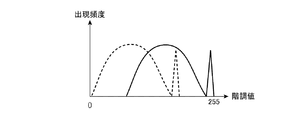
- FIG. It is a graph which shows an example of the histogram which shows the distribution of the gradation value of image data. It is a graph which shows another example of the histogram which shows the distribution of the gradation value of the image data.
- FIG. 1 It is a figure which shows an example of the line-of-sight toward a display device which has a large display screen which covers the whole dashboard. It is a figure which shows an example of the external light irradiation area in the display device which has a large display screen which covers the whole dashboard. It is a figure which shows an example of the display area in the display device which has a large display screen which covers the whole dashboard. It is a figure which shows an example of the hardware composition of the display control device which concerns on Embodiment 1. FIG. It is a figure which shows another example of the hardware composition of the display control device which concerns on Embodiment 1. FIG.
- FIG. 1 is a block diagram showing a configuration example of the display system 30 according to the first embodiment.
- the display system 30 includes a display control device 10 and a display device 20.
- the display system 30 is a meter cluster panel installed on the entire dashboard of the vehicle or on the driver's seat side, or a center display installed between the driver's seat and the passenger seat of the dashboard.
- the display device 20 includes a display screen 21, a backlight 22, and a backlight power supply 23.
- the display screen 21 is composed of a liquid crystal panel or the like.
- the display screen 21 is divided into a plurality of areas, and the backlight 22 arranged on the back surface of the display screen 21 can emit light with different brightness for each area.
- the area is represented by a square frame, and a light source such as an LED (Light Emitting Diode) is arranged for each area, and the brightness can be adjusted for each area.
- the shape of the area is not limited to the square frame.
- the backlight power supply 23 adjusts the brightness of the backlight 22 for each area of the display screen 21. In the first embodiment, it is assumed that one or more areas are aggregated to form one display area. Further, one content is displayed in one display area.
- the line-of-sight detection unit 1, the operation detection unit 2, the external light detection unit 3, and the temperature detection unit 4 are connected to the display control device 10.
- the line-of-sight detection unit 1 detects the user's line of sight and outputs the detection result as line-of-sight information.
- the line-of-sight detection unit 1 is composed of, for example, a camera that captures an image of the user and an image processing device that detects the user's line of sight from the camera image.
- the user is, for example, a driver.
- the operation detection unit 2 detects the display area that the user is trying to operate or the display area that is being operated, and outputs the detection result as operation information.
- the operation detection unit 2 is composed of, for example, a camera that captures an image of the user and an image processing device that detects a display area in which a user's finger or the like exists from the camera image. Further, for example, the operation detection unit 2 is a proximity sensor that detects the approach and contact of a user's finger or the like. Further, for example, the operation detection unit 2 is a touch panel that is integrally configured with the display screen 21 and detects the approach and contact of a user's finger or the like.
- the external light detection unit 3 detects a display area illuminated by external light such as the sun, and outputs the detection result as external light information.
- the external light detection unit 3 is, for example, a plurality of illuminance sensors installed around the display screen 21, installed on the back surface of the display screen 21, or built in the pixels of the display screen 21. Further, for example, the external light detection unit 3 is composed of a GPS (Global Positioning System) sensor that detects the position of the vehicle at the current date and time, a gyro sensor that detects the direction and inclination of the vehicle, and an arithmetic unit.
- GPS Global Positioning System
- This arithmetic unit calculates the position of the sun at the current date and time based on the position of the vehicle, and on the display screen 21 based on the calculated position of the sun, the direction and inclination of the vehicle, the position of the window of the vehicle, and the like. Estimate the area illuminated by the sunlight.
- the temperature detection unit 4 detects the temperature of the display screen 21 and outputs the detection result as temperature information.
- the temperature detection unit 4 is, for example, a temperature sensor installed in the backlight 22.
- the display control device 10 includes a line-of-sight information acquisition unit 11, an operation information acquisition unit 12, an external light information acquisition unit 13, a temperature information acquisition unit 14, a drawing adjustment unit 15, and a control unit 16.
- the line-of-sight information acquisition unit 11 acquires the line-of-sight information from the line-of-sight detection unit 1 and outputs it to the control unit 16.
- the operation information acquisition unit 12 acquires the operation information from the operation detection unit 2 and outputs it to the control unit 16.
- the external light information acquisition unit 13 acquires external light information from the external light detection unit 3 and outputs it to the control unit 16.
- the temperature information acquisition unit 14 acquires temperature information from the temperature detection unit 4 and outputs it to the control unit 16.
- the display control device 10 may be configured to acquire information from all of the line-of-sight detection unit 1, the operation detection unit 2, the external light detection unit 3, and the temperature detection unit 4, or the line-of-sight detection unit 1, the operation. Information may be acquired from at least one of the detection unit 2, the external light detection unit 3, and the temperature detection unit 4.
- the image data to be displayed on the display screen 21 is input to the drawing adjustment unit 15 and the control unit 16 of the display control device 10.
- the image data includes a meter image showing information necessary for driving such as the speed of the vehicle, an image outside the vehicle captured by a camera installed in the vehicle, and a control screen of an air conditioner (hereinafter referred to as "air conditioner") mounted on the vehicle.
- air conditioner an air conditioner
- the control screen of the audio device mounted on the vehicle the route guidance screen of the navigation device mounted on the vehicle, and the like.
- the meter image is one content
- the image outside the vehicle is also one content.
- the drawing adjustment unit 15 adjusts the brightness of the image data displayed on the display screen 21 for each display area according to the instruction of the control unit 16.
- the drawing adjustment unit 15 adjusts the brightness of the image data by adjusting the gradation value, tone curve, contrast, etc. of the image data.
- the drawing adjustment unit 15 outputs the adjusted image data to the display screen 21.
- the control unit 16 uses the information and image data acquired by at least one of the line-of-sight information acquisition unit 11, the operation information acquisition unit 12, the external light information acquisition unit 13, and the temperature information acquisition unit 14 to display the display screen 21.
- An instruction for adjusting the brightness of the backlight 22 for each display area is output to the backlight power supply 23, and an instruction for adjusting the brightness of the image data for each display area is output to the drawing adjustment unit 15.
- FIG. 2 is a flowchart showing an operation example of the display control device 10 according to the first embodiment.
- the display control device 10 starts the operation shown in the flowchart of FIG. 2, and repeats the operation shown in the flowchart of FIG. 2 until the display device 20 stops the operation.
- step ST1 the control unit 16 determines whether or not the temperature of the display screen 21 is equal to or higher than a predetermined threshold value by using the temperature information acquired by the temperature information acquisition unit 14.
- the control unit 16 performs the operation of step ST2.
- the control unit 16 performs the operation of step ST11.
- This threshold value is a temperature (for example, ⁇ 20 ° C.) that interferes with the moving image responsiveness of the display screen 21.
- step ST11 the control unit 16 performs temperature priority control in order to improve the moving image responsiveness of the display screen 21 at low temperature.
- the control unit 16 outputs an instruction to raise the brightness of the backlight 22 as much as possible to the backlight power supply 23 in order to raise the temperature of the display screen 21. Further, the control unit 16 does not change the brightness of the display screen 21 even if the backlight 22 is brightened, and even if the image data is partially overexposed or underexposed, there is no problem in visibility as a whole.
- An instruction to reduce the brightness of the image data is output to the drawing adjustment unit 15. According to the instruction of the control unit 16, the backlight power supply 23 raises the brightness of the backlight 22, and the drawing adjustment unit 15 lowers the brightness of the image data, so that the moving image responsiveness of the display screen 21 is improved.
- FIG. 3 is a graph showing an example of a histogram showing the distribution of gradation values of image data.
- the horizontal axis of the graph is the gradation value of each pixel of the image data
- the vertical axis of the graph is the appearance frequency of the gradation value.
- the drawing adjustment unit 15 darkens the image data by adjusting to the gradation value shown by the broken line in the temperature priority control.
- the gradation value on the horizontal axis of FIG. 3 is "255" because it is assumed that the display system 30 handles 8-bit data, and the display system 30 has 10-bit or 12-bit data or the like. It does not matter if it is configured to handle.
- each gradation value is represented by translation of the gradation value, but in reality, it is necessary to adjust in consideration of the gain. That is, the drawing adjustment unit 15 adjusts each gradation value to be 1/2 times if the brightness of the backlight 22 is twice the normal brightness, and the brightness of the backlight 22 is 1/2 times the normal brightness. If there is, adjust so that each gradation value is doubled. Further, it is desirable that the drawing adjustment unit 15 also considers correction by a gamma curve (tone curve).
- step ST2 the control unit 16 determines whether or not the user is looking at the display screen 21 by using the line-of-sight information acquired by the line-of-sight information acquisition unit 11.
- step ST2 “YES” the control unit 16 performs the operation of step ST3.
- step ST2 “NO” the control unit 16 performs the operation of step ST12.
- step ST12 the control unit 16 performs power priority control in order to suppress the power consumption of the backlight 22.
- the control unit 16 outputs an instruction to reduce the brightness of the backlight 22 as much as possible to the backlight power supply 23. Further, the control unit 16 outputs an instruction to increase the brightness of the image data to the drawing adjustment unit 15 so that the brightness of the display screen 21 does not change even if the backlight 22 is darkened. Since the user is not looking at the display screen 21 during the power priority control, the control unit 16 raises the brightness of the image data even if the image quality of the image data is lowered. According to the instruction of the control unit 16, the backlight power supply 23 lowers the brightness of the backlight 22, and the drawing adjustment unit 15 raises the brightness of the image data, so that the power consumption of the backlight 22 is suppressed.
- FIG. 4 is a graph showing another example of a histogram showing the distribution of gradation values of image data.
- the horizontal axis of the graph is the gradation value of each pixel of the image data
- the vertical axis of the graph is the appearance frequency of the gradation value.
- the gradation value on the horizontal axis of FIG. 4 is "255" because it is assumed that the display system 30 handles 8-bit data, and the display system 30 has 10-bit or 12-bit data or the like. It does not matter if it is configured to handle.
- an example of adjusting each gradation value is represented by translation of the gradation value, but in reality, it is necessary to adjust in consideration of the gain. That is, the drawing adjustment unit 15 adjusts each gradation value to be 1/2 times if the brightness of the backlight 22 is twice the normal brightness, and the brightness of the backlight 22 is 1/2 times the normal brightness. If there is, adjust so that each gradation value is doubled. Further, it is desirable that the drawing adjustment unit 15 also considers correction by a gamma curve (tone curve).
- step ST3 the control unit 16 determines whether or not the user intends to operate the display screen 21 or whether or not the user is operating the display screen 21 by using the operation information acquired by the operation information acquisition unit 12.
- the case where the user is trying to operate the display screen 21 is a case where the user's finger or the like is approaching the display screen 21.
- the case where the user is operating the display screen 21 is a case where the user's finger or the like is in contact with the display screen 21.
- step ST3 “YES” the control unit 16 performs the operation of step ST5.
- step ST3 “NO” the control unit 16 performs the operation of step ST4.
- step ST4 the control unit 16 determines whether or not the display screen 21 is irradiated with external light by using the external light information acquired by the external light information acquisition unit 13.
- step ST4 “YES” the control unit 16 performs the operation of step ST14.
- step ST4 “NO” the control unit 16 performs the operation of step ST13.
- the external light detection unit 3 is a plurality of illuminance sensors, for example, the control unit 16 determines that the external light is irradiating the periphery of the illuminance sensor whose illuminance is equal to or higher than a predetermined threshold value.
- step ST13 the control unit 16 performs image quality priority control in order to improve operability.
- the control unit 16 outputs an instruction to lower the brightness of the backlight 22 to the backlight power supply 23 so that the power consumption of the backlight 22 can be suppressed to some extent. Further, the control unit 16 does not change the brightness of the display screen 21 even if the backlight 22 is darkened, and even if the image data is partially overexposed or underexposed, there is no problem in visibility as a whole.
- An instruction to increase the brightness of the image data is output to the drawing adjustment unit 15. According to the instruction of the control unit 16, the backlight power supply 23 lowers the brightness of the backlight 22, and the drawing adjustment unit 15 raises the brightness of the image data, so that the image quality of the image data is improved.
- the drawing adjustment unit 15 brightens the image data by adjusting the gradation value on the lower side indicated by the solid line to the gradation value indicated by the alternate long and short dash line.
- the gradation value after adjustment indicated by the alternate long and short dash line does not come too close to the gradation value near the unadjusted "255", so that the gradation property is not impaired (that is, the image quality is not deteriorated). ).
- step ST14 the control unit 16 performs visibility priority control so that the user can visually recognize the image data even when it is irradiated with external light.
- the control unit 16 outputs an instruction to maximize the brightness of the backlight 22 to the backlight power supply 23. Further, the control unit 16 outputs an instruction to increase the contrast of the image data to the drawing adjustment unit 15 even if the image quality is lowered.
- the backlight power supply 23 raises the brightness of the backlight 22
- the drawing adjustment unit 15 raises the contrast of the image data, so that the visibility of the image data is improved.
- control in steps ST11 to ST14 was the control for the entire display screen 21, whereas the control in steps ST15 to ST17 is the control for each display area of the display screen 21. Since one content is displayed in one display area, it can be said that the control in steps ST15 to ST17 is the control for each content. Although the control for each display area is illustrated here, the control may be for each area constituting the display area.
- step ST5 the control unit 16 uses the operation information acquired by the operation information acquisition unit 12 to determine whether or not the display area of the display screen 21 is the display area that the user intends to operate or is operating. judge.
- the control unit 16 performs the operation of step ST6 with respect to the display area to be operated by the user or the display area being operated (step ST5 “YES”).
- the control unit 16 performs the operation of step ST15 with respect to the display area that the user is not trying to operate and the display area that is not being operated (step ST5 “NO”).
- step ST15 the control unit 16 performs the same power priority control as in step ST12 for the display area that the user is not trying to operate and the display area that is not being operated.
- step ST6 the control unit 16 uses the external light information acquired by the external light information acquisition unit 13 to determine whether or not the display area to be operated by the user is irradiated with external light. judge.
- step ST6 “YES” the control unit 16 performs the operation of step ST17.
- step ST6 “NO” the control unit 16 performs the operation of step ST16.
- step ST16 the control unit 16 performs the same image quality priority control as in step ST13 for the display area that the user is trying to operate or is operating and is not irradiated with external light.
- step ST17 the control unit 16 performs the same visibility priority control as in step ST14 for the display area that the user is trying to operate or is operating and is illuminated by external light.
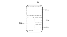
- FIG. 5 is a diagram showing a division example of the display areas 21a to 21d.
- the display device 20 having the display screen 21 shown in FIG. 5 is a center display, and the display screen 21 is divided into four display areas 21a to 21d.
- the display area 21a is an area for displaying the route guidance screen of the navigation device.
- the display area 21b is a screen for displaying a meter image.
- the display area 21c is an area for displaying the control screen of the air conditioner.
- the display area 21d is an area for displaying the control screen of the audio device.
- FIG. 6 is a diagram showing an example of control for the display areas 21a to 21d.
- the user operates the control screen of the audio device displayed in the display area 21d while looking at the display screen 21. Further, the display screen 21 is not irradiated with external light. Therefore, the display control device 10 performs image quality priority control (step ST16) for the display area 21d.
- the display areas 21a to 21c are display areas that are not operated by the user. Therefore, the display control device 10 performs power priority control (step ST15) for the display areas 21a to 21c.
- FIG. 7 is a diagram showing another example of control over the display areas 21a to 21d.
- the user who was operating the control screen of the audio device displayed in the display area 21d while the display screen 21 was not irradiated with external light then visited the route guidance screen of the navigation screen displayed in the display area 21a. I'm trying to operate.
- the display control device 10 performs image quality priority control (step ST16) for the display area 21a. Further, the display control device 10 performs power priority control (step ST15) for the display areas 21b to 21d.
- the display control device 10 performs image quality priority control only on the display area 21a to 21d that the user intends to operate or is operating, and performs power priority control on the other display areas. As a result, the power consumption of the backlight 22 is suppressed.
- each display area may be freely arranged by a user, a device for generating image data, or the like.
- the display control device 10 needs to obtain information related to the arrangement of each display area.
- a method of obtaining there are methods (1) to (3).
- the display control device 10 obtains information related to the arrangement of each display area from the device side that generates image data in a format such as mapping data of each display area, in addition to the image data.
- the display control device 10 When the arrangement of each display area is not completely free arrangement and the user or the like selects an arrangement pattern from a plurality of arrangement patterns prepared in advance, the display control device 10 generates image data. A method of obtaining information on the selected arrangement pattern from the device side.
- the display control device 10 includes a drawing adjustment unit 15 and a control unit 16.
- the drawing adjustment unit 15 adjusts the brightness of the image data displayed on the display screen 21 for each display area.
- the control unit 16 outputs an instruction for adjusting the brightness of the backlight 22 for each display area to the backlight power supply 23, and outputs an instruction for adjusting the brightness of the image data for each display area to the drawing adjustment unit 15. .
- the display control device 10 can switch between the control of suppressing the power consumption of the backlight 22 and the control of improving the visibility of the image data for each display area according to the state of each display area. .. Therefore, it is possible to realize low power consumption and improve visibility in the display device 20.
- the display control device 10 includes an operation information acquisition unit 12 that acquires operation information indicating a display area that the user is trying to operate or is operating.
- the control unit 16 uses the operation information acquired by the operation information acquisition unit 12 to give an instruction to change the brightness of the backlight 22 between the display area that the user is trying to operate or is operating and the other area.
- an instruction to change the brightness of the image data between the display area to be operated or operated by the user and the other area is output to the drawing adjustment unit 15.
- the display control device 10 performs image quality priority control or visibility priority control only in the display area that the user intends to operate or is operating, and image quality priority control or visibility priority control in the other display areas. It is possible to perform power priority control with lower power consumption than. Therefore, the display control device 10 can realize low power consumption and improve visibility in the display device 20.
- the display control device 10 includes an external light information acquisition unit 13 that acquires external light information indicating a display area illuminated by external light.
- the control unit 16 uses the external light information acquired by the external light information acquisition unit 13 to give an instruction to change the brightness of the backlight 22 between the display area illuminated by the external light and the other display areas.
- an instruction to change the brightness of the image data in the display area illuminated by external light and the other display areas is output to the drawing adjustment unit 15.
- the display control device 10 performs visibility priority control only in the display area illuminated by external light, and performs image quality priority control in the other display areas, which consumes less power than the visibility priority control. be able to. Therefore, the display control device 10 can realize low power consumption and improve visibility in the display device 20.
- the display control device 10 includes a temperature information acquisition unit 14 that acquires temperature information indicating the temperature of the display screen 21. Using the temperature information acquired by the temperature information acquisition unit 14, the control unit 16 outputs an instruction to brighten the backlight 22 to the backlight power supply 23 and backs up when the temperature of the display screen 21 is less than the threshold value. An instruction to darken the image data is output to the drawing adjustment unit 15 so that the brightness of the display screen 21 does not change even if the light 22 is brightened. As a result, the display control device 10 can improve the moving image responsiveness of the display device 20.
- the control unit 16 uses the line-of-sight information acquired by the line-of-sight information acquisition unit 11 to give an instruction to change the brightness of the backlight 22 between the display area viewed by the user and the other display areas. In addition to outputting to 23, an instruction to change the brightness of the image data between the display area viewed by the user and the other display area may be output to the drawing adjustment unit 15.
- FIG. 8 is a diagram showing an example of lines of sight 31a and 32a facing the display device 20 having a large display screen 21 that covers the entire dashboard.
- display areas 21e and 21f are shown among a plurality of display areas in which the display screen 21 is divided.
- FIG. 8 shows an example in which there are two users.
- the line-of-sight information acquisition unit 11 obtains line-of-sight information indicating the line-of-sight 31a of the user 31 sitting in the driver's seat in front of the steering wheel 33 and line-of-sight information indicating the line-of-sight 32a of the user 32 sitting in the passenger seat from the line-of-sight detection unit 1. get.
- control unit 16 performs image quality priority control on the display area 21e viewed by the user 31 and the display area 21f viewed by the user 32, and performs power priority control on the display area not viewed by the users 31 and 32. ..
- the display control device 10 performs image quality priority control only on the display areas 21e and 21f viewed by the users 31 and 32, and power priority control that consumes less power than the image quality priority control for the other display areas.
- FIG. 9 is a diagram showing an example of an external light irradiation region 40 in a display device 20 having a large display screen 21 that covers the entire dashboard.
- the display areas 21g and 21h are shown among the plurality of display areas in which the display screen 21 is divided.
- the external light information acquisition unit 13 acquires external light information indicating that the external light irradiation region 40 extends over the display areas 21g and 21h from the external light detection unit 3.
- the control unit 16 uses this external light information, the control unit 16 performs visibility priority control for the display areas 21g and 21h irradiated by the external light, and consumes more power in the other display areas than in the visibility priority control. Perform low image quality priority control or power priority control. In this way, the display control device 10 performs visibility priority control only in the display areas 21g and 21h illuminated by external light, and controls the other display areas with lower power consumption than the visibility priority control. By doing so, it is possible to realize low power consumption and improve visibility in the display device 20.
- FIG. 10 is a diagram showing an example of display areas 21i to 21l in a display device 20 having a large display screen 21 that covers the entire dashboard.
- display areas 21i, 21j, 21k, and 21l are shown among a plurality of display areas in which the display screen 21 is divided.
- the display area 21i displays a camera image on the left rear side of the vehicle.
- the display area 21j displays a camera image on the right rear side of the vehicle.
- the display area 21k displays a meter image.
- the display area 21l which is a display area other than the display areas 21i, 21j, and 21k of the display screen 21, displays a screen of an air conditioner, an audio device, a navigation device, or the like.
- the camera image of the display areas 21i and 21j and the meter image of the display area 21k are contents that are required to have higher moving image responsiveness than the screen of the air conditioner, the audio device, the navigation device, or the like in the display area 21l.
- the temperature information acquisition unit 14 acquires temperature information indicating that the temperature of the display screen 21 is less than the threshold value from the temperature detection unit 4.
- the control unit 16 uses this temperature information to perform temperature priority control for the display areas 21i, 21j, and 21k, which are required to have high moving image responsiveness, and controls the display area 21l with lower power consumption than the temperature priority control. conduct.
- the display control device 10 performs temperature priority control only in the display areas 21i, 21j, and 21k having low temperature and high importance, and consumes less power in the other display areas 21l as compared with the temperature priority control. By performing low control, it is possible to realize low power consumption and improve visibility in the display device 20.
- the display system 30 of the first embodiment includes one display device 20, and the display screen 21 is divided into a plurality of display areas.
- the display system 30 includes a plurality of display devices 20. May be good.
- the display control device 10 may control one display device 20 as one display area for each display device 20, or divide each of the plurality of display devices 20 into a plurality of display areas and a plurality of display devices 20. All the display areas of the display device 20 may be controlled for each display area.
- 11 and 12 are diagrams showing a hardware configuration example of the display control device 10 according to the first embodiment.
- the functions of the line-of-sight information acquisition unit 11, the operation information acquisition unit 12, the external light information acquisition unit 13, the temperature information acquisition unit 14, the drawing adjustment unit 15, and the control unit 16 in the display control device 10 are realized by the processing circuit. That is, the display control device 10 includes a processing circuit for realizing the above functions.
- the processing circuit may be a processing circuit 100 as dedicated hardware, or a processor 101 that executes a program stored in the memory 102.
- the processing circuit 100 may be, for example, a single circuit, a composite circuit, a programmed processor, a parallel programmed processor, or an ASIC (Application Specific Integrated Circuit). ), FPGA (Field Processor Gate Array), or a combination thereof.
- the functions of the line-of-sight information acquisition unit 11, the operation information acquisition unit 12, the external light information acquisition unit 13, the temperature information acquisition unit 14, the drawing adjustment unit 15, and the control unit 16 may be realized by a plurality of processing circuits 100. The functions of each part may be collectively realized by one processing circuit 100.
- the processing circuit is the processor 101, the line-of-sight information acquisition unit 11, the operation information acquisition unit 12, the external light information acquisition unit 13, the temperature information acquisition unit 14, the drawing adjustment unit 15, and the control unit.
- the 16 functions are realized by software, firmware, or a combination of software and firmware.
- the software or firmware is described as a program and stored in the memory 102.
- the processor 101 realizes the functions of each part by reading and executing the program stored in the memory 102. That is, the display control device 10 includes a memory 102 for storing a program in which the step shown in the flowchart of FIG. 2 is eventually executed when executed by the processor 101. Further, this program causes a computer to execute the procedures or methods of the line-of-sight information acquisition unit 11, the operation information acquisition unit 12, the external light information acquisition unit 13, the temperature information acquisition unit 14, the drawing adjustment unit 15, and the control unit 16. It can be said that.
- the processor 101 is a CPU (Central Processing Unit), a processing device, an arithmetic unit, a microprocessor, or the like.
- the memory 102 may be a non-volatile or volatile semiconductor memory such as a RAM (Random Access Memory), a ROM (Read Only Memory), an EPROM (Erasable Program ROM), or a flash memory, and may be a non-volatile or volatile semiconductor memory such as a hard disk or a flexible disk. It may be an optical disc such as a CD (Compact Disc) or a DVD (Digital Versaille Disc).
- the processing circuit in the display control device 10 can realize the above-mentioned functions by hardware, software, firmware, or a combination thereof.
- the present invention allows modification of any component of the embodiment or omission of any component of the embodiment within the scope of the invention.
- the display system according to the present invention is designed to improve visibility and reduce power consumption, a display mounted on a moving body including a vehicle, a railroad, a ship or an aircraft, an industrial machine, a mobile terminal, or the like. Suitable for the system.
Landscapes
- Engineering & Computer Science (AREA)
- Physics & Mathematics (AREA)
- Computer Hardware Design (AREA)
- General Physics & Mathematics (AREA)
- Theoretical Computer Science (AREA)
- Chemical & Material Sciences (AREA)
- Crystallography & Structural Chemistry (AREA)
- Liquid Crystal Display Device Control (AREA)
- Control Of Indicators Other Than Cathode Ray Tubes (AREA)
- Liquid Crystal (AREA)
- User Interface Of Digital Computer (AREA)
Priority Applications (2)
| Application Number | Priority Date | Filing Date | Title |
|---|---|---|---|
| PCT/JP2020/004868 WO2021157064A1 (ja) | 2020-02-07 | 2020-02-07 | 表示制御装置、表示システム、及び表示制御方法 |
| JP2021575560A JP7378508B2 (ja) | 2020-02-07 | 2020-02-07 | 表示制御装置及び表示システム |
Applications Claiming Priority (1)
| Application Number | Priority Date | Filing Date | Title |
|---|---|---|---|
| PCT/JP2020/004868 WO2021157064A1 (ja) | 2020-02-07 | 2020-02-07 | 表示制御装置、表示システム、及び表示制御方法 |
Publications (1)
| Publication Number | Publication Date |
|---|---|
| WO2021157064A1 true WO2021157064A1 (ja) | 2021-08-12 |
Family
ID=77200472
Family Applications (1)
| Application Number | Title | Priority Date | Filing Date |
|---|---|---|---|
| PCT/JP2020/004868 Ceased WO2021157064A1 (ja) | 2020-02-07 | 2020-02-07 | 表示制御装置、表示システム、及び表示制御方法 |
Country Status (2)
| Country | Link |
|---|---|
| JP (1) | JP7378508B2 (https=) |
| WO (1) | WO2021157064A1 (https=) |
Cited By (3)
| Publication number | Priority date | Publication date | Assignee | Title |
|---|---|---|---|---|
| WO2024042632A1 (ja) * | 2022-08-24 | 2024-02-29 | 三菱電機株式会社 | 車載表示装置 |
| WO2024112017A1 (ko) * | 2022-11-23 | 2024-05-30 | 삼성전자 주식회사 | 두부 착용형 전자 장치 및 이의 동작 방법 |
| US12198641B2 (en) | 2022-11-23 | 2025-01-14 | Samsung Electronics Co., Ltd. | Head-mounted electronic device and method for operating the same |
Citations (2)
| Publication number | Priority date | Publication date | Assignee | Title |
|---|---|---|---|---|
| WO2012087677A2 (en) * | 2010-12-21 | 2012-06-28 | Intel Corporation | User interface and control of segmented backlight display |
| WO2019239918A1 (ja) * | 2018-06-15 | 2019-12-19 | シャープ株式会社 | 制御装置、表示装置および制御方法 |
-
2020
- 2020-02-07 JP JP2021575560A patent/JP7378508B2/ja active Active
- 2020-02-07 WO PCT/JP2020/004868 patent/WO2021157064A1/ja not_active Ceased
Patent Citations (2)
| Publication number | Priority date | Publication date | Assignee | Title |
|---|---|---|---|---|
| WO2012087677A2 (en) * | 2010-12-21 | 2012-06-28 | Intel Corporation | User interface and control of segmented backlight display |
| WO2019239918A1 (ja) * | 2018-06-15 | 2019-12-19 | シャープ株式会社 | 制御装置、表示装置および制御方法 |
Cited By (3)
| Publication number | Priority date | Publication date | Assignee | Title |
|---|---|---|---|---|
| WO2024042632A1 (ja) * | 2022-08-24 | 2024-02-29 | 三菱電機株式会社 | 車載表示装置 |
| WO2024112017A1 (ko) * | 2022-11-23 | 2024-05-30 | 삼성전자 주식회사 | 두부 착용형 전자 장치 및 이의 동작 방법 |
| US12198641B2 (en) | 2022-11-23 | 2025-01-14 | Samsung Electronics Co., Ltd. | Head-mounted electronic device and method for operating the same |
Also Published As
| Publication number | Publication date |
|---|---|
| JPWO2021157064A1 (https=) | 2021-08-12 |
| JP7378508B2 (ja) | 2023-11-13 |
Similar Documents
| Publication | Publication Date | Title |
|---|---|---|
| JP5056831B2 (ja) | ヘッドアップディスプレイ装置 | |
| WO2021157064A1 (ja) | 表示制御装置、表示システム、及び表示制御方法 | |
| US11682357B1 (en) | Heads up display | |
| KR101610092B1 (ko) | 차량용 곡면 디스플레이 장치 | |
| CN108447432B (zh) | 显示系统、电子装置及其显示调整方法 | |
| CN115023948A (zh) | 显示装置及显示系统 | |
| JP4622899B2 (ja) | 画像処理装置、画像処理方法、プログラムおよび記録媒体 | |
| US12260832B2 (en) | Display control system, circuit device, and display system | |
| WO2022116663A1 (zh) | 显示器背光亮度的调整方法和装置 | |
| JP7681562B2 (ja) | 車両表示画像強調 | |
| JP6221953B2 (ja) | 車両用表示装置 | |
| JP2019036924A (ja) | 電子ミラーシステム | |
| JP2015127170A (ja) | ヘッドアップディスプレイ、制御方法、プログラム、及び記憶媒体 | |
| JP2017028349A (ja) | 映像処理装置、運転支援表示システム、及び映像処理方法 | |
| JP5488250B2 (ja) | 車両用表示装置 | |
| JP2021109596A (ja) | 車載用表示装置 | |
| CN121219374A (zh) | 用于交通工具显示器的动态图像增强 | |
| JP2011232483A (ja) | 表示制御装置、表示システム、及び、表示制御方法 | |
| JP2015112953A (ja) | 車両用投影装置 | |
| JP7325308B2 (ja) | 画像処理装置及び画像処理方法 | |
| JP6249891B2 (ja) | 表示装置 | |
| WO2011155228A1 (ja) | 画像表示装置 | |
| JP7427137B2 (ja) | 画像表示システム、画像表示方法、および画像表示プログラム | |
| JP5331020B2 (ja) | 表示制御装置、表示システム及び表示制御方法 | |
| JP2011247973A (ja) | 表示制御装置、表示システム、及び、表示制御方法 |
Legal Events
| Date | Code | Title | Description |
|---|---|---|---|
| 121 | Ep: the epo has been informed by wipo that ep was designated in this application |
Ref document number: 20917368 Country of ref document: EP Kind code of ref document: A1 |
|
| ENP | Entry into the national phase |
Ref document number: 2021575560 Country of ref document: JP Kind code of ref document: A |
|
| NENP | Non-entry into the national phase |
Ref country code: DE |
|
| 122 | Ep: pct application non-entry in european phase |
Ref document number: 20917368 Country of ref document: EP Kind code of ref document: A1 |