WO2021153796A1 - Dispositif d'estimation, système d'estimation, procédé d'estimation et programme - Google Patents
Dispositif d'estimation, système d'estimation, procédé d'estimation et programme Download PDFInfo
- Publication number
- WO2021153796A1 WO2021153796A1 PCT/JP2021/003453 JP2021003453W WO2021153796A1 WO 2021153796 A1 WO2021153796 A1 WO 2021153796A1 JP 2021003453 W JP2021003453 W JP 2021003453W WO 2021153796 A1 WO2021153796 A1 WO 2021153796A1
- Authority
- WO
- WIPO (PCT)
- Prior art keywords
- vehicle
- input
- parts
- repair
- area
- Prior art date
Links
- 238000000034 method Methods 0.000 title claims description 15
- 230000008439 repair process Effects 0.000 claims abstract description 187
- 230000004044 response Effects 0.000 claims description 7
- 238000012986 modification Methods 0.000 description 21
- 230000004048 modification Effects 0.000 description 21
- 239000002184 metal Substances 0.000 description 20
- 230000006870 function Effects 0.000 description 16
- 238000010586 diagram Methods 0.000 description 15
- 238000004891 communication Methods 0.000 description 11
- 230000010365 information processing Effects 0.000 description 6
- 238000004364 calculation method Methods 0.000 description 4
- 230000008569 process Effects 0.000 description 4
- 238000012545 processing Methods 0.000 description 4
- 230000037237 body shape Effects 0.000 description 2
- 230000000694 effects Effects 0.000 description 2
- 238000012790 confirmation Methods 0.000 description 1
- 230000002950 deficient Effects 0.000 description 1
- 239000004065 semiconductor Substances 0.000 description 1
Images


Classifications
-
- G—PHYSICS
- G06—COMPUTING; CALCULATING OR COUNTING
- G06Q—INFORMATION AND COMMUNICATION TECHNOLOGY [ICT] SPECIALLY ADAPTED FOR ADMINISTRATIVE, COMMERCIAL, FINANCIAL, MANAGERIAL OR SUPERVISORY PURPOSES; SYSTEMS OR METHODS SPECIALLY ADAPTED FOR ADMINISTRATIVE, COMMERCIAL, FINANCIAL, MANAGERIAL OR SUPERVISORY PURPOSES, NOT OTHERWISE PROVIDED FOR
- G06Q10/00—Administration; Management
- G06Q10/20—Administration of product repair or maintenance
-
- G—PHYSICS
- G06—COMPUTING; CALCULATING OR COUNTING
- G06Q—INFORMATION AND COMMUNICATION TECHNOLOGY [ICT] SPECIALLY ADAPTED FOR ADMINISTRATIVE, COMMERCIAL, FINANCIAL, MANAGERIAL OR SUPERVISORY PURPOSES; SYSTEMS OR METHODS SPECIALLY ADAPTED FOR ADMINISTRATIVE, COMMERCIAL, FINANCIAL, MANAGERIAL OR SUPERVISORY PURPOSES, NOT OTHERWISE PROVIDED FOR
- G06Q30/00—Commerce
- G06Q30/02—Marketing; Price estimation or determination; Fundraising
- G06Q30/0283—Price estimation or determination
-
- G—PHYSICS
- G06—COMPUTING; CALCULATING OR COUNTING
- G06T—IMAGE DATA PROCESSING OR GENERATION, IN GENERAL
- G06T7/00—Image analysis
- G06T7/0002—Inspection of images, e.g. flaw detection
- G06T7/0004—Industrial image inspection
-
- G—PHYSICS
- G06—COMPUTING; CALCULATING OR COUNTING
- G06T—IMAGE DATA PROCESSING OR GENERATION, IN GENERAL
- G06T7/00—Image analysis
- G06T7/0002—Inspection of images, e.g. flaw detection
- G06T7/0004—Industrial image inspection
- G06T7/001—Industrial image inspection using an image reference approach
Definitions
- the present invention relates to an estimation device, an estimation system, an estimation method and a program, and particularly to an estimation device, an estimation system, an estimation method and a program for calculating an estimated amount required for vehicle repair.
- Patent Documents 1 and 2 disclose a system capable of estimating the cost required for repairing a vehicle.
- Patent Documents 1 and 2 are systems provided to users who are relatively skilled in estimating vehicle repair costs, for example, requesting selection of defective parts. Under these circumstances, there is a demand for an estimation device that can be operated more easily by a user who is not accustomed to estimating vehicle repair costs.
- the present invention has been made to solve such a problem, and an object of the present invention is to provide an estimation device or the like that can be operated more easily by a user.
- the estimation device is an estimation device for calculating the estimated amount of money required for vehicle repair. It is provided with a vehicle type information storage unit that stores each of the vehicle type identification information for specifying the vehicle type and the part area information indicating each area of the vehicle parts in association with each other, and the position of the area indicated by the parts area information corresponds to the vehicle type. Corresponds to the position in the vehicle sample image showing the vehicle to be Identify the vehicle type based on the input regarding the vehicle to be quoted for repair estimation, The parts area information corresponding to the specified vehicle type is acquired from the vehicle type information storage unit, and is obtained. The input related to the area corresponding to the position in the vehicle sample image is accepted as the input of the damage range.
- the feature is that the vehicle parts and the repair contents of the vehicle parts are determined based on the areas determined to be duplicated, and the estimated amount is calculated based on the determined vehicle parts and the repair contents of the vehicle parts. do.
- the estimation device is Determining whether or not the area indicated by the acquired component area information and the damage range for which the input is received overlap is the damage that at least a part of the area indicated by the acquired component area information receives the input. It is to determine at least one of whether or not it is included in the range and whether or not at least a part of the damage range that receives the input is included in the area indicated by the acquired component area information.
- the estimation device is It is provided with vehicle type identification information, area identification information for identifying each of the parts area information, and a repair information storage unit that stores the vehicle parts and the repair contents of the vehicle parts in association with each other. Determining the vehicle parts and the repair contents of the vehicle parts corresponds to the vehicle identification information corresponding to the specified vehicle type associated in the repair information storage unit and the part area information indicating the area determined to be duplicated. Based on the area identification information, the vehicle parts and the repair contents of the vehicle parts are determined.
- the repair information storage unit further associates and stores the determined vehicle parts and the repair contents of the incidental vehicle parts that need to be repaired, and the repair contents of the incidental vehicle parts.
- the estimation device is Based on the determined vehicle parts and the repair contents of the vehicle parts, the repair contents of the incidental vehicle parts and the incidental vehicle parts associated with the repair information storage unit are determined. The estimated amount is calculated based on the determined incidental vehicle parts and the repair contents of the incidental vehicle parts.
- the repair information storage unit further associates and stores the damage level indicating the degree of damage.
- the estimation device is Accepts damage level input associated with damage range input, Determining the vehicle parts and the repair contents of the vehicle parts is determined by determining the vehicle identification information corresponding to the specified vehicle type associated with the repair information storage unit and the area identification information corresponding to the parts area information determined to be duplicated. , And, based on the damage level that received the input, the vehicle parts and the repair contents of the vehicle parts are determined.
- the vehicle type information storage unit stores a damage level reference image corresponding to one vehicle type in association with the vehicle type identification information, and the damage level reference image is damage to the vehicle according to the damage level. It is an image showing a part
- the estimation device is The damage level reference image corresponding to the specified vehicle type is acquired from the vehicle type information storage unit, and the damage level is obtained. In accepting the damage level input, a plurality of damage level reference images corresponding to the specified vehicle type are displayed on the display device included in the estimation device.
- the estimation device is When accepting input regarding the vehicle type of the vehicle to be quoted, accepting the input of multiple captured images of the vehicle to be quoted, Using a learning model that trained images classified by damage level, the likelihood of damage level of the captured image that received the input was determined. In accepting the input of the damage level, the likelihood of the determined damage level is displayed on the display device provided in the estimation device as the proposed information.
- the vehicle type information storage unit further associates and stores a vehicle sample image corresponding to the vehicle type, and stores the vehicle sample image.
- the estimation device is A vehicle sample image corresponding to the specified vehicle type is acquired from the vehicle type information storage unit, and is obtained. In accepting the input of the damage range, the acquired vehicle sample image is displayed on the display device provided in the estimation device, and the input of the damage range is accepted.
- the vehicle type information storage unit further associates and stores a plurality of vehicle sample images corresponding to one vehicle type, and the plurality of vehicle sample images are one reference image and the reference image.
- the position of the region indicated by the component area information corresponds to the position in at least one image of the reference image and the selected image, including the selected image showing the vehicle when viewed from a different angle from the above.
- the estimation device is A reference image and a selected image corresponding to the specified vehicle type are acquired from the vehicle type information storage unit, and the reference image and the selected image are acquired.
- Accepting the input of the damage range means displaying the acquired reference image or the selected image on the display device included in the estimation device, and accepting the input regarding the region corresponding to the position in the reference image or the selected image.
- the acquired reference image is displayed on a display device included in the estimation device to accept input of a damage range, and when the damage range that receives the input is within a predetermined range, a display prompting switching to a selected image is displayed. It is to display on the display device and display the selected image on the display device in response to the input from the user to accept the input of the damage range.
- the predetermined range includes at least one of the front portion and the rear portion region of the vehicle in the vehicle sample image.
- the estimated amount of money is calculated by determining the parts cost and the index indicating the repair work time based on the determined vehicle parts and the repair contents of the vehicle parts, and the determined parts cost. And to calculate the estimated amount based on the index.
- the estimation system as one aspect of the present invention is: An estimation system for calculating the estimated amount of money required for vehicle repair, including servers and client terminals.
- the server includes a vehicle type identification information for identifying a vehicle type and a vehicle type information storage unit that stores each of the component area information indicating each area of the vehicle parts in association with each other, and the position of the area indicated by the component area information is , Corresponds to the position in the vehicle sample image showing the vehicle corresponding to the vehicle type.
- the estimation system is Identify the vehicle type based on the input regarding the vehicle to be quoted for repair estimation, The parts area information corresponding to the specified vehicle type is acquired from the vehicle type information storage unit, and is obtained.
- the input related to the area corresponding to the position in the vehicle sample image is accepted as the input of the damage range. It is determined whether or not the area indicated by the acquired component area information and the damage range in which the input is received overlap.
- the feature is that the vehicle parts and the repair contents of the vehicle parts are determined based on the areas determined to be duplicated, and the estimated amount is calculated based on the determined vehicle parts and the repair contents of the vehicle parts. do.
- the estimation method as one aspect of the present invention is: An estimation method for calculating the estimated amount of money required for vehicle repairs performed by a computer. Steps to identify the vehicle type based on the input regarding the vehicle to be quoted for repair quotation, It is a step to acquire the parts area information corresponding to the specified vehicle type from the vehicle type information database stored in association with each of the vehicle type identification information for specifying the vehicle type and the parts area information indicating each area of the vehicle parts. The position of the region indicated by the component region information corresponds to the position in the vehicle sample image showing the vehicle corresponding to the vehicle type.
- the program as one aspect of the present invention is characterized in that each step of the method described above is executed by a computer.
- the user can operate it more easily.
- FIG. 5 is an example of a screen for the control unit in the modified embodiment of the present invention to cause a user to input a damage range to be displayed on a display device, and is a diagram showing a screen including a display prompting switching to a selected image.
- This is an example of a screen for the control unit to display the damage level on the display device in the modified embodiment of the present invention.
- This is an example of a screen for the control unit to display the damage range on the display device in the modified embodiment of the present invention.
- the estimation device 1 of the embodiment of the present invention is installed with an estimation application for calculating an estimated amount of money required for repairing a vehicle such as a damaged automobile.
- the estimation device 1 calculates the estimated amount required for vehicle repair by prompting the user to perform necessary input operations and accepting the input required for calculating the estimated amount. ..
- the estimation device 1 determines the vehicle parts to be repaired and the repair contents of the vehicle parts in order to calculate the estimated amount of money required for repairing the damaged vehicle.
- Vehicle parts include sheet metal target parts, for example, repair contents include replacement, attachment / detachment, repair, and sheet metal.
- the estimation device 1 calculates the amount of goods and the amount of wages of the parts determined to be replaced, and calculates the amount of wages of the parts determined to be the sheet metal, thereby calculating the estimated amount required for the entire repair. ..
- the wage for automobile repair is calculated by the product of the index and the unit price corresponding to the index.
- the index is an index showing the standard repair work time, which was created with certain preconditions in order to make the wage calculation for repairing damaged vehicles more rational, for example, by the Self-Research Center. It is created.
- FIG. 1 is a block diagram showing a hardware configuration of the estimation device 1 according to the embodiment of the present invention.
- the estimation device 1 of the present embodiment includes a configuration similar to that of a general computer.
- the estimation device 1 includes a processor 11, an input device 12, a display device 13, a storage device 14, and a communication device 15. Each of these components is connected by a bus 16. It is assumed that an interface is interposed between the bus 16 and each component device as needed.
- the estimation device 1 may be composed of a plurality of computers.
- the processor 11 controls the operation of the entire estimation device 1, and is, for example, a CPU.
- the processor 11 an electronic circuit such as an MPU may be used.
- the processor 11 executes various processes by reading and executing a program or data stored in the storage device 14.
- the input device 12 is a user interface that receives input from the user to the estimation device 1, and is, for example, a touch panel, a touch pad, a mouse, or a keyboard.
- the display device (display) 13 displays the screen of the estimation application and the like to the user of the estimation device 1 under the control of the processor 11.
- the storage device 14 includes a main storage device and an auxiliary storage device.
- the main memory is a semiconductor memory such as RAM.
- the RAM is a volatile storage medium capable of reading and writing information at high speed, and is used as a storage area and a work area when the processor 11 processes information.
- the main storage device may include a ROM, which is a read-only non-volatile storage medium. In this case, the ROM stores programs such as firmware.
- the auxiliary storage device stores various programs and data used by the processor 11 when executing each program.
- the auxiliary storage device is, for example, a hard disk device, but may be any non-volatile storage or non-volatile memory as long as it can store information, and may be removable.
- the auxiliary storage device stores, for example, an operating system (OS), middleware, application programs, various data that can be referred to when these programs are executed, and the like.
- OS operating system
- middleware middleware
- application programs various data that can be referred to when these programs are executed,
- the communication device 15 is a wireless LAN module capable of exchanging data with another computer such as a user terminal or a server via a network.
- the communication device 15 can be another wireless communication device such as a Bluetooth (registered trademark) module, or can be a wired communication device such as an Ethernet (registered trademark) module or a USB interface.
- the estimation device 1 downloads the program from the server by the communication device 15 and stores it in the storage device 14. When data is not transmitted / received to / from another computer, the estimation device 1 may not include the communication device 15.
- FIG. 2 is an example of a functional block diagram of the estimation device 1 according to the embodiment of the present invention.
- the estimation device 1 includes a vehicle type information storage unit 21, a repair information storage unit 22, and a control unit 23.
- these functions are realized by executing the program by the processor 11.
- the program to be executed is a program stored in the storage device 14 or received via the communication device 15.
- these functions may be realized by hardware by configuring an electronic circuit or the like for realizing a part or all of each function.
- the vehicle type information storage unit 21 and the repair information storage unit 22 have a database function. These functions are realized when the storage device 14 stores data (for example, a table) or a program for various databases and the program is executed.
- the vehicle type information storage unit 21 stores the vehicle type information table and functions as a database.
- the repair information storage unit 22 stores the repair information table and functions as a database.
- the control unit 23 determines the vehicle parts to be repaired of the damaged estimated target vehicle and the repair contents of the vehicle parts, and is necessary for the vehicle repair based on the determined vehicle parts and the repair contents of the vehicle parts. Calculate the estimated amount.
- the control unit 23 determines the damage range 31 (see FIG. 13) of the damaged estimated target vehicle and the damage level of the damage range 31 in order to determine the vehicle parts and the repair contents of the vehicle parts.
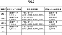
- FIG. 3 is a diagram showing an example of a vehicle type information table.
- the vehicle model information table stores a vehicle model ID for identifying the vehicle model and a vehicle sample image corresponding to the vehicle model indicated by the vehicle model ID in association with the vehicle model ID.
- the vehicle type information table stores each of the part area information indicating each area of the vehicle parts of the vehicle corresponding to the vehicle type indicated by the vehicle type ID in association with the vehicle type ID.
- the vehicle type information table stores a plurality of damage level reference images of the vehicle corresponding to the vehicle type indicated by the vehicle type ID in association with the vehicle type ID.
- the vehicle model ID is associated with information about the vehicle model in the vehicle table stored in the storage device 14.
- Information about the vehicle type includes elements such as manufacturer, vehicle name, model, model year, body shape, engine model, grade, and device variation.
- the vehicle model ID is an example of the vehicle model identification information, and may be any one that can uniquely identify the vehicle model, and a different vehicle model ID is assigned to a vehicle model having any one of the elements included in the vehicle model information.
- the table stores images, illustration data, and the like, but instead of storing various images and the like, a path for storing various images and the like may be stored.
- the vehicle type information table stores each of various images such as a vehicle sample image and a damage degree image, but instead of storing various images, each of the paths for storing various images may be stored.
- the control unit 23 is configured to be able to access various images via the path.
- the vehicle type information table stores each of the illustration data of the parts area information, but instead of storing each illustration data, each of the paths for storing each illustration data may be stored. In this case, the control unit 23 is configured to be able to access each illustration data via the path.
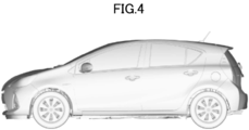
- FIG. 4 is a diagram showing an example of a vehicle sample image.
- the vehicle sample image is a sample image showing a vehicle corresponding to the vehicle type.
- the vehicle type information storage unit 21 stores a vehicle sample image corresponding to one vehicle type in association with the vehicle type ID.
- the vehicle sample image is an image showing a vehicle when viewed from a certain angle, and is an image showing a vehicle when viewed from the side, for example, as shown in FIG.
- the vehicle type information storage unit 21 stores one vehicle sample image for each vehicle type, but as described in the first modification, the vehicle type information storage unit 21 It is preferable to store a plurality of vehicle sample images for each vehicle type.
- the vehicle type information table may store the same vehicle sample image for vehicle types having similar vehicle appearances.
- the part area information is data representing the shape of a vehicle part using position information such as coordinates.
- the component area information is data represented in two dimensions indicating a vehicle component area in a vehicle sample image, and is a vector image.
- Each of the vehicle parts is associated with each of the parts area information.
- the position of the area of the vehicle part indicated by the part area information is associated with the position in the vehicle sample image.
- the area of the vehicle part indicated by the part area information is represented by using the position information such as the coordinates defined on the vehicle sample image.
- Vehicle parts are parts other than outer panel parts such as outer panel that require work on outer sheet metal, or outer panel parts such as headlamps and radiator supports. Therefore, the component area information stored in the vehicle type information table is the component area information indicating the area of the component other than the outer panel component or the component area information indicating the area of the outer panel component.
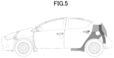
- FIG. 5 is component area information showing an area of a component other than the outer panel component.
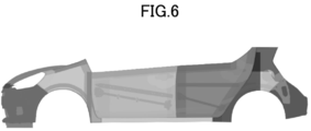
- FIG. 6 is component area information showing an area of the outer panel component. The position of the vehicle component region indicated by the component region information shown in FIGS. 5 and 6 is associated with the position in the vehicle sample image shown in FIG.
- FIG. 7 is a diagram showing an example of a damage level reference image.
- the damage level reference image is an image showing a damaged part of the vehicle according to the damage level.
- the damage level indicates the degree of damage to a part or the whole of the vehicle, and in the present embodiment, the estimation device 1 has a degree of damage in four stages from the level 1 with the smallest degree of damage to the level 4 with the largest degree of damage. To set.
- the part indicates a part of the vehicle identified from the appearance of the vehicle.
- the damage level reference image includes each image of each damage level of multiple sites.
- the stage of the damage level set by the estimation device 1 is not limited to this, and the estimation device 1 can set the degree of damage in a plurality of stages other than the four stages.
- the damage level reference image is also an image showing the damaged portion of the vehicle according to the set damage level.
- the damage level reference image includes an image showing each damage level of the front bumper damage levels 1 to 4 and an image showing each damage level of the front fender damage levels 1 to 4.
- the damage level reference image includes each image of each damage level of multiple sites so that the user can easily grasp the damage level, and the images are arranged for each site and for each damage level. It is the one that was arranged.
- the damage level reference image may include an image showing each degree of damage of damage levels 1 to 4 of other parts, or may include an image showing each degree of damage of damage levels 1 to 4 of the entire appearance of the vehicle. good.
- the damage level reference image is one image data including a plurality of images showing the degree of damage arranged for each site and for each damage level.
- the damage level reference image may include a plurality of image data associated with one vehicle model ID, and in this case, each image data is image data indicating the degree of damage of one level of one part. be.
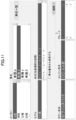
- FIG. 8 is a diagram showing an example of a repair information table.
- the repair information table stores the vehicle type ID, area code, damage level, vehicle parts, and repair details in association with each other.
- Each of the area codes is associated with each of the component area information.
- the area code is an example of the area identification information for specifying each of the component area information.
- the part area information is associated with the vehicle part, at least in the repair information table, as shown in FIG.
- the repair information table may store a code representing a vehicle part or a vehicle part name as an element of the vehicle part.
- the repair information table may store "replacement", “detachment”, “repair”, “sheet metal”, etc. as elements of the repair content, or a code representing the repair content (for example,). “00”, “01”, etc.) may be stored.
- the repair content is "sheet metal”
- the vehicle part associated with the repair information table is the outer panel.
- the area code "04-2300” shown in FIG. 8 represents the door panel of the left front door
- the vehicle part "2300” represents the door panel
- the area code "02-0010” shown in FIG. 8 represents a predetermined area of the front bumper
- the vehicle part "1434" represents the radiator support
- the vehicle part "0400” represents the headlamp.
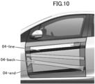
- 9 and 10 are examples of regions indicated by component region information corresponding to region codes.
- FIG. 9 shows the area of the door panel of the left front door corresponding to the area codes “04-2300” and “04-repair” shown in FIG. FIG.
- the repair content element "sheet metal" associated with the area code corresponding to the part area information indicating the area of the outer panel component is associated with the exponent in the repair information table or other table.
- the repair information table may include exponential information in the repair content element.
- the control unit 23 specifies the vehicle type based on the input regarding the estimated target vehicle to be the target of the repair estimate.
- FIG. 11 is an example of a screen for the control unit 23 to input the vehicle type to be displayed on the display device 13.
- the control unit 23 allows the user to select the vehicle type stored in the vehicle table, thereby selecting information on the vehicle type including the manufacturer, vehicle name, model, year, body shape, engine model, and grade. , Let me decide.
- the control unit 23 identifies the vehicle type (vehicle type ID) based on the information on the vehicle type determined according to the user operation.
- the control unit 23 causes the user to specify the vehicle type by having the user select information about the vehicle type and then selecting a confirmation button (not shown) or the like. As a result, the control unit 23 can specify the vehicle model ID.
- the control unit 23 acquires the vehicle sample image, the parts area information, and the damage level reference image corresponding to the specified vehicle type from the vehicle type information storage unit 21.
- the control unit 23 uses the specified vehicle model ID as a query to acquire a vehicle sample image, a part area information, and a damage level reference image associated with the vehicle model ID from the vehicle model information storage unit 21.
- the control unit 23 accepts the input of the damage level of the damaged part in which the user tries to input the damage range 31 in the vehicle to be estimated.
- the control unit 23 receives an input of the damage level of the most damaged part of the vehicle to be estimated.
- FIG. 12 is an example of a screen for the control unit 23 to let the user display on the display device 13 input the damage level.
- the damage level is associated with the damage range 31 of the damaged estimated vehicle.
- the control unit 23 displays the damage level reference image acquired from the vehicle model information storage unit 21 on the display device 13.
- the damage level reference image corresponds to the vehicle type specified by the control unit 23 and includes each image of each damage level of the plurality of parts.
- the control unit 23 provides a scroll bar and displays the damage level reference image so that the user can confirm all the images according to the user operation.
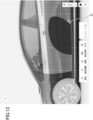
- the control unit 23 receives the input regarding the region corresponding to the position in the vehicle sample image as the input of the damage range 31. Therefore, the area of the damage range 31 is represented by using the position information such as the coordinates determined on the vehicle sample image.
- the control unit 23 displays a vehicle sample image in order for the user to input the damage range 31.
- the control unit 23 can also display a simple illustration showing the vehicle instead of the vehicle sample image in order to allow the user to input the damage range 31 more easily.
- FIG. 13 is an example of a screen for the control unit 23 to cause the user to display on the display device 13 to input the damage range 31.
- the control unit 23 stores a plurality of positions in the vehicle sample image in response to the user's mouse operation, and uses the area inside the boundary line composed of the stored positions as the input of the damage range 31. accept.
- the control unit 23 stores the position of the mouse pointer when clicked by the user as the boundary position.
- the control unit 23 stores the boundary position with the position of the mouse pointer moved while being clicked by the user as the boundary position.
- the control unit 23 determines whether or not the area indicated by each of the component area information acquired from the vehicle type information storage unit 21 and the damage range 31 that has received the input overlap. Both the part area information and the damage range 31 that has received the input have the area information corresponding to the position in the vehicle sample image.
- the control unit 23 can perform the above duplication determination by using a known method. In the present embodiment, the control unit 23 determines whether or not at least a part of the area indicated by the component area information is included in the damage range 31 that receives the input for each of the component area information acquired from the vehicle type information storage unit 21. By making a determination, the above duplication determination is performed. In one example, the control unit 23 performs the above duplication determination by determining whether or not any one of the plurality of boundary positions constituting the component area information is included in the damage range 31 that receives the input. ..
- control unit 23 determines whether or not at least a part of the damage range 31 for which the input is received is included in the area indicated by the part area information for each of the part area information acquired from the vehicle type information storage unit 21. Thereby, the above duplication determination can also be performed. Further, the control unit 23 determines whether or not at least a part of the area indicated by the component area information is included in the damage range 31 that has received the input, and has acquired at least a part of the damage range 31 that has received the input. It is also possible to determine whether or not the information is included in the region indicated by the component area information, and perform the above duplication determination assuming that those satisfying the two determination results are duplicated.
- the above-mentioned processing for determining duplication of the control unit 23 is an example, and can be freely changed as long as it does not deviate from the gist of the invention.
- the component area information may be a raster image or the like instead of a vector image, and the control unit 23 can perform arbitrary duplication determination according to the image format.
- the control unit 23 determines the area code corresponding to the component area information indicating the area determined to be duplicated.
- FIG. 14 is a diagram for explaining the overlap determination between the damage range 31 and the area indicated by each of the component area information.
- the control unit 23 determines that the area corresponding to the area codes “04-2300”, “04-repair”, “04-line”, and “04-back” overlaps with the damage range 31.
- the control unit 23 determines the vehicle parts and the repair contents of the vehicle parts based on the specified vehicle type ID associated with the repair information table, the determined area code, and the damage level for which the input is received. ..
- the control unit 23 acquires the vehicle parts and the repair contents of the vehicle parts associated with the specified vehicle type ID, the determined area code, and the damage level for which the input is received in the repair information table. In this case, for example, the control unit 23 uses the specified vehicle model ID, the specified area code, and the damage level for which the input is received as a query, and stores the vehicle parts and repair contents associated with these as a repair information storage unit. Obtained from 22. The control unit 23 determines the vehicle parts and the repair contents acquired from the repair information storage unit 22 as the vehicle parts to be repaired and the repair contents of the vehicle parts. In one example, when the repair content of the vehicle part is "sheet metal", the repair content of the vehicle part determined by the control unit 23 includes the index of the sheet metal.
- the control unit 23 when the received damage level is "1" to "3", the control unit 23 has "04-repair", "04-line” and “04-line” based on the repair information table shown in FIG. -The vehicle parts and repair contents associated with "back” are determined as the vehicle parts to be repaired and the repair contents of the vehicle parts. Further, for example, in FIG. 14, when the received damage level is "4", the control unit 23 repairs the vehicle parts and the repair contents associated with "04-2300" based on the repair information table shown in FIG. It is determined as the target vehicle parts and the repair contents of the vehicle parts.
- the storage device 14 stores the amount of each article (part cost) of the vehicle parts that can be replaced in association with the vehicle parts.
- the storage device 14 stores an index of replacement work of vehicle parts in association with vehicle parts that can be replaced.
- the control unit 23 is configured to be able to determine the parts cost and the index of the vehicle parts when the repair content of the determined vehicle parts to be repaired is "replacement”.
- the storage device 14 stores the index of the attachment / detachment work of the vehicle parts in association with the vehicle parts that can be the attachment / detachment target.
- the control unit 23 is configured to be able to determine the index of the vehicle parts when the repair content of the determined vehicle parts to be repaired is "detachment".
- the storage device 14 stores an index of repair work of the vehicle parts in association with the vehicle parts that can be repaired.
- the control unit 23 is configured to be able to determine the index of the vehicle parts when the repair content of the determined vehicle parts to be repaired is "repair”. Further, the control unit 23 is configured so that when the repair content of the determined vehicle part to be repaired is "sheet metal", the index of the sheet metal can be determined by the index associated with the element "sheet metal" of the repair content of the repair information table. Will be done.
- the above index shows the repair work time associated with the replacement or repair of goods.
- the storage device 14 also stores the index-corresponding unit price.
- the control unit 23 calculates the estimated amount of money based on the determined vehicle parts, the parts cost and index of the vehicle parts determined based on the repair contents of the vehicle parts, and the unit price corresponding to the index.
- a known calculation method can be used for calculating the estimated amount of money of the control unit 23 after determining the vehicle parts and the repair contents.
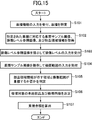
- FIG. 15 is a flowchart illustrating information processing executed in the estimation device 1 according to the embodiment of the present invention.
- the estimation device 1 displays an input reception screen as shown in FIG.
- the control unit 23 receives input of information on the vehicle type from the user via the input reception screen, and identifies the vehicle type ID based on the information on the vehicle type that has received the input (step 101).
- control unit 23 acquires the vehicle sample image, the parts area information, and the damage level reference image associated with the specified vehicle model ID from the vehicle model information storage unit 21 (step 102).
- control unit 23 displays a screen including the damage level reference image acquired from the vehicle type information storage unit 21 on the display device 13, and inputs the damage level associated with the damage range 31 from the user via the screen. Accept (step 103).
- control unit 23 displays a screen including the vehicle sample image on the display device 13, and receives input from the user regarding the region corresponding to the position in the vehicle sample image as the input of the damage range 31 via the screen ( Step 104).
- control unit 23 determines whether or not the area indicated by each of the component area information acquired from the vehicle type information storage unit 21 and the damage range 31 that has received the input overlap (step 105). Specifically, in step 105, the control unit 23 determines whether or not at least a part of the area indicated by the acquired component area information is included in the damage range 31 that has received the input, and at least the damage range 31 that has received the input. The above duplication determination is performed by determining at least one of whether or not the part is included in the area indicated by the acquired component area information.
- control unit 23 determines the vehicle parts and the repair contents of the vehicle parts based on the areas determined to overlap (step 106). Specifically, in step 106, the control unit 23 determines the area code corresponding to the component area information, and sets the determined area code, the specified vehicle model ID, and the damage level for which the input is received in the repair information table. Acquire the associated vehicle parts and repair details. The control unit 23 determines the acquired vehicle parts and repair contents as the vehicle parts to be repaired and the repair contents of the vehicle parts.
- the control unit 23 calculates the estimated amount of money based on the determined vehicle parts and the repair contents of the vehicle parts (step 107). Specifically, in step 107, the control unit 23 determines the estimated amount of money based on the determined vehicle parts, the parts cost and index of the vehicle parts determined based on the repair contents of the vehicle parts, and the unit price corresponding to the index. Is calculated. In step 107, the control unit 23 can calculate the estimated amount of money obtained by totaling all the estimated amounts calculated with respect to the parts cost and the index of the vehicle parts.
- the estimation device 1 includes a vehicle type information storage unit 21, a repair information storage unit 22, and a control unit 23.
- the vehicle type information storage unit 21 stores each of the part area information indicating each area of the vehicle parts of the vehicle corresponding to the vehicle type indicated by the vehicle type ID in association with the vehicle type ID.
- the repair information storage unit 22 stores the vehicle parts and the repair contents of the vehicle parts in association with the vehicle model ID, the area code, and the damage level.
- the control unit 23 acquires the vehicle sample image, the parts area information, and the damage level reference image associated with the specified vehicle type ID from the vehicle type information storage unit 21.
- the control unit 23 displays a screen including the damage level reference image on the display device 13, and receives an input of the damage level from the user.
- the user can input the damage level of the vehicle to be estimated while checking the damage degree of the vehicle corresponding to each damage level, and the user can input it more easily. It will be possible.
- the control unit 23 displays a screen including the vehicle sample image on the display device 13, and receives an input from the user regarding the area corresponding to the position in the vehicle sample image as an input of the damage range 31.
- the user can input the damage range 31 by drawing a region corresponding to the damaged portion of the vehicle to be estimated on the vehicle sample image displayed on the screen.
- the user can draw the boundary line of the damage range 31 by, for example, operating the mouse.
- the user can input the damage range 31 of the vehicle to be estimated while designating the position on the sample image showing the vehicle while checking the degree of damage to the vehicle. Can be entered more easily.
- the control unit 23 determines whether or not the area indicated by each of the component area information acquired from the vehicle type information storage unit 21 and the damage range 31 that has received the input overlap.
- the control unit 23 receives input of the vehicle identification information corresponding to the specified vehicle type and the area code corresponding to the part area information indicating the area determined to be duplicated, which are stored in association with the repair information storage unit 22. Based on the damage level and the damage level, the vehicle parts to be repaired and the repair contents of the vehicle parts are determined.
- the control unit 23 uses the repair information storage unit 22 to determine the vehicle parts to be repaired and the repair contents of the vehicle parts. Therefore, the user does not need to specify the vehicle parts or the vehicle parts.
- the user can more easily determine the vehicle part to be repaired and the repair content of the vehicle part by using the estimation device 1. Since the control unit 23 is configured to calculate the estimated amount of money based on the determined vehicle parts, the parts cost and index of the vehicle parts determined based on the repair contents of the vehicle parts, and the unit price corresponding to the index. In the present embodiment, the user can more easily calculate the estimated amount by using the estimation device 1.
- the above-mentioned effects are the same in other embodiments and examples.
- the modified embodiment shown below is also an embodiment of the present invention, and also in the modified embodiment shown below, the estimation device 1 is configured so that the user can input the input more easily.
- the vehicle type information storage unit 21 stores a plurality of vehicle sample images corresponding to one vehicle type, that is, a plurality of vehicle sample images associated with one vehicle type ID.
- the plurality of vehicle sample images associated with one vehicle type ID include one reference image and a selection image showing the vehicle when viewed from an angle different from the reference image.
- the reference image is an image showing the vehicle when viewed from the side
- the selected image is an image showing the vehicle when viewed from the front, an image showing the vehicle when viewed from the rear, and when viewed from above.
- the reference image is an image showing the vehicle when viewed from the side, but it can also be an image showing the vehicle when viewed from any direction.
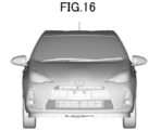
- FIG. 16 is a diagram showing an example of a vehicle sample image in the first modification embodiment.
- FIG. 16 is an image showing a vehicle when viewed from the front, and is an example of a selected image.
- FIG. 4 is an image showing a vehicle when viewed from the side, and is an example of a reference image.
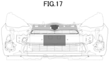
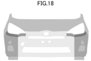
- 17 and 18 are diagrams showing an example of component area information in the first modification embodiment.
- the position of the vehicle component region indicated by the component region information shown in FIGS. 17 and 18 is associated with the position in the vehicle sample image shown in FIG.
- the position of the region indicated by the component area information is associated with the position in at least one of the reference image and the selected image according to the position of the region of the vehicle component indicated by the component area information.
- the position of the region indicated by the component region information may be associated with the position in any of the reference image and the selected image.
- the control unit 23 when the control unit 23 acquires the vehicle sample image corresponding to the specified vehicle type from the vehicle type information storage unit 21, the control unit 23 acquires the reference image and the selected image from the vehicle type information storage unit 21.
- the control unit 23 displays the reference image or the selected image acquired from the vehicle type information storage unit 21 on the display device 13, and inputs from the user regarding the area corresponding to the position in the displayed reference image or the selected image to the damage range. Accept as input of 31.
- the image first displayed on the display device 13 by the control unit 23 is a reference image.
- the control unit 23 displays the reference image acquired from the vehicle type information storage unit 21 on the display device 13 and accepts the input of the damage range 31, and when the damage range 31 that has received the input is within the predetermined range, another A message window 32 prompting the user to switch to an image showing the vehicle when viewed from an angle is displayed on the display device 13. In this case, the image showing the vehicle when viewed from another angle is the selected image.
- the predetermined range includes the area of the front part of the vehicle in the reference image.
- FIG. 19 is an example of a screen for the control unit 23 to cause the user to input the damage range 31 displayed on the display device 13, and is a diagram showing a screen including a display prompting the user to switch to the selected image.
- the screen for prompting the user to input the damage range 31 is a switching window for selecting whether to display a vehicle sample image showing the vehicle when viewed from the side, the front, or the upper direction. Includes 33.
- the switching window 33 displays an icon, an image, an icon such as text, or the like for switching the vehicle sample image.
- the control unit 23 displays the selected image on the display device 13 in response to the input from the user, for example, in response to the user's selection operation for an icon or the like in the switching window 33, and accepts the input of the damage range 31.
- the switching window 33 includes a reference image and a selected image acquired from the vehicle type information storage unit 21, and therefore includes a vehicle sample image showing the vehicle when viewed from a plurality of angles.
- the predetermined range may include at least one region of the front portion and the rear portion of the vehicle in the vehicle sample image.
- the user can input the damage range 31 to the vehicle when viewed from a plurality of angles, and the damage range 31 can be more accurately set. Input is possible.
- the position of the area of the vehicle part indicated by the part area information is associated with the position in the vehicle sample image of a part or all of the plurality of vehicle sample images. Therefore, for each of the plurality of vehicle sample images associated with the specified vehicle model ID, the control unit 23 includes the area indicated by each of the component area information acquired from the vehicle model information storage unit 21 and the damage range 31 that receives the input. Can be determined whether or not are duplicated. With the above configuration, the control unit 23 can more accurately determine the vehicle parts and the repair contents of the vehicle parts.
- the repair information storage unit 22 describes the vehicle parts and the repair contents of the incidental vehicle parts that need to be repaired in addition to the repair contents of the vehicle parts and the vehicle parts. And memorize in relation to the repair contents of vehicle parts.
- the repair information storage unit 22 may be stored in a table other than the repair information table, or may be stored in the repair information table.
- the repair information storage unit 22 may store the incidental vehicle parts and the repair contents of the incidental vehicle parts in association with the vehicle model ID, the area code, and the damage level.
- the control unit 23 determines the repair contents of the incidental vehicle parts and the incidental vehicle parts associated with the repair information storage unit 22 based on the determined vehicle parts and the repair contents of the vehicle parts.
- the control unit 23 calculates the estimated amount of the ancillary vehicle parts based on the determined ancillary vehicle parts and the parts cost and the index of the ancillary vehicle parts determined based on the repair contents of the ancillary vehicle parts, and the index corresponding unit price. do.
- the control unit 23 calculates the estimated amount by adding the estimated amount of the vehicle parts and the estimated amount of the incidental vehicle parts. With the above configuration, the control unit 23 can more accurately determine the vehicle parts and the repair contents of the vehicle parts.
- the control unit 23 uses the learning model to determine the likelihood of the damage level of the captured image that has received the input.
- the control unit 23 is configured to learn the learning model stored in the server device and to use the learning model by communicating with the server device via the communication device 15.
- the server device may be a cloud server.
- the server device stores a learning model in which captured images of vehicles classified by damage level are learned.
- the learned image of the vehicle is an image of the vehicle taken from various angles, and in the learning model, when the photographed image of an unknown vehicle is input, the damage level of the captured image, that is, the captured image is Infer the damage level of the indicated vehicle.
- the control unit 23 uses the learning model to determine the likelihood (probability) of the damage level corresponding to the damage level of the vehicle indicated by the captured image that has received the input.
- the control unit 23 displays the likelihood of the damage level determined on the display device 13 as the proposal information to the user.
- FIG. 20 is an example of a screen for the control unit 23 in the third modification embodiment to cause the user to input the damage level displayed on the display device 13.
- FIG. 20 shows that the probability that the damage level of the vehicle indicated by the captured image that received the input is the damage level 3 is the highest at 50%, and the control unit 23 displays the damage level 3 as the proposal information. .. With such a configuration, the user can input the damage level while referring to the proposal information.
- the control unit 23 can specify the vehicle portion of the captured image that has received the input by using the learning model.
- the server device stores a learning model in which captured images of the vehicle classified for each vehicle part are learned.
- the vehicle part is, for example, a front part, a rear part, a side part, and the like.
- the learned image of the vehicle is an image of the vehicle taken from various angles, and the learning model infers the vehicle part of the photographed image when the photographed image of the unknown vehicle is input.
- the control unit 23 uses the learning model to determine the likelihood (probability) of the vehicle part indicated by the captured image that has received the input, and classifies the vehicle part into predetermined types according to the high likelihood. do.
- control unit 23 does not accept the input regarding the estimated target vehicle to be the target of the repair estimate by the user operation.
- the control unit 23 identifies the vehicle model ID of the vehicle to be estimated based on the vehicle model information received from another system or device via the communication device 15.
- the vehicle type information storage unit 21 does not store the vehicle sample image corresponding to the vehicle type. Therefore, the control unit 23 does not acquire the vehicle sample image from the vehicle type information storage unit 21.
- the storage device 14 stores a general vehicle sample image that does not correspond to the vehicle type, and the control unit 23 displays the general vehicle sample image on the display device 13 when the user is made to input the damage range 31.
- the user can input the damage range 31 of the vehicle to be estimated while designating the position on the sample image showing the vehicle while checking the degree of damage to the vehicle. Can be entered more easily.
- the control unit 23 receives the input of the damage level, receives the input of the damage range 31 associated with the damage level, and then further receives the input of the damage level to obtain the damage.
- the input of the damage range 31 associated with the level can be accepted.
- the control unit 23 can repeat and execute the processes of steps 103 and 104 of the flowchart shown in FIG. 15 many times.
- the control unit 23 can more accurately determine the vehicle parts and the repair contents of the vehicle parts.
- the control unit 23 changes the order of the steps in the flowchart shown in FIG. 15, and after receiving the input of the damage range 31, the damage associated with the damage range 31. Accepts level input.
- the control unit 23 can repeat and execute the processes of steps 104 and 103 of the flowchart shown in FIG. 15 many times.
- the control unit 23 when receiving the input of the damage range 31, the control unit 23 receives the input of the damage range 31 at each of a plurality of stages indicating the relative level of the damage. With such a configuration, the user can input the damage range 31 corresponding to a plurality of stages on the vehicle sample image, so that the user can input more easily.
- FIG. 21 is an example of a screen for the control unit 23 in the seventh modification embodiment to cause the user to input the damage range displayed on the display device 13. After receiving the input of the first damage range 31a, the control unit 23 can receive the input of the second damage range 31b within the first damage range 31a.
- the control unit 23 associates the first damage range 31a with the damage level 2 and the second damage range 31b with the damage level 3. be able to.
- the control unit 23 can accept the input of the first damage range 31a and then the input of the second damage range 31b surrounding the first damage range 31a.
- the control unit 23 associates the first damage range 31a with the damage level 2 and associates the second damage range 31b with the damage level 1. be able to.
- the vehicle type information storage unit 21 does not store the damage level reference image
- the repair information storage unit 22 does not store the damage level.
- the control unit 23 does not accept the input of the damage level, but accepts the input of the damage range 31. In this case, the damage range 31 is not associated with the damage level.
- the control unit 23 is based on the vehicle identification information corresponding to the specified vehicle type and the area code corresponding to the part area information indicating the area determined to be duplicated, which is stored in association with the repair information storage unit 22. Determine the vehicle parts to be repaired and the repair contents of the vehicle parts. In this case, the control unit 23 executes step 104 without executing step 103 shown in FIG.
- the user can input the damage range 31 of the vehicle to be estimated while designating the position on the sample image showing the vehicle while checking the degree of damage to the vehicle. Can be entered more easily.
- the estimated amount corresponding to the damage level cannot be calculated, but when performing a simple calculation, the user can more easily use the estimation device 1 to calculate the vehicle parts to be repaired and the vehicle parts. It is possible to determine the repair contents of vehicle parts and calculate the estimated amount.
- the estimation device 1 does not include the repair information storage unit 22.
- the part area information includes information about the vehicle parts in addition to the data representing the shape of the vehicle parts.
- the control unit 23 determines the vehicle parts and the repair contents of the vehicle parts based on the areas determined to overlap. In one example, the control unit 23 determines the vehicle parts using information about the vehicle parts, including the parts area information indicating the areas determined to overlap. In this case, the control unit 23 determines the damage level based on at least one of the shape and size of the entire region determined to overlap, and determines the repair content of the vehicle parts. Also in the ninth modification embodiment, the user can input the damage range 31 of the vehicle to be estimated while designating the position on the sample image showing the vehicle while checking the degree of damage to the vehicle.
- the estimated amount corresponding to the damage level cannot be calculated, but when performing a simple calculation, the user can more easily use the estimation device 1 to calculate the vehicle parts to be repaired and the vehicle parts. It is possible to determine the repair contents of vehicle parts and calculate the estimated amount.
- the vehicle model information storage unit 21 stores one component area information in association with one vehicle model ID.
- One part area information has data representing the shape of each vehicle part, the data about each vehicle part is identifiable, and each data is associated with an area code.
- the repair information table does not store the vehicle model ID.
- the storage device 14 stores a repair information table for each vehicle type ID, and the control unit 23 determines the vehicle parts and the repair contents of the vehicle parts by using the repair information table corresponding to the specified vehicle type ID.
- the input device 12 and the display device 13 are realized by the touch panel, and the control unit 23 causes the user to input the damage range 31 in response to the user's touch operation on the touch panel.
- the control unit 23 draws the boundary line of the damage range 31 in response to the touch operation of the user, and accepts the area inside the boundary line as the input of the damage range 31.
- the estimation device 1 is realized by the server-client system.
- the estimation system 2 includes a server 4 and one or more clients 6. These are connected to each other by network 8.
- FIG. 22 is a diagram showing an example of the overall configuration of the estimation system 2 of the thirteenth modified embodiment.
- the server 4 includes a vehicle type information storage unit 21, a repair information storage unit 22, and a control unit 23, and the client 6 has a function of communicating with the server 4 and functions as a thin client terminal.
- the client 6 may be configured to have some functions of the server 4.
- the estimation device 1 in all the embodiments can be realized by the estimation system 2 in the modified embodiment.
- the storage device 14 stores the index table, and the index when the repair content of the determined vehicle part to be repaired is "sheet metal" is an index table (not shown). Is determined by. As a general rule, when the repair content is "sheet metal", the vehicle part to be repaired is the outer panel, so the index table determines the index of the outer panel.
- the elements of the repair content of the vehicle parts in the repair information table do not include the sheet metal index and are not associated with the sheet metal index.
- the exponent table is a table in which an exponent is associated with a range of difficulty rank and area of damage range.
- the difficulty level is an index indicating the difficulty level of repair when the repair content is "sheet metal", and is associated with each of a plurality of area code combinations for each vehicle part.
- the difficulty rank may also be associated with one area code.
- the difficulty rank may be determined for each vehicle part by a difficulty rank table in which each of one area code and a combination of a plurality of area codes is associated with the difficulty rank, or whether each of the area codes is included. It may be determined by the judgment of whether or not.
- the control unit 23 has a difficulty level when the area code corresponding to the component area information indicating the area determined to overlap with the damage range 31 that has received the input includes "04-line” or "04-end".
- the difficulty rank is determined as in the difficulty "C”.
- the control unit 23 calculates the area of the area of the damage range 31 that receives the input. At this time, the control unit 23 can calculate the area by using the vehicle sample image and the information associated with the vehicle model ID. Preferably, the control unit 23 further uses the component area information to calculate the area for each vehicle component (outer panel).
- the control unit 23 when the repair content of the determined vehicle part to be repaired is "sheet metal", the control unit 23 indicates an area determined to overlap with the damage range 31 with respect to the vehicle part and the repair content.
- the difficulty rank is determined from one or more area codes corresponding to the component area information. Then, with respect to the vehicle parts and repair contents, the control unit 23 acquires an index associated with the determined difficulty rank and the range of the area to which the calculated area corresponds in the index table, and uses the index as the index of the vehicle parts. Determined as an index for sheet metal. With respect to the vehicle parts and repair contents, the control unit 23 calculates an estimated amount using the determined index and the index-corresponding unit price.
- the estimation device 1 communicates with a database server or the like that stores the index table, transmits information regarding one or more area codes determined by the control unit 23, and receives the index corresponding to the area code.
- the server may be a server capable of supplying the computer with a program that realizes the functions of the embodiment of the present invention described above and the information processing shown in the flowchart.
- it can be a virtual machine that realizes the functions of the embodiment of the present invention described above and the information processing shown in the flowchart.
- the processing or operation can be freely performed in a certain step as long as there is no contradiction in the processing or operation such as using data that should not be available in that step. Can be changed.
- each of the examples described above is an example for explaining the present invention, and the present invention is not limited to these examples.
- the way of holding data in each storage unit or database is an example and can be freely changed as long as it does not deviate from the gist of the invention.
- the present invention can be carried out in various forms as long as it does not deviate from the gist thereof.
- Estimating device 2 Estimating system 4 Server 6 Client 8 Network 11 Processor 12 Input device 13 Output device 14 Storage device 15 Communication device 16 Bus 21 Vehicle type information storage unit 22 Repair information storage unit 23 Control unit 31 Damage range 32 Message window 33 For switching window
Landscapes
- Engineering & Computer Science (AREA)
- Business, Economics & Management (AREA)
- Strategic Management (AREA)
- Development Economics (AREA)
- Theoretical Computer Science (AREA)
- General Physics & Mathematics (AREA)
- Physics & Mathematics (AREA)
- Finance (AREA)
- Human Resources & Organizations (AREA)
- Marketing (AREA)
- Quality & Reliability (AREA)
- General Business, Economics & Management (AREA)
- Entrepreneurship & Innovation (AREA)
- Accounting & Taxation (AREA)
- Economics (AREA)
- Operations Research (AREA)
- Game Theory and Decision Science (AREA)
- Tourism & Hospitality (AREA)
- Computer Vision & Pattern Recognition (AREA)
- Management, Administration, Business Operations System, And Electronic Commerce (AREA)
- Electrical Discharge Machining, Electrochemical Machining, And Combined Machining (AREA)
- Communication Control (AREA)
Abstract
L'invention concerne un dispositif qui peut être actionné plus facilement par un utilisateur. La présente invention concerne un dispositif d'estimation qui calcule une quantité d'argent estimée requise pour la réparation de véhicule, et est pourvu d'une unité de stockage d'informations sur le type de véhicule qui stocke des informations d'identification de type de véhicule pour identifier un type de véhicule et des informations de zone de partie indiquant chaque zone de parties de véhicule en association les unes avec les autres. La position de la zone indiquée par les informations de zone de partie correspond à la position dans une image d'échantillon de véhicule représentant le véhicule correspondant au type de véhicule. Le dispositif d'estimation : identifie le type de véhicule sur la base de l'entrée concernant un véhicule à estimer ; acquiert, à partir de l'unité de stockage d'informations de type de véhicule, les informations de zone de partie correspondant au type de véhicule identifié ; reçoit, en tant qu'entrée d'une plage de dommages, l'entrée relative à la zone correspondant à la position dans l'image d'échantillon de véhicule ; détermine si la zone indiquée par les informations de zone de partie acquises et l'entrée reçue de la plage de dommages se chevauchent ou pas ; détermine des parties de véhicule et des détails de réparation sur la base des zones déterminées comme se chevauchant ; et calcule la quantité d'argent estimée sur la base des parties de véhicule déterminées et des détails de réparation.
Priority Applications (2)
| Application Number | Priority Date | Filing Date | Title |
|---|---|---|---|
| EP21747849.4A EP4099254A4 (fr) | 2020-01-31 | 2021-02-01 | Dispositif d'estimation, système d'estimation, procédé d'estimation et programme |
| US17/796,391 US20240013266A1 (en) | 2020-01-31 | 2021-02-01 | Estimation apparatus, estimation system, and estimation method |
Applications Claiming Priority (2)
| Application Number | Priority Date | Filing Date | Title |
|---|---|---|---|
| JP2020-015476 | 2020-01-31 | ||
| JP2020015476A JP7030292B2 (ja) | 2020-01-31 | 2020-01-31 | 見積装置、見積システム、見積方法及びプログラム |
Publications (1)
| Publication Number | Publication Date |
|---|---|
| WO2021153796A1 true WO2021153796A1 (fr) | 2021-08-05 |
Family
ID=77078154
Family Applications (1)
| Application Number | Title | Priority Date | Filing Date |
|---|---|---|---|
| PCT/JP2021/003453 WO2021153796A1 (fr) | 2020-01-31 | 2021-02-01 | Dispositif d'estimation, système d'estimation, procédé d'estimation et programme |
Country Status (5)
| Country | Link |
|---|---|
| US (1) | US20240013266A1 (fr) |
| EP (1) | EP4099254A4 (fr) |
| JP (2) | JP7030292B2 (fr) |
| TW (1) | TWI813939B (fr) |
| WO (1) | WO2021153796A1 (fr) |
Cited By (1)
| Publication number | Priority date | Publication date | Assignee | Title |
|---|---|---|---|---|
| WO2023017617A1 (fr) * | 2021-08-13 | 2023-02-16 | コグニビジョン株式会社 | Dispositif, procédé et programme de traitement d'informations pour estimer des informations d'endommagement de véhicule à partir d'une image de véhicule, et procédé et système pour générer un modèle entraîné |
Citations (5)
| Publication number | Priority date | Publication date | Assignee | Title |
|---|---|---|---|---|
| JP2005008060A (ja) * | 2003-06-19 | 2005-01-13 | Tsubasa System Co Ltd | 損傷解析支援システム |
| JP2008310535A (ja) | 2007-06-13 | 2008-12-25 | Broadleaf:Kk | 車両/部品情報提供装置および方法 |
| JP2016151890A (ja) | 2015-02-17 | 2016-08-22 | 株式会社ブロードリーフ | プログラム、見積方法および見積装置 |
| JP2019046234A (ja) * | 2017-09-04 | 2019-03-22 | 株式会社タウ | 中古車査定システム |
| JP2019114059A (ja) * | 2017-12-22 | 2019-07-11 | 三井住友海上火災保険株式会社 | 判定装置、修理費用判定システム、判定方法、および判定プログラム |
Family Cites Families (20)
| Publication number | Priority date | Publication date | Assignee | Title |
|---|---|---|---|---|
| JPH07101423B2 (ja) * | 1992-12-28 | 1995-11-01 | 株式会社イー・エー・シー | 自動車修理の見積りシステム |
| JPH10162053A (ja) * | 1996-12-04 | 1998-06-19 | Tsubasa Syst Kk | 車両修理費見積もりシステム |
| JP3193005B2 (ja) | 1998-08-21 | 2001-07-30 | 翼システム株式会社 | 車両修理費見積システム及びプログラムを記録したコンピュータ可読媒体 |
| TW542986B (en) * | 2001-11-05 | 2003-07-21 | Tsubasa System Co Ltd | Assessment method for charges of car repairs and the assessment system |
| JP4296022B2 (ja) | 2003-04-18 | 2009-07-15 | 株式会社ブロードリーフ | 損傷解析支援システム |
| JP4918644B2 (ja) | 2005-06-16 | 2012-04-18 | 株式会社ブロードリーフ | 損傷車両画像作成システム及びこれを用いて構築された車両修理費見積システム。 |
| US9721301B2 (en) * | 2010-06-19 | 2017-08-01 | SHzoom LLC | Vehicle repair cost estimate acquisition system and method |
| US10360601B1 (en) * | 2014-12-11 | 2019-07-23 | Alexander Omeed Adegan | Method for generating a repair estimate through predictive analytics |
| US11144889B2 (en) * | 2016-04-06 | 2021-10-12 | American International Group, Inc. | Automatic assessment of damage and repair costs in vehicles |
| US10692050B2 (en) * | 2016-04-06 | 2020-06-23 | American International Group, Inc. | Automatic assessment of damage and repair costs in vehicles |
| US20170293898A1 (en) * | 2016-04-11 | 2017-10-12 | John Rampton | Static ctyptographic currency value |
| US10706321B1 (en) * | 2016-05-20 | 2020-07-07 | Ccc Information Services Inc. | Image processing system to align a target object in a target object image with an object model |
| CN106600420A (zh) * | 2016-11-16 | 2017-04-26 | 中国平安财产保险股份有限公司 | 一种车险智能定损网询询价方法及系统 |
| US11710185B1 (en) * | 2018-05-14 | 2023-07-25 | State Farm Mutual Automobile Insurance Company | Smart estimatics methods and systems |
| US11238506B1 (en) * | 2018-06-15 | 2022-02-01 | State Farm Mutual Automobile Insurance Company | Methods and systems for automatic processing of images of a damaged vehicle and estimating a repair cost |
| US10832065B1 (en) * | 2018-06-15 | 2020-11-10 | State Farm Mutual Automobile Insurance Company | Methods and systems for automatically predicting the repair costs of a damaged vehicle from images |
| CN109086967A (zh) * | 2018-07-05 | 2018-12-25 | 北京精友时代信息技术发展有限公司 | 一种车险网上定损系统平台及方法 |
| EP3629257A1 (fr) * | 2018-09-28 | 2020-04-01 | Mitchell International, Inc. | Procédés d'estimation de données de réparation utilisant l'intelligence artificielle et dispositifs associés |
| US10949814B1 (en) * | 2019-05-09 | 2021-03-16 | Ccc Information Services Inc. | Intelligent vehicle repair estimation system |
| CN110705361A (zh) * | 2019-09-06 | 2020-01-17 | 中国平安财产保险股份有限公司 | 车辆智能定损方法、装置、计算机系统及可读存储介质 |
-
2020
- 2020-01-31 JP JP2020015476A patent/JP7030292B2/ja active Active
-
2021
- 2021-01-28 TW TW110103187A patent/TWI813939B/zh active
- 2021-02-01 EP EP21747849.4A patent/EP4099254A4/fr active Pending
- 2021-02-01 WO PCT/JP2021/003453 patent/WO2021153796A1/fr active Application Filing
- 2021-02-01 US US17/796,391 patent/US20240013266A1/en active Pending
- 2021-10-08 JP JP2021166330A patent/JP2022002138A/ja active Pending
Patent Citations (5)
| Publication number | Priority date | Publication date | Assignee | Title |
|---|---|---|---|---|
| JP2005008060A (ja) * | 2003-06-19 | 2005-01-13 | Tsubasa System Co Ltd | 損傷解析支援システム |
| JP2008310535A (ja) | 2007-06-13 | 2008-12-25 | Broadleaf:Kk | 車両/部品情報提供装置および方法 |
| JP2016151890A (ja) | 2015-02-17 | 2016-08-22 | 株式会社ブロードリーフ | プログラム、見積方法および見積装置 |
| JP2019046234A (ja) * | 2017-09-04 | 2019-03-22 | 株式会社タウ | 中古車査定システム |
| JP2019114059A (ja) * | 2017-12-22 | 2019-07-11 | 三井住友海上火災保険株式会社 | 判定装置、修理費用判定システム、判定方法、および判定プログラム |
Non-Patent Citations (1)
| Title |
|---|
| See also references of EP4099254A4 |
Cited By (1)
| Publication number | Priority date | Publication date | Assignee | Title |
|---|---|---|---|---|
| WO2023017617A1 (fr) * | 2021-08-13 | 2023-02-16 | コグニビジョン株式会社 | Dispositif, procédé et programme de traitement d'informations pour estimer des informations d'endommagement de véhicule à partir d'une image de véhicule, et procédé et système pour générer un modèle entraîné |
Also Published As
| Publication number | Publication date |
|---|---|
| JP7030292B2 (ja) | 2022-03-07 |
| EP4099254A4 (fr) | 2024-02-28 |
| TWI813939B (zh) | 2023-09-01 |
| JP2021124759A (ja) | 2021-08-30 |
| JP2022002138A (ja) | 2022-01-06 |
| EP4099254A1 (fr) | 2022-12-07 |
| US20240013266A1 (en) | 2024-01-11 |
| TW202134995A (zh) | 2021-09-16 |
Similar Documents
| Publication | Publication Date | Title |
|---|---|---|
| CN103493051B (zh) | 用于估计对汽车的碰撞损伤的系统、方法和设备 | |
| JP2018106662A (ja) | 情報処理装置、情報処理方法、プログラム | |
| US20140056478A1 (en) | Product identification using mobile device | |
| JP2019114059A (ja) | 判定装置、修理費用判定システム、判定方法、および判定プログラム | |
| CN109976314B (zh) | 一种故障码维修案例的查询方法及系统 | |
| JP6636097B2 (ja) | 空間のビジュアルモデルレイアウトを作成する方法、装置およびデバイス | |
| WO2021153796A1 (fr) | Dispositif d'estimation, système d'estimation, procédé d'estimation et programme | |
| CN110489188A (zh) | 由桌面应用生成移动应用程序的计算机实现的方法和系统 | |
| WO2021024459A1 (fr) | Dispositif de traitement, dispositif de comptabilité, procédé de traitement et programme | |
| JP5596827B1 (ja) | 車両査定支援装置、および車両査定支援システム | |
| KR20160134402A (ko) | 자동차의 튜닝견적 자동산출시스템 및 그 방법 | |
| JP6844902B2 (ja) | 査定支援システム、そのサーバ装置、端末、査定支援方法 | |
| JP4057571B2 (ja) | 画像分析システム及び画像分析方法 | |
| US11682059B2 (en) | Method, computer readable storage devices, and computer device for mapping visual diagram portions to parts listing information | |
| JP7340896B1 (ja) | 検索表示プログラム、検索表示装置、及び検索表示システム | |
| CN112036443A (zh) | 一种图像数据中物体轮廓的标注方法和装置 | |
| CN111143912A (zh) | 展示标注方法及相关产品 | |
| JP2020013348A (ja) | ジェスチャ検出装置、ジェスチャ検出方法、およびジェスチャ検出制御プログラム | |
| JP7079286B2 (ja) | 修理見積り支援システムおよび支援情報分析装置 | |
| CN116631065B (zh) | 手势识别方法及装置 | |
| CN111651473B (zh) | 保单生成方法、装置、设备及计算机可读存储介质 | |
| WO2023017617A1 (fr) | Dispositif, procédé et programme de traitement d'informations pour estimer des informations d'endommagement de véhicule à partir d'une image de véhicule, et procédé et système pour générer un modèle entraîné | |
| JP2001250009A (ja) | 車両修理見積システム,方法および見積プログラムを格納した媒体 | |
| JP2016151890A (ja) | プログラム、見積方法および見積装置 | |
| CN117851616A (zh) | 车辆功能查询的方法、装置、计算机设备及存储介质 |
Legal Events
| Date | Code | Title | Description |
|---|---|---|---|
| 121 | Ep: the epo has been informed by wipo that ep was designated in this application |
Ref document number: 21747849 Country of ref document: EP Kind code of ref document: A1 |
|
| WWE | Wipo information: entry into national phase |
Ref document number: 17796391 Country of ref document: US |
|
| NENP | Non-entry into the national phase |
Ref country code: DE |
|
| ENP | Entry into the national phase |
Ref document number: 2021747849 Country of ref document: EP Effective date: 20220831 |