WO2021153134A1 - 作業機 - Google Patents
作業機 Download PDFInfo
- Publication number
- WO2021153134A1 WO2021153134A1 PCT/JP2020/048842 JP2020048842W WO2021153134A1 WO 2021153134 A1 WO2021153134 A1 WO 2021153134A1 JP 2020048842 W JP2020048842 W JP 2020048842W WO 2021153134 A1 WO2021153134 A1 WO 2021153134A1
- Authority
- WO
- WIPO (PCT)
- Prior art keywords
- rotating shaft
- axial direction
- housing
- fan
- stator
- Prior art date
Links
Images


Classifications
-
- F—MECHANICAL ENGINEERING; LIGHTING; HEATING; WEAPONS; BLASTING
- F21—LIGHTING
- F21V—FUNCTIONAL FEATURES OR DETAILS OF LIGHTING DEVICES OR SYSTEMS THEREOF; STRUCTURAL COMBINATIONS OF LIGHTING DEVICES WITH OTHER ARTICLES, NOT OTHERWISE PROVIDED FOR
- F21V33/00—Structural combinations of lighting devices with other articles, not otherwise provided for
- F21V33/008—Leisure, hobby or sport articles, e.g. toys, games or first-aid kits; Hand tools; Toolboxes
- F21V33/0084—Hand tools; Toolboxes
-
- B—PERFORMING OPERATIONS; TRANSPORTING
- B27—WORKING OR PRESERVING WOOD OR SIMILAR MATERIAL; NAILING OR STAPLING MACHINES IN GENERAL
- B27C—PLANING, DRILLING, MILLING, TURNING OR UNIVERSAL MACHINES FOR WOOD OR SIMILAR MATERIAL
- B27C5/00—Machines designed for producing special profiles or shaped work, e.g. by rotary cutters; Equipment therefor
- B27C5/10—Portable hand-operated wood-milling machines; Routers
-
- B—PERFORMING OPERATIONS; TRANSPORTING
- B25—HAND TOOLS; PORTABLE POWER-DRIVEN TOOLS; MANIPULATORS
- B25F—COMBINATION OR MULTI-PURPOSE TOOLS NOT OTHERWISE PROVIDED FOR; DETAILS OR COMPONENTS OF PORTABLE POWER-DRIVEN TOOLS NOT PARTICULARLY RELATED TO THE OPERATIONS PERFORMED AND NOT OTHERWISE PROVIDED FOR
- B25F5/00—Details or components of portable power-driven tools not particularly related to the operations performed and not otherwise provided for
- B25F5/008—Cooling means
-
- B—PERFORMING OPERATIONS; TRANSPORTING
- B25—HAND TOOLS; PORTABLE POWER-DRIVEN TOOLS; MANIPULATORS
- B25F—COMBINATION OR MULTI-PURPOSE TOOLS NOT OTHERWISE PROVIDED FOR; DETAILS OR COMPONENTS OF PORTABLE POWER-DRIVEN TOOLS NOT PARTICULARLY RELATED TO THE OPERATIONS PERFORMED AND NOT OTHERWISE PROVIDED FOR
- B25F5/00—Details or components of portable power-driven tools not particularly related to the operations performed and not otherwise provided for
- B25F5/02—Construction of casings, bodies or handles
- B25F5/021—Construction of casings, bodies or handles with guiding devices
Definitions
- the present invention relates to a working machine.
- Patent Document 1 discloses a router (working machine) that performs cutting work on a material to be cut by rotating a tip tool by driving a motor. Specifically, when the operator grasps the handle of the router and pushes the router downward, the tip tool comes into contact with the material to be cut and the cutting work is performed on the material to be cut. ..
- some routers are provided with a lighting unit that illuminates the periphery of the tip tool in order to improve workability during cutting.
- the lighting unit when the lighting unit is mounted on the router described in Patent Document 1, it is necessary to separately provide a member or the like for holding the lighting unit. Therefore, there is a possibility that the number of parts may increase. Therefore, when mounting the lighting unit on the router, it is desirable to have a structure that can illuminate the surroundings of the tip tool while suppressing an increase in the number of parts. Further, when the lighting unit is mounted, it is desirable to suppress the deterioration of the assembling property.
- One or more embodiments of the present invention include a rotary shaft, a rotor configured to be integrally rotatable on the rotary shaft, and a stator arranged on the radial outer side of the rotor.
- a fan provided on the rotating shaft and arranged on one side of the rotating shaft in the axial direction with respect to the rotor and the stator, a housing for accommodating the motor, and one end portion of the rotating shaft in the axial direction.
- One or more embodiments of the present invention include a rotary shaft, a rotor configured to be integrally rotatable on the rotary shaft, and a stator arranged on the radial outer side of the rotor.
- the tip tool is provided, an illumination unit including a light source that irradiates the emitted light toward the periphery of the tip tool, and the stator provided on one side of the rotation axis in the axial direction. It is a working machine provided with a holding member that holds the illumination unit and restricts the movement of the rotating shaft in the stator to one side in the axial direction.
- the housing includes a first housing that houses the motor, and a second housing that is provided on one side of the rotating shaft in the axial direction with respect to the first housing.
- the holding member is a working machine sandwiched between the first housing and the second housing in the axial direction of the rotating shaft.
- the second housing is formed with an engaging portion engaged with the holding member, and the rotation of the holding member in the circumferential direction of the rotating shaft is the same. It is a working machine regulated by the engaging part.
- the holding member extends from a base portion arranged between the rotor, the stator, and the fan, and from the base portion to one side in the axial direction of the rotating shaft. It is a working machine including an extension portion and the lighting portion, which is held at the tip end portion of the extension portion.
- the holding member extends from a base located between the rotor, the stator, and the fan, and from the base to one side of the rotating shaft in the axial direction.
- the illuminating portion is held at the base end portion of the extending portion, and the extending portion transmits the light emitted by the light source to transmit the light. Is a working machine in which light is emitted from the tip of the extending portion toward the periphery of the tip tool.
- a groove portion is formed in the base portion so as to be open to the other side in the axial direction of the rotation shaft, and wiring connected to the illumination portion is provided in the groove portion. It is a work machine that has been arranged.
- the holding member holds a pair of the lighting units, and a wiring connecting the pair of the lighting units is arranged in the groove. Is.
- a split housing is provided on the other side of the rotating shaft in the axial direction with respect to the housing, and the split housing is provided with respect to the axial direction of the rotating shaft. It is a work machine that is configured so that it can be divided in orthogonal directions.
- One or more embodiments of the present invention is a working machine provided with a control unit for controlling lighting and extinguishing of the lighting unit in the divided housing.
- One or more embodiments of the present invention is a working machine in which a battery for supplying electric power to the lighting unit is detachably provided in the divided housing.
- One or more embodiments of the present invention include a rotating shaft, a rotor configured to be integrally rotatable on the rotating shaft, and a stator arranged radially outside the rotor.
- a fan provided on the rotating shaft and arranged on one side of the rotating shaft in the axial direction with respect to the rotor and the stator, a housing for accommodating the motor, and one end portion of the rotating shaft in the axial direction.
- the holding member comprises a tip tool, a lighting unit including a light source that irradiates the emitted light toward the periphery of the tip tool, and a holding member that holds the lighting unit.
- a base portion arranged between the rotor and the stator and the fan, and a base portion extending from the base portion to one side in the axial direction of the rotation shaft to hold the illumination portion and light emitted by the light source. It is configured to include an extending portion that is transmitted and irradiates the light from the tip portion toward the periphery of the tip tool, and the tip portion of the extending portion is a shaft of the rotating shaft rather than the fan. It is a work machine located on one side of the direction.
- FIG. 5 is an exploded perspective view of the router main body of the router shown in FIG. 1 as viewed diagonally from the front to the right. It is sectional drawing (4-4 line sectional drawing of FIG. 1) which looked at the router shown in FIG. 1 from the lower side of the router main body. It is sectional drawing (5-5 line sectional drawing of FIG. 4) seen from the front side which shows the inside of the router main body shown in FIG. It is sectional drawing (6-6 line sectional drawing of FIG. 4) which showed the inside of the router main body shown in FIG. 4 from the front side which shows the position of the illumination hole.
- FIG. 5 is a plan sectional view (cross-sectional view taken along line 7-7 of FIG. 5) of the motor housed in the motor housing portion shown in FIG. 5 as viewed from above at the position of the lower end portion of the motor.
- FIG. 5 is a plan sectional view (FIG. 8-8 sectional view of FIG. 5) of the holding ring shown in FIG. 5 in a state of being housed in the end bracket, as viewed from above at the position of the upper end portion of the holding ring.
- (A) is an enlarged perspective view showing the holding ring shown in FIG. 3, and
- (B) is a front view of the holding ring of (A) seen from the front side.
- FIG. 8 It is a top view which shows the state which the illuminating part was held by the holding ring shown in FIG. 8 in an enlarged manner.
- A is a cross-sectional view (cross-sectional view taken along the line 11A-11A of FIG. 10) showing the ring base of the holding ring shown in FIG. 10 at the position of the reinforcing rib
- B is the holding ring shown in FIG.
- It is a cross-sectional view (11B-11B line cross-sectional view of FIG. 10) which shows around the holding column.
- C) is a cross-sectional view (11C-11C line cross-sectional view of FIG. 11B) showing a vertical intermediate portion of the holding column shown in (B), and (D) is (B).
- FIG. 11B It is a cross-sectional view (11D-11D line cross-sectional view of FIG. 11B) seen from the upper side which shows the lower end part of the holding column shown by).
- (A) is a cross-sectional view seen from the front side showing a modified example of the holding ring when the fan shown in FIG. 6 is a centrifugal fan
- (B) is a right side showing the fan and the holding ring of (A).
- 11 is a cross-sectional view corresponding to FIG. 11B showing a modified example of the holding ring when the vertical position of the illumination unit shown in FIG. 11B is changed.
- the router 10 as a "working machine" according to the present embodiment will be described with reference to the drawings.
- the arrows UP, FR, and RH appropriately shown in the drawings indicate the upper side, the front side, and the right side of the router 10, respectively. Then, in the following description, when the description is made using the vertical, front-back, and left-right directions, unless otherwise specified, the vertical direction, the front-back direction, and the left-right direction of the router 10 are indicated.
- the router 10 is mounted on the upper side of the material to be cut and is configured as a tool for cutting the material to be cut. As shown in FIGS. 1 and 2, the router 10 includes a base 20, a router main body 30, a pair of lighting units 70L and 70R (see FIG. 8), a battery holder 80 as a “split housing”, and “ A battery 85 as a "battery” and a control unit 90 (see FIG. 5) are included.
- each configuration of the router 10 will be described.
- the base 20 constitutes a lower end portion of the router 10 and is formed in a substantially disk shape with the vertical direction as the plate thickness direction.
- An insertion portion 20A is formed through the substantially central portion of the base 20 in the vertical direction.
- a pair of columns 21 are provided at both ends of the base 20 in the left-right direction, and the columns 21 are formed in a substantially cylindrical shape with the vertical direction as the axial direction.
- the lower end of the column 21 is fixed to the base 20, and the column 21 extends upward from the base 20.
- the base 20 is provided with bolts 22 extending in the vertical direction on the rear side of the column 21 on the left side.
- the lower end of the bolt 22 is fixed to the base 20, and the bolt 22 extends upward from the base 20.
- a nut 23 (see FIG. 3) is screwed to the upper end of the bolt 22.
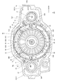
- the router main body 30 includes a housing 31 constituting the outer shell of the router main body 30, a motor 40 housed inside the housing 31, and a "holding member".
- the holding ring 60 and a pair of left and right handles 50 attached to the housing 31 are included.
- the housing 31 includes an end bracket 32 as a "second housing” forming the lower part of the housing 31 and a motor housing 33 as a "first housing” forming the upper part of the housing 31.
- the end bracket 32 is made of a metal material.
- the end bracket 32 is formed in a substantially rectangular parallelepiped box shape that is open upward and has a longitudinal direction in the left-right direction.
- the end bracket 32 has an integral structure and cannot be divided.
- a pair of connecting cylinders 32A are formed on both ends of the end bracket 32 in the left-right direction.
- the connecting cylinder portion 32A is formed in a substantially cylindrical shape with the vertical direction as the axial direction, and protrudes upward and downward from the bottom wall of the end bracket 32. Then, the column 21 described above is inserted into the connecting cylinder portion 32A so as to be relatively movable in the vertical direction.
- the fan accommodating portion 32B is formed in a substantially cylindrical shape and projects upward from the bottom wall of the end bracket 32.
- the end bracket 32 is formed with a substantially cylindrical support cylinder portion 32C inside the fan accommodating portion 32B in the radial direction.
- the support cylinder portion 32C is arranged coaxially with the fan accommodating portion 32B, and the inside of the support cylinder portion 32C penetrates in the vertical direction.
- a plurality of relief grooves 32D (see FIG.
- a plurality of exhaust holes 32E are formed between the fan accommodating portion 32B and the support cylinder portion 32C.
- the plurality of exhaust holes 32E are arranged side by side in the fan accommodating portion 32B along the circumferential direction.
- an illumination hole 32F is formed through in the vertical direction on the radial outer side of the fan accommodating portion 32B. There is.
- One illumination hole 32F is arranged diagonally to the right and rearward with respect to the axis AL of the support cylinder portion 32C, and the other illumination hole 32F is arranged obliquely rearward to the left with respect to the axis AL of the support cylinder portion 32C. There is.
- handle fixing portions 32G for fixing the handle 50 are formed at both ends of the end bracket 32 in the left-right direction.
- the handle fixing portion 32G is formed in a substantially columnar shape with the left-right direction as the axial direction, and projects outward from the end bracket 32 in the left-right direction.
- a cutout portion 32H (see cross section AA in FIG. 4) is formed on the outer peripheral portion of the handle fixing portion 32G on the right side, and the cutout portion 32H is open to the rear side and the upper side when viewed from the right side.
- a stopper portion 32J (see FIG. 4) projecting to the rear side is formed on the outer peripheral portion of the left end portion of the end bracket 32.
- the stopper portion 32J is formed in a substantially tubular shape in the vertical direction and the axial direction, and the bolt 22 described above inserts the inside of the stopper portion 32J. Then, the stopper portion 32J is in contact with the nut 23 provided at the upper end portion of the bolt 22 from below. As a result, the movement of the end bracket 32 (router main body 30) upward is restricted at the positions shown in FIGS. 1 and 2 (hereinafter, the position of the router main body 30 is referred to as an "initial position").
- the motor housing 33 is made of a resin material and is arranged adjacent to the upper side of the end bracket 32.
- the motor housing 33 is formed in a substantially rectangular box shape (cylindrical shape) that is open downward.
- the motor housing 33 is integrally formed, and cannot be divided in the front-rear direction or the left-right direction, for example. Further, the opening of the motor housing 33 is formed in a shape corresponding to the opening of the end bracket 32. Then, the motor housing 33 is fastened and fixed to the end bracket 32 so as to close the opening of the end bracket 32.
- a pair of left and right connecting shafts 35 are provided inside the motor housing 33 at positions corresponding to the columns 21 described above.
- the connecting shaft 35 is formed in a substantially columnar shape with the vertical direction as the axial direction, extends downward from the top wall of the motor housing 33, and is inserted into the column 21 so as to be relatively movable in the vertical direction.
- an urging spring 36 configured as a compression coil spring is extrapolated to the connecting shaft 35.
- the upper end of the urging spring 36 is locked to the top wall of the motor housing 33, and the lower end of the urging spring 36 is locked to the upper end of the column 21. (That is, the router body 30) is urged upward.
- the router main body 30 is held in the initial position.
- the router main body 30 is pushed downward against the urging force of the urging spring 36, so that the router main body 30 moves downward relative to the base 20.
- a motor accommodating portion 33A for accommodating the motor 40 is formed in the central portion in the left-right direction of the motor housing 33.
- the motor accommodating portion 33A is formed in a substantially bottomed cylindrical shape that is open downward, and is arranged coaxially with the fan accommodating portion 32B and the support cylinder portion 32C of the end bracket 32.
- Four guide ribs 33B extending in the vertical direction are formed on the side wall of the motor accommodating portion 33A.
- the guide ribs 33B project radially inward and outward from the side wall of the motor accommodating portion 33A, and the lower end portion of the guide rib 33B projects downward from the side wall of the motor accommodating portion 33A.
- one guide rib 33B is arranged diagonally to the left and rearward with respect to the axis AL of the motor accommodating portion 33A, and four guide ribs 33B are arranged every 90 degrees in the circumferential direction of the motor accommodating portion 33A. ing.
- a pair of front and rear right rotation restricting ribs 33C (see FIG. 7) extending in the vertical direction are formed at the right end of the inner peripheral surface of the motor accommodating portion 33A, and the pair of right front and rear rotation restricting ribs 33C are front and rear. They are arranged at predetermined intervals in the direction. Further, a pair of left side rotation restricting ribs 33D (see FIG. 7) extending in the vertical direction are formed at the left end portion of the inner peripheral surface of the motor accommodating portion 33A. Further, a pair of left and right axial regulation ribs 33E (see FIG. 5) are formed on the inner peripheral surface of the motor accommodating portion 33A.
- the axial regulation rib 33E extends from the top wall of the motor accommodating portion 33A to the vertical intermediate portion of the motor accommodating portion 33A.
- the right axial regulation rib 33E is arranged between the pair of right rotation regulation ribs 33C and connected to the pair of right rotation regulation ribs 33C.
- the left axial regulation rib 33E is arranged on the front side of the left rotation regulation rib 33D and is connected to the left rotation regulation rib 33D.
- the communication holes 33F are formed through the top wall of the motor accommodating portion 33A.
- the communication holes 33F are formed in a substantially fan shape in a plan view, and are arranged every 90 degrees in the circumferential direction of the motor accommodating portion 33A.
- a communication groove 33G open to the lower side is formed at the right end portion at the lower end portion of the motor housing 33, and the inside and the outside of the motor housing 33 are communicated by the communication groove 33G.
- the motor 40 is housed in the motor housing 33A of the motor housing 33.
- the motor 40 includes a rotating shaft 41 having an axial direction in the vertical direction, a substantially cylindrical rotor 42 fixed to the rotating shaft 41, and a substantially cylindrical stator 43 arranged radially outside the rotor 42. It is configured to include.
- the rotating shaft 41 is arranged coaxially with the motor accommodating portion 33A, and the lower end portion (one end portion on one side in the axial direction) of the rotating shaft 41 projects downward from the motor housing 33 to support the end bracket 32.
- the inside of the cylinder portion 32C is inserted. That is, the axis of the rotating shaft 41 coincides with the axis AL.
- the lower end of the rotating shaft 41 is rotatably supported by the bearing 34 of the end bracket 32, and the upper end of the rotating shaft 41 is rotatably supported by the bearing 37 fixed to the motor housing 33. .. Since the bearing 34 and the bearing 37 are held by the end bracket 32 and the motor housing 33, which have high rigidity because they are indivisible, the rotating shaft 41 can be supported with high accuracy.
- a tip tool 46 is attached to the lower end of the rotating shaft 41 via a collect chuck 45. As a result, the tip tool 46 is configured to insert the inside of the insertion portion 20A of the base 20 by pushing down the router main body 30 from the initial position.
- the stator 43 has a stator holder 44, and the stator holder 44 is formed in a substantially cylindrical shape.
- a stator coil (not shown) is wound around the stator holder 44, and the stator coil is connected to a motor substrate 40A provided at the upper end of the motor 40.
- a pair of left and right positioning ribs 44A are formed on the outer peripheral portion of the stator holder 44, and the positioning ribs 44A extend in the vertical direction.
- the guide ribs 33B of the motor housing 33 are arranged adjacent to the radial outer side of the stator holder 44 (see FIG. 7).
- the stator holder 44 (stator 43) is arranged coaxially with the rotating shaft 41.
- the right positioning rib 44A is inserted between the pair of right side rotation restricting ribs 33C in the motor housing 33, and the left side positioning rib 44A is arranged adjacent to the front side of the left side rotation restricting rib 33D of the motor housing 33. (See Fig. 7).
- the relative rotation of the stator 43 with respect to the motor housing 33 is regulated by the right side rotation restricting rib 33C, the left side rotation restricting rib 33D, and the positioning rib 44A.
- the positioning rib 44A is arranged adjacent to the lower side of the axial regulation rib 33E of the motor housing 33, and is arranged adjacent to the upper side of the holding ring 60 described later (see FIG. 5).
- the vertical movement of the stator 43 is restricted by the axial regulation rib 33E and the holding ring 60.
- a fan 47 is integrally rotatably provided at the lower end of the rotating shaft 41 under the rotor 42 and the stator 43. Specifically, the fan 47 is arranged on the upper side of the support cylinder portion 32C of the end bracket 32 and on the radial inner side of the upper portion of the fan accommodating portion 32B. Further, the upper portion of the fan 47 projects upward from the fan accommodating portion 32B.
- the fan 47 has a plurality of blades 47A. The blades 47A extend in the radial direction of the rotating shaft 41 and are arranged side by side in the rotating direction of the fan 47.
- the fan 47 is configured as a so-called axial flow fan, and when the fan 47 rotates, the air (cooling air) flowing in from the intake hole 80B described later cools the control unit 90, and then the control unit 90 is cooled.
- the motor 40 flows into the inside of the motor housing 33 from the upper opening of the motor housing 33, is rectified to the lower side of the fan 47, and flows out from the exhaust hole 32E to the lower side.
- the handle 50 is formed in a hollow substantially T-shape rotated by 90 degrees when viewed from the front.
- the handle 50 includes a substantially cylindrical mounting portion 50A whose axial direction is the left-right direction, and a grip portion 50B extending in the vertical direction from the lateral end portion in the left-right direction of the mounting portion 50A. It is configured.
- the handle 50 is divided into two in the left-right direction at the portion of the grip portion 50B, and is composed of two members.
- the handle 50 includes a handle body 51 that constitutes an inner portion in the left-right direction of the handle 50, and a handle cover 52 that forms an outer portion in the left-right direction of the handle 50.
- the handle fixing portion 32G of the end bracket 32 is inserted inside the mounting portion 50A, and the handle body 51 is fastened and fixed to the end bracket 32. Further, after the handle body 51 is fixed to the end bracket 32, the handle cover 52 is fastened and fixed to the handle body 51 with screws.
- the handle 50 on the right side is provided with a switch button 53 that can be pressed and operated at the upper part, and a trigger 54 that can be operated by pulling at the rear part. Further, inside the handle 50 on the right side, a switch circuit portion 55 that is operated by operating the switch button 53 and the trigger 54 is provided, and the switch circuit portion 55 is fixed to the handle main body 51.
- the switch circuit unit 55 has a switch (not shown) operated by a switch button 53 and a trigger 54. The switch is electrically connected to the control unit 90 described later, and is configured to output an output signal according to the operating state of the switch button 53 and the trigger 54 to the control unit 90 described later.
- the holding ring 60 is made of a transparent resin material having translucency.
- the holding ring 60 has a ring base 61 as a "base”.
- the ring base 61 is formed in a substantially ring shape (substantially cylindrical shape) with the vertical direction as the axial direction, and is formed in a substantially U shape open upward in a cross-sectional view seen from the circumferential direction. Has been done.
- the ring base 61 includes a substantially cylindrical inner cylinder 61A whose axial direction is the vertical direction, a cylindrical outer cylinder 61B arranged radially outside the inner cylinder 61A, and a lower end of the inner cylinder 61A. It is configured to include a bottom portion 61C that connects the portion and the lower end portion of the outer cylinder 61B. As a result, a guide groove 62 as a "groove portion" opened upward is formed inside the ring base 61.
- the ring base 61 is arranged inside the end bracket 32 on the outer side in the radial direction of the fan 47. Specifically, the bottom portion 61C of the ring base 61 is arranged adjacent to the upper side of the fan accommodating portion 32B of the end bracket 32, and the outer cylinder 61B of the ring base 61 is a part of the lower end portion of the motor housing 33. It is located adjacent to the lower side. As a result, the ring base 61 is sandwiched in the vertical direction by the end bracket 32 and the motor housing 33, and is fixed to both of them.
- the upper portion of the blade 47A of the fan 47 is arranged radially inside the lower portion of the inner cylinder 61A of the ring base 61.
- the air in the motor housing 33 is guided by the inner cylinder 61A of the holding ring 60 and flows to the fan 47 (blade 47A) side.
- a pair of left and right restricting portions 63 projecting upward are formed on the upper end surface of the inner cylinder 61A.
- the regulating portion 63 is arranged at a position corresponding to the positioning rib 44A of the stator 43, and the lower end of the positioning rib 44A is in contact with the upper end of the regulating portion 63 (see FIG. 5). As a result, the downward movement of the stator 43 is restricted by the holding ring 60.
- the guide recess 64 is formed in a concave shape that is open to the upper side, and is arranged at a position corresponding to the guide rib 33B of the motor housing 33. Then, the lower end portion of the guide rib 33B is inserted into the guide recess 64 (see FIGS. 5, 6, and 8). As a result, when the motor housing 33 is attached to the end bracket 32, the holding ring 60 is configured to guide the motor housing 33.
- the lower end portion of the guide rib 33B is configured to extend in the radial direction of the ring base 61 in the upper portion of the guide groove 62 of the holding ring 60. (See FIG. 8).
- the holding ring 60 has a holding pillar 65 as a pair of left and right "extending parts" for holding the lighting parts 70L and 70R described later.
- the holding column 65 is formed in a substantially rectangular columnar shape extending in the vertical direction. Further, the holding column 65 is arranged at a position corresponding to the illumination hole 32F of the end bracket 32 described above (see FIG. 8), and is arranged adjacent to the outer side in the radial direction of the ring base 61. Specifically, one holding column 65 is arranged diagonally to the right and rearward with respect to the axis AL of the rotating shaft 41 in a plan view, and the other holding column 65 is arranged diagonally rearward to the right with respect to the axis AL of the rotating shaft 41 in a plan view.
- the upper end of the holding column 65 is connected to the lower end of the outer cylinder 61B of the ring base 61, and the holding column 65 is integrally formed with the ring base 61. That is, the holding column 65 extends downward from the ring base 61. Specifically, the lower end of the holding column 65 is arranged below the fan 47. That is, the holding column 65 extends in the vertical direction on the radial outer side of the fan 47.
- the holding column 65 is tilted at approximately 45 degrees in a plan view, and the rear surface 65A of the holding column 65 is tilted to the rear side toward the right side in a plan view.
- the lighting accommodating portions 66 (FIGS. 11B and D) for accommodating the illumination portions 70L and 70R described later are accommodated. ) Is formed, and the illumination accommodating portion 66 is formed in a concave shape that is open to the rear side (specifically, in a direction orthogonal to the rear surface 65A). Further, a pair of wiring grooves 67 (see FIGS.
- the wiring grooves 67 extend in the vertical direction and are arranged side by side in the width direction of the holding columns 65.
- the upper end of the wiring groove 67 is open to the upper side, and the lower end of the wiring groove 67 communicates with the illumination accommodating portion 66.
- a lens portion 65B (in a broad sense, an element grasped as an "engaged portion") is formed at the lower end portion of the holding column 65.
- the lens portion 65B is formed in a substantially columnar shape with the vertical direction as the axial direction, and protrudes downward from the holding column 65. Then, the lens portion 65B is fitted in the illumination hole 32F of the end bracket 32. As a result, the lens portion 65B and the illumination hole 32F are engaged with each other around the axis AL, and the position of the holding ring 60 with respect to the end bracket 32 is determined.
- the ring base 61 is arranged coaxially with the rotating shaft 41.
- a pair of wiring slits 68L and 68R are formed in the outer cylinder 61B of the ring base 61 at positions corresponding to the pair of left and right holding columns 65.
- the pair of wiring slits 68L and 68R are formed through the outer cylinder 61B in the radial direction and are opened upward. As a result, the inside and the outside of the ring base 61 are communicated with each other by the wiring slits 68L and 68R.
- the reinforcing rib 69 is formed in a plate shape with the circumferential direction of the ring base 61 as the plate thickness direction, and is connected to the inner cylinder 61A, the bottom portion 61C, and the outer cylinder 61B.
- One reinforcing rib 69 is arranged at the rear end of the ring base 61, and four reinforcing ribs 69 are arranged at 90 degree intervals in the circumferential direction of the ring base 61.
- a wiring slit 69A is formed in the reinforcing rib 69.
- the wiring slit 69A is formed through the reinforcing rib 69 in the plate thickness direction and is open to the upper side.
- the lighting units 70L and 70R have a lighting substrate 71 and an LED 72 as a “light source”, respectively.
- the lighting substrate 71 is formed in a substantially rectangular plate shape with the vertical direction as the plate thickness direction, and is housed in the lighting accommodating portion 66 of the holding ring 60.
- the LED 72 is mounted on the lower surface of the lighting board 71 and is housed in the lighting housing portion 66 together with the lighting board 71.
- the LED 72 (illumination units 70L, 70R) is arranged below the fan 47.
- the LED 72 is configured to irradiate the emitted light downward. Specifically, the light emitted by the LED 72 passes through the lens portion 65B of the holding ring 60 and illuminates the lower side of the end bracket 32 from the illumination hole 32F of the end bracket 32. As a result, the light is used to illuminate the periphery of the tip tool 46. More specifically, the light emitted by the LED 72 is configured to illuminate the periphery of the tip tool 46 on the rear side of the tip tool 46 and on the outside in the left-right direction.
- two lead wires 73 as "wiring” extend from the lighting board 71, and the lead wire 73 is inside the wiring groove 67 of the holding column 65 on the left side in the holding ring 60. It is arranged in. Further, the lead wire 73 is inserted into the guide groove 62 of the ring base 61 from the left wiring slit 68L in the holding ring 60, is arranged in the rear portion of the guide groove 62, and is arranged from the right wiring slit 68R to the guide groove. It extends to the outside of 62.
- the lead wire 73 is inserted through the wiring slit 69A of the reinforcing rib 69 on the rear side, and extends from the wiring slit 68R on the right side to the outside of the guide groove 62. Further, in the arrangement state of the lead wire 73 into the guide groove 62, the lower end portion of the guide rib 33B of the motor housing 33 is arranged on the upper side of the lead wire 73, and the movement of the lead wire 73 to the upper side is restricted by the guide rib 33B. (See FIG. 8).
- one of the two lead wires 73 is arranged in the wiring groove 67 of one of the holding columns 65 on the right side, and is connected to the lighting board 71 of the lighting unit 70R on the right side.
- a lead wire 74 as "wiring” extends from the lighting board 71 of the lighting unit 70R on the right side, and the lead wire 74 is arranged in the other wiring groove 67 in the holding column 65 on the right side. ..
- the other lead wire 73 and the lead wire 74 are connected to the switch circuit portion 55 through the inside of the mounting portion 50A of the handle 50 on the right side.
- the lead wire 73 and the lead wire 74 are connected to the switch circuit portion 55 through the communication groove 33G of the motor housing 33 and the notch portion 32H of the handle fixing portion 32G in the end bracket 32.
- the battery holder 80 is provided on the upper side of the motor housing 33 and is formed in a substantially box shape open to the lower side.
- the battery holder 80 is divided into two in the front-rear direction. That is, the battery holder 80 includes a front holder 81 and a rear holder 82 that form a front portion of the battery holder 80, and the front holder 81 and the rear holder 82 are fastened to the motor housing 33. It is fixed.
- the battery holder 80 is formed with a battery mounting portion 80A for mounting the battery 85, which will be described later, and the battery mounting portion 80A is formed in a concave shape open to the upper side and the left side. Further, an intake hole 80B that functions as an inlet for an air flow generated by the rotation of the fan 47 is formed near the center of the battery holder 80 in the vertical direction. Specifically, an intake hole 80B is formed in the front side wall of the front holder 81 and the rear side wall of the rear holder 82. Further, the battery holder 80 is provided with a connector 83 (see FIG. 3), and the upper portion of the connector 83 is exposed inside the battery mounting portion 80A so as to be connectable to the battery 85 described later.
- Battery 85 is formed in a substantially rectangular parallelepiped. Then, the battery 85 is attached to the battery mounting portion 80A of the battery holder 80 from the left side.
- the battery 85 has a connector (not shown), and when the battery 85 is attached to the battery mounting portion 80A, the connector is connected to the connector 83 and power is supplied to the control unit 90 described later. ing. Further, the battery 85 has a pair of lock members 86, and the lock members 86 are provided on the front and rear side portions of the battery 85. When the battery 85 is mounted on the battery mounting portion 80A, the lock member 86 engages with the battery holder 80 to maintain the mounted state of the battery 85.
- control unit 90 As shown in FIG. 3, the control unit 90 is housed inside the battery holder 80 and fixed to the battery holder 80.
- the control unit 90 has a control board (not shown), and the motor 40 and the connector 83 described above are electrically connected to the control board.
- a lead wire (not shown) extending from the motor board 40A is connected to the control board through the communication hole 33F of the motor housing 33.
- a lead wire (not shown) extending from the control board is connected to the switch circuit unit 55, and the control unit 90 and the switch circuit unit 55 are electrically connected.
- the lead wire is arranged in the motor housing 33 on the radial outer side of the motor housing portion 33A, and in the communication groove 33G of the motor housing 33 and in the notch 32H of the handle fixing portion 32G in the end bracket 32. Is inserted and connected to the switch circuit unit 55. As a result, the control unit 90 and the lighting units 70L and 70R are electrically connected. Then, the control unit 90 is configured to turn on or off the LED 72 according to the on / off operation of the switch button 53. Further, the control unit 90 controls the operation of the motor 40 by operating the trigger 54 while the switch button 53 is on.
- the router 10 configured as described above includes lighting units 70L and 70R having an LED 72.
- the illumination units 70L and 70R are housed in the illumination accommodating unit 66 of the holding ring 60 and are held by the holding ring 60. Then, when the operator grips the grip portion 50B of the handle 50 and turns on the switch button 53, the power of the battery 85 is supplied to the LED 72 by the control unit 90, and the LED 72 emits light.
- the light emitted by the LED 72 passes through the lens portion 65B of the holding ring 60 and irradiates downward from the illumination hole 32F of the end bracket 32 to illuminate the periphery of the tip tool 46. Specifically, the lateral and rear portions of the tip tool 46 in the left-right direction are illuminated.
- the rotating shaft 41 of the motor 40 rotates together with the tip tool 46 under the control of the control unit 90.
- the router main body 30 moves downward relative to the base 20.
- the tip tool 46 comes into contact with the material to be cut, and the material to be cut is cut.
- the operator cuts the material to be cut while moving the router 10 to the rear side.
- the portion of the router 10 on the moving direction side of the tip tool 46 is illuminated by the LED 72.
- the visibility around the tip tool 46 can be improved during cutting. Therefore, the workability for the worker can be improved.
- a holding ring 60 for holding the illumination units 70L and 70R is provided below the stator 43 of the motor 40. Then, the regulating portion 63 of the holding ring 60 is arranged adjacent to the lower side of the positioning rib 44A of the stator 43 to restrict the movement of the stator 43 to the lower side. That is, the holding ring 60 has two functions, that is, a function of holding the illumination units 70L and 70R and a function of restricting the downward movement of the stator 43. In other words, the illumination units 70L and 70R can be held by utilizing the holding ring 60 that regulates the downward movement of the stator 43.
- the members for holding the illumination units 70L and 70R and the members for restricting the downward movement of the stator 43 can be used as a common member, and the illumination units 70L and 70R can be mounted on the router 10.
- the surroundings of the tip tool 46 can be illuminated by the illuminating units 70L and 70R while suppressing an increase in the number of parts.
- the upper portion of the fan 47 is arranged radially inside the lower portion of the ring base 61 in the holding ring 60.
- the air on the upper side of the fan 47 can be guided by the inner cylinder 61A of the ring base 61 and guided to the blade 47A side of the fan 47. Therefore, the air in the motor housing 33 can be efficiently guided to the fan 47 by utilizing the holding ring 60 that regulates the downward movement of the stator 43.
- the bottom portion 61C of the ring base 61 is arranged adjacent to the upper side of the fan accommodating portion 32B of the end bracket 32, and the outer cylinder 61B of the ring base 61 is located at the lower end portion of the motor housing 33. It is located adjacent to a part of the lower side.
- the ring base 61 is sandwiched in the vertical direction by the end bracket 32 and the motor housing 33, and is fixed to both of them. Therefore, additional parts for fixing are not required, and the holding ring 60 can be fixed to the end bracket 32 and the motor housing 33 with a simple configuration while maintaining the integrated structure of the end bracket 32 and the motor housing 33.
- a pair of lens portions 65B are formed in the holding ring 60, and the pair of lens portions 65B are fitted into the illumination holes 32F of the end bracket 32.
- the holding ring 60 and the end bracket 32 can be engaged with each other around the axis AL of the rotating shaft 41 to determine the position of the holding ring 60 with respect to the end bracket 32.
- the position of the holding ring 60 with respect to the end bracket 32 can be determined while restricting the rotation of the rotating shaft 41 around the axis AL of the holding ring 60.
- the holding ring 60 can be temporarily fixed to the end bracket 32, the motor housing 33 can be assembled to the end bracket 32, and the holding ring 60 can be fixed by the end bracket 32 and the motor housing 33. Therefore, the assembling property of the motor housing 33 to the end bracket 32 can be improved.
- the holding ring 60 includes a ring base 61 arranged between the motor 40 (rotor 42 and the stator 43) and the fan 47, and a holding pillar 65 extending downward from the ring base 61. It is configured.
- the lighting units 70L and 70R are housed in the lighting storage unit 66 formed at the lower end of the holding pillar 65. As a result, the LED 72 of the lighting units 70L and 70R can be held at a position close to the tip tool 46 by the holding pillar 65 while the ring base 61 restricts the movement of the stator 43 to the lower side. Therefore, the lighting effect of the lighting units 70L and 70R on the periphery of the tip tool 46 can be enhanced.
- a holding pillar 65 extending downward is formed and a holding ring 60 is formed.
- the illumination units 70L and 70R (illumination accommodating unit 66) are arranged below the fan 47, and the holding pillar 65 of the holding ring 60 is formed with a wiring groove 67 extending in the vertical direction. ing. Then, the lead wires 73 and 74 extending from the lighting units 70L and 70R are arranged in the wiring groove 67. That is, on the radial outer side of the fan 47, the holding column 65 extends in the vertical direction, and the lead wires 73 and 74 are held by the holding column 65. As a result, the lighting units 70L and 70R can be arranged at a position close to the tip tool 46 while suppressing the lead wires 73 and 74 extending from the lighting units 70L and 70R from moving toward the fan 47. ..
- the ring base 61 of the holding ring 60 is formed in a ring shape, and the ring base 61 has a guide groove 62 extending over the entire circumference in the circumferential direction.
- a lead wire 73 extending from the lighting unit 70L is arranged in the guide groove 62.
- the lead wire 73 for supplying electric power to the lighting unit 70L is suppressed by the ring base 61 (guide groove 62) from moving toward the fan 47, and the lead wire 73 is arranged around the fan 47. be able to.
- the holding ring 60 is provided with a pair of illumination units 70L and 70R, and the illumination units 70L and 70R are connected by a lead wire 73 arranged in the guide groove 62. Therefore, while suppressing the movement of the lead wire 73 toward the fan 47 by the ring base 61 (guide groove 62), the pair of illumination units 70L and 70R arranged around the fan 47 are connected by the lead wire 73. can do. In other words, it is possible to prevent the position of the lead wire 73 from deviating from a desired position during assembly or driving.
- the ring base 61 of the holding ring 60 is formed with reinforcing ribs 69 inside the guide groove 62, and the reinforcing ribs 69 are connected to the inner cylinder 61A, the outer cylinder 61B, and the bottom 61C of the ring base 61. ing.
- the reinforcing rib 69 is formed with a wiring slit 69A penetrating in the circumferential direction of the guide groove 62, and the lead wire 73 arranged in the guide groove 62 is inserted into the wiring slit 69A. Thereby, the lead wire 73 in the guide groove 62 can be held while the ring base 61 is reinforced by the reinforcing rib 69.
- a guide recess 64 is formed in the inner cylinder 61A of the holding ring 60.
- the guide rib 33B of the motor housing 33 is inserted into the guide recess 64 and is arranged above the guide groove 62 of the ring base 61. Therefore, the guide rib 33B of the motor housing 33 can limit the upward movement of the lead wire 73 arranged in the guide groove 62. As a result, it is possible to prevent the lead wire 73 from coming out of the opening of the guide groove 62 by utilizing the guide rib 33B for determining the position of the stator 43 with respect to the motor housing 33. Therefore, it is possible to maintain a better arrangement state of the lead wire 73 in the guide groove 62.
- the fan 47 is configured as a so-called axial fan, but the fan 47 may be configured as a so-called centrifugal fan. In this case, the air flow generated by the fan 47 may be configured to be rectified by the holding ring 60.
- the configuration when the fan 47 is a centrifugal fan will be described with reference to FIGS. 12A and 12B.
- the fan 47 when the fan 47 is configured as a centrifugal fan, the blades 47A of the fan 47 are arranged radially inside the lower end of the inner cylinder 61A in the holding ring 60. Further, a guide inclined portion 60A is formed at the lower end portion of the inner cylinder 61A, and the guide inclined portion 60A is viewed in cross section from the circumferential direction of the ring base 61 as it goes outward in the radial direction of the ring base 61. It is tilted downward.
- a guide piece 60B is formed on the bottom portion 61C of the ring base 61 on the radial outer side of the ring base 61 with respect to the guide inclined portion 60A, and the guide piece 60B extends downward from the bottom portion 61C. It is formed in a substantially cylindrical shape.
- the fan 47 Since the fan 47 is configured as a centrifugal fan, the fan 47 generates an air flow AC that flows from the center side of the fan 47 to the outside in the radial direction. At this time, since the opening on the upper side (downstream side of the air flow AC) of the holding ring 60 is opened with a diameter smaller than the outer diameter of the fan 47 (blade 47A), air can be efficiently collected on the rotation shaft 41 side. It is possible to smoothly guide the flow of the air flow AC flowing from the center side to the outside in the radial direction. Further, the air flow AC flowing outward in the radial direction of the fan 47 is rectified by the guide inclined portion 60A, and the direction of the air flow AC is changed to the lower side.
- the air flow AC changed to the downward flow by the guide inclined portion 60A is guided by the guide piece 60B and flows downward from the holding ring 60. Then, the air flow AC flowing downward from the holding ring 60 flows downward from the exhaust hole 32E of the end bracket 32.
- the air flow AC generated by the fan 47 can be rectified by the holding ring 60 and flowed out from the exhaust hole 32E of the end bracket 32. Therefore, the air flow AC generated by the fan 47 can be rectified by utilizing the holding ring 60 that holds the illumination units 70L and 70R and regulates the downward movement of the stator 43. Therefore, it is not necessary to separately provide a member for rectifying the air flow AC, so that an increase in the number of parts can be suppressed more effectively.
- the regulating portion 63 is omitted in the holding ring 60 and the air flow AC is moved to the lower side of the stator 43. Movement may be regulated by other members. For example, the downward movement of the stator 43 may be restricted by the end bracket 32.
- the lighting accommodating portion 66 is formed at the lower end portion of the holding pillar 65, but the vertical position of the illumination accommodating portion 66 can be arbitrarily changed. That is, the positions of the illumination units 70L and 70R in the vertical direction can be arbitrarily changed.
- the illumination unit 70R (illumination unit 70L) may be configured to be held at the upper end of the holding column 65.
- the illumination accommodating portion 66 is formed at the upper end portion of the holding column 65, and is formed in a concave shape that is open upward.
- the wiring groove 67 is omitted.
- the illumination unit 70R (illumination unit 70L) is accommodated in the illumination accommodating unit 66 from above and is held by the holding pillar 65. Further, in this case, the light emitted by the LED 72 of the illumination unit 70R (illumination unit 70L) (see the arrow indicated by the alternate long and short dash line in FIG.
- the holding column 65 including the lens portion 65B functions as a light guide portion that guides the light emitted by the LED 72 downward, and can guide the light to the lower side of the fan 47. Then, the light can be irradiated downward from the illumination hole 32F of the end bracket 32 to illuminate the periphery of the tip tool 46. Further, in this case, it is not necessary to arrange the lead wires 73 and 74 in the wiring groove 67 of the holding column 65. Therefore, it is possible to reduce the assembling man-hours when assembling the lighting units 70L and 70R to the holding ring 60.
- the lead wire 73 flutters, that is, the position. The same effect as that of the guide groove 62 that the deviation can be suppressed can be obtained.
- the pair of lighting units 70L and 70R are held by the holding ring 60, but the number of lighting members held by the holding ring 60 may be arbitrarily set. That is, the number of lighting members held by the holding ring 60 may be one or three or more.
- the router has been described as an embodiment of the present invention, the present invention can be applied to various other working machines. In particular, it can be applied to a work machine in which a fan is located between a tip tool and a motor, and can be applied to a work machine such as a disc grinder or a jigsaw, for example.
Landscapes
- Engineering & Computer Science (AREA)
- Mechanical Engineering (AREA)
- Life Sciences & Earth Sciences (AREA)
- General Engineering & Computer Science (AREA)
- Wood Science & Technology (AREA)
- Forests & Forestry (AREA)
- Details Of Spanners, Wrenches, And Screw Drivers And Accessories (AREA)
Abstract
部品点数の増加を抑制しつつ、先端工具の周囲を照明する。ルータ10は、LEDを有する照明部を備えており、照明部は、保持リング60の照明収容部に収容されて保持リング60に保持されている。ここで、保持リング60の規制部63が、ステータ43の位置決めリブ44Aの下側に隣接して配置されて、ステータ43の下側への移動を規制している。これにより、ステータ43の下側への移動を規制する保持リング60を活用して、照明部を保持することができる。したがって、照明部を保持する部材と、ステータ43の下側への移動を規制する部材とを共通部材にして、照明部をルータ10に搭載することができる。以上により、部品点数の増加を抑制しつつ、先端工具46の周囲を照明部によって照明することができる。
Description
本発明は、作業機に関するものである。
下記特許文献1には、モータの駆動によって先端工具が回転することで、被切削材に対して切削作業を施すルータ(作業機)が開示されている。具体的には、作業者が、ルータのハンドルを把持して、ルータを下側へ押下げることで、先端工具が被切削材に当接して、被切削材に対して切削作業が施される。また、ルータでは、切削加工時における作業性を向上するために、先端工具の周囲を照明する照明部を設けたものもある。
ここで、上記特許文献1に記載のルータに、照明部を搭載する場合には、照明部を保持するための部材等を別途設ける必要がある。このため、部品点数の増加等を招く可能性がある。したがって、ルータに照明部を搭載する場合には、部品点数の増加を抑制しつつ、先端工具の周囲を照明できる構造にすることが望ましい。また、照明部を搭載する場合には、組み立て性の悪化を抑制することが望ましい。
本発明は、上記事実を考慮して、部品点数の増加を抑制しつつ、先端工具の周囲を照明することができる作業機を提供することを目的とする。また、別の目的として、組み立て性の悪化を抑制しながら先端工具の周囲を照明することができる作業機を提供することを目的とする。
本発明の1又はそれ以上の実施形態は、回転軸と、前記回転軸に一体回転可能に構成されたロータと、前記ロータの径方向外側に配置されたステータと、を含んで構成されたモータと、前記回転軸に設けられ、前記ロータ及び前記ステータに対して前記回転軸の軸方向一方側に配置されたファンと、前記モータを収容するハウジングと、前記回転軸の軸方向一端部に取付けられた先端工具と、発光された光を前記先端工具の周囲へ向けて照射する光源を含んで構成された照明部と、前記ファンの径方向外側に設けられ、前記ファンによって生成された空気流を整流すると共に、前記照明部を保持する保持部材と、を備えた作業機である。
本発明の1又はそれ以上の実施形態は、回転軸と、前記回転軸に一体回転可能に構成されたロータと、前記ロータの径方向外側に配置されたステータと、を含んで構成されたモータと、前記モータを収容するハウジングと、前記回転軸に設けられ、前記ロータ及び前記ステータに対して前記回転軸の軸方向一方側に配置されたファンと、前記回転軸の軸方向一端部に取付けられた先端工具と、発光された光を前記先端工具の周囲へ向けて照射する光源を含んで構成された照明部と、前記ステータに対して前記回転軸の軸方向一方側に設けられ、前記照明部を保持すると共に、前記ステータにおける前記回転軸の軸方向一方側への移動を規制する保持部材と、を備えた作業機である。
本発明の1又はそれ以上の実施形態は、前記ハウジングは、前記モータを収容する第1ハウジングと、前記第1ハウジングに対して前記回転軸の軸方向一方側に設けられた第2ハウジングと、を含んで構成されており、前記保持部材が、前記回転軸の軸方向において、前記第1ハウジングと前記第2ハウジングとによって挟持されている作業機である。
本発明の1又はそれ以上の実施形態は、前記第2ハウジングには、前記保持部材と係合された係合部が形成されており、前記回転軸の周方向における前記保持部材の回転が前記係合部によって規制されている作業機である。
本発明の1又はそれ以上の実施形態は、前記保持部材は、前記ロータ及び前記ステータと前記ファンとの間に配置された基部と、前記基部から前記回転軸の軸方向一方側へ延出された延出部と、を含んで構成されており、前記照明部が、前記延出部の先端部に保持されている作業機である。
本発明の1又はそれ以上の実施形態は、前記保持部材は、前記ロータ及び前記ステータと前記ファンとの間に配置された基部と、前記基部から前記回転軸の軸方向一方側へ延出された延出部と、を含んで構成されており、前記照明部が、前記延出部の基端部に保持され、前記延出部が前記光源によって発光された光を透過して、当該光が前記延出部の先端部から前記先端工具の周囲へ向けて照射される作業機である。
本発明の1又はそれ以上の実施形態は、前記基部には、前記回転軸の軸方向他方側へ開放された溝部が形成されており、前記照明部と接続された配線が、前記溝部内に配策されている作業機である。
本発明の1又はそれ以上の実施形態は、前記保持部材には、一対の前記照明部が保持されており、一対の前記照明部を接続する配線が前記溝部内に配策されている作業機である。
本発明の1又はそれ以上の実施形態は、前記ハウジングに対して前記回転軸の軸方向他方側には、分割ハウジングが設けられており、前記分割ハウジングが、前記回転軸の軸方向に対して直交する方向に分割可能に構成されている作業機である。
本発明の1又はそれ以上の実施形態は、前記分割ハウジングには、前記照明部の点灯及び消灯を制御する制御部が設けられている作業機である。
本発明の1又はそれ以上の実施形態は、前記分割ハウジングには、前記照明部に電力を供給する電池が着脱可能に設けられている作業機である。
本発明の1又はそれ以上の実施形態は、回転軸と、前記回転軸に一体回転可能に構成されたロータと、前記ロータの径方向外側に配置されたステータと、を含んで構成されたモータと、前記回転軸に設けられ、前記ロータ及び前記ステータに対して前記回転軸の軸方向一方側に配置されたファンと、前記モータを収容するハウジングと、前記回転軸の軸方向一端部に取付けられた先端工具と、発光された光を前記先端工具の周囲へ向けて照射する光源を含んで構成された照明部と、前記照明部を保持する保持部材と、を備え、前記保持部材は、前記ロータ及び前記ステータと前記ファンとの間に配置された基部と、前記基部から前記回転軸の軸方向一方側へ延出され、前記照明部を保持すると共に、前記光源によって発光された光を透過し且つ先端部から当該光を前記先端工具の周囲へ向けて照射する延出部と、を含んで構成されており、前記延出部の先端部が、前記ファンよりも前記回転軸の軸方向一方側に配置されている作業機である。
上記構成の作業機によれば、部品点数の増加を抑制しつつ、先端工具の周囲を照明することができる。
以下、図面を用いて、本実施形態に係る「作業機」としてのルータ10について説明する。なお、図面において適宜示される矢印UP、矢印FR、及び矢印RHは、それぞれルータ10の上側、前側、及び右側を示している。そして、以下の説明において、上下、前後、左右の方向を用いて説明するときには、特に断りのない限り、ルータ10の上下方向、前後方向、左右方向を示すものとする。
ルータ10は、被切削材の上側に載置されて、当該被切削材に切削加工を施す工具として構成されている。図1及び図2に示されるように、ルータ10は、ベース20と、ルータ本体30と、一対の照明部70L,70R(図8参照)と、「分割ハウジング」としてのバッテリーホルダ80と、「電池」としてのバッテリー85と、制御部90(図5参照)と、を含んで構成されている。以下、ルータ10の各構成について説明する。
(ベース20について) 図1~図3に示されるように、ベース20は、ルータ10の下端部を構成すると共に、上下方向を板厚方向とした略円板状に形成されている。ベース20の略中央部には、挿通部20Aが上下方向に貫通形成されている。
ベース20の左右方向両端部には、一対のコラム21が設けられており、コラム21は、上下方向を軸方向とする略円筒状に形成されている。コラム21の下端部は、ベース20に固定されており、コラム21が、ベース20から上側へ延出している。
ベース20には、左側のコラム21の後側において、上下方向に延在されたボルト22が設けられている。ボルト22の下端部は、ベース20に固定されており、ボルト22が、ベース20から上側へ延出している。また、ボルト22の上端部には、ナット23(図3参照)が螺合されている。
(ルータ本体30について) 図1~図8に示されるように、ルータ本体30は、ルータ本体30の外郭を構成するハウジング31と、ハウジング31の内部に収容されたモータ40及び「保持部材」としての保持リング60と、ハウジング31に取付けられた左右一対のハンドル50と、を含んで構成されている。また、ハウジング31は、ハウジング31の下部を構成する「第2ハウジング」としてのエンドブラケット32と、ハウジング31の上部を構成する「第1ハウジング」としてのモータハウジング33と、を含んで構成されている。以下、ルータ本体30の各構成について説明する。
<エンドブラケット32について> エンドブラケット32は、金属材によって構成されている。エンドブラケット32は、上側へ開放され且つ左右方向を長手方向とする略直方体箱状に形成されている。エンドブラケット32は一体構造とされており、分割することはできない。エンドブラケット32の左右方向両端側部分には、一対の連結筒部32Aが形成されている。連結筒部32Aは、上下方向を軸方向とした略円筒状に形成されると共に、エンドブラケット32の底壁から上側及び下側へ突出している。そして、前述したコラム21が、連結筒部32Aの内部に上下方向に相対移動可能に挿入されている。
エンドブラケット32の左右方向中央部には、一対の連結筒部32Aの間において、後述するファン47を収容するためのファン収容部32Bが形成されている。ファン収容部32Bは、略円筒状に形成されて、エンドブラケット32の底壁から上側へ突出している。また、エンドブラケット32には、ファン収容部32Bの径方向内側において、略円筒状の支持筒部32Cが形成されている。支持筒部32Cは、ファン収容部32Bと同軸上に配置されており、支持筒部32Cの内部が、上下方向に貫通している。支持筒部32Cには、下側へ開放された複数の逃げ溝32D(図5参照)が形成されており、逃げ溝32Dは、支持筒部32Cの周方向に沿って並んで配置されている。さらに、支持筒部32Cの径方向内側には、後述するモータ40の回転軸41を支持するための軸受34が設けられている。
また、エンドブラケット32の底壁には、ファン収容部32Bと支持筒部32Cとの間において、複数の排気孔32E(図4参照)が形成されている。複数の排気孔32Eは、ファン収容部32Bに周方向に沿って並んで配置されている。さらに、エンドブラケット32の底壁には、ファン収容部32Bの径方向外側において、円形状の左右一対の「係合部」としての照明孔32F(図4参照)が上下方向に貫通形成されている。一方の照明孔32Fは、支持筒部32Cの軸線ALに対して右斜め後方に配置されており、他方の照明孔32Fは、支持筒部32Cの軸線ALに対して左斜め後方に配置されている。
また、エンドブラケット32の左右方向両端部には、後述するハンドル50を固定するためのハンドル固定部32Gが形成されている。ハンドル固定部32Gは、左右方向を軸方向とする略円柱状に形成されて、エンドブラケット32から左右方向外側へ突出している。右側のハンドル固定部32Gの外周部には、切欠部32H(図4の断面AA参照)が形成されており、切欠部32Hは、右側から見て、後側及び上側へ開放されている。
また、エンドブラケット32の左端部の外周部には、後側へ突出したストッパ部32J(図4参照)が形成されている。ストッパ部32Jは、上下方向と軸方向とする略筒状に形成されており、前述したボルト22が、ストッパ部32Jの内部を挿通している。そして、ボルト22の上端部に設けられたナット23にストッパ部32Jが下側から当接している。これにより、図1及び図2に示される位置において、エンドブラケット32(ルータ本体30)の上側への移動が規制されている(以下、このルータ本体30の位置を「初期位置」という)。
<モータハウジング33について> モータハウジング33は、樹脂材によって構成されると共に、エンドブラケット32の上側に隣接して配置されている。モータハウジング33は、下側へ開放された略矩形箱状(筒状)に形成されている。モータハウジング33は一体的に形成されており、例えば前後方向や左右方向に分割することはできない。また、モータハウジング33の開口部は、エンドブラケット32の開口部に対応する形状に形成されている。そして、モータハウジング33が、エンドブラケット32の開口部を閉塞するように、エンドブラケット32に締結固定されている。
図5に示されるように、モータハウジング33の内部には、前述したコラム21に対応する位置において、左右一対の連結軸35が設けられている。連結軸35は、上下方向を軸方向とする略円柱状に形成され、モータハウジング33の頂壁から下側へ延出されると共に、コラム21内に上下方向に相対移動可能に挿入されている。また、連結軸35には、圧縮コイルスプリングとして構成された付勢バネ36が外挿されている。付勢バネ36の上端部は、モータハウジング33の頂壁に係止され、付勢バネ36の下端部は、コラム21の上端部に係止されており、付勢バネ36によって、モータハウジング33(すなわち、ルータ本体30)が上側へ付勢されている。これにより、ルータ本体30が、初期位置に保持されている。そして、付勢バネ36の付勢力に抗してルータ本体30を下側へ押下げることで、ルータ本体30がベース20に対して下側へ相対移動する構成になっている。
図3、図5、及び図7に示されるように、モータハウジング33の左右方向中央部には、後述するモータ40を収容するためのモータ収容部33Aが形成されている。モータ収容部33Aは、下側へ開放された略有底円筒状に形成されると共に、エンドブラケット32のファン収容部32B及び支持筒部32Cと同軸上に配置されている。モータ収容部33Aの側壁には、上下方向に延在された4箇所のガイドリブ33Bが形成されている。ガイドリブ33Bは、モータ収容部33Aの側壁から径方向内側及び外側にそれぞれ突出しており、ガイドリブ33Bの下端部が、モータ収容部33Aの側壁よりも下側へ突出している。また、1箇所のガイドリブ33Bが、モータ収容部33Aの軸線ALに対して、左斜め後方に配置されており、4箇所のガイドリブ33Bは、モータ収容部33Aの周方向に90度毎に配置されている。
モータ収容部33Aの内周面の右端部には、上下方向に延在された前後一対の右側回転規制リブ33C(図7参照)が形成されており、一対の右側回転規制リブ33Cは、前後方向に所定の間隔を空けて配置されている。また、モータ収容部33Aの内周面の左端部には、上下方向に延在された一対の左側回転規制リブ33D(図7参照)が形成されている。さらに、モータ収容部33Aの内周面には、左右一対の軸方向規制リブ33E(図5参照)が形成されている。軸方向規制リブ33Eは、モータ収容部33Aの頂壁からモータ収容部33Aの上下方向中間部まで延出されている。そして、右側の軸方向規制リブ33Eが、一対の右側回転規制リブ33Cの間に配置され、一対の右側回転規制リブ33Cに接続されている。また、左側の軸方向規制リブ33Eが、左側回転規制リブ33Dの前側に配置されて、左側回転規制リブ33Dに接続されている。
図3に示されるように、モータ収容部33Aの頂壁には、4箇所の連通孔33Fが貫通形成されている。連通孔33Fは、平面視で略扇形状に形成されて、モータ収容部33Aの周方向に90度毎に配置されている。さらに、モータハウジング33の下端部における右端部には、下側へ開放された連通溝33Gが形成されており、連通溝33Gによってモータハウジング33の内部と外部とが連通されている。
<モータ40について> 図3、図5、及び図7に示されるように、モータ40は、モータハウジング33のモータ収容部33A内に収容されている。モータ40は、上下方向を軸方向とする回転軸41と、回転軸41に固定された略円筒状のロータ42と、ロータ42の径方向外側に配置された略円筒状のステータ43と、を含んで構成されている。
回転軸41は、モータ収容部33Aと同軸上に配置されており、回転軸41の下端部(軸方向一方側の端部)が、モータハウジング33から下側へ突出して、エンドブラケット32の支持筒部32C内を挿通している。すなわち、回転軸41の軸線が、軸線ALと一致している。そして、回転軸41の下端部が、エンドブラケット32の軸受34に回転可能に支持されており、回転軸41の上端部が、モータハウジング33に固定された軸受37に回転可能に支持されている。軸受34と軸受37とは、分割不能に構成されることで高い剛性を有するエンドブラケット32とモータハウジング33のそれぞれに保持されているため、回転軸41を精度よく支持することができる。また、回転軸41の下端部には、コレクトチャック45を介して先端工具46が取付けられている。これにより、ルータ本体30を初期位置から下側へ押下げることで、先端工具46が、ベース20の挿通部20A内を挿通するように構成されている。
ステータ43は、ステータホルダ44を有しており、ステータホルダ44は略円筒状に形成されている。ステータホルダ44には、図示しないステータコイル(図示省略)が巻き回されており、ステータコイルは、モータ40の上端部に設けられたモータ基板40Aに接続されている。ステータホルダ44の外周部には、左右一対の位置決めリブ44Aが形成されており、位置決めリブ44Aは、上下方向に延在されている。
そして、モータ40のモータ収容部33A内への収容状態では、モータハウジング33のガイドリブ33Bが、ステータホルダ44の径方向外側に隣接して配置されている(図7参照)。これにより、ステータホルダ44(ステータ43)が、回転軸41と同軸上に配置されている。また、右側の位置決めリブ44Aが、モータハウジング33における一対の右側回転規制リブ33Cの間に挿入され、左側の位置決めリブ44Aが、モータハウジング33の左側回転規制リブ33Dの前側に隣接して配置されている(図7参照)。これにより、右側回転規制リブ33C及び左側回転規制リブ33Dと、位置決めリブ44Aと、によって、ステータ43のモータハウジング33に対する相対回転が規制されている。また、位置決めリブ44Aは、モータハウジング33の軸方向規制リブ33Eの下側に隣接して配置されると共に、後述する保持リング60の上側に隣接して配置されている(図5参照)。これにより、軸方向規制リブ33E及び保持リング60によって、ステータ43の上下方向の移動が規制されている。
図3、図5、図6、及び図8に示されるように、回転軸41の下端部には、ロータ42及びステータ43の下側において、ファン47が一体回転可能に設けられている。具体的には、ファン47は、エンドブラケット32の支持筒部32Cの上側で且つファン収容部32Bの上部の径方向内側に配置されている。また、ファン47の上部は、ファン収容部32Bから上側へ突出している。ファン47は、複数の羽根47Aを有している。羽根47Aは、回転軸41の径方向に延在されと共に、ファン47の回転方向に並んで配置されている。また、本実施の形態では、ファン47が、所謂軸流ファンとして構成されており、ファン47が回転すると、後述する吸気孔80Bから流入した空気(冷却風)が制御部90を冷却したのち、モータハウジング33の上側開口からモータハウジング33の内部に流れこんでモータ40を冷却し、ファン47の下側へ整流されて、排気孔32Eから下側へ流出される構成になっている。
<ハンドル50について> 図1、図2、及び図5に示されるように、ハンドル50は、正面視で、90度回転させた中空の略T字形状に形成されている。具体的には、ハンドル50は、左右方向を軸方向とする略円筒状の取付部50Aと、取付部50Aの左右方向外側端部から上下方向に延出された把持部50Bと、を含んで構成されている。また、ハンドル50は、把持部50Bの部分において左右方向に2分割されて、2つの部材で構成されている。具体的には、ハンドル50は、ハンドル50の左右方向内側部分を構成するハンドル本体51と、ハンドル50の左右方向外側部分を構成するハンドルカバー52と、を含んで構成されている。そして、エンドブラケット32のハンドル固定部32Gが取付部50Aの内部に内挿されて、ハンドル本体51が、エンドブラケット32に締結固定されている。さらに、ハンドル本体51のエンドブラケット32への固定後に、ハンドルカバー52がネジによってハンドル本体51に締結固定されている。
右側のハンドル50には、上部において、スイッチボタン53が押圧操作可能に設けられており、後部において、トリガ54が引き操作可能に設けられている。さらに、右側のハンドル50の内部には、スイッチボタン53及びトリガ54の操作によって作動するスイッチ回路部55が設けられており、スイッチ回路部55は、ハンドル本体51に固定されている。スイッチ回路部55は、スイッチボタン53及びトリガ54によって操作される、図示しないスイッチを有している。当該スイッチは、後述する制御部90に電気的に接続されており、スイッチボタン53及びトリガ54の操作状態に応じた出力信号を、後述する制御部90に出力する構成になっている。
<保持リング60について> 図5、図6、及び図8~図11に示されるように、保持リング60は、透光性を有する透明の樹脂材によって構成されている。保持リング60は、「基部」としてのリングベース61を有している。リングベース61は、全体として、上下方向を軸方向とした略リング状(略円筒状)に形成されると共に、その周方向から見た断面視で、上側へ開放された略U字形状に形成されている。具体的には、リングベース61は、上下方向を軸方向とする略円筒状の内筒61Aと、内筒61Aの径方向外側に配置された円筒状の外筒61Bと、内筒61Aの下端部及び外筒61Bの下端部を接続する底部61Cと、を含んで構成されている。これにより、リングベース61の内部には、上側へ開放された「溝部」としてのガイド溝62が形成されている。
そして、リングベース61が、エンドブラケット32の内部において、ファン47の径方向外側に配置されている。具体的には、リングベース61の底部61Cが、エンドブラケット32のファン収容部32Bの上側に隣接して配置されており、リングベース61の外筒61Bが、モータハウジング33における下端部の一部の下側に隣接して配置されている。これにより、リングベース61が、エンドブラケット32及びモータハウジング33によって上下方向に挟み込まれて、両者に固定されている。また、リングベース61の固定状態では、ファン47の羽根47Aの上部が、リングベース61の内筒61Aの下部の径方向内側に配置されている。これにより、モータハウジング33内の空気が、保持リング60の内筒61Aによってガイドされて、ファン47(羽根47A)側へ流れるようになっている。
内筒61Aの上端面には、上側へ突出した左右一対の規制部63が形成されている。規制部63は、ステータ43の位置決めリブ44Aに対応する位置に配置されており、位置決めリブ44Aの下端が、規制部63の上端に当接している(図5参照)。これにより、ステータ43の下側への移動を保持リング60によって規制している。
また、内筒61Aの上端部には、4箇所のガイド凹部64が形成されている。ガイド凹部64は、上側へ開放された凹状に形成されると共に、モータハウジング33のガイドリブ33Bに対応する位置に配置されている。そして、ガイドリブ33Bの下端部が、ガイド凹部64内に挿入されている(図5、図6、及び図8参照)。これにより、モータハウジング33をエンドブラケット32に取付けるときに、保持リング60によってモータハウジング33をガイドするように構成されている。また、ガイドリブ33Bのガイド凹部64への挿入状態では、ガイドリブ33Bの下端部が、保持リング60のガイド溝62の上部内において、リングベース61の径方向に延在される構成になっている(図8参照)。
また、保持リング60は、後述する照明部70L,70Rを保持するための、左右一対の「延出部」としての保持柱65を有している。保持柱65は、上下方向に延在された略矩形柱状に形成されている。また、保持柱65は、前述したエンドブラケット32の照明孔32Fに対応する位置に配置されると共に(図8参照)、リングベース61の径方向外側に隣接して配置されている。具体的には、一方の保持柱65が、平面視で、回転軸41の軸線ALに対して、右斜め後方に配置され、他方の保持柱65が、平面視で、回転軸41の軸線ALに対して左斜め後方に配置されている。そして、保持柱65の上端部が、リングベース61の外筒61Bの下端部に接続されて、保持柱65が、リングベース61に一体に形成されている。すなわち、保持柱65が、リングベース61から下側へ延出されている。具体的には、保持柱65の下端部が、ファン47よりも下側に配置されている。つまり、保持柱65が、ファン47の径方向外側において上下方向に延在されている。
保持柱65は、平面視で略45度に傾いており、保持柱65の後面65Aが、平面視で右側へ向かうに従い後側へ傾斜している。保持柱65の後面65Aの下端部(詳しくは、ファン47よりも下側の部位)には、後述する照明部70L,70Rを収容するための照明収容部66(図11(B)及び(D)参照)が形成されており、照明収容部66は、後側(詳しくは、後面65Aに対して直交する方向)へ開放された凹状に形成されている。また、保持柱65の後面65Aには、後側へ開放された一対の配線溝67(図11(B)及び(C)参照)が形成されている。配線溝67は、上下方向に延在されると共に、保持柱65の幅方向に並んで配置されている。配線溝67の上端は、上側へ開放されており、配線溝67の下端部は、照明収容部66と連通している。
保持柱65の下端部には、レンズ部65B(広義には、「被係合部」として把握される要素である)が形成されている。レンズ部65Bは、上下方向を軸方向とする略円柱状に形成されて、保持柱65から下側へ突出している。そして、レンズ部65Bが、エンドブラケット32の照明孔32F内に嵌入されている。これにより、レンズ部65Bと照明孔32Fとが軸線AL回りに係合して、エンドブラケット32に対する保持リング60の位置が決まる構成になっている。具体的には、リングベース61が、回転軸41と同軸上に配置されている。
リングベース61の外筒61Bには、左右一対の保持柱65に対応する位置において、一対の配線スリット68L,68Rが形成されている。一対の配線スリット68L,68Rは、外筒61Bの径方向に貫通形成されると共に、上側へ開放されている。これにより、リングベース61の内部と外部とが、配線スリット68L,68Rによって連通されている。
また、リングベース61のガイド溝62の内部には、4箇所の補強リブ69が形成されている。補強リブ69は、リングベース61の周方向を板厚方向とした板状に形成されると共に、内筒61A、底部61C、及び外筒61Bに接続されている。1箇所の補強リブ69は、リングベース61の後端部に配置されており、4箇所の補強リブ69が、リングベース61の周方向に90度毎に配置されている。補強リブ69には、配線スリット69Aが形成されている。配線スリット69Aは、補強リブ69の板厚方向に貫通形成されると共に、上側に開放されている。
(照明部70L,70Rについて) 図8、図10、及び図11に示されるように、照明部70L,70Rは、照明基板71と、「光源」としてのLED72と、をそれぞれ有している。
照明基板71は、上下方向を板厚方向とする略矩形板状に形成され、保持リング60の照明収容部66内に収容されている。LED72は、照明基板71の下面に実装されて、照明基板71と共に照明収容部66内に収容されている。これにより、LED72(照明部70L,70R)がファン47よりも下側に配置されている。そして、LED72は、発光された光を下側へ照射するように構成されている。具体的には、LED72によって発光された光が、保持リング60のレンズ部65Bを透過して、エンドブラケット32の照明孔32Fからエンドブラケット32の下側を照射する構成になっている。これにより、当該光によって先端工具46の周囲を照明する構成になっている。より詳しくは、LED72によって発光された光が、先端工具46の後側で且つ左右方向外側において、先端工具46の周囲を照明するように構成されている。
また、左側の照明部70Lでは、2本の「配線」としてのリード線73が照明基板71から延出されており、リード線73は、保持リング60における左側の保持柱65の配線溝67内に配策されている。さらに、リード線73は、保持リング60における左側の配線スリット68Lからリングベース61のガイド溝62内に挿入され、ガイド溝62の後部内に配策されると共に、右側の配線スリット68Rからガイド溝62の外部へ延出されている。具体的には、リード線73が、後側の補強リブ69の配線スリット69A内を挿通して、右側の配線スリット68Rからガイド溝62の外側へ延出されている。また、リード線73のガイド溝62内への配策状態では、モータハウジング33のガイドリブ33Bの下端部がリード線73の上側に配置されて、リード線73の上側への移動をガイドリブ33Bによって制限する構成になっている(図8参照)。
そして、2本のリード線73の一方が、右側の保持柱65の一方の配線溝67内に配策されて、右側の照明部70Rの照明基板71に接続されている。さらに、右側の照明部70Rの照明基板71から「配線」としてのリード線74が延出されており、リード線74は、右側の保持柱65における他方の配線溝67内に配策されている。
そして、リード線73の他方と、リード線74とが、右側のハンドル50における取付部50A内を挿通してスイッチ回路部55に接続されている。具体的には、リード線73及びリード線74が、モータハウジング33の連通溝33G内及びエンドブラケット32におけるハンドル固定部32Gの切欠部32H内を挿通してスイッチ回路部55に接続されている。
(バッテリーホルダ80について) 図1~図3に示されるように、バッテリーホルダ80は、モータハウジング33の上側に設けられると共に、下側へ開放された略箱形状に形成されている。バッテリーホルダ80は、前後方向に2分割されている。すなわち、バッテリーホルダ80は、バッテリーホルダ80の前部を構成する前側ホルダ81と、後側ホルダ82と、を含んで構成されており、前側ホルダ81及び後側ホルダ82が、モータハウジング33に締結固定されている。
バッテリーホルダ80には、後述するバッテリー85を取付けるためのバッテリー取付部80Aが形成されており、バッテリー取付部80Aは、上側及び左側へ開放された凹状に形成されている。また、バッテリーホルダ80の上下方向中央付近には、ファン47の回転によって生じる空気流の入り口として機能する吸気孔80Bが形成されている。詳細には、前側ホルダ81の前側側壁と後側ホルダ82の後側側壁とには、吸気孔80Bが形成されている。また、バッテリーホルダ80には、コネクタ83(図3参照)が設けられており、コネクタ83の上部が、後述するバッテリー85と接続可能に、バッテリー取付部80Aの内部において露出されている。
(バッテリー85について) バッテリー85は、略直方体に形成されている。そして、バッテリー85が、バッテリーホルダ80のバッテリー取付部80Aに、左側から装着されている。バッテリー85は、図示しないコネクタを有しており、バッテリー85のバッテリー取付部80Aへの装着状態では、当該コネクタがコネクタ83に接続されて、後述する制御部90へ電力が供給される構成になっている。また、バッテリー85は、一対のロック部材86を有しており、ロック部材86は、バッテリー85の前後の側部に設けられている。そして、バッテリー85のバッテリー取付部80Aへの装着状態では、ロック部材86がバッテリーホルダ80に係合して、バッテリー85の装着状態が維持される構成になっている。
(制御部90について) 図3に示されるように、制御部90は、バッテリーホルダ80の内部に収容されて、バッテリーホルダ80に固定されている。制御部90は、図示しない制御基板を有しており、制御基板には、前述したモータ40及びコネクタ83が電気的に接続されている。具体的には、モータ基板40Aから延出したリード線(図示省略)が、モータハウジング33の連通孔33F内を挿通して制御基板に接続されている。また、制御基板から延出されたリード線(図示省略)が、スイッチ回路部55に接続されて、制御部90とスイッチ回路部55とが電気的に接続されている。具体的には、当該リード線が、モータ収容部33Aの径方向外側においてモータハウジング33内に配策され、モータハウジング33の連通溝33G内及びエンドブラケット32におけるハンドル固定部32Gの切欠部32H内を挿通して、スイッチ回路部55に接続されている。これにより、制御部90と照明部70L,70Rとが電気的に接続されている。そして、スイッチボタン53のオンオフ操作に応じて、制御部90が、LED72を点灯又は消灯させるように構成されている。さらに、スイッチボタン53のオン状態において、トリガ54が操作されることで、制御部90が、モータ40に対する作動を制御する構成になっている。
(作用効果) 次に、本実施の形態のルータ10の作用効果について説明する。
上記のように構成されたルータ10は、LED72を有する照明部70L,70Rを備えている。照明部70L,70Rは、保持リング60の照明収容部66に収容され、保持リング60に保持されている。そして、作業者がハンドル50の把持部50Bを把持して、スイッチボタン53をオン操作することで、制御部90によってバッテリー85の電力がLED72に供給されて、LED72が発光する。LED72によって発光された光は、保持リング60のレンズ部65Bを透過し、エンドブラケット32の照明孔32Fから下側へ照射して、先端工具46の周囲を照らす。具体的には、先端工具46の左右方向外側で且つ後側の部分が照明される。
そして、この状態で作業者がトリガ54を引き操作すると、制御部90の制御によってモータ40の回転軸41が先端工具46と共に回転する。さらに、この状態で、作業者がハンドル50を下側へ押込むことで、ルータ本体30がベース20に対して下側へ相対移動する。これにより、先端工具46が被切削材に当接して被切削材に対して切削加工が施される。また、作業者は、ルータ10を後側へ移動させながら、被切削材に対して切削加工を施す。これにより、先端工具46に対して、ルータ10の移動方向側の部分が、LED72によって照明される。その結果、切削加工中における、先端工具46の周辺の視認性を向上することができる。したがって、作業者に対する作業性を向上することができる。
ここで、照明部70L,70Rを保持する保持リング60が、モータ40のステータ43の下側に設けられている。そして、保持リング60の規制部63が、ステータ43の位置決めリブ44Aの下側に隣接して配置されて、ステータ43の下側への移動を規制している。すなわち、保持リング60が、照明部70L,70Rを保持する機能と、ステータ43の下側への移動を規制する機能と、の2つの機能を有している。換言すると、ステータ43の下側への移動を規制する保持リング60を活用して、照明部70L,70Rを保持することができる。したがって、照明部70L,70Rを保持する部材と、ステータ43の下側への移動を規制する部材とを共通部材にして、照明部70L,70Rをルータ10に搭載することができる。以上により、部品点数の増加を抑制しつつ、先端工具46の周囲を照明部70L,70Rによって照明することができる。
また、ファン47の上部が、保持リング60におけるリングベース61の下部の径方向内側に配置されている。これにより、ファン47の上側の空気を、リングベース61の内筒61Aによってガイドして、ファン47の羽根47A側へ導くことができる。したがって、ステータ43の下側への移動を規制する保持リング60を活用して、モータハウジング33内の空気をファン47へ効率良く導くことができる。
また、保持リング60では、リングベース61の底部61Cが、エンドブラケット32のファン収容部32Bの上側に隣接して配置されており、リングベース61の外筒61Bが、モータハウジング33の下端部の一部の下側に隣接して配置されている。これにより、リングベース61が、エンドブラケット32及びモータハウジング33によって上下方向に挟み込まれて、両者に固定されている。このため、固定のための追加部品等が不要となり、エンドブラケット32とモータハウジング33の一体構造を維持しながら簡易な構成で保持リング60をエンドブラケット32及びモータハウジング33に固定することができる。
また、保持リング60には、一対のレンズ部65Bが形成されており、一対のレンズ部65Bがエンドブラケット32の照明孔32Fに嵌入されている。これにより、保持リング60とエンドブラケット32とが、回転軸41の軸線AL回りに係合して、エンドブラケット32に対する保持リング60の位置を決定することができる。換言すると、保持リング60における回転軸41の軸線AL回りの回転を規制しつつ、エンドブラケット32に対する保持リング60の位置を決定することができる。これにより、保持リング60をエンドブラケット32に仮固定しつつ、モータハウジング33をエンドブラケット32に組付けて、エンドブラケット32及びモータハウジング33によって保持リング60を固定することができる。したがって、モータハウジング33のエンドブラケット32への組付性を向上することができる。
また、保持リング60は、モータ40(ロータ42及びステータ43)とファン47との間に配置されたリングベース61と、リングベース61から下側へ延出された保持柱65と、を含んで構成されている。そして、照明部70L,70Rが、保持柱65の下端部に形成された照明収容部66に収容されている。これにより、リングベース61によってステータ43の下側への移動を規制しつつ、保持柱65によって照明部70L,70RのLED72を先端工具46に接近した位置に保持することができる。したがって、先端工具46の周辺に対する照明部70L,70Rの照明効果を高くすることができる。特に、箱状(筒状)一体構造であるエンドブラケット32の底部分に照明基板71とLED72を配置するのは組み立てに難があるが、下方向に延びる保持柱65を形成し、保持リング60の配置を行うことで2箇所の照明配置を容易に行うことができる。
また、照明部70L,70R(照明収容部66)は、ファン47よりも下側に配置されており、保持リング60の保持柱65には、上下方向に延在された配線溝67が形成されている。そして、照明部70L,70Rから延出されたリード線73,74が、配線溝67内に配策されている。すなわち、ファン47の径方向外側において、保持柱65が上下方向に延在されて、リード線73,74が保持柱65に保持されている。これにより、照明部70L,70Rから延出されたリード線73,74がファン47側へ移動することを抑制しつつ、照明部70L,70Rを先端工具46に接近した位置に配置することができる。
また、保持リング60のリングベース61は、リング状に形成されており、リングベース61は、周方向の全周に亘って延在されたガイド溝62を有している。そして、照明部70Lから延出されたリード線73が、ガイド溝62内に配策されている。これにより、照明部70Lに電力を供給するためのリード線73がファン47側へ移動することをリングベース61(ガイド溝62)によって抑制しつつ、ファン47の周囲にリード線73を配策することができる。
また、保持リング60には、一対の照明部70L,70Rが設けられており、照明部70L,70Rが、ガイド溝62に配策されたリード線73によって接続されている。このため、リード線73がファン47側へ移動することをリングベース61(ガイド溝62)によって抑制しつつ、ファン47の周囲に配置された、一対の照明部70L,70Rをリード線73によって接続することができる。換言すれば、組み立て時や駆動時において、リード線73の位置が所望の位置からずれてしまうことを抑制することができる。
また、保持リング60のリングベース61には、ガイド溝62の内部において補強リブ69が形成されており、補強リブ69は、リングベース61の内筒61A,外筒61B、及び底部61Cに接続されている。さらに、補強リブ69には、ガイド溝62の周方向に貫通された配線スリット69Aが形成されており、ガイド溝62に配策されたリード線73が、配線スリット69Aに挿入されている。これにより、補強リブ69によって、リングベース61を補強しつつ、ガイド溝62内のリード線73を保持することができる。
また、保持リング60の内筒61Aには、ガイド凹部64が形成されている。そして、モータハウジング33のガイドリブ33Bが、ガイド凹部64に挿入されると共に、リングベース61のガイド溝62の上部に配置されている。このため、モータハウジング33のガイドリブ33Bによって、ガイド溝62内に配置されたリード線73の上側への移動を制限することができる。これにより、モータハウジング33に対するステータ43の位置を決めるためのガイドリブ33Bを活用して、リード線73がガイド溝62の開口部から抜け出ることを抑制できる。したがって、リード線73のガイド溝62内への配策状態を一層良好に維持することができる。
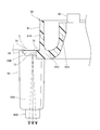
なお、本実施の形態では、ファン47が所謂軸流ファンとして構成されているが、ファン47を所謂遠心ファンとして構成してもよい。この場合には、ファン47によって生成された空気流を、保持リング60において整流するように構成してもよい。以下、ファン47を遠心ファンとしたときの構成を、図12(A)及び(B)を用いて説明する。
この図に示されるように、ファン47を遠心ファンとして構成した場合には、ファン47の羽根47Aが、保持リング60における内筒61Aの下端部の径方向内側に配置される。また、内筒61Aの下端部には、ガイド傾斜部60Aが形成されており、ガイド傾斜部60Aは、リングベース61の周方向から見た断面視で、リングベース61の径方向外側へ向かうに従い下側へ傾斜している。また、リングベース61の底部61Cには、ガイド傾斜部60Aに対してリングベース61の径方向外側において、ガイド片60Bが形成されており、ガイド片60Bは、底部61Cから下側へ延出された略円筒状に形成されている。
そして、ファン47は、遠心ファンとして構成されているため、ファン47によって、ファン47の中央側から径方向外側へ流れる空気流ACが生成される。このとき、保持リング60の上側(空気流ACの下流側)開口がファン47(羽根47A)の外径よりも小さい径で開口しているので、空気を回転軸41側に効率的に集めることができ、中央側から径方向外側へ流れる空気流ACの流れを円滑にガイドすることができる。また、ファン47の径方向外側へ流れる空気流ACは、ガイド傾斜部60Aによって整流されて、空気流ACの向きが下側に変更される。さらに、ガイド傾斜部60Aによって下側へ向かう流れに変更された空気流ACは、ガイド片60Bによってガイドされて、保持リング60から下側へ流れる。そして、保持リング60から下側へ流れた空気流ACが、エンドブラケット32の排気孔32Eから下側へ流出される。以上により、ファン47によって生成された空気流ACを、保持リング60によって整流して、エンドブラケット32の排気孔32Eから流出させることができる。したがって、照明部70L,70Rを保持し且つステータ43の下側への移動を規制する保持リング60を活用して、ファン47により生成された空気流ACを整流することができる。よって、空気流ACを整流する部材を別途設ける必要がなくなるため、部品点数の増加を一層効果的に抑制することができる。
また、ファン47を遠心ファンとして構成し、ファン47により生成された空気流ACを保持リング60によって整流する場合には、保持リング60において規制部63を省略して、ステータ43の下側への移動を、他の部材によって規制してもよい。例えば、ステータ43の下側への移動をエンドブラケット32によって規制してもよい。
また、本実施の形態では、保持リング60において、照明収容部66が、保持柱65の下端部に形成されているが、照明収容部66の上下方向の位置は任意に変更可能である。すなわち、照明部70L,70Rの上下方向の位置は任意に変更可能である。
例えば、図13に示されるように、照明部70R(照明部70L)を保持柱65の上端部において保持するように構成してもよい。この場合には、照明収容部66を保持柱65の上端部に形成すると共に、上側へ開放された凹状に形成する。また、保持柱65において、配線溝67を省略する。そして、照明部70R(照明部70L)を照明収容部66に上側から収容して、保持柱65によって保持するように構成する。また、この場合には、照明部70R(照明部70L)のLED72によって発光された光(図13の2点鎖線にて示される矢印参照)が、保持柱65における照明収容部66よりも下側部分を透過して、先端工具46の周囲を照射する。すなわち、レンズ部65Bを含む保持柱65が、LED72によって発光された光を下側へ導く導光部として機能して、当該光をファン47の下側へ導くことができる。そして、当該光をエンドブラケット32の照明孔32Fから下側へ照射して、先端工具46の周囲を照明することができる。さらに、この場合には、リード線73,74を、保持柱65の配線溝67に配策する必要がなくなる。したがって、照明部70L,70Rを保持リング60に組付けるときの組付工数を削減することができる。また、リード線73を保持リング60に取り付ける最初の位置(配線スリット68Rの位置)から下方向にかかるリード線73の配線領域を省略可能となるので、この間にかかるリード線73のばたつき、すなわち位置ずれを抑制できるというガイド溝62と同様の効果も得ることができる。
また、本実施の形態では、一対の照明部70L,70Rが、保持リング60に保持されているが、保持リング60に保持される照明部材の個数は任意に設定してもよい。すなわち、保持リング60によって保持される照明部材の個数を、1個としても3個以上としてもよい。また、本願発明を実施する形態としてルータを説明したが、本願発明は他の様々な作業機に適用可能である。特に、先端工具とモータとの間にファンが位置するような作業機に適用することができ、例えばディスクグラインダーやジグソー等の作業機にも適用可能である。
10…ルータ(作業機)、31…ハウジング、32…エンドブラケット(第2ハウジング)、32F…照明孔(係合部)、33…モータハウジング(第1ハウジング)、40…モータ、41…回転軸、42…ロータ、43…ステータ、46…先端工具、47…ファン、60…保持リング(保持部材)、61…リングベース(基部)、62…ガイド溝(溝部)、65…保持柱(延出部)、70L…照明部、70R…照明部、72…LED(光源)、73…リード線(配線)、74…リード線(配線)、80…バッテリーホルダ(分割ハウジング)、85…バッテリー(電池)、90…制御部
Claims (12)
- 回転軸と、前記回転軸に一体回転可能に構成されたロータと、前記ロータの径方向外側に配置されたステータと、を含んで構成されたモータと、
前記回転軸に設けられ、前記ロータ及び前記ステータに対して前記回転軸の軸方向一方側に配置されたファンと、
前記モータを収容するハウジングと、
前記回転軸の軸方向一端部に取付けられた先端工具と、
発光された光を前記先端工具の周囲へ向けて照射する光源を含んで構成された照明部と、
前記ファンの径方向外側に設けられ、前記ファンによって生成された空気流を整流すると共に、前記照明部を保持する保持部材と、
を備えた作業機。 - 回転軸と、前記回転軸に一体回転可能に構成されたロータと、前記ロータの径方向外側に配置されたステータと、を含んで構成されたモータと、
前記モータを収容するハウジングと、
前記回転軸に設けられ、前記ロータ及び前記ステータに対して前記回転軸の軸方向一方側に配置されたファンと、
前記回転軸の軸方向一端部に取付けられた先端工具と、
発光された光を前記先端工具の周囲へ向けて照射する光源を含んで構成された照明部と、
前記ステータに対して前記回転軸の軸方向一方側に設けられ、前記照明部を保持すると共に、前記ステータにおける前記回転軸の軸方向一方側への移動を規制する保持部材と、
を備えた作業機。 - 前記ハウジングは、
前記モータを収容する第1ハウジングと、
前記第1ハウジングに対して前記回転軸の軸方向一方側に設けられた第2ハウジングと、
を含んで構成されており、
前記保持部材が、前記回転軸の軸方向において、前記第1ハウジングと前記第2ハウジングとによって挟持されている請求項1又は請求項2に記載の作業機。 - 前記第2ハウジングには、前記保持部材と係合された係合部が形成されており、
前記回転軸の周方向における前記保持部材の回転が前記係合部によって規制されている請求項3に記載の作業機。 - 前記保持部材は、
前記ロータ及び前記ステータと前記ファンとの間に配置された基部と、
前記基部から前記回転軸の軸方向一方側へ延出された延出部と、
を含んで構成されており、
前記照明部が、前記延出部の先端部に保持されている請求項1~請求項4の何れか1項に記載の作業機。 - 前記保持部材は、
前記ロータ及び前記ステータと前記ファンとの間に配置された基部と、
前記基部から前記回転軸の軸方向一方側へ延出された延出部と、
を含んで構成されており、
前記照明部が、前記延出部の基端部に保持され、
前記延出部が前記光源によって発光された光を透過して、当該光が前記延出部の先端部から前記先端工具の周囲へ向けて照射される請求項1~請求項4の何れか1項に記載の作業機。 - 前記基部には、前記回転軸の軸方向他方側へ開放された溝部が形成されており、
前記照明部と接続された配線が、前記溝部内に配策されている請求項5又は請求項6に記載の作業機。 - 前記保持部材には、一対の前記照明部が保持されており、
一対の前記照明部を接続する配線が前記溝部内に配策されている請求項7に記載の作業機。 - 前記ハウジングに対して前記回転軸の軸方向他方側には、分割ハウジングが設けられており、前記分割ハウジングが、前記回転軸の軸方向に対して直交する方向に分割可能に構成されている請求項1~請求項8の何れか1項に記載の作業機。
- 前記分割ハウジングには、前記照明部の点灯及び消灯を制御する制御部が設けられている請求項9に記載の作業機。
- 前記分割ハウジングには、前記照明部に電力を供給する電池が着脱可能に設けられている請求項9又は請求項10に記載の作業機。
- 回転軸と、前記回転軸に一体回転可能に構成されたロータと、前記ロータの径方向外側に配置されたステータと、を含んで構成されたモータと、
前記回転軸に設けられ、前記ロータ及び前記ステータに対して前記回転軸の軸方向一方側に配置されたファンと、
前記モータを収容するハウジングと、
前記回転軸の軸方向一端部に取付けられた先端工具と、
発光された光を前記先端工具の周囲へ向けて照射する光源を含んで構成された照明部と、
前記照明部を保持する保持部材と、
を備え、
前記保持部材は、
前記ロータ及び前記ステータと前記ファンとの間に配置された基部と、
前記基部から前記回転軸の軸方向一方側へ延出され、前記照明部を保持すると共に、前記光源によって発光された光を透過し且つ先端部から当該光を前記先端工具の周囲へ向けて照射する延出部と、
を含んで構成されており、
前記延出部の先端部が、前記ファンよりも前記回転軸の軸方向一方側に配置されている作業機。
Priority Applications (4)
| Application Number | Priority Date | Filing Date | Title |
|---|---|---|---|
| CN202080095070.3A CN115023326B (zh) | 2020-01-31 | 2020-12-25 | 作业机 |
| JP2021574557A JP7327527B2 (ja) | 2020-01-31 | 2020-12-25 | 作業機 |
| US17/796,259 US20230076288A1 (en) | 2020-01-31 | 2020-12-25 | Work machine |
| DE112020006654.1T DE112020006654T5 (de) | 2020-01-31 | 2020-12-25 | Arbeitsmaschine |
Applications Claiming Priority (4)
| Application Number | Priority Date | Filing Date | Title |
|---|---|---|---|
| JP2020014326 | 2020-01-31 | ||
| JP2020-014326 | 2020-01-31 | ||
| JP2020164779 | 2020-09-30 | ||
| JP2020-164779 | 2020-09-30 |
Publications (1)
| Publication Number | Publication Date |
|---|---|
| WO2021153134A1 true WO2021153134A1 (ja) | 2021-08-05 |
Family
ID=77078987
Family Applications (1)
| Application Number | Title | Priority Date | Filing Date |
|---|---|---|---|
| PCT/JP2020/048842 WO2021153134A1 (ja) | 2020-01-31 | 2020-12-25 | 作業機 |
Country Status (5)
| Country | Link |
|---|---|
| US (1) | US20230076288A1 (ja) |
| JP (1) | JP7327527B2 (ja) |
| CN (1) | CN115023326B (ja) |
| DE (1) | DE112020006654T5 (ja) |
| WO (1) | WO2021153134A1 (ja) |
Families Citing this family (1)
| Publication number | Priority date | Publication date | Assignee | Title |
|---|---|---|---|---|
| CN114641383A (zh) * | 2019-10-31 | 2022-06-17 | 工机控股株式会社 | 刳刨机 |
Citations (4)
| Publication number | Priority date | Publication date | Assignee | Title |
|---|---|---|---|---|
| US6443675B1 (en) * | 2000-02-17 | 2002-09-03 | Roto Zip Tool Corporation | Hand-held power tool |
| JP2006326933A (ja) * | 2005-05-24 | 2006-12-07 | Hitachi Koki Co Ltd | ルータ |
| JP2017526539A (ja) * | 2014-06-10 | 2017-09-14 | ローベルト ボッシュ ゲゼルシャフト ミット ベシュレンクテル ハフツング | 定義された設計サイズを有する電子整流式の電動モータと、少なくとも1つの電圧階級の再充電可能なバッテリとを少なくとも含むシステム |
| JP2019193971A (ja) * | 2018-04-27 | 2019-11-07 | 工機ホールディングス株式会社 | 電動工具 |
Family Cites Families (14)
| Publication number | Priority date | Publication date | Assignee | Title |
|---|---|---|---|---|
| US4051880A (en) * | 1976-10-29 | 1977-10-04 | The Singer Company | Dustless routers |
| US5525842A (en) * | 1994-12-02 | 1996-06-11 | Volt-Aire Corporation | Air tool with integrated generator and light ring assembly |
| US6558090B2 (en) * | 2001-06-15 | 2003-05-06 | Porter-Cable/Delta | Cordless router |
| US6726414B2 (en) * | 2002-09-17 | 2004-04-27 | One World Technologies, Limited | Depth adjustment for a fixed base router |
| DE102010002182A1 (de) * | 2010-02-22 | 2011-08-25 | Robert Bosch GmbH, 70469 | Werkzeugmaschine mit elektrischem Generator zur passiven Stromerzeugung |
| US9028088B2 (en) * | 2010-09-30 | 2015-05-12 | Black & Decker Inc. | Lighted power tool |
| DE102011075663A1 (de) * | 2011-05-11 | 2012-11-15 | Robert Bosch Gmbh | Handwerkzeugmaschine mit einer Arbeitsfeldbeleuchtung |
| JP5757172B2 (ja) * | 2011-06-16 | 2015-07-29 | 日立工機株式会社 | 電動工具 |
| JP5937479B2 (ja) * | 2012-10-02 | 2016-06-22 | 株式会社マキタ | 電動工具 |
| CN204470650U (zh) * | 2014-12-31 | 2015-07-15 | 西安发威电子科技有限公司 | 一种手电钻 |
| US10836019B2 (en) * | 2015-01-30 | 2020-11-17 | Koki Holdings Co., Ltd. | Work machine |
| CN105162306B (zh) * | 2015-08-21 | 2017-09-22 | 郑振宇 | 一种安全特低电压产生装置及电动工具 |
| CN208468213U (zh) * | 2018-06-08 | 2019-02-05 | 广东新比克斯实业股份有限公司 | 一种冲击充电钻 |
| CN214213685U (zh) * | 2019-12-30 | 2021-09-17 | 朝程工业股份有限公司 | 电动工具 |
-
2020
- 2020-12-25 DE DE112020006654.1T patent/DE112020006654T5/de active Pending
- 2020-12-25 US US17/796,259 patent/US20230076288A1/en active Pending
- 2020-12-25 WO PCT/JP2020/048842 patent/WO2021153134A1/ja active Application Filing
- 2020-12-25 JP JP2021574557A patent/JP7327527B2/ja active Active
- 2020-12-25 CN CN202080095070.3A patent/CN115023326B/zh active Active
Patent Citations (4)
| Publication number | Priority date | Publication date | Assignee | Title |
|---|---|---|---|---|
| US6443675B1 (en) * | 2000-02-17 | 2002-09-03 | Roto Zip Tool Corporation | Hand-held power tool |
| JP2006326933A (ja) * | 2005-05-24 | 2006-12-07 | Hitachi Koki Co Ltd | ルータ |
| JP2017526539A (ja) * | 2014-06-10 | 2017-09-14 | ローベルト ボッシュ ゲゼルシャフト ミット ベシュレンクテル ハフツング | 定義された設計サイズを有する電子整流式の電動モータと、少なくとも1つの電圧階級の再充電可能なバッテリとを少なくとも含むシステム |
| JP2019193971A (ja) * | 2018-04-27 | 2019-11-07 | 工機ホールディングス株式会社 | 電動工具 |
Also Published As
| Publication number | Publication date |
|---|---|
| JP7327527B2 (ja) | 2023-08-16 |
| US20230076288A1 (en) | 2023-03-09 |
| JPWO2021153134A1 (ja) | 2021-08-05 |
| DE112020006654T5 (de) | 2022-11-24 |
| CN115023326B (zh) | 2024-03-29 |
| CN115023326A (zh) | 2022-09-06 |
Similar Documents
| Publication | Publication Date | Title |
|---|---|---|
| US6918331B2 (en) | Lighted cutting tools | |
| US20080106159A1 (en) | Portable power working machine | |
| JP3765425B2 (ja) | 携帯用電動切断機 | |
| WO2021153134A1 (ja) | 作業機 | |
| US20220203512A1 (en) | Power tool | |
| US11999045B2 (en) | Work tool | |
| US20160248295A1 (en) | Machining device and electric motor for the same | |
| JP2011131367A (ja) | 携帯用切断機 | |
| US20050278959A1 (en) | Circular saws with power indication lamps | |
| JP2013059820A (ja) | 電動工具 | |
| JP4789617B2 (ja) | 電動工具 | |
| US20110179924A1 (en) | Bench Cutting Machine | |
| CN110014190B (zh) | 便携式切割机 | |
| WO2022044771A1 (ja) | 作業機 | |
| JP6639883B2 (ja) | 加工機及び電動モータ | |
| WO2023234186A1 (ja) | 作業機 | |
| WO2022070765A1 (ja) | 作業機 | |
| JP2024095429A (ja) | 作業機 | |
| JP2024095428A (ja) | 作業機 | |
| JP4936225B2 (ja) | 携帯用切断機 | |
| WO2024117162A1 (ja) | 作業機 | |
| JP2022186175A (ja) | 作業機 | |
| JP2024110582A (ja) | 動力工具 | |
| JP2024047269A (ja) | 電動作業機及びねじ締め工具 | |
| US20230179048A1 (en) | Electric work machine |
Legal Events
| Date | Code | Title | Description |
|---|---|---|---|
| 121 | Ep: the epo has been informed by wipo that ep was designated in this application |
Ref document number: 20916757 Country of ref document: EP Kind code of ref document: A1 |
|
| ENP | Entry into the national phase |
Ref document number: 2021574557 Country of ref document: JP Kind code of ref document: A |
|
| 122 | Ep: pct application non-entry in european phase |
Ref document number: 20916757 Country of ref document: EP Kind code of ref document: A1 |