WO2021152778A1 - リチウムイオン二次電池用負極材及びその製造方法、リチウムイオン二次電池用負極、並びにリチウムイオン二次電池 - Google Patents
リチウムイオン二次電池用負極材及びその製造方法、リチウムイオン二次電池用負極、並びにリチウムイオン二次電池 Download PDFInfo
- Publication number
- WO2021152778A1 WO2021152778A1 PCT/JP2020/003463 JP2020003463W WO2021152778A1 WO 2021152778 A1 WO2021152778 A1 WO 2021152778A1 JP 2020003463 W JP2020003463 W JP 2020003463W WO 2021152778 A1 WO2021152778 A1 WO 2021152778A1
- Authority
- WO
- WIPO (PCT)
- Prior art keywords
- negative electrode
- particles
- ion secondary
- electrode material
- lithium ion
- Prior art date
- Legal status (The legal status is an assumption and is not a legal conclusion. Google has not performed a legal analysis and makes no representation as to the accuracy of the status listed.)
- Ceased
Links
Images




Classifications
-
- H—ELECTRICITY
- H01—ELECTRIC ELEMENTS
- H01M—PROCESSES OR MEANS, e.g. BATTERIES, FOR THE DIRECT CONVERSION OF CHEMICAL ENERGY INTO ELECTRICAL ENERGY
- H01M4/00—Electrodes
- H01M4/02—Electrodes composed of, or comprising, active material
- H01M4/36—Selection of substances as active materials, active masses, active liquids
- H01M4/362—Composites
-
- H—ELECTRICITY
- H01—ELECTRIC ELEMENTS
- H01M—PROCESSES OR MEANS, e.g. BATTERIES, FOR THE DIRECT CONVERSION OF CHEMICAL ENERGY INTO ELECTRICAL ENERGY
- H01M4/00—Electrodes
- H01M4/02—Electrodes composed of, or comprising, active material
- H01M4/36—Selection of substances as active materials, active masses, active liquids
- H01M4/58—Selection of substances as active materials, active masses, active liquids of inorganic compounds other than oxides or hydroxides, e.g. sulfides, selenides, tellurides, halogenides or LiCoFy; of polyanionic structures, e.g. phosphates, silicates or borates
- H01M4/583—Carbonaceous material, e.g. graphite-intercalation compounds or CFx
- H01M4/587—Carbonaceous material, e.g. graphite-intercalation compounds or CFx for inserting or intercalating light metals
-
- H—ELECTRICITY
- H01—ELECTRIC ELEMENTS
- H01M—PROCESSES OR MEANS, e.g. BATTERIES, FOR THE DIRECT CONVERSION OF CHEMICAL ENERGY INTO ELECTRICAL ENERGY
- H01M4/00—Electrodes
- H01M4/02—Electrodes composed of, or comprising, active material
- H01M4/36—Selection of substances as active materials, active masses, active liquids
- H01M4/58—Selection of substances as active materials, active masses, active liquids of inorganic compounds other than oxides or hydroxides, e.g. sulfides, selenides, tellurides, halogenides or LiCoFy; of polyanionic structures, e.g. phosphates, silicates or borates
- H01M4/583—Carbonaceous material, e.g. graphite-intercalation compounds or CFx
-
- C—CHEMISTRY; METALLURGY
- C01—INORGANIC CHEMISTRY
- C01B—NON-METALLIC ELEMENTS; COMPOUNDS THEREOF; METALLOIDS OR COMPOUNDS THEREOF NOT COVERED BY SUBCLASS C01C
- C01B32/00—Carbon; Compounds thereof
- C01B32/20—Graphite
- C01B32/205—Preparation
-
- H—ELECTRICITY
- H01—ELECTRIC ELEMENTS
- H01M—PROCESSES OR MEANS, e.g. BATTERIES, FOR THE DIRECT CONVERSION OF CHEMICAL ENERGY INTO ELECTRICAL ENERGY
- H01M10/00—Secondary cells; Manufacture thereof
- H01M10/05—Accumulators with non-aqueous electrolyte
- H01M10/052—Li-accumulators
- H01M10/0525—Rocking-chair batteries, i.e. batteries with lithium insertion or intercalation in both electrodes; Lithium-ion batteries
-
- H—ELECTRICITY
- H01—ELECTRIC ELEMENTS
- H01M—PROCESSES OR MEANS, e.g. BATTERIES, FOR THE DIRECT CONVERSION OF CHEMICAL ENERGY INTO ELECTRICAL ENERGY
- H01M4/00—Electrodes
- H01M4/02—Electrodes composed of, or comprising, active material
- H01M4/04—Processes of manufacture in general
- H01M4/0402—Methods of deposition of the material
- H01M4/0404—Methods of deposition of the material by coating on electrode collectors
-
- H—ELECTRICITY
- H01—ELECTRIC ELEMENTS
- H01M—PROCESSES OR MEANS, e.g. BATTERIES, FOR THE DIRECT CONVERSION OF CHEMICAL ENERGY INTO ELECTRICAL ENERGY
- H01M4/00—Electrodes
- H01M4/02—Electrodes composed of, or comprising, active material
- H01M4/04—Processes of manufacture in general
- H01M4/0471—Processes of manufacture in general involving thermal treatment, e.g. firing, sintering, backing particulate active material, thermal decomposition, pyrolysis
-
- H—ELECTRICITY
- H01—ELECTRIC ELEMENTS
- H01M—PROCESSES OR MEANS, e.g. BATTERIES, FOR THE DIRECT CONVERSION OF CHEMICAL ENERGY INTO ELECTRICAL ENERGY
- H01M4/00—Electrodes
- H01M4/02—Electrodes composed of, or comprising, active material
- H01M4/13—Electrodes for accumulators with non-aqueous electrolyte, e.g. for lithium-accumulators; Processes of manufacture thereof
- H01M4/133—Electrodes based on carbonaceous material, e.g. graphite-intercalation compounds or CFx
-
- H—ELECTRICITY
- H01—ELECTRIC ELEMENTS
- H01M—PROCESSES OR MEANS, e.g. BATTERIES, FOR THE DIRECT CONVERSION OF CHEMICAL ENERGY INTO ELECTRICAL ENERGY
- H01M4/00—Electrodes
- H01M4/02—Electrodes composed of, or comprising, active material
- H01M4/36—Selection of substances as active materials, active masses, active liquids
- H01M4/362—Composites
- H01M4/366—Composites as layered products
-
- C—CHEMISTRY; METALLURGY
- C01—INORGANIC CHEMISTRY
- C01P—INDEXING SCHEME RELATING TO STRUCTURAL AND PHYSICAL ASPECTS OF SOLID INORGANIC COMPOUNDS
- C01P2002/00—Crystal-structural characteristics
- C01P2002/70—Crystal-structural characteristics defined by measured X-ray, neutron or electron diffraction data
-
- C—CHEMISTRY; METALLURGY
- C01—INORGANIC CHEMISTRY
- C01P—INDEXING SCHEME RELATING TO STRUCTURAL AND PHYSICAL ASPECTS OF SOLID INORGANIC COMPOUNDS
- C01P2002/00—Crystal-structural characteristics
- C01P2002/80—Crystal-structural characteristics defined by measured data other than those specified in group C01P2002/70
- C01P2002/82—Crystal-structural characteristics defined by measured data other than those specified in group C01P2002/70 by IR- or Raman-data
-
- C—CHEMISTRY; METALLURGY
- C01—INORGANIC CHEMISTRY
- C01P—INDEXING SCHEME RELATING TO STRUCTURAL AND PHYSICAL ASPECTS OF SOLID INORGANIC COMPOUNDS
- C01P2004/00—Particle morphology
- C01P2004/20—Particle morphology extending in two dimensions, e.g. plate-like
- C01P2004/24—Nanoplates, i.e. plate-like particles with a thickness from 1-100 nanometer
-
- C—CHEMISTRY; METALLURGY
- C01—INORGANIC CHEMISTRY
- C01P—INDEXING SCHEME RELATING TO STRUCTURAL AND PHYSICAL ASPECTS OF SOLID INORGANIC COMPOUNDS
- C01P2004/00—Particle morphology
- C01P2004/50—Agglomerated particles
-
- C—CHEMISTRY; METALLURGY
- C01—INORGANIC CHEMISTRY
- C01P—INDEXING SCHEME RELATING TO STRUCTURAL AND PHYSICAL ASPECTS OF SOLID INORGANIC COMPOUNDS
- C01P2004/00—Particle morphology
- C01P2004/51—Particles with a specific particle size distribution
-
- C—CHEMISTRY; METALLURGY
- C01—INORGANIC CHEMISTRY
- C01P—INDEXING SCHEME RELATING TO STRUCTURAL AND PHYSICAL ASPECTS OF SOLID INORGANIC COMPOUNDS
- C01P2006/00—Physical properties of inorganic compounds
- C01P2006/11—Powder tap density
-
- C—CHEMISTRY; METALLURGY
- C01—INORGANIC CHEMISTRY
- C01P—INDEXING SCHEME RELATING TO STRUCTURAL AND PHYSICAL ASPECTS OF SOLID INORGANIC COMPOUNDS
- C01P2006/00—Physical properties of inorganic compounds
- C01P2006/12—Surface area
-
- C—CHEMISTRY; METALLURGY
- C01—INORGANIC CHEMISTRY
- C01P—INDEXING SCHEME RELATING TO STRUCTURAL AND PHYSICAL ASPECTS OF SOLID INORGANIC COMPOUNDS
- C01P2006/00—Physical properties of inorganic compounds
- C01P2006/19—Oil-absorption capacity, e.g. DBP values
-
- H—ELECTRICITY
- H01—ELECTRIC ELEMENTS
- H01M—PROCESSES OR MEANS, e.g. BATTERIES, FOR THE DIRECT CONVERSION OF CHEMICAL ENERGY INTO ELECTRICAL ENERGY
- H01M4/00—Electrodes
- H01M4/02—Electrodes composed of, or comprising, active material
- H01M2004/021—Physical characteristics, e.g. porosity, surface area
-
- H—ELECTRICITY
- H01—ELECTRIC ELEMENTS
- H01M—PROCESSES OR MEANS, e.g. BATTERIES, FOR THE DIRECT CONVERSION OF CHEMICAL ENERGY INTO ELECTRICAL ENERGY
- H01M4/00—Electrodes
- H01M4/02—Electrodes composed of, or comprising, active material
- H01M2004/026—Electrodes composed of, or comprising, active material characterised by the polarity
- H01M2004/027—Negative electrodes
-
- Y—GENERAL TAGGING OF NEW TECHNOLOGICAL DEVELOPMENTS; GENERAL TAGGING OF CROSS-SECTIONAL TECHNOLOGIES SPANNING OVER SEVERAL SECTIONS OF THE IPC; TECHNICAL SUBJECTS COVERED BY FORMER USPC CROSS-REFERENCE ART COLLECTIONS [XRACs] AND DIGESTS
- Y02—TECHNOLOGIES OR APPLICATIONS FOR MITIGATION OR ADAPTATION AGAINST CLIMATE CHANGE
- Y02E—REDUCTION OF GREENHOUSE GAS [GHG] EMISSIONS, RELATED TO ENERGY GENERATION, TRANSMISSION OR DISTRIBUTION
- Y02E60/00—Enabling technologies; Technologies with a potential or indirect contribution to GHG emissions mitigation
- Y02E60/10—Energy storage using batteries
Definitions
- the present disclosure relates to a negative electrode material for a lithium ion secondary battery and a method for manufacturing the same, a negative electrode for a lithium ion secondary battery, and a lithium ion secondary battery.
- Lithium-ion secondary batteries have been widely used in electronic devices such as notebook personal computers (PCs), mobile phones, smartphones, and tablet PCs by taking advantage of their characteristics of small size, light weight, and high energy density.
- PCs notebook personal computers
- HEVs hybrid electric vehicles
- PHEV plug-in hybrid electric vehicles.
- lithium ion secondary batteries vehicle-mounted lithium ion secondary batteries
- the performance of the negative electrode material of the lithium ion secondary battery has a great influence on the input characteristics of the lithium ion secondary battery.
- a carbon material is widely used as a material for a negative electrode material for a lithium ion secondary battery.
- a carbon material having a high degree of crystallinity such as artificial graphite and spherical natural graphite obtained by spheroidizing scaly natural graphite has been proposed.
- artificial graphite for example, in International Publication No. 2015/147012, a composite containing a plurality of flat graphite particles assembled or bonded so that the orientation planes are non-parallel, and spherical graphite particles.
- a negative electrode material for a lithium ion secondary battery containing particles is disclosed.
- Japanese Patent Application Laid-Open No. 2005-302725 has a form in which plate-shaped particles are oriented and laminated along a surface to form a primary stable structure, and fine pores are formed on the surface of the carbon.
- a negative electrode active material for a lithium secondary battery containing powder particles is disclosed.
- the present disclosure uses a negative electrode material for a lithium ion secondary battery capable of producing a lithium ion secondary battery having excellent high temperature resistance and excellent injectability of an electrolytic solution, a method for producing the same, and the negative electrode material. It is an object of the present invention to provide a negative electrode for a lithium ion secondary battery and a lithium ion secondary battery to be produced.
- a negative electrode material for a lithium ion secondary battery which comprises composite particles having a structure in which a plurality of flat graphite particles are laminated, and has a particle size distribution D90 / D10 of the composite particles of 2.0 to 5.0.
- ⁇ 3> The negative electrode material for a lithium ion secondary battery according to ⁇ 2>, wherein the particle size distribution D90 / D10 of the composite particles is 2.0 to 5.0.
- the specific surface area determined by nitrogen adsorption measurements at 77K of the composite particles is 0.5m 2 /g ⁇ 2.8m 2 / g, according to any one of ⁇ 1> to ⁇ 3>
- ⁇ 5> The lithium ion secondary battery according to any one of ⁇ 1> to ⁇ 4>, wherein the degree of graphitization of the composite particles determined by the X-ray diffraction method is 93.0% to 98.0%. Negative electrode material for.
- the composite particle In the composite particle, the intensity of the diffraction peak (P1) on the (101) plane of the rhombohedral structure and the diffraction peak (P2) on the (101) plane of the hexagonal structure in the X-ray diffraction pattern by CuK ⁇ rays.
- the negative electrode material for a lithium ion secondary battery according to any one of ⁇ 1> to ⁇ 5>, wherein the ratio (P1 / P2) is 0.15 or less.
- the composite particle is a composite particle in which low crystalline carbon is arranged on at least a part of the surface, and the R value of the Raman spectroscopic measurement of the composite particle in which the low crystalline carbon is arranged is 0.50 or less.
- the composite particle is a composite particle in which low crystalline carbon is not arranged on the surface, and the R value of the Raman spectroscopic measurement of the composite particle in which low crystalline carbon is not arranged is 0.20 or less.
- ⁇ 9> The negative electrode material for a lithium ion secondary battery according to any one of ⁇ 1> to ⁇ 8>, wherein the oil absorption of the composite particles is 15 mL / 100 g to 45 mL / 100 g.
- a negative electrode for a lithium ion secondary battery including a negative electrode material layer containing the negative electrode material for a lithium ion secondary battery according to any one of ⁇ 1> to ⁇ 10> and a current collector.
- the lithium ion secondary battery including the negative electrode for the lithium ion secondary battery, the positive electrode, and the electrolytic solution according to ⁇ 11>.
- a step of graphitizing the secondary particles to obtain composite particles having a structure in which a plurality of flat graphite particles are laminated.
- a method for manufacturing a negative electrode material for a lithium ion secondary battery including the above. ⁇ 14> The lithium ion secondary material according to ⁇ 13>, wherein the negative electrode material for the lithium ion secondary battery is the negative electrode material for the lithium ion secondary battery according to any one of ⁇ 1> to ⁇ 10>.
- ⁇ 16> The lithium ion 2 according to any one of ⁇ 13> to ⁇ 15>, wherein the bulk density of the secondary particles to be subjected to graphitization is 0.4 g / cm 3 to 1.0 g / cm 3.
- a method for manufacturing a negative electrode material for a next battery ⁇ 17>
- Manufacturing method. ⁇ 18> The method for producing a negative electrode material for a lithium ion secondary battery according to ⁇ 17>, which comprises reducing the pressure in the atmosphere during the heating.
- a negative electrode material for a lithium ion secondary battery capable of producing a lithium ion secondary battery having excellent high temperature resistance and excellent injectability of an electrolytic solution, a method for producing the same, and production using the negative electrode material.
- the negative electrode for a lithium ion secondary battery and the lithium ion secondary battery are provided.
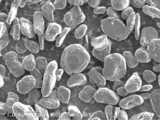
- the electron micrograph of the negative electrode material of Example 1 is shown.
- the electron micrograph of the cross section of the negative electrode material of Example 1 is shown.
- An electron micrograph of the negative electrode material of Comparative Example 1 is shown.
- An electron micrograph of a cross section of the negative electrode material of Comparative Example 1 is shown.
- An electron micrograph of the negative electrode material of Comparative Example 2 is shown.
- An electron micrograph of a cross section of the negative electrode material of Comparative Example 2 is shown.
- An electron micrograph of the negative electrode material of Comparative Example 3 is shown.
- An electron micrograph of a cross section of the negative electrode material of Comparative Example 3 is shown.
- the term "process” includes not only a process independent of other processes but also the process if the purpose of the process is achieved even if the process cannot be clearly distinguished from the other process. ..
- the numerical range indicated by using "-" in the present disclosure includes the numerical values before and after "-" as the minimum value and the maximum value, respectively.
- the upper limit value or the lower limit value described in one numerical range may be replaced with the upper limit value or the lower limit value of another numerical range described stepwise. ..
- the upper limit value or the lower limit value of the numerical range may be replaced with the value shown in the examples.
- each component may contain a plurality of applicable substances.
- the content or content of each component is the total content or content of the plurality of substances present in the composition unless otherwise specified.
- a plurality of types of particles corresponding to each component may be contained.
- the particle size of each component means a value for a mixture of the plurality of particles present in the composition unless otherwise specified.
- the term "layer” or “membrane” is used only in a part of the region in addition to the case where the layer or the membrane is formed in the entire region when the region in which the layer or the membrane is present is observed. The case where it is formed is also included.
- laminated refers to stacking layers, and two or more layers may be bonded or the two or more layers may be removable.
- the particle size distribution of the primary particles contained in the negative electrode material and the composite particles can be measured by a laser diffraction particle size distribution measuring device.
- the average particle size of the particles is the particle size (D50) when the integration from the small diameter side is 50% in the volume-based particle size distribution.
- D90 is the particle size when the integration from the small diameter side is 90% in the volume-based particle size distribution, and D10 is the particle size when the integration from the small diameter side is 10% in the volume-based particle size distribution.
- the negative electrode material for a lithium ion secondary battery according to the first embodiment of the present disclosure includes composite particles having a structure in which a plurality of flat graphite particles are laminated, and the particle size distribution D90 / D10 of the composite particles is 2.0. It is ⁇ 5.0.
- the negative electrode material according to the first embodiment of the present disclosure includes specific composite particles having a structure in which a plurality of flat graphite particles are laminated. Due to the laminated structure, when the negative electrode material is used, the interface with the electrolytic solution inside the specific composite particle can be reduced as compared with the negative electrode material described in, for example, International Publication No. 2015/147012, and electrolysis is performed even at a high temperature. It is considered that the decomposition of the liquid can be suppressed.
- the particle size distribution D90 / D10 of the specific composite particles is 2.0 to 5.0. Although the amount of pores inside the specific composite particle is relatively small, the particle size distribution D90 / D10 of the specific composite particle is 2.0 to 5.0, and the variation in particle size is relatively small. It is considered that the voids can maintain a good path of the electrolytic solution.
- the negative electrode material for a lithium ion secondary battery according to the second embodiment of the present disclosure includes composite particles having a structure in which a plurality of flat graphite particles are laminated, and the particle size distribution D90 / of the plurality of flat graphite particles.
- D10 is 2.0 to 4.4.
- the negative electrode material according to the second embodiment of the present disclosure includes specific composite particles having a structure in which a plurality of flat graphite particles are laminated. Due to the laminated structure, when the negative electrode material is used, the interface with the electrolytic solution inside the specific composite particle can be reduced as compared with the negative electrode material described in, for example, International Publication No. 2015/147012, and electrolysis is performed even at a high temperature. It is considered that the decomposition of the liquid can be suppressed.
- the laminated structure makes it difficult for the particles to be crushed even when pressure is applied when producing the negative electrode, and it is difficult to obstruct the path of the electrolytic solution. It is considered that this makes it possible to maintain good injectability of the electrolytic solution.
- the particle size distributions D90 / D10 of the plurality of flat graphite particles are 2.0 to 4.4. It is considered that the relatively uniform particle size of the plurality of flat graphite particles makes it possible to preferably form a laminated structure, reduce the amount of pores in the composite particles, and reduce the specific surface area. ..
- the negative electrode material for a lithium ion secondary battery in the first embodiment and the second embodiment of the present disclosure may be collectively referred to as “negative electrode material of the present disclosure” or “negative electrode material”.
- a composite particle having a structure in which a plurality of flat graphite particles are laminated may be referred to as a "specific composite particle”.
- the negative electrode material for a lithium ion secondary battery of the present disclosure it has also been found that the precipitation of metallic lithium on the negative electrode during charging is suppressed. The reason for this is not clear, but it is presumed that one of the reasons is that the lithium ions easily move to the positive electrode instead of staying at the negative electrode because the path of the electrolytic solution is well maintained.
- the negative electrode material of the present disclosure may or may not contain particles other than the specific composite particles. That is, the negative electrode material of the present disclosure may be substantially composed of only the specific composite particles, or may be a mixture of the specific composite particles and other particles.
- substantially composed of only specific composite particles means that a small amount of particles other than the specific composite particles (for example, 5% by mass or less, preferably 3% by mass or less) of the entire negative electrode material is mixed with the negative electrode material. Even if it is present, it means that the battery characteristics are not practically affected.
- Examples of particles other than the specific composite particles include a negative electrode material other than the specific composite particles, a conductive auxiliary agent, and the like.
- Examples of the negative electrode material other than the specific composite particles include natural graphite, artificial graphite, amorphous coated graphite, resin coated graphite, amorphous carbon, and occluded metal particles.
- Examples of the conductive auxiliary agent include carbon black, graphite, acetylene black, oxides exhibiting conductivity, nitrides exhibiting conductivity, and the like.
- the ratio of the specific composite particles to the total amount of the negative electrode material may be 50% by mass or more, or 60% by mass or more. , 70% by mass or more, 80% by mass or more, or 90% by mass or more. Further, the ratio of the specific composite particles to the total amount of the negative electrode material may be 90% by mass or less.
- the specific composite particle has a structure in which a plurality of flat graphite particles are laminated (that is, stacked).
- the flat graphite particles refer to non-spherical graphite particles having anisotropy in shape. Examples of the flat graphite particles include graphite particles having a shape such as scaly, scaly, and partially lumpy.
- the composite particle means a particle in which primary particles are aggregated or bonded to each other. That is, the specific composite particles have a structure in which a plurality of flat graphite particles are overlapped with each other with their main surfaces facing each other and aggregated or bonded. Therefore, the plurality of flat graphite particles are overlapped with each other in a substantially parallel state to form composite particles. Whether or not the flat graphite particles are laminated can be confirmed by microscopic observation.
- the state in which a plurality of flat graphite particles are aggregated or bonded means a state in which two or more flat graphite particles are aggregated or bonded.
- Bonding refers to a state in which particles are chemically bonded to each other directly or via a carbon substance.
- the “aggregate” refers to a state in which the particles are not chemically bonded to each other, but the shape as an aggregate is maintained due to the shape or the like.
- the flat graphite particles may be aggregated or bonded via a carbon substance. Examples of the carbon substance include graphite obtained by graphitizing an organic binder such as tar and pitch. Whether or not the flat graphite particles are aggregated or bonded can be confirmed by, for example, observation with a scanning electron microscope.
- the flat graphite particles and their raw materials are not particularly limited, and examples thereof include artificial graphite, scaly natural graphite, scaly natural graphite, coke, and resin. Of these, artificial graphite is preferable from the viewpoint of being hard to be deformed and having a low specific surface area.
- the ratio of natural graphite in the specific composite particles is 40% by mass or less from the viewpoint that spheroidization does not easily proceed and a laminated structure can be easily obtained. preferable.
- the average particle size of the flat graphite particles constituting the specific composite particles is, for example, preferably 5 ⁇ m to 25 ⁇ m, more preferably 8 ⁇ m to 20 ⁇ m, and 10 ⁇ m to 10 ⁇ m from the viewpoint of ease of assembly or bonding. It is more preferably 15 ⁇ m.
- the average particle size of the flat graphite particles can be determined by any of the following methods.
- the average particle size of the flat graphite particles may be determined as the median value of the particle size of any 100 flat graphite particles by observing the cross section of the specific composite particle with a scanning microscope. At this time, the particle size of each flat graphite particle is a circle-equivalent diameter which is the diameter of a circle having the same area as the projected area.
- the particle size distribution D90 / D10 of the flat graphite particles is preferably 4.4 or less, more preferably 4.0 or less, and even more preferably 3.5 or less.
- the particle size distribution D90 / D10 of the flat graphite particles may be 2.0 or more.
- the particle size distribution D90 / D10 of the flat graphite particles is preferably 2.0 to 4.4, more preferably 2.0 to 4.0, and 2.0 to 3. It is more preferably 5.
- the particle size distribution D90 / D10 of the flat graphite particles is 2.0 to 4.4.
- the particle size distribution D90 / D10 of the flat graphite particles can be obtained by any of the following methods.
- the particle size distribution D90 / D10 obtained by measuring with a laser diffraction particle size distribution measuring device (for example, SALD3100, Shimadzu Corporation) of the flat graphitizable aggregate described later as a raw material of the specific composite particles is specified. It can be regarded as the particle size distribution D90 / D10 of the flat graphite particles constituting the composite particles.
- the particle size distribution D90 / D10 of the flat graphite particles is obtained when the cross section of the specific composite particle is observed with a scanning microscope and the cumulative number of any 1000 flat graphite particles from the small diameter side is 90%. Can be obtained as the ratio of the particle size (D90) of the above to the particle size (D10) when the integrated number from the small diameter side is 10%.
- the particle size of each flat graphite particle is a circle-equivalent diameter which is the diameter of a circle having the same area as the projected area.
- the aspect ratio represented by A / B of the flat graphite particles is preferably 2 to 20, for example. It is more preferably 4 to 10.
- the aspect ratio is 2 or more, the outer surface area is further increased, so that the action of reducing the buoyancy is produced and the particles tend to aggregate.
- the aspect ratio is 20 or less
- the input / output characteristics such as the rapid charge / discharge characteristics of the lithium ion secondary battery tend to be further improved.
- the aspect ratio is 20 or less
- the flat graphite particles for each particle become thin and the number of layers increases, the gaps in the particles increase and the specific surface area increases, and as a result, it is suppressed that the storage characteristics deteriorate. There is a tendency to be able to do it.
- the aspect ratio is obtained by observing graphite particles with a microscope, arbitrarily selecting 100 graphite particles, measuring each A / B, and taking the arithmetic mean value of those measured values.
- the length A in the major axis direction and the length B in the minor axis direction are measured as follows. That is, in the projected image of the graphite particles observed using a microscope, two parallel tangents circumscribing the outer periphery of the graphite particles, the tangent line a1 and the tangent line a2 having the maximum distance are selected, and the tangent line a1 and the tangent line a2 are selected.
- the distance between the tangent line a1 and the tangent line a2 is defined as the length A in the major axis direction. Further, two parallel tangents circumscribing the outer periphery of the graphite particles, the tangent line b1 and the tangent line b2 having the minimum distance are selected, and the distance between the tangent line b1 and the tangent line b2 is set in the minor axis direction. Let the length be B.
- the specific composite particles may have low crystalline carbons arranged on at least a part of the surface.
- the specific composite particles may be those in which low crystalline carbon is not arranged on the surface. If low crystalline carbon is not arranged on the surface of the specific composite particles, it is possible to prevent the specific composite particles from cracking, peeling, etc. in the press during electrode fabrication, increasing the decomposition activity of the electrolytic solution and deteriorating the storage characteristics. There is a tendency to be able to do it. In addition, this has the advantage of increasing the degree of freedom in manufacturing conditions.
- the rapid input / output characteristics tend to be excellent even when the low crystalline carbon is not arranged on the surface. It is considered that this is because the liquid circulation (and therefore the diffusion rate of solvated lithium) has a greater influence on the rapid input / output characteristics than the surface structure of the specific composite particles.
- Low crystalline carbon means carbon having an R value of 0.2 or more in the Raman spectrum.
- the R value is determined by setting the intensity of the maximum peak appearing near 1360 cm -1 as Id and the intensity of the maximum peak appearing near 1580 cm -1 as Ig in laser Raman spectroscopic measurement with an excitation wavelength of 532 nm. It is a value given as an intensity ratio Id / Ig.
- the peak appearing near 1360 cm -1 is a peak usually identified to correspond to the amorphous structure of carbon, and means, for example, a peak observed at 1300 cm -1 to 1400 cm -1.
- the peak appearing near 1580 cm -1 generally a peak identified as corresponding to the graphite crystal structure, for example, refers to peaks observed at 1530cm -1 ⁇ 1630cm -1.
- the R value is measured using a Raman spectrum measuring device (for example, NSR-1000 type manufactured by JASCO Corporation), and the obtained spectrum is carried out under the following conditions with the following range as the baseline.
- -Laser wavelength 532 nm
- Irradiation intensity 1.5mW (measured value with laser power monitor)
- -Measurement range 830 cm -1 to 1940 cm -1
- Irradiation time 60 seconds
- Irradiation area 4 ⁇ m 2
- Baseline 1050cm -1 ⁇ 1750cm -1
- the average particle size of the specific composite particles is, for example, preferably 5 ⁇ m to 30 ⁇ m, more preferably 10 ⁇ m to 25 ⁇ m, and further preferably 12 ⁇ m to 20 ⁇ m. preferable.
- the average particle size of the specific composite particle can be measured by a laser diffraction particle size distribution measuring device (for example, SALD3100, Shimadzu Corporation).
- the average particle size is the particle size (D50) when the integration from the small diameter side is 50% in the volume-based particle size distribution.
- a sample electrode is prepared, the electrode is embedded in an epoxy resin, and then mirror-polished.
- a method of observing an electrode cross section with a scanning electron microscope for example, "VE-7800” manufactured by Keyence Co., Ltd.
- an electrode cross section using an ion milling device for example, "E-3500” manufactured by Hitachi High Technology Co., Ltd.
- Examples thereof include a method of producing the above and measuring with a scanning electron microscope (for example, "VE-7800” manufactured by Keyence Co., Ltd.).
- the average particle size in this case is the median value of 100 particle sizes arbitrarily selected from the specific composite particles.
- the particle size distribution D90 / D10 of the specific composite particles in the negative electrode material is preferably 5.0 or less, more preferably 4.0 or less, and even more preferably 3.0 or less.
- the particle size distribution D90 / D10 of the specific composite particle may be 2.0 or more. From the above viewpoint, the particle size distribution D90 / D10 of the specific composite particles is preferably 2.0 to 5.0, more preferably 2.0 to 4.0, and 2.0 to 3.0. Is even more preferable.
- the particle size distribution D90 / D10 of the specific composite particles in the negative electrode material is 2.0 to 5.0.
- the particle size distribution D90 / D10 can be measured by a laser diffraction particle size distribution measuring device (for example, SALD3100, Shimadzu Corporation).
- a sample electrode is prepared, the electrode is embedded in an epoxy resin, and then mirror polishing is performed. Then, a method of observing the electrode cross section with a scanning electron microscope (for example, "VE-7800” manufactured by Keyence Co., Ltd.) and an ion milling device (for example, "E-3500” manufactured by Hitachi High Technology Co., Ltd.) are used. Examples thereof include a method in which an electrode cross section is prepared and measured with a scanning electron microscope (for example, “VE-7800” manufactured by Keyence Co., Ltd.).
- the particle size at the point where the distribution curve with the vertical axis as the integrated% of the volume of 100 pieces and the horizontal axis as the particle size intersects the 10% horizontal axis is 10% diameter (D10) and 90% horizontal.
- D90 / D10 can be obtained by setting the particle size at the point where the axis intersects as 90% diameter (D90).
- the standard deviation of the particle size distribution of the specific composite particles in the negative electrode material is preferably 0.30 or less, more preferably 0.25 or less, and even more preferably 0.20 or less.
- the lower limit of the standard deviation of the particle size distribution is not particularly limited.
- the standard deviation of the particle size distribution is determined by a laser diffraction particle size distribution measuring device (for example, SALD3100, Shimadzu Corporation) based on a frequency distribution graph in which the horizontal axis is the logarithmic scale of the particle size and the vertical axis is the particle amount (%). Can be measured.
- Specific composite particles specific surface area determined by nitrogen adsorption measurements at 77K (N 2 specific surface area) is preferably 0.5m 2 /g ⁇ 2.8m 2 / g, 0.5m 2 / g ⁇ more preferably 2.4m is 2 / g, 0.5m 2 /g ⁇ 2.2m more preferably from 2 / g, 0.5 m 2 / g or more that 2.0m less than 2 / g Is particularly preferable.
- the specific surface area is 0.5 m 2 / g or more, the current density per unit area does not rise sharply and the load is suppressed, so that the rapid charge / discharge efficiency tends to improve.
- the specific surface area is 2.8 m 2 / g or less, the interface with the electrolytic solution does not become too large and the decomposition of the electrolytic solution is suppressed, so that better high temperature resistance tends to be obtained.
- the N 2 specific surface area can be obtained by using the BET method from the adsorption isotherm obtained from the nitrogen adsorption measurement at 77K.
- the specific surface area can be determined by the method described in Examples.
- the oil absorption of the specific composite particles is preferably 10 mL / 100 g to 60 mL / 100 g, more preferably 15 mL / 100 g to 45 mL / 100 g, and even more preferably 20 mL / 100 g to 40 mL / 100 g. It is considered that the oil absorption amount of 45 mL / 100 g or less indicates that the amount of pores existing in the particles and on the particle surface is small. As a result, it is considered that the interface with the electrolytic solution is small and the storage characteristics can be improved. In addition, since the interface is small, it is possible to reduce the amount of binder when manufacturing the negative electrode, which tends to reduce the electrical resistance and improve the battery performance.
- the number of pores is small, it is possible to reduce the amount of solvent used when drying the electrode, which is advantageous in terms of cost and environment of the production line, such as reduction of equipment and electric power related to drying.
- the oil absorption amount is 10 mL / 100 g or more, it tends to be possible to suppress an increase in the viscosity of the slurry when kneading with a binder or the like due to the small number of voids between the particles.
- the binder is preferably spread easily and tends to be easily kneaded. In addition, it becomes easy to secure voids between particles for the movement of lithium ions.
- the oil absorption amount is not dibutyl phthalate (DBP) as the reagent liquid described in JIS K6217-4: 2017 "Carbon Black for Rubber-Basic Characteristics-Part 4: How to Obtain Oil Absorption Amount", but linseed oil. It can be measured by using oil (for example, manufactured by Kanto Chemical Co., Inc.). Specifically, linseed oil is titrated on the target powder with a constant velocity burette, and the change in viscosity characteristics is measured from a torque detector. The amount of linseed oil added per unit mass of the target powder corresponding to the torque of 70% of the generated maximum torque is defined as the oil absorption amount (mL / 100 g). As the measuring device, for example, an absorption amount measuring device (trade name: S-500) of Asahi Research Institute Co., Ltd. can be used. Specifically, the oil absorption amount can be determined by the method described in Examples.
- DBP dibutyl phthalate
- Saturated tapping density of particular composite particle is not particularly limited, is preferably from 0.80g / cm 3 ⁇ 1.60g / cm 3, more to be 0.90g / cm 3 ⁇ 1.50g / cm 3 preferably, further preferably 1.00g / cm 3 ⁇ 1.40g / cm 3.
- the saturated tap density is an index of increasing the density of the negative electrode.
- the saturation tap density is 0.80 g / cm 3 or more, the compressibility when forming the negative electrode is further improved, a high electrode density is achieved, and a lithium ion secondary battery having a higher capacity tends to be obtained.
- the saturation tap density is 1.60 g / cm 3 or less, voids between particles are preferably present, the permeability of the electrolytic solution is further improved, and input / output characteristics such as rapid charge / discharge characteristics tend to be further improved. ..
- the saturation tap density of the specific composite particle can be determined by a known method. For example, after putting 100 cm 3 of sample powder into a flat-bottomed test tube with a scale of 150 cm 3 (for example, KRS-406 manufactured by Kuramochi Kagaku Kikai Seisakusho Co., Ltd.) and dropping it from a height of 5 cm with a stopper. It is obtained from the mass (g) and volume (cm 3 ) of the sample powder. The number of taps may be until the density is saturated. Specifically, the saturated tap density can be determined by the method described in Examples.
- a press pressure that is measured by the following method is preferably at 2.1kN / cm 2 or more, more preferably 2.4 kN / cm 2 or more, 2.7kN / cm 2 or more Is more preferable.
- the press pressure can be used as one of the indexes of the hardness of the specific composite particles.
- the press pressure is 2.1 kN / cm 2 or more, the hardness of the specific composite particles is relatively high, and even if pressure is applied during the production of the negative electrode, the path of the electrolytic solution is likely to be well maintained when the battery is used. There is a tendency.
- the press pressure may be 4.5 kN / cm 2 or less, 4.3 kN / cm 2 or less, or 4.0 kN / cm 2 or less.
- the press pressure is 4.5 kN / cm 2 or less, the hardness is not too high, so that the press pressure when manufacturing the negative electrode can be suppressed, and the underlying copper foil is rolled to cause dimensional deviation or warpage. There is a tendency that it can be suppressed that it is generated, or that peeling occurs at the interface between the active material and the current collector, resulting in a decrease in capacity, an increase in resistance, and the like.
- the pressing pressure is 2.1kN / cm 2 ⁇ 4.5kN / cm 2, more preferably from 2.4kN / cm 2 ⁇ 4.3kN / cm 2, 2.7kN It is more preferably / cm 2 to 4.0 kN / cm 2.
- the press pressure is measured by the following method.
- a mold having a diameter of 15 mm is filled with 3.0 g of specific composite particles, and compressed at a constant speed of 10 mm / min using an autograph (for example, manufactured by Shimadzu Corporation).
- an autograph for example, manufactured by Shimadzu Corporation.
- the press hammer of the autograph is equipped with a load cell, and the pressing pressure (kN / cm 2 ) when the predetermined density reaches 1.8 g / cm 3 is used as the press pressure.
- the press pressure can be obtained by the method described in Examples.
- the amount of springback measured by the following method is preferably 40% or more, more preferably 45% or more, and further preferably 50% or more.
- the amount of springback is an index of the elasticity of the specific composite particle, and it can be said that the larger the value, the more elastic the specific composite particle. Therefore, when the amount of springback is 40% or more, the specific composite material has appropriate elasticity, and even if pressure is applied during the production of the negative electrode, the shape is likely to return, which is preferable.
- the amount of springback is determined by compressing the specific composite particles until the density of the specific composite particles reaches 1.8 g / cm 3, and then releasing the pressure to bring the density to 1.8 g / cm 3 and the specific composite after the pressure is released. It is obtained by dividing the absolute value of the difference from the density of the particles by the density of 1.8 g / cm 3. Specifically, a mold having a diameter of 15 mm is filled with 3.0 g of specific composite particles, and an autograph (for example, manufactured by Shimadzu Corporation) is used to obtain the specific composite particles at a constant speed of 10 mm / min. Compress until the density of the specific composite particles reaches 1.8 g / cm 3 (reference density).
- the pressure is released and the absolute value of the difference between the density of 1.8 g / cm 3 and the density of the composite particles after the pressure is released is divided by the density of 1.8 g / cm 3.
- the amount of springback can be determined by the method described in the examples.
- the intensity ratio (P1) of the diffraction peak (P1) of the (101) plane of the rhombohedral structure and the diffraction peak (P2) of the (101) plane of the hexagonal structure in the X-ray diffraction pattern by CuK ⁇ rays. / P2, also referred to as rhombohedral structure peak intensity ratio) may be 0.15 or less, 0.10 or less, or 0.05 or less.
- the peak intensity ratio (P1 / P2) is preferably in a range that cannot be observed by the following method. When the peak intensity ratio (P1 / P2) is 0.15 or less, the degree of graphitization of the negative electrode material for the lithium ion secondary battery tends to be higher, and the charge / discharge capacity tends to be higher.
- the rhombohedral structure peak intensity ratio is the rhombohedral structure diffraction line (P1: diffraction angle 43.2 °) and the hexagonal structure diffraction line (P2: diffraction angle 44) in the X-ray diffraction pattern using CuK ⁇ rays. It can be calculated from the intensity ratio of .3 °).
- the diffraction angle is represented by 2 ⁇ ( ⁇ is Bragg angle)
- the diffraction line of the (101) plane of the rhombohedral structure appears at the diffraction angle 43.2 °, and the diffraction angle is 44.3 °.
- a diffraction line on the (101) plane of the hexagonal structure appears.
- the rhombic crystal structure peak intensity ratio is obtained by adjusting the degree of graphitization (for example, adjusting the heat treatment temperature), graphitizing at a predetermined bulk density in the process of producing specific composite particles, and blocking before graphitization. It can be adjusted by not performing crushing after molding and graphitization, or by performing graphitization after molding but crushing with a weak force.
- the degree of graphitization of the specific composite particles determined by the X-ray diffraction method is preferably 93.0% to 98.0% or less, more preferably 93.5% to 97.0% or less. It may be 94.0% to 96.0% or less.
- the degree of graphitization is 98.0% or less, the hardness of the specific composite particles tends to be high, and as a result, the particles have elasticity and tend to be hard to be crushed even when pressed. Therefore, the injectability of the electrolytic solution tends to be more preferably maintained.
- the degree of graphitization is 93.0% or more, the discharge capacity tends to be excellent.
- an X-ray diffraction measuring device for example, an X-ray diffraction measuring device X-RAY DIFFRACTIOMETER MultiFlex manufactured by Rigaku Co., Ltd.
- Graphitization degree [(3.44-plane spacing) / (0.086)] ⁇ 100
- the average interplanar spacing (d 002 ) determined by the X-ray diffraction method in the specific composite particle is preferably 0.33557 nm or more, more preferably 0.33566 nm or more, and preferably 0.33574 nm or more. More preferred.
- the theoretical value of the average interplanar spacing (d 002 ) of graphite crystals is 0.3354 nm, and the closer to this value, the more graphitized.
- the average interplanar spacing (d 002 ) is 0.33557 nm or more, graphitization does not proceed too much and the particles are relatively hard, so that even if pressure is applied during the production of the negative electrode, the electrolytic solution can be used. The path tends to be well maintained.
- the average surface spacing (d 002 ) is preferably 0.33600 nm or less, more preferably 0.33596 nm or less, and 0.33592 nm. The following is more preferable.
- the average surface spacing (d 002 ) is preferably 0.33557 nm to 0.33600 nm, more preferably 0.33566 nm to 0.33596 nm, and preferably 0.33574 nm to 0.33592 nm. More preferred.
- the average surface spacing (d 002 ) appears in the vicinity of the diffraction angle 2 ⁇ of 24 ° to 27 ° in the diffraction profile obtained by irradiating the sample with X-rays (CuK ⁇ rays) and measuring the diffraction lines with a goniometer. , Can be calculated using Bragg's equation based on the diffraction peak corresponding to the carbon 002 plane.
- the value of the average interplanar spacing (d 002 ) of the specific composite particles tends to decrease by increasing the temperature of the heat treatment when producing the composite particles and lengthening the holding time, for example. Therefore, the average surface spacing (d 002 ) can be controlled by adjusting the temperature and holding time of the heat treatment when producing the specific composite particles.
- the R value (hereinafter, also referred to as R value) of Raman measurement is not particularly limited.
- the R value is preferably 0.20 or less, and from the viewpoint of high durability, 0.15. It is preferably 0 or less, and more preferably 0.10 or less. Further, the R value may be 0.03 or more, 0.04 or more, or 0.05 or more. When the R value is 0.03 or more, lithium ions are likely to be inserted into the graphite crystal and the charging characteristics tend to be improved, and the generation of lithium dendrite tends to be suppressed.
- the R value is preferably 0.50 or less, and from the viewpoint of high temperature durability.
- the R value is more preferably 0.40 or less, and further preferably 0.30 or less.
- the R value may be in the range of 0.20 to 0.50, may be in the range of 0.20 to 0.40, and may be in the range of 0.20 to 0.30. May be good.
- the R value is in the range of 0.20 to 0.50, lithium ions are easily desolvated, and there are many lithium insertion ports, so that the low temperature charging characteristics tend to be improved.
- the R value of Raman measurement can be obtained by the method described above.
- the negative electrode material of the present disclosure is a mixture of specific composite particles and particles other than the specific composite particles, the average particle size, particle size distribution D90 / D10, standard deviation of particle size distribution, specific surface area, etc. for the above-mentioned specific composite particles, Details of oil absorption, saturated tap density, press pressure, springback amount, rhombic crystal structure peak intensity ratio, degree of graphitization, average interplanar spacing (d002), and R value of Raman measurement are as characteristics of the entire negative electrode material. Can be applied in the same way.
- the method of manufacturing the negative electrode material of the present disclosure is (A) A step of mixing a plurality of flat graphitizable aggregates with a binder to obtain a mixture, and (B) A step of processing the mixture to produce secondary particles having a structure in which the plurality of flat graphitizable aggregates are laminated. (C) A step of graphitizing the secondary particles to obtain composite particles (specific composite particles) having a structure in which a plurality of flat graphite particles are laminated. Is included in this order.
- the negative electrode material for a lithium ion secondary battery of the present disclosure described above may be manufactured by the method for producing a negative electrode material of the present disclosure. As the details of the negative electrode material produced by the method for producing the negative electrode material of the present disclosure, the above-mentioned matters described for the negative electrode material for a lithium ion secondary battery can be applied.
- the method for producing the negative electrode material is selected from the group consisting of fine particles and coarse particles by classifying a plurality of flat graphitizable aggregates before the step of obtaining a mixture in the step (A). It may include the step of removing at least one of them.
- the method for producing a negative electrode material removes at least one selected from the group consisting of fine particles and coarse particles by classifying the composite particles after the step of obtaining the composite particles in the step (C).
- the process may be included. It is considered that the classification of the specific composite particles suppresses the variation in the particle size of the specific composite particles and can maintain the path of the electrolytic solution better.
- the method for producing the negative electrode material is (A) If necessary, a step of classifying a plurality of flat graphitizable aggregates and removing at least one selected from the group consisting of fine particles and coarse particles. (B) A step of mixing a plurality of flat graphitizable aggregates with a binder to obtain a mixture, and (C) A step of processing the mixture to produce secondary particles having a structure in which the plurality of flat graphitizable aggregates are laminated. (D) A step of graphitizing the secondary particles to obtain composite particles (specific composite particles) having a structure in which a plurality of flat graphite particles are laminated. (E) If necessary, a step of classifying the composite particles and removing at least one selected from the group consisting of fine particles and coarse particles. Is included in this order.
- fine particles refer to particles having a smaller particle size than the particles recovered by classification
- coarse particles refer to particles having a larger particle size than the particles recovered by classification
- the plurality of flat graphitizable aggregates may be classified prior to compounding to remove at least one selected from the group consisting of fine and coarse particles.
- removing at least one of the aggregates selected from the group consisting of fine particles and coarse particles a dense laminated structure is formed in the composite particles, and the specific surface area tends to be kept low.
- the particle size distribution D90 / D10 of the plurality of flat graphitizable aggregates is in the above range, for example 2.0 to 4.4, preferably 2.0 to 4.0, more preferably 2.0. It may be adjusted to be ⁇ 3.5.
- the aggregate that can be graphitized is not particularly limited as long as it is flat particles, and examples thereof include petroleum-based or coal-based coke such as fluid coke, needle coke, and mosaic coke.
- petroleum-based or coal-based coke such as fluid coke, needle coke, and mosaic coke.
- needle coke since needle coke has high crystallinity, it tends to be flattened and laminated particles can be easily obtained. Further, since needle coke has high crystallinity, the grains are large, and it is easy to adjust the particle size by pulverization and classification. If it is desired to obtain graphite having high charging characteristics and lower crystallinity, a semi-needle or mosaic coke that is closer to a mosaic system may be used. In this case, since fine powder and coarse powder tend to be generated, it is preferable to sufficiently remove the fine powder and coarse powder by classification adjustment.
- the classification for example, it is preferable to remove fine particles having a particle size of 1 ⁇ m or less, more preferably to remove fine particles having a particle size of 2 ⁇ m or less, and further preferably to remove fine particles having a particle size of 3 ⁇ m or less.
- the classification for example, it is preferable to remove coarse particles having a particle size of 60 ⁇ m or more, more preferably to remove coarse particles having a particle size of 50 ⁇ m or more, and further preferably to remove coarse particles having a particle size of 40 ⁇ m or more.
- the removed coarse particles may be crushed and used again as a raw material.
- the classification method is not particularly limited, and examples thereof include a classification using a sieve, a classification using an airflow centrifuge, and a precision airflow classifier using the Coanda effect.
- a binder that can be graphitized is used.
- the binder include coal-based, petroleum-based, artificial pitch and tar, thermoplastic resins, thermosetting resins, and the like.
- a graphitization catalyst, a fluidity imparting agent and the like may be added.
- the graphitizing catalyst include substances having a graphitizing catalytic action such as silicon, iron, nickel, titanium, boron, vanadium, and aluminum, carbides, oxides, nitrides, and mica clay minerals of these substances.
- the content of the graphitizing catalyst is not limited as long as the desired product can be obtained. From the viewpoint of not advancing graphitization too much, it is preferable not to blend the graphitization catalyst or to reduce the blending amount.
- the graphitizing catalyst is silicon carbide (SiC)
- the content of silicon carbide is preferably 5% by mass or less, preferably 3% by mass or less, based on the mass of the graphitizable aggregate. Is more preferable.
- the mixing method is not particularly limited. From the viewpoint of reducing the amount of pores in the secondary particles, a method of mixing so as not to give a shearing force as much as possible, for example, a method of mixing using a kiln type mixer, a huddle stirrer, or the like is preferable. It is preferable not to use a kneader or the like that involves kneading, which is called a kneading machine.
- the processing method of the mixture is not particularly limited.
- the mixture may be processed by heating to volatilize the volatile components of the binder.
- the heating temperature is preferably 400 ° C. or lower.
- the heating temperature is 400 ° C. or lower, it is difficult to make fine holes due to oxidative combustion, and it becomes easy to obtain particles having a small specific surface area.
- by heating the mixture while flowing it with a stirrer or the like it becomes easier to preferably granulate.
- the atmosphere When heating the mixture, the atmosphere may be depressurized. By reducing the pressure in the atmosphere, the binder tends to impregnate the graphitizable aggregate, fills the gaps in the particles, and tends to obtain laminated particles with few internal pores.
- the mixture of the graphitizable aggregate and the binder is stirred and mixed over a period of time until the volatile components are removed while stirring at the softening point of the binder or higher, preferably in a temperature range where the volatile components are volatilized.
- the generation of bubbles is reduced when the crystal is sintered, and the particles have few pores in the particles and on the surface of the particles, and are hard and have a low specific surface area.
- the structure tends to be excellent in high temperature resistance.
- an inert gas such as nitrogen
- the temperature inside the mixer is 400 ° C. or lower, fine holes due to oxidative combustion are less likely to be formed, and particles having a small specific surface area can be easily obtained, which is preferable.
- a pitch is used as a binder, oxygen in the atmosphere can be taken into the pitch to make it infusible. As a result, crystal development becomes good during graphitization, and a denser and higher crystal body can be obtained.
- the obtained secondary particles are graphitized.
- the graphitizable component in the secondary particles is graphitized.
- Graphitization is preferably carried out in an atmosphere in which the mixture is difficult to oxidize, and examples thereof include a method of heating in a nitrogen atmosphere or in an argon gas.
- the temperature at the time of graphitization is not particularly limited as long as it is a temperature at which the graphitizable component can be graphitized. For example, it may be 2000 ° C. or higher, 2500 ° C. or higher, 2800 ° C.
- the upper limit of the temperature is not particularly limited as long as the graphite does not sublimate, and may be, for example, 3200 ° C. or lower.
- the temperature is 2000 ° C. or higher, crystal changes occur.
- the temperature is 2500 ° C. or higher, the graphite crystals develop well, and when the temperature is 2800 ° C. or higher, the graphite crystals develop into high-capacity graphite crystals that can occlude more lithium ions, and the graphite catalyst remains after firing.
- the amount of graphite is small and the increase in ash content tends to be suppressed. In either case, the charge / discharge capacity and the cycle characteristics of the battery tend to be good.
- the temperature at the time of graphitization is 3200 ° C. or lower, sublimation of a part of graphite can be suppressed.
- the degree of graphitization may be adjusted to 98.0% or less, preferably 97.0% or less, and more preferably 96.0% or less.
- the method for producing a negative electrode material of the present disclosure may include a step of molding secondary particles before graphitization and a step of crushing the molded product after graphitization.
- the molding method is not particularly limited, and for example, secondary particles may be placed in a container such as a mold and pressurized.
- the method for producing the negative electrode material of the present disclosure does not include a step of forming secondary particles before graphitization.
- the method for producing a negative electrode material of the present disclosure does not include a step of molding secondary particles before graphitization, and therefore does not include a step of pulverizing the molded product.
- the increase of rhombohedral crystals in the process of molding and pulverization such as blocking can be suppressed, and the high temperature resistance can be more preferably improved.
- the bulk density of the secondary particles when subjected to graphitization is preferably 0.4 g / cm 3 to 1.0 g / cm 3 , and is preferably 0.6 g / cm 3 to 1. more preferably .0g / cm 3, further preferably 0.8g / cm 3 ⁇ 1.0g / cm 3.
- the bulk density of the secondary particles before graphitization is 0.4 g / cm 3 or more, there is a tendency that high-density composite particles can be obtained even after graphitization because the voids in the particles are relatively small.
- the crushing can be performed with a weak force when forming and crushing such as blocking, and the rhombohedral crystals can be crushed. There is a tendency that the increase can be suppressed.
- the bulk density of particles can be determined by a weight measurement method. That is, the bulk density of the particles can be obtained by dividing the mass of the particles in the air by the bulk capacity.
- the mass of the particles is the mass excluding the graphitization catalyst (for example, when the secondary particles are mixed particles of the aggregate, the binder, and the graphitization catalyst, the total mass excluding the volatile components of the aggregate and the binder).
- the obtained composite particles may be classified to remove at least one selected from the group consisting of fine particles and coarse particles.
- the particle size of the composite particles can be made uniform and the path of the electrolytic solution can be more preferably maintained.
- the particle size distribution D90 / D10 of the composite particles is adjusted to be in the above range, for example, 2.0 to 5.0, preferably 2.0 to 4.0, and more preferably 2.0 to 3.0. You may.
- the classification method is not particularly limited, and examples thereof include a classification using a sieve, a classification using an airflow centrifuge, and a precision airflow classifier using the Coanda effect.
- removing fine particles in this step for example, it is preferable to remove fine particles having a particle size of 1 ⁇ m or less, more preferably to remove fine particles having a particle size of 2 ⁇ m or less, and further preferably to remove fine particles having a particle size of 3 ⁇ m or less. ..
- removing coarse particles in this step for example, it is preferable to remove coarse particles having a particle size of 60 ⁇ m or more, more preferably to remove coarse particles having a particle size of 50 ⁇ m or more, and to remove coarse particles having a particle size of 40 ⁇ m or more. Is even more preferable.
- the method for producing the negative electrode material of the present disclosure may include steps other than the above-mentioned steps.
- the method for producing a negative electrode material may include a step of adhering an organic compound to the surface of secondary particles and heat-treating them after graphitization. By adhering the organic compound to the surface of the secondary particles and performing the heat treatment, the organic compound adhering to the surface is changed to low crystalline carbon. As a result, low crystalline carbon can be arranged on at least a part of the surface of the composite particle.
- the method of adhering the organic compound to the surface of the secondary particles is not particularly limited.
- a wet method in which secondary particles are dispersed and mixed in a mixed solution in which an organic compound is dissolved or dispersed in a solvent, and then the solvent is removed and adhered; the secondary particles and a solid organic compound are mixed.
- Examples thereof include a dry method in which mechanical energy is applied to the obtained mixture to attach it.
- the organic compound is not particularly limited as long as it changes to low crystalline carbon by heat treatment (carbon precursor).
- carbon precursor for example, petroleum-based pitch, naphthalene, anthracene, phenanthroline, coal tar, phenol resin, polyvinyl alcohol and the like can be mentioned.
- One type of organic compound may be used alone, or two or more types may be used in combination.
- the heat treatment temperature at the time of heat-treating the secondary particles having the organic compound attached to the surface is not particularly limited as long as the temperature at which the organic compound attached to the surface of the secondary particles changes to low crystalline carbon, for example, 400.
- the temperature is preferably -1500 ° C.
- the heat treatment is preferably performed in an inert gas atmosphere such as a nitrogen atmosphere.
- the specific composite particles contained in the negative electrode material of the present disclosure do not have to have low crystalline carbon arranged on the surface thereof. Therefore, the method for producing the negative electrode material of the present disclosure is graphitization. It is not necessary to include a step of attaching an organic compound to the surface of the secondary particles and heat-treating the particles later.
- the negative electrode for a lithium ion secondary battery of the present disclosure includes a negative electrode material layer containing the negative electrode material for a lithium ion secondary battery of the present disclosure, and a current collector.
- the negative electrode for a lithium ion secondary battery may include, if necessary, other components in addition to the negative electrode material layer and the current collector containing the negative electrode material for the lithium ion secondary battery of the present disclosure.
- a negative electrode material for a lithium ion secondary battery and a binder are kneaded together with a solvent to prepare a slurry negative electrode material composition for the lithium ion secondary battery, and the current is collected. It is produced by applying it on the body to form a negative electrode material layer, or the negative electrode material composition for a lithium ion secondary battery is formed into a sheet shape, a pellet shape, or the like, and this is integrated with the current collector. It can be made by. Kneading can be performed using a disperser such as a disperser stirrer or a planetary kneader.
- the binder used for preparing the negative electrode material composition for the lithium ion secondary battery is not particularly limited.
- the binder include ethylenically unsaturated carboxylic acid esters such as styrene-butadiene copolymer (SBR), methyl acrylate, methyl methacrylate, ethyl acrylate, ethyl methacrylate, butyl acrylate, butyl methacrylate, hydroxyethyl acrylate, and hydroxyethyl methacrylate.
- SBR styrene-butadiene copolymer
- the negative electrode material composition for a lithium ion secondary battery contains a binder
- the content of the binder is not particularly limited.
- the amount may be 0.5 parts by mass to 20 parts by mass with respect to 100 parts by mass in total of the negative electrode material for the lithium ion secondary battery and the binder.
- the negative electrode material composition for a lithium ion secondary battery may contain a thickener.
- a thickener carboxymethyl cellulose, methyl cellulose, hydroxymethyl cellulose, ethyl cellulose, polyvinyl alcohol, polyacrylic acid or a salt thereof, oxidized starch, phosphorylated starch, casein and the like can be used.
- the content of the thickener is not particularly limited. For example, it may be 0.1 parts by mass to 5 parts by mass with respect to 100 parts by mass of the negative electrode material for a lithium ion secondary battery.
- the negative electrode material composition for a lithium ion secondary battery may contain a conductive auxiliary material.
- the conductive auxiliary material include carbon materials such as carbon black, graphite and acetylene black, oxides exhibiting conductivity, and inorganic compounds such as nitrides exhibiting conductivity.
- the content of the conductive auxiliary material is not particularly limited. For example, it may be 0.5 parts by mass to 15 parts by mass with respect to 100 parts by mass of the negative electrode material for a lithium ion secondary battery.
- the material of the current collector is not particularly limited and can be selected from aluminum, copper, nickel, titanium, stainless steel, etc.
- the state of the current collector is not particularly limited and can be selected from foil, perforated foil, mesh and the like. Further, a porous material such as porous metal (foamed metal), carbon paper, or the like can also be used as a current collector.
- the method is not particularly limited, and the metal mask printing method, electrostatic coating method, dip coating method, and spray coating method are not particularly limited.
- a known method such as a method, a roll coating method, a doctor blade method, a comma coating method, a gravure coating method, or a screen printing method can be adopted.
- the solvent contained in the negative electrode material composition for a lithium ion secondary battery is removed by drying. Drying can be performed using, for example, a hot air dryer, an infrared dryer, or a combination of these devices. If necessary, the negative electrode material layer may be rolled. The rolling process can be performed by a method such as a flat plate press or a calendar roll.
- the method of integration is not particularly limited. For example, it can be performed by a roll, a flat plate press, or a combination of these means.
- the pressure at which the negative electrode material composition for a lithium ion secondary battery is integrated with the current collector is preferably, for example, about 1 MPa to 200 MPa.
- the negative electrode density of the negative electrode material layer is not particularly limited. For example, it is preferably 1.1 g / cm 3 to 1.8 g / cm 3 , more preferably 1.1 g / cm 3 to 1.7 g / cm 3 , and 1.1 g / cm 3 to 1. It is more preferably 6 g / cm 3.
- the negative electrode density is preferably 1.1 g / cm 3 or more, the increase in electrical resistance tends to be suppressed and the capacity tends to increase, and by setting it to 1.8 g / cm 3 or less, the input characteristics and cycle characteristics deteriorate. Tends to be suppressed.
- the lithium ion secondary battery of the present disclosure includes a negative electrode for a lithium ion secondary battery of the present disclosure, a positive electrode, and an electrolytic solution.
- the positive electrode can be obtained by forming a positive electrode material layer on the current collector in the same manner as the method for producing a negative electrode described above.
- a metal or alloy such as aluminum, titanium, or stainless steel, which is in the form of a foil, a perforated foil, a mesh, or the like can be used.
- the positive electrode material used for forming the positive electrode material layer is not particularly limited.
- the positive electrode material include metal compounds (metal oxides, metal sulfides, etc.) capable of doping or intercalating lithium ions, conductive polymer materials, and the like.
- the electrolytic solution is not particularly limited, and for example, a solution in which a lithium salt as an electrolyte is dissolved in a non-aqueous solvent (so-called organic electrolytic solution) can be used.
- a solution in which a lithium salt as an electrolyte is dissolved in a non-aqueous solvent can be used.
- the lithium salt include LiClO 4 , LiPF 6 , LiAsF 6 , LiBF 4 , LiSO 3 CF 3 and the like.
- the lithium salt may be used alone or in combination of two or more.
- Non-aqueous solvents include ethylene carbonate, fluoroethylene carbonate, chloroethylene carbonate, propylene carbonate, butylene carbonate, vinylene carbonate, cyclopentanone, cyclohexylbenzene, sulfolane, propanesulton, 3-methylsulfolane, 2,4-dimethylsulfolane, and the like.
- the non-aqueous solvent may be used alone or in combination of two or more.
- the state of the positive electrode and the negative electrode in the lithium ion secondary battery is not particularly limited.
- the positive electrode and the negative electrode and the separator arranged between the positive electrode and the negative electrode, if necessary, may be spirally wound or laminated as a flat plate.
- the separator is not particularly limited, and for example, a non-woven fabric made of resin, a cloth, a micropore film, or a combination thereof can be used.
- the resin include those containing polyolefins such as polyethylene and polypropylene as main components. Due to the structure of the lithium ion secondary battery, if the positive electrode and the negative electrode do not come into direct contact, the separator may not be used.
- the shape of the lithium ion secondary battery is not particularly limited. Examples thereof include laminated batteries, paper batteries, button batteries, coin batteries, laminated batteries, cylindrical batteries and square batteries.
- the lithium ion secondary battery of the present disclosure is suitable as a large capacity lithium ion secondary battery used for input characteristics, electric vehicles, power tools, power storage devices, and the like.
- the lithium ion secondary battery of the present disclosure is excellent in high temperature resistance, it is suitable as a lithium ion secondary battery used in commercial vehicles such as buses and courier delivery vehicles.
- the particles obtained by applying a crushing pressure of 6 kgf / cm 2 are crushed, and the particle size D90 is 23 ⁇ m or less, excluding the coarse powder portion, at a classification rotation speed of 900 revolutions per minute (rpm).
- a crushed powder was obtained.
- the particles were classified so that the particle size D10 was 7 ⁇ m or more using a high-speed swirling airflow type classifier to obtain flat coke particles which are graphitizable aggregates.
- the volume particle size distribution of the obtained flat coke particles was measured, and it was confirmed that D10 was 7 ⁇ m and D90 was 23 ⁇ m.
- the end point of heating and stirring is determined by utilizing the phenomenon that the low molecular weight gas in the coal tar pitch volatilizes and the viscosity of the mixture decreases, and the current value of the stirring blade decreases and stabilizes, and the bulk density is 0.88 g / cm. 3 specific granulated particles were obtained.
- the granulated particles were packed in a graphitized case and graphitized at 3100 ° C. Then, the obtained particles were sieved with a 300 mesh net to obtain the flat particle composite particles 1 of Example 1.
- Example 2 Except for the fact that the coarse powder portion was removed by setting the classification rotation speed of the counter jet mill to 1000 revolutions per minute (rpm), and then the particles were classified so that the particle size D10 was 5 ⁇ m and D90 was 20 ⁇ m using a high-speed swirling airflow classifier.
- the composite particles 2 of Example 2 were obtained in the same manner as in Example 1.
- Example 3 was the same as in Example 2 except that the coarse powder portion was removed by setting the classification rotation speed of the counter jet mill to 750 revolutions per minute (rpm) to obtain pulverized powder having a particle diameter D10 of 7 ⁇ m and D90 of 30 ⁇ m. Composite particles 3 of the above were obtained.
- [Comparative Example 1] Mosaic coke (55 parts by mass) crushed to an average particle size of 15 ⁇ m, a tar pitch binder (25 parts by mass) at a softening point of 110 ° C., and SiC (20 parts by mass) as a catalyst are above the temperature at which the binder dissolves.
- the mixture was kneaded with a heating kneader at 130 ° C. to obtain a mixture in which flat particles oriented in irregular directions were aggregated.
- the resulting mixture was then extruded to give a molded product.
- This molded product was heat-treated to a maximum temperature of 2500 ° C. or higher to graphitize it.
- the obtained graphite product was pulverized and sieved to obtain graphite secondary particles having an average particle size of 23.0 ⁇ m.
- FIGS. 2A and 2B an electron microscope image of the appearance and cross section of the negative electrode material of Comparative Example 1 is shown in FIGS. 2A and 2B, and the negative electrode material of Comparative Example 2 is shown.
- the electron microscope images of the appearance and the cross section of the above are shown in FIGS. 3A and 3B, and the electron microscope images of the appearance and the cross section of the negative electrode material of Comparative Example 3 are shown in FIGS. 4A and 4B, respectively.
- the cross-sectional image of the negative electrode material of Comparative Example 1 shown in FIG. 2B is a cross-sectional image when the negative electrode material is pressed to a density of 1.65 g / cm 3 , and the other microscopic images are not pressed. The state of the negative electrode material is shown.
- a slurry was prepared by kneading the negative electrode material (97.6 parts by mass), carboxymethyl cellulose (CMC) (1.2 parts by mass) and styrene butadiene rubber (SBR) (1.2 parts by mass) of Examples and Comparative Examples. ..
- This slurry is applied to the glossy surface of the electrolytic copper foil so that the coating amount is 10 g / cm 2 , pre-dried at 90 ° C. for 2 hours, and then the electrode density becomes 1.65 g / cm 3 by a roll press. Adjusted as follows. Then, it was cured by drying at 120 ° C. for 4 hours in a vacuum atmosphere to obtain a negative electrode for a lithium ion secondary battery.
- the electrode obtained above is used as a negative electrode, metallic lithium is used as a counter electrode, and ethylene carbonate / ethyl methyl carbonate (3: 7 volume ratio) containing 1 M LiPF 6 and vinylene carbonate (VC) (1.0% by mass) are used as an electrolytic solution. ), A polyethylene micropore membrane having a thickness of 25 ⁇ m as a separator, and a copper plate having a thickness of 250 ⁇ m as a spacer were used to prepare a coin cell.
- the particle size was determined.
- the particle size (D90) when the integration from the small diameter side is 90% and the particle size (D10) when the integration from the small diameter side is 10% in the volume-based particle size distribution.
- the particle size distribution D90 / D10 representing the ratio with and was obtained.
- the standard deviation of the particle size distribution was determined based on the above method.
- a negative electrode material was filled in a measurement cell, and a sample obtained by performing pretreatment by heating at 200 ° C. while vacuum degassing was adsorbed with nitrogen gas using a gas adsorption device (ASAP2010, manufactured by Shimadzu Corporation). The obtained sample was subjected to BET analysis by a 5-point method to determine the specific surface area.
- SEP2010 gas adsorption device
- a mold having a diameter of 15 mm was filled with 3.0 g of a negative electrode material, and compressed at a constant speed of 10 mm / min using an autograph (manufactured by Shimadzu Corporation). At the time of this compression, the distance from the bottom surface of the negative electrode material to the pressed surface was measured, and the density during pressurization was calculated from the volume of the negative electrode material obtained by multiplying this by the bottom area of the die.
- a load cell was attached to the autograph press hammer, and the pressing pressure (kN / cm 2 ) when the predetermined density reached 1.8 g / cm 3 was used as the press pressure.
- the degree of graphitization was measured by the above-mentioned method using an X-ray diffraction measuring device (X-RAY DIFFRACTIOMETER MultiFlex, Rigaku Co., Ltd.).
- R value of Raman measurement The R value was measured under the following conditions using a Raman spectrum measuring device (manufactured by JASCO Corporation, NSR-1000 type). -Laser wavelength: 532 nm ⁇ Irradiation intensity: 1.5mW (measured value with laser power monitor) -Measurement range: 830 cm -1 to 1940 cm -1 ⁇ Irradiation time: 60 seconds ⁇ Irradiation area: 4 ⁇ m 2 Baseline: 1050cm -1 ⁇ 1750cm -1
- High temperature storage retention rate (%) (60 ° C, first discharge capacity at 25 ° C after storage for 21 days) / (second discharge capacity at 25 ° C before storage at 60 ° C) x 100
- High temperature storage recovery rate (%) (60 ° C, second discharge capacity at 25 ° C after storage for 21 days) / (second discharge capacity at 25 ° C before storage at 60 ° C) x 100
- the negative electrode obtained above was punched into a circle with an electrode area of 2.00 cm 2 , an electrode in which lithium cobalt oxide was applied to an aluminum foil as a positive electrode, and ethylene carbonate / ethylmethyl carbonate (3 /) containing 1.0 M LiPF 6 as an electrolytic solution.
- a 2016 type coin cell was prepared using a mixed solution of vinylene carbonate (0.5% by mass) and vinylene carbonate (7 volume ratio), a polyethylene micropore membrane having a thickness of 25 ⁇ m as a separator, and a spring spacer as a spacer. This coin cell was used as an evaluation cell.
- the evaluation cell is placed in a constant temperature bath kept at 25 ° C., charged with a constant current at 0.92 mA until it reaches 4.2 V, and then the current is 0.046 mA at a constant voltage of 4.2 V. It was further charged until it attenuated to a value corresponding to. After charging, after a 10-minute pause, the battery was discharged at 0.92 mA until it reached 2.75 V. This charging and discharging was repeated for 5 cycles.
- a quick charge test was performed using an aged evaluation cell. Specifically, the evaluation cell was placed in a constant temperature bath kept at 25 ° C., and was charged with a constant current at 0.92 mA until it reached 4.2 V, and the charge capacity (1) was measured. After charging, the battery was discharged after a 10-minute rest period. The discharge was carried out at 4.6 mA until it reached 2.75 V. Further, constant current charging was performed at 6.9 mA until the voltage reached 4.2 V, and the charge capacity (2) was measured. After charging, after a 10-minute rest, discharging was performed at 4.6 mA until it reached 2.75 V. The value obtained by dividing the charge capacity (2) by the charge capacity (1) and multiplying it by 100 was defined as the quick charge capacity retention rate (%).
- Table 1 The evaluation results are shown in Table 1.
- Table 1 the standard deviations of D10, D50, D90, D90 / D10, and the particle size distribution are the values for the negative electrode material after graphitization.
Landscapes
- Chemical & Material Sciences (AREA)
- Electrochemistry (AREA)
- General Chemical & Material Sciences (AREA)
- Chemical Kinetics & Catalysis (AREA)
- Engineering & Computer Science (AREA)
- Manufacturing & Machinery (AREA)
- Inorganic Chemistry (AREA)
- Materials Engineering (AREA)
- Composite Materials (AREA)
- Organic Chemistry (AREA)
- Life Sciences & Earth Sciences (AREA)
- General Life Sciences & Earth Sciences (AREA)
- Geology (AREA)
- Battery Electrode And Active Subsutance (AREA)
Priority Applications (6)
| Application Number | Priority Date | Filing Date | Title |
|---|---|---|---|
| EP20916803.8A EP4099442A4 (en) | 2020-01-30 | 2020-01-30 | Negative-electrode material for lithium-ion secondary cell, method for manufacturing same, negative electrode for lithium-ion secondary cell, and lithium-ion secondary cell |
| PCT/JP2020/003463 WO2021152778A1 (ja) | 2020-01-30 | 2020-01-30 | リチウムイオン二次電池用負極材及びその製造方法、リチウムイオン二次電池用負極、並びにリチウムイオン二次電池 |
| JP2021574368A JP7666336B2 (ja) | 2020-01-30 | 2020-01-30 | リチウムイオン二次電池用負極材及びその製造方法、リチウムイオン二次電池用負極、並びにリチウムイオン二次電池 |
| US17/796,253 US20230084916A1 (en) | 2020-01-30 | 2020-01-30 | Negative electrode material for lithium-ion secondary battery and method of producing same, negative electrode for lithium-ion secondary battery, and lithium-ion secondary battery |
| CN202080095080.7A CN115023828A (zh) | 2020-01-30 | 2020-01-30 | 锂离子二次电池用负极材料及其制造方法、锂离子二次电池用负极、以及锂离子二次电池 |
| KR1020227026661A KR20220134559A (ko) | 2020-01-30 | 2020-01-30 | 리튬이온 이차전지용 음극재 및 그 제조 방법, 리튬이온 이차전지용 음극, 및 리튬이온 이차전지 |
Applications Claiming Priority (1)
| Application Number | Priority Date | Filing Date | Title |
|---|---|---|---|
| PCT/JP2020/003463 WO2021152778A1 (ja) | 2020-01-30 | 2020-01-30 | リチウムイオン二次電池用負極材及びその製造方法、リチウムイオン二次電池用負極、並びにリチウムイオン二次電池 |
Publications (1)
| Publication Number | Publication Date |
|---|---|
| WO2021152778A1 true WO2021152778A1 (ja) | 2021-08-05 |
Family
ID=77078114
Family Applications (1)
| Application Number | Title | Priority Date | Filing Date |
|---|---|---|---|
| PCT/JP2020/003463 Ceased WO2021152778A1 (ja) | 2020-01-30 | 2020-01-30 | リチウムイオン二次電池用負極材及びその製造方法、リチウムイオン二次電池用負極、並びにリチウムイオン二次電池 |
Country Status (6)
| Country | Link |
|---|---|
| US (1) | US20230084916A1 (https=) |
| EP (1) | EP4099442A4 (https=) |
| JP (1) | JP7666336B2 (https=) |
| KR (1) | KR20220134559A (https=) |
| CN (1) | CN115023828A (https=) |
| WO (1) | WO2021152778A1 (https=) |
Cited By (5)
| Publication number | Priority date | Publication date | Assignee | Title |
|---|---|---|---|---|
| WO2023139662A1 (ja) * | 2022-01-18 | 2023-07-27 | 株式会社レゾナック | リチウムイオン二次電池用負極材、リチウムイオン二次電池用負極材の製造方法、リチウムイオン二次電池用負極及びリチウムイオン二次電池 |
| JPWO2024028993A1 (https=) * | 2022-08-02 | 2024-02-08 | ||
| WO2025138121A1 (zh) * | 2023-12-25 | 2025-07-03 | 惠州锂威新能源科技有限公司 | 一种负极活性材料及其制备方法和应用 |
| WO2025206368A1 (ja) * | 2024-03-29 | 2025-10-02 | 三菱ケミカル株式会社 | 炭素材組成物、負極及び二次電池 |
| WO2025206372A1 (ja) * | 2024-03-29 | 2025-10-02 | 三菱ケミカル株式会社 | 炭素材、負極及び二次電池 |
Families Citing this family (4)
| Publication number | Priority date | Publication date | Assignee | Title |
|---|---|---|---|---|
| KR20230124951A (ko) * | 2020-12-24 | 2023-08-28 | 가부시끼가이샤 레조낙 | 전고체 전지용 음극, 전고체 전지, 및 전고체 전지용음극 활물질 |
| CN115732767A (zh) * | 2022-11-29 | 2023-03-03 | 深圳市科瑞隆科技有限公司 | -25℃至90℃可正常放电的单卷芯卷绕结构宽温电池 |
| CN116281995B (zh) * | 2023-03-22 | 2024-01-30 | 宁夏碳谷能源科技股份有限公司 | 负极材料石墨化预处理方法 |
| CN119092700B (zh) * | 2023-10-31 | 2025-10-17 | 贝特瑞新材料集团股份有限公司 | 负极材料及其制备方法、负极极片、锂离子电池 |
Citations (6)
| Publication number | Priority date | Publication date | Assignee | Title |
|---|---|---|---|---|
| JP2003168432A (ja) * | 2001-12-03 | 2003-06-13 | Hitachi Powdered Metals Co Ltd | 非水系二次電池の負極用黒鉛粒子 |
| JP2005302725A (ja) | 2004-04-12 | 2005-10-27 | Samsung Sdi Co Ltd | リチウム二次電池用負極活物質、及びこれを含む負極、及びリチウム二次電池 |
| JP2010251315A (ja) * | 2009-03-27 | 2010-11-04 | Mitsubishi Chemicals Corp | 非水電解液二次電池用負極材料及びこれを用いた非水電解液二次電池 |
| JP2014067680A (ja) * | 2012-09-27 | 2014-04-17 | Mitsubishi Chemicals Corp | 非水系二次電池用黒鉛粒子及び、それを用いた非水系二次電池用負極並びに非水系二次電池 |
| WO2015147012A1 (ja) | 2014-03-25 | 2015-10-01 | 日立化成株式会社 | リチウムイオン二次電池用負極材、リチウムイオン二次電池用負極材の製造方法、リチウムイオン二次電池用負極材スラリー、リチウムイオン二次電池用負極、及びリチウムイオン二次電池 |
| JP2016136517A (ja) * | 2015-01-16 | 2016-07-28 | 三菱化学株式会社 | 非水系二次電池用炭素材、及び、リチウムイオン二次電池 |
Family Cites Families (18)
| Publication number | Priority date | Publication date | Assignee | Title |
|---|---|---|---|---|
| CA2435980C (en) * | 2001-01-25 | 2008-07-29 | Hitachi Chemical Co., Ltd. | Artificial graphite particles and method for manufacturing same, nonaqueous electrolyte secondary cell negative electrode and method for manufacturing same, and lithium secondary cell |
| CN1293149C (zh) * | 2004-05-17 | 2007-01-03 | 洛阳市冠奇工贸有限责任公司 | 晶体球化石墨的生产制备工艺 |
| WO2006025377A1 (ja) * | 2004-08-30 | 2006-03-09 | Mitsubishi Chemical Corporation | 非水系二次電池用負極材料、非水系二次電池用負極、および非水系二次電池 |
| JP2009026514A (ja) * | 2007-07-18 | 2009-02-05 | Panasonic Corp | 非水電解質二次電池 |
| JP2013222641A (ja) * | 2012-04-18 | 2013-10-28 | Showa Denko Kk | リチウムイオン電池用負極材及びその用途 |
| JP6087648B2 (ja) * | 2012-05-14 | 2017-03-01 | Jfeケミカル株式会社 | 複合黒鉛質材料及びその製造方法、リチウムイオン二次電池用負極材料、リチウムイオン二次電池用負極並びにリチウムイオン二次電池 |
| CN105164836B (zh) * | 2013-02-21 | 2018-07-06 | 柯耐克斯系统株式会社 | 锂二次电池用复合活性物质及其制造方法 |
| JP6476814B2 (ja) * | 2013-12-18 | 2019-03-06 | 三菱ケミカル株式会社 | 非水系二次電池負極用炭素材、それを用いた非水系二次電池用負極及び非水系二次電池 |
| WO2016113952A1 (ja) * | 2015-01-16 | 2016-07-21 | 三菱化学株式会社 | 炭素材及び炭素材を用いた非水系二次電池 |
| KR20170008056A (ko) * | 2015-07-13 | 2017-01-23 | 강원대학교산학협력단 | 리튬 이차전지용 음극 활물질, 그 제조방법 및 리튬 이차전지용 음극 활물질을 포함하는 리튬 이차전지 |
| JP6797734B2 (ja) * | 2016-03-31 | 2020-12-09 | 三洋化成工業株式会社 | リチウムイオン電池用被覆負極活物質 |
| JP2018055999A (ja) * | 2016-09-29 | 2018-04-05 | 新日鉄住金化学株式会社 | リチウムイオン二次電池の負極活物質用低結晶性炭素材料及びその製造方法並びにそれを用いたリチウムイオン二次電池用負極及びリチウムイオン二次電池 |
| WO2018198377A1 (ja) * | 2017-04-28 | 2018-11-01 | 日立化成株式会社 | リチウムイオン二次電池用負極材、リチウムイオン二次電池用負極、及びリチウムイオン二次電池 |
| KR102467348B1 (ko) * | 2017-05-19 | 2022-11-16 | 주식회사 엘지에너지솔루션 | 리튬 이차전지용 음극 활물질, 이를 포함하는 리튬 이차전지용 음극 및 리튬 이차전지 |
| WO2019046813A1 (en) * | 2017-09-01 | 2019-03-07 | Farad Power, Inc., | METHOD FOR MANUFACTURING HARD CARBON MATERIALS |
| KR102165885B1 (ko) * | 2017-11-28 | 2020-10-14 | 주식회사 엘지화학 | 음극 활물질, 이를 포함하는 음극 및 리튬 이차전지 |
| US11646406B2 (en) * | 2017-12-22 | 2023-05-09 | Tokai Carbon Co., Ltd. | Negative electrode material for lithium-ion secondary battery and method for producing negative electrode material for lithium-ion secondary battery |
| JP2019164967A (ja) * | 2018-03-20 | 2019-09-26 | Tdk株式会社 | 負極活物質、負極およびリチウムイオン二次電池 |
-
2020
- 2020-01-30 WO PCT/JP2020/003463 patent/WO2021152778A1/ja not_active Ceased
- 2020-01-30 EP EP20916803.8A patent/EP4099442A4/en active Pending
- 2020-01-30 JP JP2021574368A patent/JP7666336B2/ja active Active
- 2020-01-30 CN CN202080095080.7A patent/CN115023828A/zh active Pending
- 2020-01-30 US US17/796,253 patent/US20230084916A1/en active Pending
- 2020-01-30 KR KR1020227026661A patent/KR20220134559A/ko not_active Ceased
Patent Citations (6)
| Publication number | Priority date | Publication date | Assignee | Title |
|---|---|---|---|---|
| JP2003168432A (ja) * | 2001-12-03 | 2003-06-13 | Hitachi Powdered Metals Co Ltd | 非水系二次電池の負極用黒鉛粒子 |
| JP2005302725A (ja) | 2004-04-12 | 2005-10-27 | Samsung Sdi Co Ltd | リチウム二次電池用負極活物質、及びこれを含む負極、及びリチウム二次電池 |
| JP2010251315A (ja) * | 2009-03-27 | 2010-11-04 | Mitsubishi Chemicals Corp | 非水電解液二次電池用負極材料及びこれを用いた非水電解液二次電池 |
| JP2014067680A (ja) * | 2012-09-27 | 2014-04-17 | Mitsubishi Chemicals Corp | 非水系二次電池用黒鉛粒子及び、それを用いた非水系二次電池用負極並びに非水系二次電池 |
| WO2015147012A1 (ja) | 2014-03-25 | 2015-10-01 | 日立化成株式会社 | リチウムイオン二次電池用負極材、リチウムイオン二次電池用負極材の製造方法、リチウムイオン二次電池用負極材スラリー、リチウムイオン二次電池用負極、及びリチウムイオン二次電池 |
| JP2016136517A (ja) * | 2015-01-16 | 2016-07-28 | 三菱化学株式会社 | 非水系二次電池用炭素材、及び、リチウムイオン二次電池 |
Non-Patent Citations (2)
| Title |
|---|
| "Carbon Black for Rubber - basic characteristics - section IV: measurement of oil absorption", JIS K, 2017, pages 6217 - 4 |
| See also references of EP4099442A4 |
Cited By (5)
| Publication number | Priority date | Publication date | Assignee | Title |
|---|---|---|---|---|
| WO2023139662A1 (ja) * | 2022-01-18 | 2023-07-27 | 株式会社レゾナック | リチウムイオン二次電池用負極材、リチウムイオン二次電池用負極材の製造方法、リチウムイオン二次電池用負極及びリチウムイオン二次電池 |
| JPWO2024028993A1 (https=) * | 2022-08-02 | 2024-02-08 | ||
| WO2025138121A1 (zh) * | 2023-12-25 | 2025-07-03 | 惠州锂威新能源科技有限公司 | 一种负极活性材料及其制备方法和应用 |
| WO2025206368A1 (ja) * | 2024-03-29 | 2025-10-02 | 三菱ケミカル株式会社 | 炭素材組成物、負極及び二次電池 |
| WO2025206372A1 (ja) * | 2024-03-29 | 2025-10-02 | 三菱ケミカル株式会社 | 炭素材、負極及び二次電池 |
Also Published As
| Publication number | Publication date |
|---|---|
| CN115023828A (zh) | 2022-09-06 |
| JP7666336B2 (ja) | 2025-04-22 |
| US20230084916A1 (en) | 2023-03-16 |
| KR20220134559A (ko) | 2022-10-05 |
| EP4099442A4 (en) | 2023-03-22 |
| EP4099442A1 (en) | 2022-12-07 |
| JPWO2021152778A1 (https=) | 2021-08-05 |
Similar Documents
| Publication | Publication Date | Title |
|---|---|---|
| JP7661983B2 (ja) | リチウムイオン二次電池用負極材、その評価方法及びその製造方法、リチウムイオン二次電池用負極、並びにリチウムイオン二次電池 | |
| JP7613482B2 (ja) | リチウムイオン二次電池用負極材及びその製造方法、リチウムイオン二次電池用負極、並びにリチウムイオン二次電池 | |
| JP7666336B2 (ja) | リチウムイオン二次電池用負極材及びその製造方法、リチウムイオン二次電池用負極、並びにリチウムイオン二次電池 | |
| EP4290618A1 (en) | Negative electrode material for lithium ion secondary batteries, negative electrode material composition for lithium ion secondary batteries, negative electrode for lithium ion secondary batteries, and lithium ion secondary battery | |
| JP7226431B2 (ja) | リチウムイオン二次電池用負極材、リチウムイオン二次電池用負極材の製造方法、リチウムイオン二次電池用負極材スラリー、リチウムイオン二次電池用負極、及びリチウムイオン二次電池 | |
| WO2024028994A1 (ja) | リチウムイオン二次電池用負極材、リチウムイオン二次電池用負極、及びリチウムイオン二次電池 | |
| WO2025141657A1 (ja) | リチウムイオン二次電池用負極材、リチウムイオン二次電池用負極、リチウムイオン二次電池及びリチウムイオン二次電池用負極材の製造方法 | |
| WO2025141656A1 (ja) | リチウムイオン二次電池用負極材、リチウムイオン二次電池用負極、リチウムイオン二次電池及びリチウムイオン二次電池用負極材の製造方法 | |
| WO2025141654A1 (ja) | リチウムイオン二次電池用負極材、リチウムイオン二次電池用負極、リチウムイオン二次電池及びリチウムイオン二次電池用負極材の製造方法 | |
| CN121219866A (zh) | 锂离子二次电池用负极材料、锂离子二次电池用负极、锂离子二次电池及锂离子二次电池用负极材料的制造方法 | |
| CN121219849A (zh) | 锂离子二次电池用负极材料、锂离子二次电池用负极、锂离子二次电池及锂离子二次电池用负极材料的制造方法 | |
| WO2025141658A1 (ja) | リチウムイオン二次電池用負極材、リチウムイオン二次電池用負極、リチウムイオン二次電池及びリチウムイオン二次電池用負極材の製造方法 | |
| WO2025088677A1 (ja) | リチウムイオン二次電池負極用黒鉛質炭素材、リチウムイオン二次電池用負極材、リチウムイオン二次電池用負極及びリチウムイオン二次電池 | |
| WO2025141659A1 (ja) | リチウムイオン二次電池用負極材、リチウムイオン二次電池用負極、リチウムイオン二次電池及びリチウムイオン二次電池用負極材の製造方法 | |
| EP4685882A1 (en) | Graphite carbon material for lithium-ion secondary battery anode, anode material for lithium-ion secondary battery, anode for lithium-ion secondary battery, and lithium-ion secondary battery | |
| TW202606080A (zh) | 鋰離子二次電池用負極材料、用於製造石墨粒子的焦炭、鋰離子二次電池用負極及鋰離子二次電池 |
Legal Events
| Date | Code | Title | Description |
|---|---|---|---|
| 121 | Ep: the epo has been informed by wipo that ep was designated in this application |
Ref document number: 20916803 Country of ref document: EP Kind code of ref document: A1 |
|
| ENP | Entry into the national phase |
Ref document number: 2021574368 Country of ref document: JP Kind code of ref document: A |
|
| NENP | Non-entry into the national phase |
Ref country code: DE |
|
| ENP | Entry into the national phase |
Ref document number: 2020916803 Country of ref document: EP Effective date: 20220830 |