WO2021149689A1 - 撮像装置及び制御方法 - Google Patents
撮像装置及び制御方法 Download PDFInfo
- Publication number
- WO2021149689A1 WO2021149689A1 PCT/JP2021/001716 JP2021001716W WO2021149689A1 WO 2021149689 A1 WO2021149689 A1 WO 2021149689A1 JP 2021001716 W JP2021001716 W JP 2021001716W WO 2021149689 A1 WO2021149689 A1 WO 2021149689A1
- Authority
- WO
- WIPO (PCT)
- Prior art keywords
- image
- imaging
- output
- external device
- video
- Prior art date
Links
Images


Classifications
-
- H—ELECTRICITY
- H04—ELECTRIC COMMUNICATION TECHNIQUE
- H04N—PICTORIAL COMMUNICATION, e.g. TELEVISION
- H04N23/00—Cameras or camera modules comprising electronic image sensors; Control thereof
- H04N23/60—Control of cameras or camera modules
-
- H—ELECTRICITY
- H04—ELECTRIC COMMUNICATION TECHNIQUE
- H04N—PICTORIAL COMMUNICATION, e.g. TELEVISION
- H04N23/00—Cameras or camera modules comprising electronic image sensors; Control thereof
- H04N23/60—Control of cameras or camera modules
- H04N23/667—Camera operation mode switching, e.g. between still and video, sport and normal or high- and low-resolution modes
-
- G—PHYSICS
- G03—PHOTOGRAPHY; CINEMATOGRAPHY; ANALOGOUS TECHNIQUES USING WAVES OTHER THAN OPTICAL WAVES; ELECTROGRAPHY; HOLOGRAPHY
- G03B—APPARATUS OR ARRANGEMENTS FOR TAKING PHOTOGRAPHS OR FOR PROJECTING OR VIEWING THEM; APPARATUS OR ARRANGEMENTS EMPLOYING ANALOGOUS TECHNIQUES USING WAVES OTHER THAN OPTICAL WAVES; ACCESSORIES THEREFOR
- G03B15/00—Special procedures for taking photographs; Apparatus therefor
-
- G—PHYSICS
- G03—PHOTOGRAPHY; CINEMATOGRAPHY; ANALOGOUS TECHNIQUES USING WAVES OTHER THAN OPTICAL WAVES; ELECTROGRAPHY; HOLOGRAPHY
- G03B—APPARATUS OR ARRANGEMENTS FOR TAKING PHOTOGRAPHS OR FOR PROJECTING OR VIEWING THEM; APPARATUS OR ARRANGEMENTS EMPLOYING ANALOGOUS TECHNIQUES USING WAVES OTHER THAN OPTICAL WAVES; ACCESSORIES THEREFOR
- G03B17/00—Details of cameras or camera bodies; Accessories therefor
- G03B17/18—Signals indicating condition of a camera member or suitability of light
- G03B17/20—Signals indicating condition of a camera member or suitability of light visible in viewfinder
-
- H—ELECTRICITY
- H04—ELECTRIC COMMUNICATION TECHNIQUE
- H04N—PICTORIAL COMMUNICATION, e.g. TELEVISION
- H04N23/00—Cameras or camera modules comprising electronic image sensors; Control thereof
- H04N23/60—Control of cameras or camera modules
- H04N23/62—Control of parameters via user interfaces
-
- H—ELECTRICITY
- H04—ELECTRIC COMMUNICATION TECHNIQUE
- H04N—PICTORIAL COMMUNICATION, e.g. TELEVISION
- H04N23/00—Cameras or camera modules comprising electronic image sensors; Control thereof
- H04N23/60—Control of cameras or camera modules
- H04N23/63—Control of cameras or camera modules by using electronic viewfinders
-
- H—ELECTRICITY
- H04—ELECTRIC COMMUNICATION TECHNIQUE
- H04N—PICTORIAL COMMUNICATION, e.g. TELEVISION
- H04N23/00—Cameras or camera modules comprising electronic image sensors; Control thereof
- H04N23/60—Control of cameras or camera modules
- H04N23/65—Control of camera operation in relation to power supply
- H04N23/651—Control of camera operation in relation to power supply for reducing power consumption by affecting camera operations, e.g. sleep mode, hibernation mode or power off of selective parts of the camera
Definitions
- the present invention relates to a technique capable of switching an operation mode at the time of shooting.
- an imaging device such as a digital camera
- some imaging devices such as digital cameras are equipped with a temperature rise mitigation function that suppresses the processing load of the imaging unit and the power consumption of the battery so that the inside of the device does not become hot.
- the temperature rise mitigation function (eco mode) is a function that suppresses the processing load of the imaging unit and the power consumption of the battery by lowering the frame rate and resolution of the image during shooting standby compared to those during shooting (Patent Document 1). 2, 2).
- recording may be executed by the external recording device or the details of the image quality may be confirmed by the external display device even while waiting for shooting.
- the image quality is deteriorated, an image not intended by the user may be recorded or the details of the image quality may not be confirmed.
- the present invention has been made in view of the above problems, and realizes a technique for suppressing deterioration of the image quality of an image output to an external device while reducing the temperature inside the device.
- the image pickup apparatus of the present invention has a display means for displaying an image obtained by the image pickup means, an output means for outputting the image to an external device, and an image pickup different from that during shooting during standby for shooting. It is possible to switch and execute a plurality of operations including the first operation of capturing the image with the format setting and the second operation of capturing the image with the same imaging format setting regardless of whether the image is on standby or during shooting.
- the processing means is allowed to execute the first operation, and the output means causes the external device.
- the processing means has a control means for prohibiting the processing means from executing the first operation.
- the present invention it is possible to suppress deterioration of the image quality of the image output to the external device while reducing the temperature inside the device.
- FIG. 1A is a front perspective view showing an apparatus configuration of the present embodiment.
- FIG. 1B is a rear perspective view showing the device configuration of the present embodiment.
- FIG. 2 is a block diagram showing an apparatus configuration of the present embodiment.
- FIG. 3 is a flowchart showing a switching process of the temperature rise relaxation function of the present embodiment.
- FIG. 4 is a flowchart showing the imaging format setting process of the present embodiment.
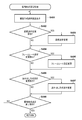
- FIG. 5 is a flowchart showing the temperature rise relaxation mode switching process of the present embodiment.
- FIG. 6 is a flowchart showing the moving image recording process of the present embodiment.
- FIG. 7 is a diagram showing an example of the imaging format setting screen of the present embodiment.
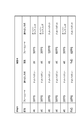
- FIG. 8 is a diagram showing an example of an imaging format that switches between waiting for shooting and during shooting in the temperature rise relaxation mode of the present embodiment.
- FIG. 1A is a front perspective view of the digital camera 100
- FIG. 1B is a rear perspective view of the digital camera 100.
- the rear display unit 101 is a display device such as an LCD provided on the back of the camera body for displaying images and various information. Further, the rear display unit 101 also has a still image reproduction after still image shooting, a moving image display during recording, and a live view display function.
- the outside viewfinder display unit 243 is a display device such as an LCD provided on the upper surface of the camera body, and displays various settings of the camera such as a shutter speed and an aperture.
- the shutter button 102 is an operation unit for giving a shooting instruction.
- the mode changeover switch 103 is a dial-type operation unit for switching various modes.
- the terminal cover 104 is a cover member that protects a connector (not shown) for connecting the external device 300 and the digital camera 100 via a cable such as USB.
- the main electronic dial 105 is a rotation operation member included in the operation unit 270 described later in FIG. 2, and by turning the main electronic dial 105, set values such as a shutter speed and an aperture can be changed.
- the power switch 106 is an operating member that switches the power of the digital camera 100 on / off.
- the sub-electronic dial 107 is also a rotation operation member included in the operation unit 270 described later in FIG. 2, and can move the selection frame, feed an image, and the like.
- the cross key 108 is also a movement instruction member included in the operation unit 270 described later in FIG. 2, and by pressing any of the four-direction buttons consisting of up, down, left, and right, the cross key 108 is pressed according to the pressed portion. Operation is possible.
- the SET button 109 is also a push button included in the operation unit 270 described later in FIG. 2, and is mainly used for determining selection items and the like.
- the live view button 110 is also a push button included in the operation unit 270 described in FIG. 2, and in the still image shooting mode, the live view (hereinafter, may be referred to as LV) display is switched on / off, and the moving image recording mode is used. Is used to instruct the start and stop of movie shooting (recording).
- the enlargement button 111 is also a push button included in the operation unit 270 described later in FIG. 2, and is an operation member for turning on / off the enlargement display during the live view and changing the enlargement ratio during the enlarged display.
- the enlargement button 111 is an operation member for enlarging the reproduced image and increasing the enlargement ratio in the reproduction mode.
- the reduction button 112 is also a push button included in the operation unit 270 described later in FIG. 2, and is an operation member for reducing the enlargement ratio of the enlarged reproduced image and reducing the screen.
- the play button 113 is also a push button included in the operation unit 270 described later in FIG. 2, and is an operation member for switching between the shooting mode and the play mode. By pressing the playback button 113 during the shooting mode, the playback mode can be entered, and the latest image among the images recorded on the recording medium 250 can be displayed on the rear display unit 101.
- the quick return mirror 212 is driven to an up position (exposure position) or a down position (live view position) by an actuator (not shown) in response to an instruction from the system control unit 201 described later in FIG.
- the communication terminal 210 is an electrical contact for the digital camera 100 to communicate with the lens unit 200 (FIG. 2).
- the peep-type eyepiece finder 216 is an optical member for confirming the focus and composition of the subject image captured through the lens unit 200 by observing the focusing screen 213 (FIG. 2).
- the lid 116 is a member that opens and closes a slot for attaching and detaching the recording medium 250 to and from the digital camera 100.
- the grip portion 115 has a shape that is easy to grip with the right hand when the user holds the digital camera 100.
- FIG. 2 the internal configuration of the digital camera 100 and the lens unit 200 of the present embodiment will be described.
- the same reference numerals are given to the configurations common to those in FIGS. 1A and 1B.
- the lens unit 200 is equipped with a photographing lens 207 and is removable from the digital camera 100.
- the photographing lens 207 is usually composed of a plurality of lenses, but here, it is shown by only one lens for simplification.
- the communication terminal 206 is an electrical contact for the lens unit 200 to communicate with the digital camera 100.
- the communication terminal 210 is an electrical contact for the digital camera 100 to communicate with the lens unit 200.
- the lens unit 200 communicates with the system control unit 201 via the communication terminal 206, the built-in lens control unit 204 controls the aperture drive circuit 202 to drive the aperture 205, and controls the AF drive circuit 203 for shooting. Focus is achieved by shifting the position of the lens 207.
- the AE sensor 217 measures the brightness of the subject captured through the lens unit 200.
- the focus detection unit 211 outputs a defocus amount to the system control unit 201, and the system control unit 201 communicates with the lens unit 200 according to the defocus amount to control the autofocus process in the phase difference detection method.
- the quick return mirror (hereinafter referred to as a mirror) 212 is driven to an up position or a down position by an actuator (not shown) in response to an instruction from the system control unit 201 at the time of exposure, live view display, and movie shooting.
- the quick return mirror 212 switches the luminous flux incident from the photographing lens 207 to the eyepiece finder 216 or the imaging unit 222.
- the quick return mirror 212 is usually urged in the down position to reflect the luminous flux and guide the luminous flux to the eyepiece viewfinder 216, but for exposure and live view display, it jumps upward so as to guide the luminous flux to the imaging unit 222. Escape from the luminous flux (up position).
- the quick return mirror 212 has a half mirror at the center so that a part of the light flux is transmitted and incident on the focus detection unit 211.
- the focal plane shutter 221 can freely control the exposure time in the imaging unit 222 according to the instruction of the system control unit 201.
- the image pickup unit 222 is an image sensor composed of an image pickup element such as a CCD or CMOS that converts a subject image into an electric signal.
- the A / D converter 223 converts the analog signal output from the imaging unit 222 into a digital signal.
- the image processing unit 224 performs resizing processing such as predetermined pixel interpolation and reduction and color conversion processing on the data from the A / D converter 223 or the data from the memory control unit 215. Further, the image processing unit 224 performs a predetermined calculation process using the captured image data, and the system control unit 201 performs exposure control and distance measurement control based on the calculation result. As a result, TTL (through-the-lens) AF (autofocus) processing, AE (auto-exposure) processing, and EF (flash pre-flash) processing are performed. Further, the image processing unit 224 performs a predetermined calculation process using the captured image data, and also performs a TTL method AWB (auto white balance) process based on the calculation result.
- TTL through-the-lens
- AF autofocus
- AE auto-exposure
- EF flash pre-flash
- the digital data output from the A / D converter 223 is written directly to the memory 232 via the image processing unit 224 and the memory control unit 215, or via the memory control unit 215.
- the memory 232 includes image data obtained from the image pickup unit 222 and the A / D converter 223, display data for display on the rear display unit 101, and display or recording data for output to the external device 300. To store.
- the memory 232 has a storage capacity sufficient for storing a predetermined number of still images, moving images for a predetermined time, and audio. Further, the memory 232 also serves as a memory (video memory) for displaying an image.
- the D / A converter 219 converts the image display data stored in the memory 232 into an analog signal and supplies it to the rear display unit 101.
- the display image data written in the memory 232 is displayed by the rear display unit 101 via the D / A converter 219.
- the rear display unit 101 displays according to the analog signal from the D / A converter 219. In this way, the digital signal stored in the memory 232 is converted into an analog signal, and the digital signal is sequentially transferred to the rear display unit 101 for display, thereby realizing the electronic viewfinder (EVF) function and displaying the live view (through image). Display) can be performed.
- EMF electronic viewfinder
- the display unit 241 in the viewfinder displays a frame indicating the AF point (AF position) at which AF processing is currently being performed, an icon indicating the setting state of the camera, and the like via the display unit drive circuit 242 in the viewfinder. ..
- the user can check the AF position and the setting state of the camera through the optical viewfinder (OVF) that can visually recognize the subject image captured by the lens unit 200 by looking into the eyepiece viewfinder 216.
- OVF optical viewfinder
- the outside viewfinder display unit 243 displays various camera settings such as shutter speed and aperture via the outside viewfinder display unit drive circuit 244.
- the external output I / F 290 supplies the display or recording video data (still image data or moving image data) stored in the memory 232 to the external device 300 as a digital signal.
- a video signal, an audio signal, and a control signal are output according to a communication protocol conforming to the HDMI (registered trademark) (High-Definition Multimedia Interface) standard.
- HDMI registered trademark
- the external device 300 is, for example, a display device or a recording device compatible with 4K or 8K.
- the external output I / F 290 is not limited to HDMI (registered trademark), and may be SDI or USB.
- the non-volatile memory 256 is, for example, EEPROM that can be electrically erased and recorded.
- the non-volatile memory 256 stores constants, programs, and the like for the operation of the system control unit 201.
- the program referred to here is a program for executing various flowcharts described later.
- the system control unit 201 includes a CPU and an MPU that control the entire digital camera 100, and executes a program stored in the non-volatile memory 256 to realize each process of the flowchart described later.
- the system memory 252 is a RAM or the like, and is also used as a work memory for expanding constants and variables for operation of the system control unit 201, programs read from the non-volatile memory 256, and the like.
- the system control unit 201 also performs display control by controlling the memory 232, the D / A converter 219, the rear display unit 101, the external output I / F 290, and the like.
- the system timer 253 is a time measuring unit that measures the time used for various controls and the time of the built-in clock.
- the mode changeover switch 103, the first shutter switch 261 and the second shutter switch 262, and the operation unit 270 are operation means for inputting various instructions to the system control unit 201.
- the mode changeover switch 103 switches the operation mode of the system control unit 201 to any one of a still image shooting mode, a moving image recording mode, and a playback mode.
- the still image shooting mode includes, for example, an auto shooting mode, an auto scene determination mode, a manual mode, an aperture priority mode (Av mode), and a shutter speed priority mode (Tv mode).
- the still image shooting mode includes, for example, various scene modes, program AE mode, custom mode, etc., which are shooting settings for each shooting scene.
- the mode changeover switch 103 directly switches to any of a plurality of modes included in the still image shooting mode.
- the mode may be switched to any of the plurality of modes included in the still image shooting mode by using another operating member.
- the moving image recording mode and the playback mode may include a plurality of modes.
- the moving image recording mode includes a temperature rise relaxation mode (eco mode) that reduces a temperature rise due to heat generation caused by internal processing of the digital camera 100.
- the switch 261 is turned on by a so-called half-press (shooting preparation instruction) during the operation of the shutter button 102 provided on the digital camera 100, and generates the first shutter switch signal SW1.
- the system control unit 201 Upon receiving the first shutter switch signal SW1, the system control unit 201 starts AF processing, AE processing, AWB processing, EF processing, and the like by the image processing unit 224.
- the second shutter switch 262 is turned on when the operation of the shutter button 102 is completed, so-called full pressing (shooting instruction), and the second shutter switch signal SW2 is generated.
- the system control unit 201 starts a series of shooting processes from reading the signal from the imaging unit 222 to writing the image data to the recording medium 250 by the second shutter switch signal SW2.
- the operation unit 270 By selecting an item for setting various functions displayed on the rear display unit 101 and an item indicating a set value, the operation unit 270 is appropriately assigned a function for each scene and acts as various function buttons. do.
- the function buttons include a menu button 270e, an end button, a back button, an image feed button, a jump button, a narrowing down button, an attribute change button, and the like.
- the menu button 270e when the menu button 270e is pressed, various settable menu screens are displayed on the rear display unit 101. The user can intuitively make various settings by using the menu screen displayed on the rear display unit 101, the cross key 108, and the SET button 109.
- the operation unit 270 includes various operation members such as switches, buttons, and a touch panel that receive various operations from the user, and includes at least the following operation members.
- the cross key 108 is a direction button on which the up, down, right, and left parts of the cross key 108 can be pushed.
- the operation unit is described as an integral unit, but the upper button, the lower button, the right button, and the left button may be independent buttons.
- the operation unit 270 includes an operation member such as a dedicated connection button for starting data communication with the external device 300 via the external output I / F 290.
- the power supply control unit 280 is composed of a battery detection circuit, a DC-DC converter, a switch circuit for switching a block to be energized, and the like, and detects whether or not a battery is installed, the type of battery, and the remaining battery level. Further, the power supply control unit 280 controls the DC-DC converter based on the detection result and the instruction of the system control unit 201, and supplies a necessary voltage to each unit including the recording medium 250 for a necessary period.
- the power supply unit 230 includes a primary battery such as an alkaline battery or a lithium battery, a secondary battery such as a NiCd battery, a NiMH battery, or a Li ion battery, an AC adapter, or the like.
- the recording medium I / F 218 is an interface with a recording medium 250 such as a memory card or a hard disk.
- the recording medium 250 is a recording medium such as a memory card for recording a captured image, and is composed of a semiconductor memory, a magnetic disk, or the like.
- the communication unit 254 is connected by a wireless or wired cable to transmit and receive video signals and audio signals.
- the communication unit 254 can also be connected to a wireless LAN (Local Area Network) and the Internet.
- the communication protocol is assumed to be FTP (File Transfer Protocol), PTP (Picture Transfer Protocol), or the like, but it is not particularly limited in this embodiment because it is assumed that the existing technology is used.
- the communication unit 254 can transmit an image (including a through image) captured by the image pickup unit 222 and an image file recorded on the recording medium 250 to the external device 300, and the image file and various other types from the external device 300. Information can be received.
- the posture detection unit 255 detects the posture of the digital camera 100 with respect to the direction of gravity. Based on the posture detected by the posture detection unit 255, whether the image taken by the image pickup unit 222 is an image taken by holding the digital camera 100 horizontally or an image taken by holding the digital camera 100 vertically. It can be discriminated.
- the system control unit 201 can add orientation information according to the posture detected by the posture detection unit 255 to the image file of the image captured by the image pickup unit 222, or can rotate and record the image.
- an acceleration sensor, a gyro sensor, or the like can be used as the posture detection unit 255.
- the rear display unit 101 is provided with a touch panel 270a having a touch sensor capable of detecting a touch operation on the display screen.
- the touch panel 270a is an input device that is superposed on the display screen of the rear display unit 101 and is configured in a plane so that coordinate information corresponding to the contacted position is output.
- the system control unit 201 can detect the following operations on the touch panel 270a. Touching the touch panel 270a with a finger or pen (touchdown). The touch panel 270a is being touched with a finger or a pen (touch-on). Moving while touching the touch panel 270a with a finger or pen (move). The finger or pen that was touching the touch panel 270a was released (touch-up).
- a state in which nothing is touched on the touch panel 270a (touch-off). Continuously performing touchdown and touchup on the touch panel 270a with a finger or a pen is called a tap.
- These operations and the position coordinates where the finger or pen is touching the touch panel are notified to the system control unit 201, and the system control unit 201 determines what kind of operation has been performed on the touch panel based on the notified information. do.
- the moving direction of the finger or pen moving on the touch panel 270a can also be determined for each of the vertical component and the horizontal component of the touch panel 270a based on the change in the position coordinates.
- the touch panel 270a may be any of various types of touch panels such as a resistive film method, a capacitance method, a surface acoustic wave method, an infrared method, an electromagnetic induction method, an image recognition method, and an optical sensor method. good.
- the present invention can be applied not only to the image pickup device main body but also to a control device that communicates with the image pickup device (including a network camera) via wired or wireless communication and remotely controls the image pickup device.
- a control device that communicates with the image pickup device (including a network camera) via wired or wireless communication and remotely controls the image pickup device.
- a device for remotely controlling the image pickup device for example, there are devices such as smartphones, tablet PCs, and desktop PCs.
- the image pickup device can be controlled remotely by notifying the image pickup device of commands for performing various operations and settings from the control device side based on the operations performed on the control device side and the processes performed on the control device side. be.
- the live view image taken by the imaging device may be received via wired or wireless communication and displayed on the control device side.
- the present invention is applied to a digital camera has been described as an example, but this is not limited to this example. That is, it is equipped with a display unit such as a PDA (Personal Digital Assistant), a mobile phone terminal, a portable image viewer, a printer device equipped with a display, a digital photo frame, a music player, a game machine, and an electronic book reader, and data is transmitted to an external device.
- a display unit such as a PDA (Personal Digital Assistant), a mobile phone terminal, a portable image viewer, a printer device equipped with a display, a digital photo frame, a music player, a game machine, and an electronic book reader, and data is transmitted to an external device.
- the present invention is applicable as long as it is a transferable device.
- each flowchart of FIGS. 3 to 6 is realized by expanding the program recorded in the non-volatile memory 256 to the system memory 252 and executing it by the system control unit 201. Further, the process of FIG. 3 is started when the power of the digital camera 100 is turned on and the moving image recording mode is set.
- the temperature rise mitigation function suppresses the processing load of the imaging unit 222 of the digital camera 100 and the power consumption of the battery, and reduces the temperature rise due to heat generation inside the device. This is a function that reduces the processing when capturing images. Specifically, when the temperature rise relaxation mode is on, the image quality (resolution), frame rate, video signal reading method, etc. of the moving image output from the imaging unit 222 during shooting standby (during movie recording), etc. To reduce.
- the system control unit 201 receives the user operation by the operation unit 270, determines whether or not the image pickup format setting instruction has been given, and if the image pickup format setting instruction is given, proceeds to S302 and proceeds to the image pickup format setting instruction. If is not performed, the process proceeds to S303.
- the system control unit 201 performs the imaging format setting process described later in FIG.
- the system control unit 201 receives the user operation by the operation unit 270, determines whether or not the temperature rise relaxation setting instruction has been given, and if the setting instruction of the temperature rise relaxation function is given, proceeds to S304. If the setting instruction of the temperature rise relaxation function is not given, the process proceeds to S306.
- the system control unit 201 determines whether or not display data or recording data is output to the external device 300 by the external output I / F 290, and if it is output, proceeds to S306 and outputs the data. If not, proceed to S305.
- the system control unit 201 changes the temperature rise relaxation function on or off according to the user operation received by the operation unit 270, and stores it in the system memory 252.
- the system control unit 201 changes the operation setting of the imaging unit 222 according to the imaging format setting set in S302, and displays the live view image on the rear display unit 101.
- the system control unit 201 determines the setting state of the temperature rise relaxation function, proceeds to S308 when the temperature rise relaxation function is on, and proceeds to S310 when the temperature rise relaxation function is off.
- the system control unit 201 determines whether or not display data or recording data is output to the external device 300 by the external output I / F 290, and if it is output, proceeds to S310 and outputs the data. If not, the process proceeds to S309.
- the switching to the temperature rise relaxation mode at the time of external output is performed by both the output destination display device and the rear display unit 101 of the digital camera 100 even when one screen is set to display only on the output destination display device. It is prohibited even when the two screens to be displayed on are set.
- the system control unit 201 performs the temperature rise relaxation mode switching process described later in FIG.
- the system control unit 201 determines whether or not the operation unit 270 accepts the user operation and gives an instruction to start moving image recording such as pressing the live view button 110, and when the instruction to start moving image recording is given. Goes to S311 and if not done, goes to S312.
- the system control unit 201 determines whether the operation unit 270 accepts the user operation and gives a process end instruction such as turning off the power switch 106, and ends the process if the process end instruction is given. If not, the process returns to S301 and the process is repeated.
- the system control unit 201 displays the image pickup format setting screen 700 shown in FIG. 7 on the rear display unit 101.
- the user can set the image quality setting item 701 and the frame rate setting item 702 displayed on the imaging format setting screen of FIG. Arbitrary settings can be selected for each of the video compression method setting item 703 and the signal reading method setting item 704.
- the image quality setting item 701 includes video resolution options such as 4K, 8K, and FHD.
- the frame rate setting item 702 includes options such as 120 FPS (frames per second), 60 FPS, and 30 FPS.
- the video compression method setting item 703 has options of All-I and IPB for each image quality setting item 701.
- the setting item 704 of the signal reading method includes options such as an oversampling method (Over) and a dot-by-dot method (Dot).
- the oversampling method is a method of reading from the image sensor with all pixels and then converting to the set image quality
- the dot-by-dot method is a method of reading only the set image quality area from the image sensor.
- the system control unit 201 receives the user operation by the operation unit 270, determines whether or not the image quality setting change instruction has been given, and if the image quality setting change instruction is given, proceeds to S403 and is not performed. If so, proceed to S404.
- the user can select any setting from the image quality setting item 701 on the image pickup format setting screen 700 of FIG. 7.
- the system control unit 201 changes the image quality setting according to the image quality setting change instruction received in S402, and stores it in the system memory 252.
- the system control unit 201 receives the user operation by the operation unit 270, determines whether or not the frame rate setting change instruction has been given, and if the frame rate setting change instruction is given, proceeds to S405 and is performed. If not, proceed to S406.
- the system control unit 201 changes the frame rate setting according to the frame rate change instruction received in S404, and stores it in the system memory 252.
- the system control unit 201 receives the user operation by the operation unit 270, determines whether or not the read method change instruction has been given, and if the read method change instruction is given, proceeds to S407 and is not performed. If so, proceed to S408.
- the system control unit 201 changes the read method setting according to the read method change instruction received in S406 and stores it in the system memory 252.
- the system control unit 201 determines whether or not the operation unit 270 receives the user operation and has given the imaging format setting end instruction, and if the imaging format setting end instruction has been given, the process ends and the line is executed. If not, the process returns to S401 and the process is repeated.
- the system control unit 201 determines whether or not the image quality setting stored in the system memory 252 is 8K, proceeds to S502 if it is 8K, and proceeds to S503 if it is not 8K.
- the system control unit 201 switches the operation setting of the imaging unit 222 to the 4K setting.
- the system control unit 201 determines whether or not the frame rate setting stored in the system memory 252 is 30P, proceeds to S505 if it is 30P, and proceeds to S504 if it is not 30P.
- the system control unit 201 switches the operation setting of the imaging unit 222 to the setting of 30P.
- the system control unit 201 determines whether or not the read method setting stored in the system memory 252 is the oversampling method, proceeds to S506 in the case of the oversampling method, and proceeds to S506 in the case of the oversampling method. End the process.
- the system control unit 201 switches the operation setting of the imaging unit 222 to the dot-by-dot method setting.
- FIG. 8 illustrates a part of the imaging format setting that can be switched between standby and shooting in the temperature rise relaxation mode.
- the temperature rise relaxation function when the temperature rise relaxation function is set to ON, at least one of the image quality setting, the frame rate setting, and the readout method setting is changed in the direction of decreasing during the shooting standby. As a result, it is possible to reduce the temperature inside the digital camera 100 from becoming high.
- the system control unit 201 determines whether or not the mode has been switched to the temperature rise relaxation mode, proceeds to S602 if the mode has been switched to the temperature rise relaxation mode, and proceeds to S603 if the mode has not been switched.
- the system control unit 201 switches the operation setting of the image pickup unit 222 according to the image pickup format setting stored in the system memory 252.
- the system control unit 201 performs moving image recording start processing such as starting signal reading from the imaging unit 222.
- the system control unit 201 generates a moving image file from the signal read from the imaging unit 222 and performs a moving image recording process of writing the moving image file to the recording medium 250.
- the system control unit 201 determines whether or not the operation unit 270 accepts the user operation and gives an instruction to stop moving image recording such as pressing the live view button 110, and when the instruction to stop moving image recording is given. Proceeds to S606, and if not, proceeds to S604.
- the system control unit 201 performs moving image recording stop processing such as stopping signal reading from the imaging unit 222.
- the process may be interrupted in the middle of the process.
- the digital camera 100 when the digital camera 100 can be switched to the temperature rise relaxation mode and can be executed, when the external output is not performed, the temperature rise relaxation function is set or the temperature rise relaxation mode is set.
- the switching of the digital camera 100 is permitted to reduce the temperature inside the digital camera 100 from becoming high.
- external output when external output is in progress, it is possible to suppress the deterioration of the image quality of the image output externally by prohibiting the setting of the temperature rise relaxation function and switching to the temperature rise relaxation mode, and when recording with a recording device or It is possible to reduce inconvenience when displaying on a display device.
- the present invention supplies a program that realizes one or more functions of the above-described embodiment to a system or device via a network or storage medium, and one or more processors in the computer of the system or device reads and executes the program. It can also be realized by the processing to be performed. It can also be realized by a circuit (for example, ASIC) that realizes one or more functions.
- a circuit for example, ASIC
Landscapes
- Engineering & Computer Science (AREA)
- Multimedia (AREA)
- Signal Processing (AREA)
- Physics & Mathematics (AREA)
- General Physics & Mathematics (AREA)
- Human Computer Interaction (AREA)
- Studio Devices (AREA)
- Indication In Cameras, And Counting Of Exposures (AREA)
Abstract
Description
以下に、本発明のデータ転送装置を、静止画や動画を撮影可能なデジタル一眼レフカメラに適用した実施の形態について、添付図面を参照して詳細に説明する。
本発明は、上述の実施形態の1以上の機能を実現するプログラムを、ネットワーク又は記憶媒体を介してシステム又は装置に供給し、そのシステム又は装置のコンピュータにおける1つ以上のプロセッサがプログラムを読出し実行する処理でも実現可能である。また、1以上の機能を実現する回路(例えば、ASIC)によっても実現可能である。
Claims (17)
- 撮像手段により得られた映像を表示する表示手段と、
前記映像を外部機器に出力する出力手段と、
撮影待機中は撮影中と異なる撮像形式設定で前記映像を撮像する第1の動作と、撮影待機中か撮影中かにかかわらず同じ撮像形式設定で前記映像を撮像する第2の動作と、を含む複数の動作を切り替えて実行可能な処理手段と、
前記出力手段により前記外部機器への前記映像の出力が行われていない場合は、前記処理手段が前記第1の動作を実行することを許可し、
前記出力手段により前記外部機器への前記映像の出力が行われている場合は、前記処理手段が前記第1の動作を実行することを禁止する制御手段と、を有することを特徴とする撮像装置。 - 前記第2の動作から前記第1の動作に変更するユーザ操作を受け付ける操作手段をさらに有し、
前記制御手段は、前記出力手段により前記外部機器への前記映像の出力が行われていない場合に前記ユーザ操作を受け付けたことに応じて前記第2の動作から前記第1の動作に変更することを特徴とする請求項1に記載の撮像装置。 - 前記制御手段は、前記出力手段により前記外部機器への前記映像の出力が行われていない場合は、前記第2の動作から前記第1の動作への切り替え、または、前記第1の動作から前記第2の動作への切り替えを許可し、
前記出力手段により前記外部機器への前記映像の出力が行われている場合は、前記第2の動作から前記第1の動作への切り替えを禁止することを特徴とする請求項1に記載の撮像装置。 - 前記撮像形式設定を設定可能な設定手段をさらに有することを特徴とする請求項1から3のいずれか1項に記載の撮像装置。
- 前記撮像形式設定は、前記映像の画質、フレームレートおよび読み出し方式の少なくとも1つを含むことを特徴とする請求項1から4のいずれか1項に記載の撮像装置。
- 前記制御手段は、前記第1の動作において前記撮影中は前記設定手段の撮像形式設定に応じた処理を行い、撮影待機中は前記設定手段の撮像形式設定に対して前記映像の撮像時の処理が軽減された撮像形式設定に応じた処理を行うように制御することを特徴とする請求項4に記載の撮像装置。
- 前記第1の動作における前記撮影待機中の撮像形式設定は、前記撮影中の撮像形式設定よりも前記映像の撮像時の処理に起因する発熱を低減するような撮像形式設定であることを特徴とする請求項6に記載の撮像装置。
- 前記制御手段は、前記出力手段により前記外部機器への前記映像の出力が行われている場合は、映像の出力先の外部機器だけに映像を表示する画面設定時であっても、映像の出力先の外部機器と撮像装置の両方に映像を表示する画面設定時であっても、前記処理手段が前記第1の動作を実行することを禁止することを特徴とする請求項1から7のいずれか1項に記載の撮像装置。
- 前記表示手段は、前記撮像手段により得られた映像をライブビューとして表示することを特徴とする請求項1から8のいずれか1項に記載の撮像装置。
- 前記撮像手段により得られた映像を記録する記録手段をさらに有することを特徴とする請求項1から9のいずれか1項に記載の撮像装置。
- 前記処理手段は、前記撮像手段を有することを特徴とする請求項1から10のいずれか1項に記載の撮像装置。
- 撮像手段と、
前記撮像手段により得られた映像を表示する表示手段と、
前記映像を外部機器に出力する出力手段と、
前記出力手段により前記外部機器への映像の出力が行われていない場合は、撮影待機中は撮影中よりもフレームレートが低い前記映像を得る第1の動作を前記撮像手段に実行させ、
前記出力手段により前記外部機器への映像の出力が行われている場合は、撮影待機中か撮影中かにかかわらずフレームレートが等しい前記映像を得る第2の動作を前記撮像手段に実行させる制御手段と、を有することを特徴とする撮像装置。 - 撮像手段と、
前記撮像手段により得られた映像を表示する表示手段と、
前記映像を外部機器に出力する出力手段と、
前記出力手段により前記外部機器への映像の出力が行われていない場合は、撮影待機中は撮影中よりも画質が低い前記映像を得る第1の動作を前記撮像手段に実行させ、
前記出力手段により前記外部機器への映像の出力が行われている場合は、撮影待機中か撮影中かにかかわらず画質が等しい前記映像を得る第2の動作を前記撮像手段に実行させる制御手段と、を有することを特徴とする撮像装置。 - 撮像手段と、
前記撮像手段により得られた映像を表示する表示手段と、
前記映像を外部機器に出力する出力手段と、
前記出力手段により前記外部機器への映像の出力が行われていない場合は、撮影待機中は撮影中と異なる読み出し方式を用いて前記映像を得る第1の動作を前記撮像手段に実行させ、
前記出力手段により前記外部機器への映像の出力が行われている場合は、撮影待機中か撮影中かにかかわらず同じ読み出し方式を用いて前記映像を得る第2の動作を前記撮像手段に実行させる制御手段と、を有することを特徴とする撮像装置。 - 撮像手段により得られた映像を表示する表示手段と、前記映像を外部機器に出力する出力手段と、を有し、撮影待機中は撮影中と異なる撮像形式設定で前記映像を撮像する第1の動作と、撮影待機中か撮影中かにかかわらず同じ撮像形式設定で前記映像を撮像する第2の動作と、を含む複数の動作を切り替えて実行可能な撮像装置の制御方法であって、
前記出力手段により前記外部機器への前記映像の出力が行われていない場合は、前記撮像装置が前記第1の動作を実行することを許可し、
前記出力手段により前記外部機器への前記映像の出力が行われている場合は、前記撮像装置が前記第1の動作を実行することを禁止することを特徴とする制御方法。 - コンピュータを、請求項1から14のいずれか1項に記載された撮像装置として機能させるためのプログラム。
- コンピュータを、請求項1から14のいずれか1項に記載された撮像装置として機能させるためのプログラムを記憶したコンピュータによる読み取りが可能な記憶媒体。
Priority Applications (3)
| Application Number | Priority Date | Filing Date | Title |
|---|---|---|---|
| CN202180010398.5A CN115004684A (zh) | 2020-01-24 | 2021-01-19 | 摄像设备和控制方法 |
| BR112022013564A BR112022013564A2 (pt) | 2020-01-24 | 2021-01-19 | Aparelho de captura de imagem e método de controle |
| US17/864,516 US12003852B2 (en) | 2020-01-24 | 2022-07-14 | Image capture apparatus and control method |
Applications Claiming Priority (2)
| Application Number | Priority Date | Filing Date | Title |
|---|---|---|---|
| JP2020010328A JP7389662B2 (ja) | 2020-01-24 | 2020-01-24 | 撮像装置、制御方法、プログラムならびに記憶媒体 |
| JP2020-010328 | 2020-01-24 |
Related Child Applications (1)
| Application Number | Title | Priority Date | Filing Date |
|---|---|---|---|
| US17/864,516 Continuation US12003852B2 (en) | 2020-01-24 | 2022-07-14 | Image capture apparatus and control method |
Publications (1)
| Publication Number | Publication Date |
|---|---|
| WO2021149689A1 true WO2021149689A1 (ja) | 2021-07-29 |
Family
ID=76992977
Family Applications (1)
| Application Number | Title | Priority Date | Filing Date |
|---|---|---|---|
| PCT/JP2021/001716 WO2021149689A1 (ja) | 2020-01-24 | 2021-01-19 | 撮像装置及び制御方法 |
Country Status (5)
| Country | Link |
|---|---|
| US (1) | US12003852B2 (ja) |
| JP (1) | JP7389662B2 (ja) |
| CN (1) | CN115004684A (ja) |
| BR (1) | BR112022013564A2 (ja) |
| WO (1) | WO2021149689A1 (ja) |
Citations (4)
| Publication number | Priority date | Publication date | Assignee | Title |
|---|---|---|---|---|
| JP2007081737A (ja) * | 2005-09-13 | 2007-03-29 | Canon Inc | 撮像装置及びその制御方法 |
| JP2007134805A (ja) * | 2005-11-08 | 2007-05-31 | Canon Inc | 電子撮像装置 |
| JP2010245880A (ja) * | 2009-04-07 | 2010-10-28 | Canon Inc | 撮像装置 |
| WO2019207641A1 (ja) * | 2018-04-24 | 2019-10-31 | オリンパス株式会社 | 撮像装置、撮像装置の作動方法、およびプログラム |
Family Cites Families (10)
| Publication number | Priority date | Publication date | Assignee | Title |
|---|---|---|---|---|
| US7372999B2 (en) * | 2002-09-09 | 2008-05-13 | Ricoh Company, Ltd. | Image coder and image decoder capable of power-saving control in image compression and decompression |
| JP2006333315A (ja) | 2005-05-30 | 2006-12-07 | Sharp Corp | 表示装置 |
| CN101895687A (zh) | 2005-11-30 | 2010-11-24 | 株式会社日立制作所 | 具有省电模式的摄像装置 |
| JP2007264953A (ja) * | 2006-03-28 | 2007-10-11 | Toshiba Corp | 情報処理装置および動作制御方法 |
| US8666221B2 (en) | 2011-01-21 | 2014-03-04 | Panasonic Corporation | Imaging apparatus |
| JP2013115670A (ja) * | 2011-11-30 | 2013-06-10 | Sony Corp | 撮像装置、その制御方法およびプログラム |
| JP6652309B2 (ja) * | 2017-11-15 | 2020-02-19 | キヤノン株式会社 | 撮像装置および制御方法 |
| JP7309422B2 (ja) * | 2019-04-08 | 2023-07-18 | キヤノン株式会社 | 通信装置、その制御方法、およびそのプログラム |
| JP2023020585A (ja) * | 2021-07-30 | 2023-02-09 | キヤノン株式会社 | 電子機器および制御方法 |
| JP2023020696A (ja) * | 2021-07-30 | 2023-02-09 | キヤノン株式会社 | 電子機器および制御方法 |
-
2020
- 2020-01-24 JP JP2020010328A patent/JP7389662B2/ja active Active
-
2021
- 2021-01-19 CN CN202180010398.5A patent/CN115004684A/zh active Pending
- 2021-01-19 WO PCT/JP2021/001716 patent/WO2021149689A1/ja active Application Filing
- 2021-01-19 BR BR112022013564A patent/BR112022013564A2/pt unknown
-
2022
- 2022-07-14 US US17/864,516 patent/US12003852B2/en active Active
Patent Citations (4)
| Publication number | Priority date | Publication date | Assignee | Title |
|---|---|---|---|---|
| JP2007081737A (ja) * | 2005-09-13 | 2007-03-29 | Canon Inc | 撮像装置及びその制御方法 |
| JP2007134805A (ja) * | 2005-11-08 | 2007-05-31 | Canon Inc | 電子撮像装置 |
| JP2010245880A (ja) * | 2009-04-07 | 2010-10-28 | Canon Inc | 撮像装置 |
| WO2019207641A1 (ja) * | 2018-04-24 | 2019-10-31 | オリンパス株式会社 | 撮像装置、撮像装置の作動方法、およびプログラム |
Also Published As
| Publication number | Publication date |
|---|---|
| US12003852B2 (en) | 2024-06-04 |
| CN115004684A (zh) | 2022-09-02 |
| BR112022013564A2 (pt) | 2022-09-06 |
| JP7389662B2 (ja) | 2023-11-30 |
| JP2021118433A (ja) | 2021-08-10 |
| US20220353413A1 (en) | 2022-11-03 |
Similar Documents
| Publication | Publication Date | Title |
|---|---|---|
| JP6765956B2 (ja) | 撮像制御装置及びその制御方法 | |
| US9807296B2 (en) | Image capturing apparatus and auto focus control method therefor | |
| US9819857B2 (en) | Electronic apparatus, control method for the same, and image capturing apparatus | |
| CN108322641B (zh) | 摄像控制设备、控制方法和存储介质 | |
| JP2018133674A (ja) | 撮像装置及びその制御方法 | |
| JP5988860B2 (ja) | 撮像装置及び撮像装置の制御方法 | |
| US11178327B2 (en) | Electronic apparatus, control method for electronic apparatus, and non-transitory computer readable medium | |
| JP5506589B2 (ja) | 撮像装置及びその制御方法、プログラム、並びに記録媒体 | |
| JP2013225844A (ja) | 撮像装置及びその制御方法、プログラム、並びに記憶媒体 | |
| JP2021170066A (ja) | 表示制御装置および方法、プログラム、記憶媒体 | |
| JP7034619B2 (ja) | 撮像装置、その制御方法、およびプログラム、並びに記憶媒体 | |
| CN107040717B (zh) | 摄像控制装置及其控制方法 | |
| US11195558B2 (en) | Imaging apparatus and display control method | |
| WO2021149689A1 (ja) | 撮像装置及び制御方法 | |
| JP7250628B2 (ja) | 画像処理装置、画像処理方法およびプログラム | |
| JP2015022339A (ja) | 電子機器及びその制御方法 | |
| JP6976752B2 (ja) | 撮像装置及びその制御方法、プログラム、並びに、記憶媒体 | |
| JP2018026608A (ja) | 撮像装置、撮像装置の制御方法及びプログラム並びに記憶媒体 | |
| JP6759094B2 (ja) | 電子機器及びその制御方法 | |
| JP7171876B2 (ja) | 撮像装置及びその制御方法、並びに、プログラム | |
| JP2018113538A (ja) | 撮像装置およびその制御方法 | |
| US11115589B2 (en) | Imaging control apparatus and method for controlling imaging control apparatus | |
| JP7550520B2 (ja) | 撮像装置、制御方法、プログラムならびに記憶媒体 | |
| JP6461284B2 (ja) | 撮像装置、撮像装置の制御方法及びプログラム | |
| JP6242446B2 (ja) | 撮像装置、撮像装置の制御方法及びプログラム |
Legal Events
| Date | Code | Title | Description |
|---|---|---|---|
| 121 | Ep: the epo has been informed by wipo that ep was designated in this application |
Ref document number: 21744142 Country of ref document: EP Kind code of ref document: A1 |
|
| REG | Reference to national code |
Ref country code: BR Ref legal event code: B01A Ref document number: 112022013564 Country of ref document: BR |
|
| NENP | Non-entry into the national phase |
Ref country code: DE |
|
| ENP | Entry into the national phase |
Ref document number: 112022013564 Country of ref document: BR Kind code of ref document: A2 Effective date: 20220707 |
|
| 122 | Ep: pct application non-entry in european phase |
Ref document number: 21744142 Country of ref document: EP Kind code of ref document: A1 |