WO2021149457A1 - 画像形成装置、及び印刷物の製造方法 - Google Patents
画像形成装置、及び印刷物の製造方法 Download PDFInfo
- Publication number
- WO2021149457A1 WO2021149457A1 PCT/JP2020/048824 JP2020048824W WO2021149457A1 WO 2021149457 A1 WO2021149457 A1 WO 2021149457A1 JP 2020048824 W JP2020048824 W JP 2020048824W WO 2021149457 A1 WO2021149457 A1 WO 2021149457A1
- Authority
- WO
- WIPO (PCT)
- Prior art keywords
- unit
- printing
- recording medium
- ink
- information
- Prior art date
- Legal status (The legal status is an assumption and is not a legal conclusion. Google has not performed a legal analysis and makes no representation as to the accuracy of the status listed.)
- Ceased
Links
Images


Classifications
-
- B—PERFORMING OPERATIONS; TRANSPORTING
- B41—PRINTING; LINING MACHINES; TYPEWRITERS; STAMPS
- B41M—PRINTING, DUPLICATING, MARKING, OR COPYING PROCESSES; COLOUR PRINTING
- B41M5/00—Duplicating or marking methods; Sheet materials for use therein
- B41M5/0011—Pre-treatment or treatment during printing of the recording material, e.g. heating, irradiating
-
- B—PERFORMING OPERATIONS; TRANSPORTING
- B41—PRINTING; LINING MACHINES; TYPEWRITERS; STAMPS
- B41J—TYPEWRITERS; SELECTIVE PRINTING MECHANISMS, i.e. MECHANISMS PRINTING OTHERWISE THAN FROM A FORME; CORRECTION OF TYPOGRAPHICAL ERRORS
- B41J11/00—Devices or arrangements of selective printing mechanisms, e.g. ink-jet printers or thermal printers, for supporting or handling copy material in sheet or web form
- B41J11/0015—Devices or arrangements of selective printing mechanisms, e.g. ink-jet printers or thermal printers, for supporting or handling copy material in sheet or web form for treating before, during or after printing or for uniform coating or laminating the copy material before or after printing
- B41J11/002—Curing or drying the ink on the copy materials, e.g. by heating or irradiating
- B41J11/0021—Curing or drying the ink on the copy materials, e.g. by heating or irradiating using irradiation
- B41J11/00216—Curing or drying the ink on the copy materials, e.g. by heating or irradiating using irradiation using infrared [IR] radiation or microwaves
-
- B—PERFORMING OPERATIONS; TRANSPORTING
- B41—PRINTING; LINING MACHINES; TYPEWRITERS; STAMPS
- B41J—TYPEWRITERS; SELECTIVE PRINTING MECHANISMS, i.e. MECHANISMS PRINTING OTHERWISE THAN FROM A FORME; CORRECTION OF TYPOGRAPHICAL ERRORS
- B41J15/00—Devices or arrangements of selective printing mechanisms, e.g. ink-jet printers or thermal printers, specially adapted for supporting or handling copy material in continuous form, e.g. webs
- B41J15/04—Supporting, feeding, or guiding devices; Mountings for web rolls or spindles
-
- B—PERFORMING OPERATIONS; TRANSPORTING
- B41—PRINTING; LINING MACHINES; TYPEWRITERS; STAMPS
- B41J—TYPEWRITERS; SELECTIVE PRINTING MECHANISMS, i.e. MECHANISMS PRINTING OTHERWISE THAN FROM A FORME; CORRECTION OF TYPOGRAPHICAL ERRORS
- B41J2/00—Typewriters or selective printing mechanisms characterised by the printing or marking process for which they are designed
- B41J2/005—Typewriters or selective printing mechanisms characterised by the printing or marking process for which they are designed characterised by bringing liquid or particles selectively into contact with a printing material
- B41J2/01—Ink jet
- B41J2/135—Nozzles
- B41J2/165—Prevention or detection of nozzle clogging, e.g. cleaning, capping or moistening for nozzles
- B41J2/16505—Caps, spittoons or covers for cleaning or preventing drying out
- B41J2/16508—Caps, spittoons or covers for cleaning or preventing drying out connected with the printer frame
-
- B—PERFORMING OPERATIONS; TRANSPORTING
- B41—PRINTING; LINING MACHINES; TYPEWRITERS; STAMPS
- B41J—TYPEWRITERS; SELECTIVE PRINTING MECHANISMS, i.e. MECHANISMS PRINTING OTHERWISE THAN FROM A FORME; CORRECTION OF TYPOGRAPHICAL ERRORS
- B41J2/00—Typewriters or selective printing mechanisms characterised by the printing or marking process for which they are designed
- B41J2/005—Typewriters or selective printing mechanisms characterised by the printing or marking process for which they are designed characterised by bringing liquid or particles selectively into contact with a printing material
- B41J2/01—Ink jet
- B41J2/135—Nozzles
- B41J2/165—Prevention or detection of nozzle clogging, e.g. cleaning, capping or moistening for nozzles
- B41J2/16517—Cleaning of print head nozzles
- B41J2/16535—Cleaning of print head nozzles using wiping constructions
-
- B—PERFORMING OPERATIONS; TRANSPORTING
- B41—PRINTING; LINING MACHINES; TYPEWRITERS; STAMPS
- B41J—TYPEWRITERS; SELECTIVE PRINTING MECHANISMS, i.e. MECHANISMS PRINTING OTHERWISE THAN FROM A FORME; CORRECTION OF TYPOGRAPHICAL ERRORS
- B41J2/00—Typewriters or selective printing mechanisms characterised by the printing or marking process for which they are designed
- B41J2/005—Typewriters or selective printing mechanisms characterised by the printing or marking process for which they are designed characterised by bringing liquid or particles selectively into contact with a printing material
- B41J2/01—Ink jet
- B41J2/21—Ink jet for multi-colour printing
- B41J2/2107—Ink jet for multi-colour printing characterised by the ink properties
- B41J2/2114—Ejecting specialized liquids, e.g. transparent or processing liquids
-
- B—PERFORMING OPERATIONS; TRANSPORTING
- B41—PRINTING; LINING MACHINES; TYPEWRITERS; STAMPS
- B41J—TYPEWRITERS; SELECTIVE PRINTING MECHANISMS, i.e. MECHANISMS PRINTING OTHERWISE THAN FROM A FORME; CORRECTION OF TYPOGRAPHICAL ERRORS
- B41J2/00—Typewriters or selective printing mechanisms characterised by the printing or marking process for which they are designed
- B41J2/005—Typewriters or selective printing mechanisms characterised by the printing or marking process for which they are designed characterised by bringing liquid or particles selectively into contact with a printing material
- B41J2/01—Ink jet
- B41J2/135—Nozzles
- B41J2/165—Prevention or detection of nozzle clogging, e.g. cleaning, capping or moistening for nozzles
- B41J2/16517—Cleaning of print head nozzles
- B41J2/16552—Cleaning of print head nozzles using cleaning fluids
-
- B—PERFORMING OPERATIONS; TRANSPORTING
- B41—PRINTING; LINING MACHINES; TYPEWRITERS; STAMPS
- B41J—TYPEWRITERS; SELECTIVE PRINTING MECHANISMS, i.e. MECHANISMS PRINTING OTHERWISE THAN FROM A FORME; CORRECTION OF TYPOGRAPHICAL ERRORS
- B41J2/00—Typewriters or selective printing mechanisms characterised by the printing or marking process for which they are designed
- B41J2/005—Typewriters or selective printing mechanisms characterised by the printing or marking process for which they are designed characterised by bringing liquid or particles selectively into contact with a printing material
- B41J2/01—Ink jet
- B41J2/135—Nozzles
- B41J2/165—Prevention or detection of nozzle clogging, e.g. cleaning, capping or moistening for nozzles
- B41J2/16585—Prevention or detection of nozzle clogging, e.g. cleaning, capping or moistening for nozzles for paper-width or non-reciprocating print heads
-
- B—PERFORMING OPERATIONS; TRANSPORTING
- B41—PRINTING; LINING MACHINES; TYPEWRITERS; STAMPS
- B41J—TYPEWRITERS; SELECTIVE PRINTING MECHANISMS, i.e. MECHANISMS PRINTING OTHERWISE THAN FROM A FORME; CORRECTION OF TYPOGRAPHICAL ERRORS
- B41J2203/00—Embodiments of or processes related to the control of the printing process
- B41J2203/01—Inspecting a printed medium or a medium to be printed using a sensing device
- B41J2203/011—Inspecting the shape or condition, e.g. wrinkled or warped, of a medium to be printed before printing on it
Definitions
- the present invention relates to an image forming apparatus and a method for manufacturing a printed matter, and particularly relates to a technique for performing additional printing on a recording medium on which an image is printed in advance.
- Patent Document 1 describes a card processing system that partially prints a predetermined content such as a barcode on a card on which nothing is printed and a card on which a predetermined print such as a pattern is printed on a base. ing.
- the card processing system described in Patent Document 1 includes a transport unit for transporting cards, a pretreatment unit that pretreats a part of the surface of the card transported by the transport unit, and a card transported by the transport unit. It is provided with a printing unit that prints on a portion of the surface that has been pretreated by the pretreatment unit. According to the system described in Patent Document 1, since the coating layer is formed by the pretreatment only on a part of the surface of the card, it is possible to suppress the adverse effect of the coating layer in the post-process as much as possible.
- the quality of preprocessing performed before printing differs depending on the transport conditions, printing conditions, or recording medium conditions.
- the quality of pretreatment differs because the surface state of the card differs depending on the presence or absence of the underlying pattern and the underlying pattern. Therefore, there is a problem that printing cannot always be performed with the optimum processing quality.
- the quality of post-processing performed after printing There is a similar problem with the quality of post-processing performed after printing.
- the present invention has been made in view of such circumstances, and an object of the present invention is to provide an image forming apparatus that always forms an image with the optimum processing quality, and a method for manufacturing a printed matter.
- one aspect of the image forming apparatus is to apply ink to a transport unit that transports the recording medium in the transport direction and a printing surface of the transport unit that is arranged to face the transport unit and is transported.
- a printing unit that prints by printing
- a processing unit that is arranged facing the transport unit and processes the recording medium to be transported
- a moving unit that varies the distance between the printing unit and the processing unit in the transport direction.
- An information acquisition unit that acquires at least one of information on the transfer speed of the recording medium in the transfer unit, information on the amount of ink applied in the printing unit, and information on the surface state of the print surface of the recording medium, and the acquired information.
- An image forming apparatus including a distance control unit that controls a distance based on the above.
- At least one of information on the transfer speed of the recording medium in the transfer unit, information on the amount of ink applied in the printing unit, and information on the surface state of the print surface of the recording medium is acquired and acquired. Since the distance between the printing unit and the processing unit in the transport direction is controlled based on the information obtained, the image can always be formed with the optimum processing quality.
- An image is pre-printed on the printing surface of the recording medium before printing by the printing unit and processing by the processing unit, and the information acquisition unit determines the density of the pre-printed image as information on the surface state of the printing surface of the recording medium. It is preferable that the distance control unit acquires the above information and increases the distance between the processing unit and the printing unit in the transport direction as the acquired density becomes higher. As a result, the image can be formed with the optimum processing quality regardless of the surface condition of the print surface of the recording medium.
- the information acquisition unit may acquire information on the density of a region of the pre-printed image to which ink is applied in the printing unit as information on the surface state of the print surface of the recording medium.
- An image is pre-printed on the printing surface of the recording medium before printing by the printing unit and processing by the processing unit, and the information acquisition unit electronically prints the pre-printed image as information on the surface state of the printing surface of the recording medium.
- the distance control unit prints the pre-printed image using an electrophotographic or energy ray curable ink. In the case of the image, it is preferable to reduce the distance between the printing unit and the processing unit in the transport direction. As a result, the image can be formed with the optimum processing quality regardless of the surface condition of the print surface of the recording medium.
- the information acquisition unit acquires information on the transfer speed of the recording medium in the transfer unit, and the distance control unit increases the distance as the acquired transfer speed is faster. As a result, the image can be formed with the optimum processing quality regardless of the transport speed.
- the information acquisition unit acquires information on the amount of ink applied in the printing unit, and the distance control unit reduces the distance as the acquired amount of ink applied increases. As a result, the image can be formed with the optimum processing quality regardless of the amount of ink applied.
- the printing unit and the processing unit can be moved in the width direction intersecting the transport direction, the printing unit can print on a part of the recording medium, and the processing unit can print on a part of the recording medium. It is preferable that the treatment is possible. By printing and processing a part of the recording medium, it is effective without waste in the case of reprint printing in which it is not necessary to print on the entire surface of the recording medium.
- the printing unit and the processing unit can be moved independently in the width direction. As a result, the weight of the printing unit can be reduced.
- the position accuracy of the movement of the processing unit in the width direction is lower than the position accuracy of the movement of the printing unit in the width direction. Since the processing unit does not require highly accurate position adjustment, it is possible to reduce the cost by coarsening the position accuracy.
- the printing unit is arranged adjacent to the ink ejection head that ejects ink from the nozzle in the width direction of the transport unit, and wipes the nozzle surface on which the nozzle of the ink ejection head is arranged, and the width direction of the transport unit.
- the moving unit includes a capping unit which is arranged adjacent to the ink ejection head and moisturizes the nozzle surface of the ink ejection head, and the moving unit varies in distance by moving the processing unit in the transport direction. As a result, the distance can be changed without moving the cleaning unit and the capping unit in the transport direction.
- the processing unit is arranged on the upstream side of the printing unit in the transport direction, and the pretreatment liquid that chemically reacts with the applied ink is applied to the transferred recording medium, and the applied ink permeates the printing surface. It is preferable to include a pretreatment unit that performs at least one pretreatment of irradiation of energy light that promotes the treatment and surface modification that suppresses the spread of the applied ink on the printing surface. This makes it possible to appropriately preprocess the recording medium.
- the processing unit is arranged on the downstream side in the transport direction from the printing unit, and at least one of irradiation of energy light for curing the applied ink and drying of the applied ink on the transferred recording medium. It is preferable to include a post-treatment unit for post-treatment. This makes it possible to appropriately preprocess the recording medium.
- one aspect of the method for manufacturing printed matter is a transport process in which a recording medium is transported in a transport direction by a transport unit, and a recording medium that is transported by a printing unit arranged opposite to the transport unit.
- a printing process in which ink is applied to the printing surface of the printing surface a processing process in which processing is performed on a recording medium to be conveyed by a processing unit arranged opposite to the transfer unit, and a recording medium in the transfer unit.
- At least one of information on the transfer speed of the recording medium in the transfer unit, information on the amount of ink applied in the printing unit, and information on the surface state of the print surface of the recording medium is acquired and acquired. Since the distance between the printing unit and the processing unit in the transport direction is controlled based on the information obtained, the image can always be formed with the optimum processing quality.
- an image can always be formed with the optimum processing quality.
- FIG. 1 is a perspective view of the image forming apparatus.
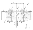
- FIG. 2 is a top view of the image forming apparatus.
- FIG. 3 is a block diagram showing an electrical configuration of the image forming apparatus.
- FIG. 4 is a flowchart showing a process of a method for manufacturing a printed matter.
- FIG. 5 is a perspective view of an image forming apparatus according to another embodiment.
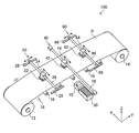
- FIG. 1 is a perspective view of the image forming apparatus 100 according to the present embodiment. Further, FIG. 2 is a top view of the image forming apparatus 100. In FIGS. 1 and 2, the X, Y, and Z directions are orthogonal to each other, the X and Y directions are horizontal, and the Z direction is vertical.
- the image forming apparatus 100 is an inkjet printing apparatus that prints an image by applying ink to a long recording medium P.
- the recording medium P various media such as paper, non-woven fabric, vinyl chloride, synthetic chemical fiber, polyethylene, polyester, tarpaulin, etc. can be used regardless of the material, and regardless of the permeable medium or the non-permeable medium. ..
- the recording medium P according to the present embodiment has an image printed on the printing surface in advance.
- the printing method of the pre-printed image is not particularly limited, and examples thereof include inkjet printing, offset printing, and electrophotographic.
- the image forming apparatus 100 manufactures a printed matter by performing additional printing on a part of the printed surface of the recording medium P.
- the image forming apparatus 100 is not limited to the additional printing, and may print on the recording medium P in which the image is not printed on the printing surface.
- the image forming apparatus 100 includes a transmission reel 12, a take-up reel 14, a plurality of pass rollers 16, a pre-processing unit 20, a printing unit 40, a post-processing unit 60, and the like. To be equipped with.
- the delivery reel 12 is rotatably supported by a side wall (not shown).
- a recording medium P on which an image is pre-printed on the printing surface is wound on the delivery reel 12 in a roll shape.
- a delivery motor (not shown) that rotationally drives the delivery reel 12 is connected to the delivery reel 12.
- the take-up reel 14 is rotatably supported by a side wall (not shown). One end of the recording medium P is connected to the take-up reel 14. A take-up motor (not shown) that rotationally drives the take-up reel 14 is connected to the take-up reel 14.
- the plurality of pass rollers 16 are arranged along the transport path of the recording medium P from the transmission reel 12 to the take-up reel 14.
- the delivery reel 12, the take-up reel 14, and the pass roller 16 constitute a transfer unit 18 that conveys the recording medium P in the Y direction, which is the transfer direction.
- the transport unit 18 guides the recording medium P by a plurality of pass rollers 16 along the transport path from the transmission reel 12 to the take-up reel 14, and transports the recording medium P in a roll-to-roll manner.
- the transport unit 18 includes a transport speed detection unit (not shown) for detecting the sales promotion speed of the recording medium P, and an in-line sensor (not shown) for capturing an image pre-printed on the recording medium P. You may prepare.
- the transport unit 18 transports the recording medium P from the transmission reel 12 to the take-up reel 14 in a fixed direction (Y direction), but it is saved by folding back the traveling direction of the recording medium P by a plurality of pass rollers 16. Space may be achieved.
- the pre-processing unit 20 In the transport path of the recording medium P, the pre-processing unit 20, the printing unit 40, and the post-processing unit 60 are arranged in order from the upstream side in the transport direction of the recording medium P, respectively, facing the transport unit 18.
- the preprocessing unit 20 (an example of the processing unit) is arranged on the upstream side of the printing unit 40 in the transport direction of the recording medium P.
- the preprocessing unit 20 performs preprocessing on the recorded recording medium P to be conveyed.
- the preprocessing unit 20 can preprocess a part of the recording medium P.
- the pretreatment unit 20 applies a pretreatment liquid that chemically reacts with the ink applied in the printing unit 40 to the recording medium P conveyed by the transfer unit 18, and applies the pretreatment liquid that chemically reacts with the ink applied in the printing unit 40 to the printing surface of the ink applied in the printing unit 40. At least one of the pretreatments of irradiation of energy light that promotes the penetration of the ink and surface modification that suppresses the spread of the ink applied in the printing unit 40 on the printing surface is performed.
- the pretreatment liquid is applied will be described.
- the pretreatment unit 20 includes a pretreatment liquid discharge head 22, a pretreatment carriage 24, a pretreatment X direction guide 26, and a pair of pretreatment Y direction guides 28.
- the pretreatment liquid discharge head 22 is a pretreatment liquid discharge means that discharges the pretreatment liquid by an inkjet method.
- the pretreatment liquid discharge head 22 applies the pretreatment liquid to the printing surface of the recording medium P.
- the pretreatment liquid contains a coagulant having an action of coagulating the components contained in the ink given by the printing unit 40.
- the flocculant include acidic compounds, polyvalent metal salts, cationic polymers and the like.
- the pretreatment liquid of the present embodiment is an acidic liquid containing an acid as a coagulant.
- the amount of the pretreatment liquid applied by the pretreatment unit 20 may be an amount that appropriately agglomerates the ink applied by the printing unit 40.
- the pretreatment unit 20 may apply the pretreatment liquid to the printing surface of the recording medium P using a coating roller.
- the pretreatment carriage 24 supports the pretreatment liquid discharge head 22.
- the pre-processing X-direction guide 26 movably supports the pre-processing carriage 24 along the X direction, which is the width direction intersecting the transport direction of the recording medium P.
- the pair of pretreatment Y direction guides 28 support the pretreatment X direction guides 26 so as to be movable along the Y direction from both sides in the X direction.
- the pretreatment X-direction guide 26 and the pair of pretreatment Y-direction guides 28 each include a motor (not shown).
- the pair of pre-processing Y-direction guides 28 correspond to moving units that vary the distance between the pre-processing unit 20 and the printing unit 40 in the transport direction of the recording medium P. Since the preprocessing unit 20 includes a moving unit, it is not necessary to move the printing unit 40. Therefore, the distance can be changed without moving the cleaning unit 48 and the capping unit 50, which will be described later, in the Y direction.
- the printing unit 40 applies ink to the printing surface of the recording medium P conveyed by the conveying unit 18 to perform printing (image formation).
- the printing unit 40 can print on a part of the recording medium P.
- the printing unit 40 includes an ink ejection head 42, a printing carriage 44, a printing X-direction guide 46, a cleaning unit 48, and a capping unit 50.
- the ink ejection head 42 is an ink ejection means for ejecting ink from a nozzle (not shown) arranged on a nozzle surface (not shown) by an inkjet method.
- the ink ejection head 42 applies ink to the printing surface of the recording medium P to print an image.
- a water-based ink in which water or a water-soluble solvent and a coloring material such as a dye or a pigment are dissolved or dispersed is used.
- the ink applied to the print surface of the recording medium P is aggregated by the pretreatment liquid previously applied to the print surface by the pretreatment unit 20.
- the print carriage 44 supports the ink ejection head 42.
- the print X-direction guide 46 movably supports the print carriage 44 along the X direction.
- the print X-direction guide 46 includes a motor (not shown).
- the cleaning unit 48 and the capping unit 50 are arranged at positions adjacent to the transport unit 18 on the X direction side and facing the printing X direction guide 46.
- the cleaning unit 48 includes a wiping member (not shown). The cleaning unit 48 wipes the nozzle surface of the ink ejection head 42 when the ink ejection head 42 moves between a position facing the transport unit 18 and a position facing the capping unit 50.
- the capping unit 50 contains a moisturizer (not shown). When the ink ejection head 42 moves to a position facing the capping unit 50, the capping unit 50 moisturizes the nozzle surface of the ink ejection head 42.
- the cleaning unit 48 and the capping unit 50 may be provided in the pretreatment unit 20.
- the pretreatment unit 20 includes the cleaning unit 48 and the capping unit 50, the nozzle surface of the pretreatment liquid discharge head 22 can be wiped and moisturized.
- the post-processing unit 60 (an example of the processing unit) is arranged on the downstream side of the printing unit P in the transport direction of the recording medium P.
- the post-processing unit 60 performs post-processing on the recorded recording medium P to be conveyed.
- the post-processing unit 60 can perform post-processing on a part of the recording medium P.
- the post-processing unit 60 irradiates the recording medium P conveyed by the transfer unit 18 with energy light for curing the ink applied in the printing unit 40, and dries the ink applied in the printing unit 40. Perform at least one post-processing.
- a case where the ink is dried will be described.
- the post-processing unit 60 includes an infrared heater 62, a post-processing carriage 64, a post-processing X-direction guide 66, and a pair of post-processing Y-direction guides 68.
- the infrared heater 62 includes an infrared light source that emits infrared rays.
- the infrared heater 62 irradiates the printing surface of the recording medium P with infrared rays to dry the ink applied to the printing surface by the printing unit 40.
- the post-treatment unit 60 may include a fan or a blower that blows dry air to dry the ink applied to the recording surface.
- the post-processing carriage 64 supports the infrared heater 62.
- the post-processing X-direction guide 66 movably supports the post-processing carriage 64 along the X direction.
- the pair of post-processing Y-direction guides 68 support the pre-processing X-direction guides 26 so as to be movable along the Y-direction from both sides in the X-direction.
- the post-processing X-direction guide 66 and the pair of post-processing Y-direction guides 68 each include a motor (not shown).
- the pair of post-processing Y-direction guides 68 correspond to moving units that vary the distance between the printing unit 40 and the post-processing unit 60 in the transport direction of the recording medium P. Since the post-processing unit 60 includes a moving unit, it is not necessary to move the printing unit 40. Therefore, the distance can be changed without moving the cleaning unit 48 and the capping unit 50 in the Y direction.
- the pretreatment liquid ejection head 22 of the preprocessing unit 20 the ink ejection head 42 of the printing unit 40, and the infrared heater 62 of the postprocessing unit 60 can be independently moved in the X direction. be.
- FIG. 3 is a block diagram showing an electrical configuration of the image forming apparatus 100.
- the image forming apparatus 100 includes a user interface 80, a transfer control unit 84, a pre-processing control unit 86, a print control unit 88, a post-processing control unit 90, a general control unit 92, and the control unit 92. To be equipped.
- the user interface 80 includes an input unit (not shown) and a display unit (not shown) for the user to operate the image forming apparatus 100.
- the input unit is, for example, an operation panel that receives input from a user.
- the display unit is, for example, a display that displays image data and various types of information. The user can have the image forming apparatus 100 print a desired image by operating the user interface 80.
- the user may input image data to be printed by the printing unit 40 by operating the user interface 80, and print position information which is information on positions in the X and Y directions for printing the image. Further, the user may operate the user interface 80 to input the information of the image pre-printed on the recording medium P.
- the transport control unit 84 controls the transport unit 18.
- the transport control unit 84 rotationally drives the reel of the delivery reel 12 by a transmission motor (not shown), and transmits the recording medium P from the transmission reel 12.
- the transport control unit 84 rotationally drives the reel of the take-up reel 14 by a take-up motor (not shown), and causes the recording medium P to be taken up by the take-up reel 14.
- the transport control unit 84 may acquire the transport speed of the recording medium P from a transport speed detection unit (not shown), and feedback control the rotation speeds of the transmission motor and the take-up motor based on the acquired transport speed.
- the pre-processing control unit 86 controls the rotational drive of a motor (not shown) of the pre-processing X-direction guide 26, and moves the pre-processing carriage 24 in the X direction.
- the pre-processing control unit 86 rotationally drives a motor (not shown) of the pre-processing Y-direction guide 28 to move the pre-processing X-direction guide 26 in the Y direction. Further, the pretreatment control unit 86 controls the discharge of the pretreatment liquid by the pretreatment liquid discharge head 22.
- the print control unit 88 controls the rotational drive of a motor (not shown) of the print X direction guide 46, and moves the print carriage 44 in the X direction.
- the position accuracy of the movement of the print carriage 44 in the X direction is higher than the position accuracy of the movement of the preprocessing carriage 24 in the X direction.
- the print control unit 88 controls the ink ejection by the ink ejection head 42.
- the print control unit 88 controls the cleaning unit 48 and controls the wiping of the nozzle surface of the ink ejection head 42.
- the print control unit 88 controls the capping unit 50 to control the moisturization of the nozzle surface of the ink ejection head 42.
- the post-processing control unit 90 controls the rotational drive of a motor (not shown) of the post-processing X-direction guide 66, and moves the post-processing carriage 64 in the X direction.
- the position accuracy of the movement of the post-processing carriage 64 in the X direction is lower than the position accuracy of the movement of the print carriage 44 in the X direction.
- the post-processing control unit 90 controls the rotational drive of a motor (not shown) of the post-processing Y-direction guide 68, and moves the post-processing X-direction guide 66 in the Y direction.
- the post-processing control unit 90 controls the irradiation of infrared rays by the infrared heater 62.
- the integrated control unit 92 controls the image forming apparatus 100 in an integrated manner.
- the overall control unit 92 includes a communication interface (not shown) and acquires image data and print position information to be printed by the print unit 40.
- the integrated control unit 92 may acquire the image data and the print position information input from the user interface 80.
- the integrated control unit 92 may include storage (not shown) and store the acquired image data and print position information.
- the print position information may be included in the image data.
- the integrated control unit 92 performs halftone processing or the like on the acquired image data to generate dot data.
- the halftone process is a process of generating binarized dot data that defines the presence or absence of dots for each pixel from the gradation value of the image data.
- the integrated control unit 92 calculates the amount of ink ejected from the ink ejection head 42, that is, the amount of ink applied by the printing unit 40, based on the dot data.
- the overall control unit 92 controls the pretreatment control unit 86, and controls the discharge timing of the pretreatment liquid by the pretreatment liquid discharge head 22.
- the overall control unit 92 controls the print control unit 88 to control the ink ejection timing by the ink ejection head 42.
- the integrated control unit 92 controls the post-processing control unit 90 and controls the infrared irradiation timing by the infrared heater 62.
- the integrated control unit 92 controls the discharge timing of the pretreatment liquid by the pretreatment liquid discharge head 22, the ink discharge timing by the ink discharge head 42, and the infrared irradiation timing by the infrared heater 62.
- the overall control unit 92 includes an information acquisition unit 94, a position control unit 96, and a distance control unit 98.
- the information acquisition unit 94 acquires information on the surface state of the print surface of the recording medium P.
- the information acquisition unit 94 acquires information on the surface state of the print surface of the recording medium P from, for example, the information of the image pre-printed on the recording medium P input from the user interface 80.
- the information of the image pre-printed on the recording medium P may be input by the communication interface.
- the information acquisition unit 94 may acquire information on the surface state of the print surface of the recording medium P from an image of the print surface of the recording medium P taken by an in-line sensor (not shown).
- the information acquisition unit 94 acquires information on the transfer speed of the recording medium P from the transfer control unit 84.
- the information acquisition unit 94 may acquire the transport speed of the recording medium P input from the user interface 80 by the user.
- the information acquisition unit 94 acquires information on the amount of ink applied calculated by the integrated control unit 92.
- the information acquisition unit 94 may acquire at least one of the surface state information, the transport speed information, and the ink application amount information.
- the central control unit 92 based on the information the information acquisition unit 94 has acquired, to calculate the optimal distance L 1 in the Y direction of the pretreatment liquid ejecting head 22 and the ink jet head 42. Similarly, the overall control unit 92 calculates the optimum distance L 2 in the Y direction between the ink ejection head 42 and the infrared heater 62 based on the information acquired by the information acquisition unit 94.
- the position control unit 96 controls the print control unit 88 based on the information of the position in the X direction in the print position information of the acquired image data, and moves the position of the print carriage 44 in the X direction. As a result, the position control unit 96 changes the position of the ink ejection head 42 in the X direction to the position where the image is printed.
- the position control unit 96 controls the preprocessing control unit 86 based on the information on the position of the print carriage 44 in the X direction, and moves the preprocessing carriage 24 in the X direction. As a result, the position control unit 96 changes the position of the pretreatment liquid ejection head 22 in the X direction to the position where the image is printed, that is, the same position as the position of the ink ejection head 42 in the X direction. Similarly, the position control unit 96 controls the post-processing control unit 90 based on the information on the position of the print carriage 44 in the X direction, and moves the post-processing carriage 64 in the X direction. As a result, the position control unit 96 changes the position of the infrared heater 62 in the X direction to the position where the image is printed, that is, the position of the ink ejection head 42 in the X direction.
- Distance control section 98 the preprocessing unit 20 and the printing unit so that the distance Y direction 40 a distance L 1 calculated in the central control unit 92, pre-pretreated controls the control unit 86 processes the X direction
- the position of the guide 26 in the Y direction is changed.
- the distance control unit 98 controls the post-processing control unit 90 so that the distance between the printing unit 40 and the post-processing unit 60 in the Y direction is the distance L 2 calculated by the integrated control unit 92 for post-processing.
- the position of the X-direction guide 66 in the Y-direction is changed.
- FIG. 4 is a flowchart showing a process of a method for manufacturing a printed matter.
- a printed matter is produced by performing additional printing on a part of the printing surface of the recording medium P in which an image is pre-printed on the printing surface before the preprocessing by the preprocessing unit 20.
- the printed matter manufacturing method includes an information acquisition step (step S1), a position control step, a distance control step (step S3), a transfer step (step S4), and a pretreatment step (step S5). ), A printing step (step S6), and a post-processing step (step S7).
- step S1 the overall control unit 92 acquires image data and print position information to be printed by the print unit 40 from a communication interface (not shown).
- the integrated control unit 92 may acquire image data and print position information from the user interface 80.
- the integrated control unit 92 generates dot data from the acquired image data, and calculates the amount of ink applied in the printing unit 40 based on the dot data.
- the information acquisition unit 94 acquires the amount of ink applied calculated by the integrated control unit 92.
- the information acquisition unit 94 acquires the surface state of the print surface of the recording medium P from the information of this image.
- the information acquisition unit 94 may acquire the information of the image pre-printed on the recording medium P from the communication interface, or acquire the information on the print surface of the recording medium P taken by an in-line sensor (not shown). May be good.
- the information acquisition unit 94 acquires information on the transfer speed of the recording medium P from the transfer control unit 84.
- the information acquisition unit 94 may acquire information on the transport speed of the recording medium P input by the user by operating the user interface 80.
- the information acquisition unit 94 may convey the recording medium P by the transfer unit 18 via the transfer control unit 84, and acquire the transfer speed of the recording medium P detected by the transfer speed detection unit.
- step S2 the position control unit 96 moves the position of the ink ejection head 42 in the X direction to the position where the image is printed, based on the information of the position in the X direction of the print position information acquired in step S1. .. Further, the position control unit 96 sets the position of the pretreatment liquid discharge head 22 and the infrared heater 62 in the X direction as the position of the ink discharge head 42 in the X direction based on the information of the position of the print carriage 44 in the X direction. Move to the same position.
- the position accuracy of the movement of the print carriage 44 in the X direction is higher than the position accuracy of the movement of the preprocessing carriage 24 in the X direction and the position accuracy of the movement of the post-processing carriage 64 in the X direction. Therefore, it may not be possible to move the position of the pretreatment liquid discharge head 22 and the infrared heater 62 in the X direction to exactly the same position as the position of the ink discharge head 42 in the X direction. In this case, the ink ejection head 42 may be moved to the position closest to the position in the X direction in terms of the position accuracy of the movement of the pretreatment carriage 24 in the X direction and the position accuracy of the movement of the post-processing carriage 64 in the X direction. ..
- step S3 the central control unit 92, based on the information the information acquisition unit 94 has acquired, to calculate the optimal distance L 1 in the Y direction of the pretreatment liquid ejecting head 22 and the ink jet head 42.
- Distance control unit 98 changes the position in the Y direction of the pre-treatment X-direction guide 26, the Y direction distance between the pre-processing unit 20 and the printing unit 40 at a distance L 1.
- the overall control unit 92 calculates the optimum distance L 2 in the Y direction between the ink ejection head 42 and the infrared heater 62 based on the information acquired by the information acquisition unit 94.
- Distance control unit 98 changes the position in the Y direction of the post-processing the X direction guide 66, the Y direction distance between the printing unit 40 and the post-processing unit 60 at a distance L 2.
- step S4 the transport control unit 84 transports the recording medium P by the transport unit 18 at a predetermined transport speed.
- This transport speed is the transport speed of the recording medium P acquired by the information acquisition unit 94 in step S1.
- step S5 the overall control unit 92 controls the pretreatment control unit 86, and controls the discharge timing of the pretreatment liquid by the pretreatment liquid discharge head 22.
- the general control unit 92 includes information on the position in the Y direction of the print position information of the acquired image data, and information on the image pre-printed on the recording medium P taken by an inline sensor (not shown).
- the preprocessing control unit 86 is controlled based on the information on the transfer speed of the recording medium P by the transfer unit 18.
- the general control unit 92 causes the in-line sensor to detect the image area at the position in the Y direction in which the image is printed by the printing unit 40 among the images pre-printed on the recording medium P conveyed by the conveying unit 18.
- the time elapsed which is the value obtained by dividing the distance in the Y direction between the in-line sensor and the pretreatment liquid discharge head 22 by the transport speed of the recording medium P after the detection by the in-line sensor
- the pretreatment liquid is discharged by the pretreatment liquid discharge head 22. Is discharged.
- the pretreatment liquid discharge head 22 discharges the pretreatment liquid to the recording medium P, and the discharged pretreatment liquid is applied to a position based on the print position information of the recording medium P.
- the discharge timing of the pretreatment liquid by the pretreatment liquid discharge head 22 may be acquired by another method as appropriate.
- step S6 the overall control unit 92 controls the print control unit 88 and controls the ink ejection timing by the ink ejection head 42.
- the ink ejection timing by the ink ejection head 42 is acquired in the same manner as the ejection timing of the pretreatment liquid by the pretreatment liquid ejection head 22.
- the ink ejection head 42 ejects ink to the recording medium P, and the ejected ink is applied to a position based on the print position information of the recording medium P, and an image is printed.
- step S7 the integrated control unit 92 controls the post-processing control unit 90 and controls the infrared irradiation timing by the infrared heater 62.
- the infrared irradiation timing by the infrared heater 62 is acquired in the same manner as the discharge timing of the pretreatment liquid by the pretreatment liquid discharge head 22.
- the infrared heater 62 emits infrared rays from the infrared light source, and the emitted infrared rays are irradiated to a position based on the print position information of the recording medium P, and the pretreatment liquid and the ink are dried.
- the overall control unit 92 controls the transfer control unit 84 to stop the transfer of the recording medium P by the transfer unit 18.
- the overall control unit 92 rotationally drives a motor (not shown) of the print X direction guide 46 by the print control unit 88 to move the print carriage 44 toward the cleaning unit 48.
- the print control unit 88 causes the cleaning unit 48 to wipe the nozzle surface of the ink ejection head 42.
- the overall control unit 92 rotationally drives a motor (not shown) of the print X direction guide 46 by the print control unit 88 to move the print carriage 44 to the position of the capping unit 50.
- the print control unit 88 moisturizes the nozzle surface of the ink ejection head 42 by the capping unit 50.
- the method for manufacturing printed matter at least one of surface condition information, transport speed information, and ink application amount information is acquired by the information acquisition unit 94, and based on the acquired information. Since the distance between the pre-processing unit 20 and the printing unit 40 in the Y direction and the distance between the printing unit 40 and the post-processing unit 60 in the Y direction are controlled, the transport speed of the recording medium P by the transport unit 18 is constant. It is possible to always form an image with the optimum processing quality while keeping the image.
- the printed matter may be manufactured by printing on the recording medium P in which the image is not printed on the printed surface.
- the information acquisition unit 94 may acquire information on the material of the recording medium P, information on the presence or absence of coating, and the like as information on the surface state of the printing surface of the recording medium P.
- the pre-processing carriage 24 of the pre-processing unit 20, the printing carriage 44 of the printing unit 40, and the post-processing carriage 64 of the post-processing unit 60 can each move independently in the X direction. Therefore, the weight of the print carriage 44 can be reduced as compared with the configuration in which the print carriage 44 moves as a unit, and the position accuracy of the movement of the print carriage 44 in the X direction can be made high.
- the pre-processing carriage 24 and the post-processing carriage 64 are not moved unnecessarily. Further, since the infrared heater 62 mounted on the post-processing carriage 64, the light source of energy light for curing the ink, and the like may adversely affect the ink ejection head 42, the printing carriage 44 and the post-processing carriage 64 It is effective to be able to separate the positions in the X direction.
- the processing quality of the pre-processing and post-processing of printing varies depending on the surface condition (physical and chemical properties) of the recording medium P.
- the quality of the pretreatment can be brought close to a certain level by changing the time from the pretreatment to the printing according to the surface condition of the recording medium P.
- the time to print from the pre-processing can be controlled by changing the distance L 1 in the Y direction of a pre-processing unit 20 and the printing unit 40.
- Time from printing to post-processing can be controlled by changing the Y-direction distance L 2 between the printing unit 40 and the post-processing unit 60.
- the surface condition of the recording medium P in the reprint printing differs depending on the pre-printed image. Therefore, change of the distance L 2 in the Y direction and Y-direction distance L 1, and a printing unit 40 and the post-processing unit 60 of the pre-processing unit 20 and the printing unit 40 is effective especially in overprinting printing.
- the information acquisition unit 94 acquires information on the density of the pre-printed image as information on the surface state of the print surface of the recording medium P, and the distance control unit 98 rearward the printing unit 40 as the acquired density becomes darker.
- the distance L 2 in the Y direction from the processing unit 60 is reduced.
- the information acquisition unit 94 acquires information on the amount of ink in the pre-printed image as image density information, and the distance control unit 98 increases the amount of acquired ink with the printing unit 40 and the post-processing unit 60.
- the distance L 2 in the Y direction may be reduced.
- the distance L 1 between the pre-processing unit 20 and the printing unit 40 is preferable to increase the distance L 1 between the pre-processing unit 20 and the printing unit 40 to impart a pre-treatment liquid to chemically react with inks to impart in the printing unit 40.
- the information acquisition unit 94 acquires information on the amount of ink in the pre-printed image
- the distance control unit 98 increases the amount of acquired ink in the Y direction between the preprocessing unit 20 and the printing unit 40. the distance L 1 is increased.
- the information acquisition unit 94 may acquire information on the density of the region to which ink is applied in the printing unit 40 in the pre-printed image as information on the surface state of the printing surface of the recording medium P.
- Energy ray-curable inks such as UV (UltraViolet) ink that cures by irradiating ultraviolet rays or EB (Electron Beam) ink that cures by irradiating electron beams when the pre-printed image is an electrophotographic image.
- UV UltraViolet
- EB Electro Beam
- the ink of the pre-printed image acts as a penetration suppression layer. Therefore, the permeation of the ink applied by the printing unit 40 into the recording medium P is suppressed, and the ink applied by the printing unit 40 tends to bleed on the printing surface of the recording medium P. Therefore, it is preferable to reduce the distance L 2 between the printing unit 40 and the post-treatment unit 60 such as drying or ultraviolet curing.
- the information acquisition unit 94 acquires whether or not the image pre-printed as information on the surface state of the print surface of the recording medium P is an electrophotographic image or an image printed using energy ray-curable ink. and the distance control unit 98, the acquired surface state printing of electronic photographs, or a print of the energy ray-curable ink to reduce the distance L 2 in the Y direction between the printing unit 40 and the post-processing unit 60.
- the pre-printed image is an electrophotographic, or when the pre-printed image is printed using energy ray-curable ink, the ink of the pre-printed image acts as a penetration suppressing layer. Therefore, the permeation of the pretreatment liquid applied in the pretreatment unit 20 into the recording medium P is suppressed, and the reactivity of the pretreatment liquid is increased. Therefore, it is preferable to increase the distance L 1 between the pre-processing unit 20 and the printing unit 40 to impart a pre-treatment liquid to chemically react with inks to impart in the printing unit 40.
- the distance control unit 98 prints an electrophotographic or an energy ray-curable ink when the acquired surface state is printing.
- increasing the Y direction a distance L 1 between the pre-processing unit 20 and the printing unit 40.
- the quality of the pretreatment changes depending on the time from the pretreatment by the pretreatment unit 20 to the printing by the printing unit 40.
- the quality of post-processing changes depending on the time from printing by the printing unit 40 to post-processing by the post-processing unit 60. This property is not limited to reprint printing. Therefore, it is preferable to change the distance between the printing unit 40 and the pretreatment unit 20 and the posttreatment unit 60 according to the transport speed of the recording medium P in the transport unit 18.
- the information acquisition unit 94 acquires information on the transfer speed of the recording medium P in the transfer unit 18, and the distance control unit 98 acquires information on the transfer speed of the recording medium P in the transfer unit 18, and the distance control unit 98 increases the acquired transfer speed in the Y direction between the preprocessing unit 20 and the printing unit 40. Increase the distance L 1 and the distance L 2 between the printing unit 40 and the post-processing unit 60 in the Y direction. This makes it possible to keep the quality of the pretreatment and the posttreatment constant regardless of the transport speed of the recording medium P.
- the information acquisition unit 94 acquires information on the amount of ink applied in the printing unit 40, and the distance control unit 98 increases the amount of acquired ink applied in the Y direction between the preprocessing unit 20 and the printing unit 40.
- the distance L 1 and the distance L 2 between the printing unit 40 and the post-processing unit 60 in the Y direction are reduced.
- the image to be printed by the printing unit 40 is divided into a plurality of areas, the amount of ink for each area is calculated, and the maximum amount of the amount is defined as the amount of ink applied to the image.
- the distance L 2 between the distance L 1, and a printing unit 40 and the post-processing unit 60 of the pre-processing unit 20 and the printing unit 40 is preferable to control the distance L 2 between the distance L 1, and a printing unit 40 and the post-processing unit 60 of the pre-processing unit 20 and the printing unit 40.
- FIG. 5 is a perspective view of the image forming apparatus 102 according to another embodiment.
- the same reference numerals are given to the parts common to the image forming apparatus 100, and detailed description thereof will be omitted.
- the transmission reel 12 of the image forming apparatus 102 is wound with the recording medium P before the image is printed in a roll shape.
- the image forming apparatus 102 includes an ink ejection head 10 for main printing as the main printing unit.
- the printing ink ejection head 10 is a means for ejecting ink from a nozzle (not shown) arranged on a nozzle surface (not shown) by an inkjet method to perform main printing on the recording medium P.
- the printing ink ejection head 10 is a so-called line head in which a plurality of nozzles (not shown) for ejecting ink are arranged over a length equal to or longer than the width of the recording medium P in the X direction.
- the line head may be configured by connecting a plurality of head modules (not shown).
- the printing ink ejection head 10 is arranged so that a nozzle surface (not shown) faces the transport unit 18.
- the printing ink ejection head 10 prints an image on the surface of the recording medium P by ejecting ink from a nozzle formed on the nozzle surface toward the recording medium P. In this way, the printing ink ejection head 10 records an image by a so-called single-pass method by scanning the recording medium P once.
- the image printed by the printing ink ejection head 10 corresponds to the "image pre-printed on the recording medium P" in the image forming apparatus 100.
- a cleaning unit for wiping the nozzle surface of the main printing ink ejection head 10 and a capping unit for moisturizing the nozzle surface of the main printing ink ejection head 10 may be provided.
- a pretreatment liquid that chemically reacts with the ink ejected by the printing ink ejection head 10 is applied to the recording medium P. Irradiation of energy light that promotes the penetration of the ink ejected by the printing ink ejection head 10 into the printing surface, and surface modification that suppresses the spread of the ink ejected by the printing ink ejection head 10 on the printing surface. At least one of the pretreatments may be performed.
- the recording medium P is irradiated with energy light for curing the ink ejected by the printing ink ejection head 10. At least one of the drying of the ink ejected by the printing ink ejection head 10 may be post-processed.
- the means for performing the main printing on the recording medium P is not limited to the inkjet method, and may be an offset printing method, an electrophotographic printing method, or an energy ray curable ink printing method.
- the position of the preprocessing X direction guide 26 in the Y direction is changed to change the distance between the preprocessing unit 20 and the printing unit 40 in the Y direction.
- the direction guide 46 may be configured to be movable in the Y direction, and the print X direction guide 46 may be moved in the Y direction to change the distance between the preprocessing unit 20 and the print unit 40 in the Y direction.
- the printing X-direction guide 46 may be moved in the Y direction to change the distance between the printing unit 40 and the post-processing unit 60 in the Y direction.
- the distance between the pretreatment unit 20 and the print unit 40 in the transport direction can be increased.
- the distance between the print unit 40 and the post-processing unit 60 in the transport direction. May be controlled and the time from printing to post-processing may be changed.
- a processing unit that executes various processes of the transport control unit 84, the pre-processing control unit 86, the print control unit 88, the post-processing control unit 90, and the overall control unit 92.
- the hardware structure of is the following various processors.
- Various processors include a CPU (Central Processing Unit), which is a general-purpose processor that executes software (programs) and functions as various processing units, and a GPU (Graphics Processing Unit), which is a processor specialized in image processing.
- Dedicated to execute specific processing such as programmable logic device (PLD), ASIC (Application Specific Integrated Circuit), which is a processor whose circuit configuration can be changed after manufacturing FPGA (Field Programmable Gate Array), etc.
- a dedicated electric circuit or the like which is a processor having a designed circuit configuration, is included.
- One processing unit may be composed of one of these various processors, or two or more processors of the same type or different types (for example, a plurality of FPGAs, or a combination of a CPU and an FPGA, or a CPU and a CPU. It may be composed of a combination of GPUs). Further, a plurality of processing units may be configured by one processor. As an example of configuring a plurality of processing units with one processor, first, one processor is configured by a combination of one or more CPUs and software, as represented by a computer such as a server and a client. There is a form in which the processor functions as a plurality of processing units.
- SoC System On Chip
- a processor that realizes the functions of the entire system including a plurality of processing units with one IC (Integrated Circuit) chip is used.
- the various processing units are configured by using one or more various processors as a hardware-like structure.
Landscapes
- Health & Medical Sciences (AREA)
- General Health & Medical Sciences (AREA)
- Toxicology (AREA)
- Ink Jet (AREA)
Priority Applications (3)
| Application Number | Priority Date | Filing Date | Title |
|---|---|---|---|
| JP2021573033A JP7333835B2 (ja) | 2020-01-23 | 2020-12-25 | 画像形成装置、及び印刷物の製造方法 |
| EP20915288.3A EP4094945B1 (en) | 2020-01-23 | 2020-12-25 | Image forming device and printed matter manufacturing method |
| US17/809,245 US11938746B2 (en) | 2020-01-23 | 2022-06-27 | Image forming device and manufacturing method of printed material |
Applications Claiming Priority (2)
| Application Number | Priority Date | Filing Date | Title |
|---|---|---|---|
| JP2020009325 | 2020-01-23 | ||
| JP2020-009325 | 2020-01-23 |
Related Child Applications (1)
| Application Number | Title | Priority Date | Filing Date |
|---|---|---|---|
| US17/809,245 Continuation US11938746B2 (en) | 2020-01-23 | 2022-06-27 | Image forming device and manufacturing method of printed material |
Publications (1)
| Publication Number | Publication Date |
|---|---|
| WO2021149457A1 true WO2021149457A1 (ja) | 2021-07-29 |
Family
ID=76992265
Family Applications (1)
| Application Number | Title | Priority Date | Filing Date |
|---|---|---|---|
| PCT/JP2020/048824 Ceased WO2021149457A1 (ja) | 2020-01-23 | 2020-12-25 | 画像形成装置、及び印刷物の製造方法 |
Country Status (4)
| Country | Link |
|---|---|
| US (1) | US11938746B2 (https=) |
| EP (1) | EP4094945B1 (https=) |
| JP (1) | JP7333835B2 (https=) |
| WO (1) | WO2021149457A1 (https=) |
Families Citing this family (1)
| Publication number | Priority date | Publication date | Assignee | Title |
|---|---|---|---|---|
| DE102024111945A1 (de) * | 2024-04-29 | 2025-04-03 | Canon Production Printing Holding B.V. | Druckvorrichtung und Verfahren zur Anpassung der Länge des Transportwegs von einem Konditionierwerk zu einem Druckwerk |
Citations (7)
| Publication number | Priority date | Publication date | Assignee | Title |
|---|---|---|---|---|
| JP2000153622A (ja) * | 1998-09-16 | 2000-06-06 | Seiko Epson Corp | インクジェット式記録装置およびこれに適したクリ―ニング方法 |
| JP2007190770A (ja) * | 2006-01-18 | 2007-08-02 | Fujifilm Corp | インクジェット描画装置および方法 |
| JP2008006734A (ja) * | 2006-06-30 | 2008-01-17 | Canon Finetech Inc | 画像形成装置及び画像形成方法 |
| US20090207224A1 (en) * | 2008-02-14 | 2009-08-20 | Hewlett-Packard Development Company, L.P. | Printing apparatus and method |
| JP2015074110A (ja) * | 2013-10-07 | 2015-04-20 | 株式会社リコー | 画像形成方法、及び画像形成装置 |
| JP2016199015A (ja) | 2015-04-14 | 2016-12-01 | 大日本印刷株式会社 | カード処理システムおよびカード処理方法 |
| JP2017166214A (ja) * | 2016-03-16 | 2017-09-21 | 日新製鋼株式会社 | 化粧建築板の製造方法 |
Family Cites Families (5)
| Publication number | Priority date | Publication date | Assignee | Title |
|---|---|---|---|---|
| US6364449B1 (en) | 1998-09-16 | 2002-04-02 | Seiko Epson Corporation | Ink jet recording apparatus and cleaning control method for the same |
| JP2008221468A (ja) * | 2007-03-08 | 2008-09-25 | Konica Minolta Holdings Inc | インクジェット記録方法 |
| EP2468509B1 (en) * | 2009-08-21 | 2015-01-21 | Mimaki Engineering Co., Ltd. | Inkjet printer and inkjet printing method |
| JP5541059B2 (ja) * | 2010-10-05 | 2014-07-09 | セイコーエプソン株式会社 | 印刷装置、及び、印刷方法 |
| JP6183138B2 (ja) * | 2013-10-17 | 2017-08-23 | 富士ゼロックス株式会社 | 画像形成装置 |
-
2020
- 2020-12-25 JP JP2021573033A patent/JP7333835B2/ja active Active
- 2020-12-25 WO PCT/JP2020/048824 patent/WO2021149457A1/ja not_active Ceased
- 2020-12-25 EP EP20915288.3A patent/EP4094945B1/en active Active
-
2022
- 2022-06-27 US US17/809,245 patent/US11938746B2/en active Active
Patent Citations (7)
| Publication number | Priority date | Publication date | Assignee | Title |
|---|---|---|---|---|
| JP2000153622A (ja) * | 1998-09-16 | 2000-06-06 | Seiko Epson Corp | インクジェット式記録装置およびこれに適したクリ―ニング方法 |
| JP2007190770A (ja) * | 2006-01-18 | 2007-08-02 | Fujifilm Corp | インクジェット描画装置および方法 |
| JP2008006734A (ja) * | 2006-06-30 | 2008-01-17 | Canon Finetech Inc | 画像形成装置及び画像形成方法 |
| US20090207224A1 (en) * | 2008-02-14 | 2009-08-20 | Hewlett-Packard Development Company, L.P. | Printing apparatus and method |
| JP2015074110A (ja) * | 2013-10-07 | 2015-04-20 | 株式会社リコー | 画像形成方法、及び画像形成装置 |
| JP2016199015A (ja) | 2015-04-14 | 2016-12-01 | 大日本印刷株式会社 | カード処理システムおよびカード処理方法 |
| JP2017166214A (ja) * | 2016-03-16 | 2017-09-21 | 日新製鋼株式会社 | 化粧建築板の製造方法 |
Also Published As
| Publication number | Publication date |
|---|---|
| US11938746B2 (en) | 2024-03-26 |
| JP7333835B2 (ja) | 2023-08-25 |
| EP4094945A4 (en) | 2023-07-12 |
| JPWO2021149457A1 (https=) | 2021-07-29 |
| EP4094945A1 (en) | 2022-11-30 |
| EP4094945B1 (en) | 2025-03-26 |
| US20220324244A1 (en) | 2022-10-13 |
Similar Documents
| Publication | Publication Date | Title |
|---|---|---|
| US20100005991A1 (en) | Printing product manufacturing method and printing product manufacturing apparatus and printing method | |
| JP2019104164A (ja) | 画像記録装置及び画像記録方法 | |
| US11932012B2 (en) | System and method for operating an inkjet printer to attenuate ink drying in the inkjets during printing operations | |
| CN102653182B (zh) | 液体喷射装置 | |
| CN107264101A (zh) | 印刷方法以及印刷装置 | |
| US20140292865A1 (en) | Printing apparatus | |
| JP7333835B2 (ja) | 画像形成装置、及び印刷物の製造方法 | |
| JP2015136896A (ja) | 画像形成装置および画像形成方法 | |
| JP5035036B2 (ja) | 記録装置 | |
| JP4379923B2 (ja) | インクジェット記録装置 | |
| US20220080740A1 (en) | Inkjet printer image improvement techniques | |
| JP6714826B2 (ja) | 印刷装置、印刷方法 | |
| US12565053B2 (en) | Printing apparatus, control method therefor, and storage medium | |
| JP2018133742A (ja) | 記録装置、検査装置及びその制御方法 | |
| CN107116899A (zh) | 图像形成装置、图像形成方法 | |
| US11760086B2 (en) | System and method for printing color images on substrates in an inkjet printer | |
| JP5263427B2 (ja) | 記録装置及び記録方法 | |
| US12485686B2 (en) | Inkjet printing device and printing method for printing an image on a continuous medium | |
| JP2010006028A (ja) | 印刷物製造方法、及び印刷物製造装置 | |
| JP2017065857A (ja) | 媒体反転装置および印刷装置 | |
| JP5315805B2 (ja) | 印刷物製造方法、及び、プリンタ | |
| US12070945B2 (en) | System and method for varying ejected ink drop volumes to improve ink image quality in an inkjet printer | |
| CN115402012A (zh) | 用于打印具有纹理的文档的系统和方法 | |
| JPWO2021149457A5 (https=) | ||
| US12053982B2 (en) | System and method for selecting inkjets to improve ink image quality in an inkjet printer |
Legal Events
| Date | Code | Title | Description |
|---|---|---|---|
| 121 | Ep: the epo has been informed by wipo that ep was designated in this application |
Ref document number: 20915288 Country of ref document: EP Kind code of ref document: A1 |
|
| ENP | Entry into the national phase |
Ref document number: 2021573033 Country of ref document: JP Kind code of ref document: A |
|
| NENP | Non-entry into the national phase |
Ref country code: DE |
|
| ENP | Entry into the national phase |
Ref document number: 2020915288 Country of ref document: EP Effective date: 20220823 |