WO2021149367A1 - 光照射装置 - Google Patents
光照射装置 Download PDFInfo
- Publication number
- WO2021149367A1 WO2021149367A1 PCT/JP2020/045055 JP2020045055W WO2021149367A1 WO 2021149367 A1 WO2021149367 A1 WO 2021149367A1 JP 2020045055 W JP2020045055 W JP 2020045055W WO 2021149367 A1 WO2021149367 A1 WO 2021149367A1
- Authority
- WO
- WIPO (PCT)
- Prior art keywords
- light source
- source support
- light
- liquid
- irradiation device
- Prior art date
- Legal status (The legal status is an assumption and is not a legal conclusion. Google has not performed a legal analysis and makes no representation as to the accuracy of the status listed.)
- Ceased
Links
Images






Classifications
-
- G—PHYSICS
- G01—MEASURING; TESTING
- G01M—TESTING STATIC OR DYNAMIC BALANCE OF MACHINES OR STRUCTURES; TESTING OF STRUCTURES OR APPARATUS, NOT OTHERWISE PROVIDED FOR
- G01M3/00—Investigating fluid-tightness of structures
- G01M3/38—Investigating fluid-tightness of structures by using light
-
- A—HUMAN NECESSITIES
- A61—MEDICAL OR VETERINARY SCIENCE; HYGIENE
- A61L—METHODS OR APPARATUS FOR STERILISING MATERIALS OR OBJECTS IN GENERAL; DISINFECTION, STERILISATION OR DEODORISATION OF AIR; CHEMICAL ASPECTS OF BANDAGES, DRESSINGS, ABSORBENT PADS OR SURGICAL ARTICLES; MATERIALS FOR BANDAGES, DRESSINGS, ABSORBENT PADS OR SURGICAL ARTICLES
- A61L2/00—Disinfection or sterilisation of materials or objects, in general; Accessories therefor
- A61L2/02—Disinfection or sterilisation of materials or objects, in general; Accessories therefor using physical processes
- A61L2/08—Radiation
- A61L2/10—Ultraviolet [UV] radiation
-
- G—PHYSICS
- G01—MEASURING; TESTING
- G01M—TESTING STATIC OR DYNAMIC BALANCE OF MACHINES OR STRUCTURES; TESTING OF STRUCTURES OR APPARATUS, NOT OTHERWISE PROVIDED FOR
- G01M3/00—Investigating fluid-tightness of structures
- G01M3/02—Investigating fluid-tightness of structures by using fluid or vacuum
- G01M3/04—Investigating fluid-tightness of structures by using fluid or vacuum by detecting the presence of fluid at the leakage point
- G01M3/16—Investigating fluid-tightness of structures by using fluid or vacuum by detecting the presence of fluid at the leakage point using electric detection means
- G01M3/18—Investigating fluid-tightness of structures by using fluid or vacuum by detecting the presence of fluid at the leakage point using electric detection means for pipes, cables or tubes; for pipe joints or seals; for valves; for welds; for containers, e.g. radiators
- G01M3/186—Investigating fluid-tightness of structures by using fluid or vacuum by detecting the presence of fluid at the leakage point using electric detection means for pipes, cables or tubes; for pipe joints or seals; for valves; for welds; for containers, e.g. radiators for containers, e.g. radiators
-
- H—ELECTRICITY
- H10—SEMICONDUCTOR DEVICES; ELECTRIC SOLID-STATE DEVICES NOT OTHERWISE PROVIDED FOR
- H10H—INORGANIC LIGHT-EMITTING SEMICONDUCTOR DEVICES HAVING POTENTIAL BARRIERS
- H10H20/00—Individual inorganic light-emitting semiconductor devices having potential barriers, e.g. light-emitting diodes [LED]
- H10H20/80—Constructional details
-
- H—ELECTRICITY
- H10—SEMICONDUCTOR DEVICES; ELECTRIC SOLID-STATE DEVICES NOT OTHERWISE PROVIDED FOR
- H10H—INORGANIC LIGHT-EMITTING SEMICONDUCTOR DEVICES HAVING POTENTIAL BARRIERS
- H10H20/00—Individual inorganic light-emitting semiconductor devices having potential barriers, e.g. light-emitting diodes [LED]
- H10H20/80—Constructional details
- H10H20/85—Packages
- H10H20/858—Means for heat extraction or cooling
Definitions
- the present invention relates to a light irradiation device, and more particularly to a light irradiation device that irradiates light by a light emitting element.
- a light source for sterilization treatment and photochemical treatment of fluid in a container or tank for example, a long light irradiation extending in one direction equipped with a plurality of LEDs as a light source as described in Patent Document 1 below.
- the device is known.
- the present inventors have been studying a light irradiation device used for sterilizing fluids in containers and tanks and photochemical treatment as described above, and have found that there are the following problems.
- the LED When power is supplied, the LED emits light and generates heat, and the temperature gradually rises. However, since the luminous efficiency of LEDs decreases as the temperature rises, many light irradiation devices using LEDs as a light source are provided with a cooling mechanism.
- a cooling medium is passed through a flow path formed inside a light source support in which an LED as a light source is arranged.
- a cooling mechanism is provided to allow the light to flow.
- a plurality of members may be connected in the axial direction to be formed, and in this case, connecting portions are formed at regular intervals in the axial direction.
- the connecting part is not completely fixed with an adhesive or the like for transportation or maintenance work, and a rubber O-ring or the like is used so that the cooling medium passing through the inside does not leak to the outer wall surface. Is treated to prevent leakage.
- an object of the present invention is to provide a light irradiation device capable of safely detecting a leak when a leak occurs.
- the light irradiation device of the present invention Light emitting element and A tubular light source support in which the light emitting element is placed on an outer wall surface and a flow path through which a cooling medium is passed is formed inside.
- a detection unit that can detect the liquid stored in the storage unit is provided.
- the one end side of the light source support provided with the storage portion in the axial direction is arranged vertically below the other end side.
- the light emitting element is preferably an LED that emits ultraviolet light over a wide range as an element for performing sterilization treatment or photochemical treatment of the object to be treated, but may be another light emitting element such as LD, and a phosphor or the like may be used. It may be mixed and placed. Further, each light emitting element may be a light emitting element that emits light other than ultraviolet light such as visible light or infrared light. For example, when the light emitting element is an LED that emits infrared light, the light irradiation device can perform heat treatment of the object to be treated.
- the cooling medium that flows inside the light source support is a liquid, and for example, water or the like can be adopted.
- the cooling medium moves to the storage portion by its own weight along the flow groove formed on the outer wall surface. Pass as you go.
- the cooling medium should flow along the flow groove formed on the outer wall surface of the light source support, and avoid wiring patterns for supplying power to the light emitting element formed on the outer wall surface of the light source support. It is guided to the storage part. Then, when the cooling medium reaches the storage unit, the detection unit detects that the cooling medium, which is a liquid, is stored in the storage unit.
- one end side of the light source support provided with the storage portion in the axial direction is arranged below the other end side, but the axis of the light source support is not necessarily arranged in the vertical direction. It doesn't matter.
- the detection unit includes a detection surface that detects the liquid when it comes into contact with the liquid.
- the detection surface may be arranged so as to face the vertically downward side.
- the detection unit cannot detect the liquid unless the liquid is stored in the storage unit to a position higher than the detection surface.
- the detection unit can detect the liquid even if the amount is small enough to come into contact with the detection surface regardless of the water level, and the leak can be detected at an early stage.
- the above light irradiation device A plurality of substrates on which the light emitting element is mounted are provided on the outer wall surface.
- the flow groove may be formed between the plurality of substrates adjacent to each other in the circumferential direction of the light source support.
- a light emitting element is placed on a substrate having a wiring pattern on the outer wall surface of the light source support. Further, a plurality of substrates are arranged with respect to the light source support according to the adjustment of the light intensity and the shape of the light source support.
- the liquid cooling medium passes through the gap where the substrate is not arranged, so that it flows toward the storage portion without adhering to the wiring pattern or the like formed on the substrate. Therefore, the leak can be detected more safely.
- a plurality of the flow grooves may be formed in the circumferential direction when viewed in the axial direction of the light source support.
- the cooling medium adheres to the wiring pattern or the light emitting element or flows on the outer wall surface toward the storage portion without reaching the flow groove before reaching the flow groove. Be done.
- the cooling medium is formed in the closest place according to the place of occurrence. Through this, the leak can be more reliably guided to the reservoir. Therefore, the possibility that the leaked liquid adheres to the wiring pattern formed on the substrate or the light emitting element is further reduced, and the leaked liquid can be detected more safely.
- the plurality of flow grooves may be formed at equal intervals in the circumferential direction when viewed in the axial direction of the light source support.
- the cooling medium leaking on the outer wall surface of the light source support can easily reach one of the flow grooves, and is more safely and surely flowed toward the storage portion.
- the storage portion may be composed of a receiving portion having an inner bottom tubular shape, which is configured to cover one end portion of the light source support in the axial direction.
- the leaked liquid that has passed through the flow groove is passed toward the storage unit without scattering.
- the light irradiation device of the present invention Immerse at least part of it in the liquid to be photochemically treated.
- the light emitted from the light emitting element mounted on the outer wall surface of the light source support may be used so as to irradiate the liquid from the inside.
- the storage portion may have a tube body that is transparent to light and covers the light source support.
- the light irradiation device of the present invention has a function that the tube body protects the light source support, and can be used by being immersed in a liquid to be photochemically treated.
- the light source support may be connected to the detection unit by a displaceable member in the axial direction.
- the protective tube when the light source support is inserted inside the protective tube, the protective tube will be damaged if the storage portion is accidentally collided with the end opposite to the opening of the protective tube.
- the impact on the protective tube can be mitigated so that it does not occur.
- the detection surface of the detection unit can be arranged in contact with or close to the surface of the storage unit, and the arrangement position of the light source support in the axial direction can be adjusted to be a desired position.
- the above light irradiation device It has a protective tube that is transparent to light and houses the light source support.
- the storage unit may be formed with a communication hole that connects the space in which the liquid is stored and the space inside the protective tube.
- the light irradiation device of the present invention can be used by immersing it in the liquid to be treated, so that light is irradiated from the inside of the liquid to be treated. can do. Therefore, it is possible to irradiate the liquid to be treated that is retained in the central part of the container, which is difficult for light to reach by irradiation from the side surface or above of the container, and the irradiation unevenness is suppressed, and the treatment time Can also be shortened.
- the liquid is protected along the outer wall of the protective tube. It flows toward the bottom of the pipe. Then, when a certain amount of liquid is stored in the bottom of the protective tube, the liquid flows toward the inside of the storage unit through the connecting hole, flows into the storage unit, and is detected by the detection unit. Therefore, when the liquid leaks into the protective tube due to the breakage of the protective tube, the liquid can be detected.
- a light irradiation device capable of safely detecting a leak when a leak occurs is realized.
- FIG. 3 is a cross-sectional view taken along a plane orthogonal to the Z direction in the region A of the light irradiation device of FIG.
- FIG. 3 is a cross-sectional view of the connecting portion of the light irradiation device of FIG. 3 when cut in a plane orthogonal to the Z direction. It is an enlarged view of the connection part of the light irradiation apparatus of FIG.
- FIG. 1 is a schematic drawing showing an example of a usage mode of the light irradiation device 1.
- the light irradiation device 1 of the present invention includes a rod-shaped and long-shaped light source support 10 and a protective tube 11, and the light source support 10 is a light emitting element on an outer wall surface.
- a plurality of certain LEDs 3 are mounted. Then, the ultraviolet light L1 emitted from the LED 3 is irradiated to the treatment target liquid Q1 to be treated, so that the treatment target liquid Q1 stored in the container 2 is sterilized or photochemically treated.
- the light irradiation device 1 of the present invention can be immersed in the liquid to be treated Q1 in the container 2 by providing the protective tube 11.
- the ultraviolet light L1 can be effectively irradiated to the treatment target liquid Q1.
- the usage mode shown in FIG. 1 is an example, and does not limit the usage mode of the light irradiation device 1.
- the light irradiation device 1 of the present invention may be used in a configuration in which the protective tube 11 is not provided and the light irradiation device 1 is not immersed in the liquid to be treated Q1. Even in such a case, for example, when a leak occurs in the cooling medium circulating in the light source support, the leak can be safely detected.
- FIG. 2 is a cross-sectional view schematically showing the overall configuration of one embodiment of the light irradiation device 1.
- the axis 10x direction of the light source support 10 will be the Z direction, and the plane orthogonal to the Z direction will be described as the XY plane.
- positive and negative signs such as "+ Z direction” and "-Z direction”
- the positive and negative directions are not distinguished.
- Z direction When expressing the direction in, it is simply described as "Z direction”.
- FIG. 3 is a cross-sectional view schematically showing an embodiment of the light irradiation device 1.
- FIG. 4A is a cross-sectional view taken along a plane orthogonal to the Z direction in the region A of the light irradiation device 1 of FIG.
- FIG. 4B is a cross-sectional view of the connecting portion 22 of the light irradiation device 1 of FIG. 3 when cut in a plane orthogonal to the Z direction.
- the light irradiation device 1 includes a light source support 10 and a protective tube 11, and the light source support 10 is on one end side ( ⁇ Z side) in the axial direction (Z direction).
- a storage unit 12 and a detection unit 13 are provided inside the storage unit 12, and a flow groove 14 is formed on the outer wall surface 10q.
- the light source support 10 has a tubular shape, and a substrate 3b on which an LED 3 which is a light emitting element that emits ultraviolet light L1 is mounted on an outer wall surface 10q. Is provided.
- the substrate 3b is formed with a wiring pattern for supplying electric power to the LED 3, and the electric power supplied from the power feeding unit is distributed outside via the respective substrates 3b. It is connected by a conductive plate or wiring configured on the wall surface 10q or separated from the outer wall surface 10q.
- the protective tube 11 is provided, for example, when the light irradiation device 1 is immersed in the treatment target liquid Q1 for use, as shown in FIG. As shown in FIGS. 3, 4A and 4B, the protection tube 11 contains the light source support 10 inside, and the liquid to be processed is placed on the LED 3 or the substrate 3b placed on the outer wall surface 10q of the light source support 10. The light source support 10 is protected so that Q1 does not adhere to the light source and short circuits of wiring or the like occur.
- the protective tube 11 is made of a material that is transparent to light and can be immersed in the liquid Q1 to be treated.
- having transparency to light in this specification means that it has at least 70% or more transmittance with respect to light of the wavelength band used for processing an object to be processed, and is not necessarily visible light. It does not have to have a high transmittance.
- quartz glass, borosilicate glass, or the like can be adopted as a specific material constituting the protective tube 11, for example, quartz glass, borosilicate glass, or the like can be adopted.
- the storage portion 12 is a receiving portion that covers one end of the light source support 10 in the Z direction and exhibits an inner bottom tubular shape. Further, the storage unit 12 is formed with a communication hole 12a that connects the space for storing the liquid and the space inside the protection pipe 11 so that the liquid stored inside the protection pipe 11 flows into the storage unit 12.
- the detection unit 13 includes two electrodes 13a and is arranged so that the detection surface 13b faces the ⁇ Z side (vertically downward side), and the liquid stored in the storage unit 12 is both. When it comes into contact with the detection surface 13b of the above, it is configured to detect the stored liquid by energizing through the liquid.
- the flow groove 14 communicates with the storage portion 12 on the outer wall surface 10q along the axis 10x of the light source support 10 between the adjacent substrates 3b.
- a plurality of light source supports 10 are formed at equal intervals in the circumferential direction.
- a tubular body 20 is arranged inside the light source support 10, and a flow path F1 through which a cooling medium for cooling the LED 3 is passed is formed.
- the flow path F1 is arranged so that the axis 10x of the light source support 10 and the axis of the tubular body 20 coincide with each other, and from the end on the + Z side to the end on the ⁇ Z side.
- the outward path inside the cylinder 20 through which the cooling medium flows toward, the outer wall surface 20q of the cylinder 20 through which the cooling medium flows from the ⁇ Z side end toward the + Z side end, and the light source support 10 It has a return route between the inner wall surface 10p of the.
- the cooling medium is a liquid that flows through the flow path F1 in order to cool the LED 3, and for example, water or the like can be adopted.
- the tubular body 20 is arranged so as to be separated from the ⁇ Z side end portion of the light source support 10, so that the outward path and the return path are in contact with each other at the ⁇ Z side end portion. Therefore, the cooling medium injected into the inside of the cylinder 20 from the + Z side end of the light source support 10 passes through the outward path inside the cylinder 20 as shown by the arrow shown in FIG. 3, and is on the ⁇ Z side. At the end, it communicates with the return path, passes through the return path between the outer wall surface 20q of the tubular body 20 and the inner wall surface 10p of the light source support 10, and is discharged from the + Z side to the outside of the light source support 10.
- the light source support 10 of the first embodiment is configured by connecting a plurality of connecting members (10a, 10b) to form a connecting portion 22. As shown in FIGS. 3 and 4B, the connecting portion 22 of the first embodiment is connected so that the convex portion of one connecting member 10a is inserted into the concave portion of the other connecting member 10b.
- An O-ring 21 is attached between the connecting members (10a and 10b) to fill a gap and prevent the cooling medium flowing inside the light source support 10 from leaking out. ..
- the light source support 10 may be composed of one member so as not to form the connecting portion 22 in order to suppress leakage of the cooling medium flowing inside.
- the distance between the detection surface 13b and the storage unit 12 should be arranged as close as possible so that even a small amount of the liquid stored in the storage unit 12 can be detected, and the distance is preferably 5 mm or less. ..
- the shaft 10x is arranged in the vertical direction, but in the light source support 10, one end of the light source support 10 in which the storage portion 12 is arranged is larger than the other end.
- the shaft 10x may be arranged non-parallel to the vertical direction as long as it is arranged on the vertically lower side.
- FIG. 5A is an enlarged view of the connecting portion 22 of the light irradiation device 1 of FIG.
- the light source support 10 is configured by connecting a plurality of connecting members (10a, 10b)
- the O-ring 21 provided for preventing liquid leakage is deteriorated or defective.
- the cooling medium that flows in the flow path F1 in the direction of the arrow leaks out as the leaked liquid W1 on the outer wall surface 10q of the light source support 10.
- the leaked liquid W1 leaking onto the outer wall surface 10q of the light source support 10 is in the ⁇ Z direction (downward in the vertical direction) along the flow groove 14 formed on the outer wall surface 10q of the light source support 10. It flows toward the side.
- FIG. 5B is an enlarged view of the storage unit 12 of the light irradiation device 1 of FIG. As shown in FIG. 5B, the leaked liquid W1 that has passed through the flow groove 14 and has reached the storage portion 12 arranged on the ⁇ Z side flows into the inside of the storage portion 12.
- the leaked liquid W1 comes into contact with the detection surface 13b of the two electrodes 13a of the detection unit 13, and the two electrodes 13a are energized via the leaked liquid W1. When it occurs, the accumulation of the leaked liquid W1 is detected.
- FIG. 6A is an enlarged view of the region A of the light irradiation device 1 of FIG.
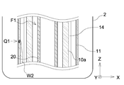
- the light source support 10 is housed in the protective tube 11 and immersed in the liquid to be treated Q1 for use, if the protective tube 11 is damaged such as a crack, the outside of the protective tube 11 is used.
- the liquid in the box enters the protective tube 11 as a leak W2.
- the leaked liquid W2 that has entered the protective tube 11 flows toward the ⁇ Z (downward in the vertical direction) side along the inner wall surface 11p of the protective tube 11.
- FIG. 6B is an enlarged view of the storage unit 12 of the light irradiation device 1 of FIG.
- the leaked liquid W2 that flows along the inner wall surface 11p of the protective tube 11 and reaches the periphery of the storage unit 12 arranged on the ⁇ Z side passes through the communication hole 12a and flows through the storage unit 12 of the storage unit 12. It flows inward.
- the leaked liquid W2 comes into contact with the detection surface 13b of the two electrodes 13a of the detection unit 13, and the two electrodes 13a are energized via the leaked liquid W2. When it occurs, the accumulation of the leaked liquid W2 is detected.
- the light irradiation device 1 of the first embodiment detects both the leak W1 caused by the cooling medium passing through the inside of the light source support 10 and the leak W2 caused by the breakage of the protective tube 11. Will be done.
- the light irradiation device 1 leaks without adhering to the LED 3 which is a light emitting element or the substrate 3b on which the wiring pattern is formed.
- the liquids (W1 and W2) can be passed through the storage unit 12 and detected by the detection unit 13.
- the detection surface 13b of the electrode 13a included in the detection unit 13 is arranged so as to face the lower side in the vertical direction, the leaked liquid (W1, W2) stored in the storage unit 12 can be detected at an early stage. can.
- the leak (W1, W2) can be detected safely and quickly.
- the power supply can be stopped or the light irradiation device 1 can be removed from the container 2.
- the outer wall surface 10q of the light source support 10 has a regular octagonal shape when viewed in the Z direction, and a substrate 3b on which the LED 3 is mounted is arranged on each side.
- the shape of the light source support 10 may be a circular shape, an elliptical shape, or another polygonal shape such as a quadrangle or a hexagon.
- the configuration of the flow path F1 shown in FIG. 3 is an example, and the flow path F1 may have any shape, and the direction in which the cooling medium flows is also the direction of the arrow shown in the figure. It is not limited to. The same applies to the configuration of the flow path F1 described in the drawings of FIGS. 3 and 3 and the direction in which the cooling medium flows.
- the light emitting element mounted on the substrate 3b is LED3, but other light emitting elements such as LD may be arranged, or phosphors may be mixed and placed. Further, each light emitting element may be a light emitting element that emits light other than ultraviolet light such as visible light or infrared light.
- the detection surface 13b of the electrode 13a faces the ⁇ Z direction (vertically downward), but in any direction such as the + Z direction (vertically upward) or the X direction or the Y direction. It may be configured to face.
- the detection unit 13 may be arranged outside the storage unit 12 or may not have the detection surface 13b.
- a plurality of flow grooves 14 are formed at equal intervals in the circumferential direction of the light source support 10, but the flow groove 14 may be one. It does not have to be formed at equal intervals in the circumferential direction of the light source support 10.
- FIG. 7A is a cross-sectional view schematically showing an embodiment of the light irradiation device 1.
- the storage portion 12 of the light irradiation device 1 has a transparency to light as compared with the first embodiment, and is composed of a tube body that covers the light source support 10.
- the storage portion 12 which is a tube body
- quartz glass or borosilicate glass which has transparency to light and can be immersed in the liquid to be treated Q1 can be adopted.
- the detection unit 13 of the second embodiment is connected to the light source support 10 by a sliding member 13c that slides in a displaceable manner in the Z direction.
- the detection surface 13b of the electrode 13a included in the detection unit 13 can be easily configured to be in contact with the bottom of the storage unit 12, and the load on the bottom of the storage unit 12 at the time of mounting can be reduced. Leakage (W1, W2) stored in the storage unit 12 can be detected earlier.
- the member connecting the detection unit 13 and the light source support 10 does not have to be a sliding member 13c as long as it can form a mechanism that can be displaced in the Z direction.
- an elastic member such as a spring or rubber may be used. It doesn't matter if there is.
- the leaked liquid W1 flows toward the ⁇ Z direction (lower side in the vertical direction) along the flow groove 14 formed on the outer wall surface 10q of the light source support 10. do.
- the leaked liquid W1 comes into contact with the detection surfaces 13b of the two electrodes 13a of the detection unit 13, and energization is generated between the two electrodes 13a, resulting in leakage.
- the accumulation of the liquid W1 is detected.
- the leaked liquid W2 flows toward the ⁇ Z direction (downward in the vertical direction) along the inner wall surface 12p of the storage portion 12.
- the leaked liquid W2 flows along the inner wall surface 12p of the storage unit 12 and is stored at the bottom of the storage unit 12.
- the leaked liquid W2 comes into contact with the detection surfaces 13b of the two electrodes 13a of the detection unit 13, and energization is generated between the two electrodes 13a. Accumulation of leaked liquid W2 is detected.
- the light irradiation device 1 of the second embodiment detects both the leak W1 caused by the cooling medium passing through the inside of the light source support 10 and the leak W2 caused by the breakage of the protective tube 11. Will be done.
- the storage unit 12 in the second embodiment is a tube body configured to cover the entire light irradiation device 1, the light irradiation device 1 is treated as a processing target without separately providing a protective tube 11 or the like. It can be used by immersing it in the liquid to be used.
- FIG. 7B is a cross-sectional view schematically showing an embodiment of the light irradiation device 1.
- the light irradiation device 1 of the second embodiment may include a light source support 10 and a protective tube 11 for accommodating the entire storage portion 12.
- the material of the protective tube 11 for example, quartz glass, borosilicate glass, or the like can be adopted as described above.
- the light irradiation device 1 can be used by being immersed in the liquid to be treated Q1 regardless of the material constituting the storage unit 12 in the second embodiment.
- FIG. 8 is a cross-sectional view schematically showing another embodiment of the light irradiation device 1.
- the light irradiation device 1 of the present invention does not have to include the protective tube 11.
- the storage portion 12 may be arranged apart from one end of the light source support 10 without covering one end of the light source support 10.
- Light irradiation device 2 Container 3: LED 3b: Substrate 10: Light source support 10a, 10b: Connecting member 10p: Inner wall surface 10q: Outer wall surface 10x: Axis 11: Protective tube 11p: Inner wall surface 12: Storage unit 12a: Communication hole 12p: Inner wall surface 13: Detection unit 13a : Electrode 13b: Detection surface 13c: Sliding member 14: Flow groove 20: Cylinder 20q: Outer wall surface 21: O-ring 22: Connecting part F1: Flow path L1: Ultraviolet light Q1: Leakage liquid
Landscapes
- Physics & Mathematics (AREA)
- General Physics & Mathematics (AREA)
- Health & Medical Sciences (AREA)
- General Health & Medical Sciences (AREA)
- Life Sciences & Earth Sciences (AREA)
- Animal Behavior & Ethology (AREA)
- Epidemiology (AREA)
- Public Health (AREA)
- Veterinary Medicine (AREA)
- Apparatus For Disinfection Or Sterilisation (AREA)
- Physical Or Chemical Processes And Apparatus (AREA)
- Led Device Packages (AREA)
- Physical Water Treatments (AREA)
Abstract
漏液が発生した場合に、安全に漏液検知が可能な光照射装置を提供する。 発光素子と、外壁面上に前記発光素子が載置される筒状の光源支持体と、前記外壁面上に前記光源支持体の軸方向に沿って形成された通流溝と、前記光源支持体の前記軸方向に係る一端部側において前記通流溝と連絡され、液体を貯留可能に形成された貯留部と、前記貯留部に貯留する液体を検知可能とする検知部とを備え、前記貯留部が設けられた前記光源支持体の前記軸方向に係る前記一端部側は、他端部側よりも鉛直下方側に配置される。
Description
本発明は、光照射装置に関し、特に発光素子によって光を照射する光照射装置に関する。
容器やタンク内における流体の殺菌処理や光化学処理用の光源として、例えば、下記特許文献1に記載されているような、複数のLEDを光源として搭載した、一方向に延伸する長尺な光照射装置が知られている。
本発明者らは、上述のような、容器やタンク内の流体の殺菌や光化学処理に用いる光照射装置について検討していたところ、以下のような課題があることを見出した。
LEDは、電力が供給されると発光すると共に発熱し、次第に温度が上昇する。しかし、LEDは、温度が上昇するにつれて発光効率が低下するため、LEDを光源とする光照射装置の多くは、冷却機構が設けられている。
例えば、上記特許文献1に記載の光照射装置のような棒状で長尺な光照射装置では、光源であるLEDが配置されている光源支持体の内側に形成された流路に冷却媒体を通流させる冷却機構が設けられている。
内側に冷却媒体が通流される光源支持体は、少なからず、冷却媒体が光源支持体の外側に漏れ出てしまうおそれがある。特に長尺な光源支持体においては、複数の部材を軸方向に連結させて形成される場合があり、この場合、軸方向に向かって一定間隔で連結部が形成されることになる。当該連結部は、運搬やメンテナンス作業のために接着剤等で完全に固定されることはなく、内部を通流する冷却媒体が外壁面に漏れ出ないように、ゴム製のOリング等を用いて漏液防止の処理が施される。
しかしながら、Oリング等によって漏液防止の処理を行った場合であっても、連結部の隙間を完全に埋めることは困難であり、光源支持体内を通流する冷却媒体の漏液を完全に防止することは難しい。また、経時的な劣化等によっても、Oリングの漏液防止の機能は低下してしまう。そして、LEDに電力が供給されている状態で冷却媒体が外壁面上に漏れ出てしまうと、LEDに電力を供給する配線のショートが発生してしまい、LED素子や配線基板、又は光照射装置自体が破損してしまうおそれがある。
本発明は、上記課題に鑑み、漏液が発生した場合に、安全に漏液検知が可能な光照射装置を提供することを目的とする。
本発明の光照射装置は、
発光素子と、
外壁面上に前記発光素子が載置され、内側に冷却媒体が通流される流路が形成された筒状の光源支持体と、
前記外壁面上に前記光源支持体の軸方向に沿って形成された通流溝と、
前記光源支持体の前記軸方向に係る一端部側において前記通流溝に連絡され、液体を貯留可能に形成された貯留部と、
前記貯留部に貯留する液体を検知可能とする検知部とを備え、
前記貯留部が設けられた前記光源支持体の前記軸方向に係る前記一端部側は、他端部側よりも鉛直下方側に配置されていることを特徴とする。
発光素子と、
外壁面上に前記発光素子が載置され、内側に冷却媒体が通流される流路が形成された筒状の光源支持体と、
前記外壁面上に前記光源支持体の軸方向に沿って形成された通流溝と、
前記光源支持体の前記軸方向に係る一端部側において前記通流溝に連絡され、液体を貯留可能に形成された貯留部と、
前記貯留部に貯留する液体を検知可能とする検知部とを備え、
前記貯留部が設けられた前記光源支持体の前記軸方向に係る前記一端部側は、他端部側よりも鉛直下方側に配置されていることを特徴とする。
発光素子は、処理対象物の殺菌処理や光化学処理を行う素子として、広範囲にわたって紫外光を出射するLEDであることが好ましいが、LD等の他の発光素子であってもよく、蛍光体等が混在して載置されていても構わない。さらに、それぞれの発光素子は、可視光や赤外光等の紫外光以外の光を出射する発光素子であっても構わない。例えば、発光素子が赤外光を出射するLEDであった場合、上記光照射装置は、処理対象物の加熱処理を行うことができる。
光源支持体の内側を通流する冷却媒体は、液体であり、例えば、水等を採用し得る。
光源支持体の一部から、内部を通流する冷却媒体が外壁面上へ漏れ出た場合、冷却媒体は、外壁面上に形成された通流溝に沿って自らの重さによって貯留部に向かうように通流する。冷却媒体は、光源支持体の外壁面上に形成された通流溝に沿って通流し、光源支持体の外壁面上に形成された発光素子へ電力を供給するための配線パターン等を避けるようにして貯留部まで導かれる。そして、冷却媒体が貯留部に到達すると、検知部は、貯留部に液体である冷却媒体が貯留していることを検知する。
したがって、上記構成とすることで、安全に光源支持体の内側を通流する冷却媒体の漏れを検知することがでる。さらに、検知部が液体を検知したことを示す信号に基づいて、すぐに発光素子への電力の供給を停止させる制御や、光照射装置の撤去動作を開始させる制御を行うシステムを構成することができる。当該システムを構成することで、光照射装置の破損してしまうことを防止する機構や、配線パターンのショート等によって火花や放電が発生し、処理対象物に引火してしまうこと等を回避する機構を設けることができる。
なお、上記構成は、貯留部を備える光源支持体の軸方向に係る一端部側が、他端部側よりも下方に配置されるが、必ずしも、光源支持体の軸が鉛直方向に配置されていなくても構わない。
上記光照射装置において、
前記検知部は、前記液体と接触することで前記液体を検知する検知面を備え、
前記検知面は、鉛直下方側に面するように配置されていても構わない。
前記検知部は、前記液体と接触することで前記液体を検知する検知面を備え、
前記検知面は、鉛直下方側に面するように配置されていても構わない。
例えば、検知部の検知面が鉛直上方に面している場合、検知部は、液体が検知面より高い位置まで貯留部に貯留しなければ、液体を検知することができない。上記構成とすることで、検知部は、水位には関係なく、検知面に接触できるだけの僅かな量であっても液体を検知することが可能となり、漏液を早期に検出することができる。
上記光照射装置は、
前記外壁面上に、前記発光素子が搭載された複数の基板を有し、
前記通流溝は、前記光源支持体の周方向において隣接する前記複数の基板の間に形成されていても構わない。
前記外壁面上に、前記発光素子が搭載された複数の基板を有し、
前記通流溝は、前記光源支持体の周方向において隣接する前記複数の基板の間に形成されていても構わない。
多くの場合、光源支持体の外壁面上には、配線パターンが構成された基板上に発光素子が載置される。また、基板は、光強度の調整や、光源支持体の形状に合わせて、光源支持体に対して複数配置される。
上記構成とすることで、液体である冷却媒体は、基板が配置されていない隙間を通流するため、基板に形成された配線パターン等に付着することなく貯留部に向かって通流する。したがって、より安全に漏液を検知することができる。
上記光照射装置において、
前記通流溝は、前記光源支持体の前記軸方向に見たときの周方向に複数形成されていても構わない。
前記通流溝は、前記光源支持体の前記軸方向に見たときの周方向に複数形成されていても構わない。
例えば、光源支持体の外壁面上に構成された通流溝が一つであった場合、光源支持体の軸方向に見たときの、軸に対して通流溝とは反対側の位置で冷却媒体の漏れが発生した場合、光源支持体の外壁面上に漏れ出た冷却媒体は、光源支持体の外壁面を周方向に向かって半周しなければ通流溝に到達することができない。したがって、通流溝に到達するまでの間に、冷却媒体が、配線パターンや発光素子に付着、又は通流溝に到達することなく貯留部に向かって外壁面上を通流してしまうことが考えられる。
そこで、光源支持体の周方向において、複数の通流溝が構成されることで、冷却媒体の漏れが発生した場合、冷却媒体は、発生場所に応じて最も近い場所に形成された通流溝を通じて、より確実に貯留部に漏液を導くことができる。したがって、漏液が基板に形成された配線パターンや発光素子に付着するおそれがさらに少なくなり、より安全に漏液を検知することができる。
複数の通流溝は、光源支持体の軸方向に見たときの周方向において、等間隔で形成されていても構わない。
上記構成とすることで、光源支持体の外壁面上に漏れ出た冷却媒体が、いずれかの通流溝に到達しやすくなり、より安全で確実に貯留部に向かって通流される。
上記光照射装置において、
前記貯留部は、前記光源支持体の前記軸方向に係る前記一端部を覆うように構成された、有内底筒状を呈する受け部からなるものであっても構わない。
前記貯留部は、前記光源支持体の前記軸方向に係る前記一端部を覆うように構成された、有内底筒状を呈する受け部からなるものであっても構わない。
上記構成とすることで、通流溝を通流してきた漏液が飛散することなく貯留部に向かって通流される。
本発明の光照射装置は、
少なくとも一部を光化学処理対象の液体に浸漬させ、
光源支持体の外壁面上に載置された発光素子から出射される光を、前記液体に対して内部から照射するように使用しても構わない。
少なくとも一部を光化学処理対象の液体に浸漬させ、
光源支持体の外壁面上に載置された発光素子から出射される光を、前記液体に対して内部から照射するように使用しても構わない。
そこで、上記光照射装置において、
前記貯留部は、光に対して透過性を有し、前記光源支持体を覆う管体からなるものであっても構わない。
前記貯留部は、光に対して透過性を有し、前記光源支持体を覆う管体からなるものであっても構わない。
上記構成とすることで、本発明の光照射装置は、管体が光源支持体を保護する機能し、光化学処理対象の液体に浸漬させて使用することができる。
さらに、上記光照射装置において、
前記光源支持体は前記検知部に対して、前記軸方向に関し、変位可能な部材によって接続されていても構わない。
前記光源支持体は前記検知部に対して、前記軸方向に関し、変位可能な部材によって接続されていても構わない。
上記構成とすることで、光源支持体を保護管の内側に挿入する際、誤って保護管の開口部とは反対側の端部に貯留部を衝突させてしまった場合に、保護管が破損しないように保護管に与える衝撃を緩和させることができる。また、検知部の検知面を貯留部の面に当接又は近接して配置させると共に、軸方向における光源支持体の配置位置が所望の位置となるように調整することができる。
また、上記光照射装置は、
光に対して透過性を有し、前記光源支持体を収容する保護管を備え、
前記貯留部は、液体が貯留する空間と、前記保護管の内側の空間とを連絡する連絡孔が形成されていても構わない。
光に対して透過性を有し、前記光源支持体を収容する保護管を備え、
前記貯留部は、液体が貯留する空間と、前記保護管の内側の空間とを連絡する連絡孔が形成されていても構わない。
上記構成とすることで、本発明の光照射装置は、光化学処理対象物が液体である場合、処理対象の液体に浸漬させて使用することができるため、処理対象の液体の内部から光を照射することができる。したがって、容器の側面や上方からの照射では光が到達しにくい容器の中央部側に滞留している処理対象の液体に対しても光を照射することができ、照射ムラが抑制され、処理時間も短縮することができる。
また、上記構成の場合は、処理対象の液体に浸漬させて使用している最中に保護管が破損して保護管内に液体が侵入した場合等に、液体が保護管の外壁に沿って保護管の底に向かって通流する。そして、保護管の底に液体が一定量貯留すると、連絡孔を介して液体が貯留部の内側に向かって通流し、貯留部に流入し、検知部によって検知される。したがって、保護管の破損によって保護管内に液体が漏れてきた場合に、液体を検知することができる。
本発明によれば、漏液が発生した場合に、安全に漏液検知が可能な光照射装置が実現される。
以下、本発明の光照射装置について、図面を参照して説明する。なお、以下の各図面は、いずれも模式的に図示されたものであり、図面上の寸法比や個数は、実際の寸法比や個数と必ずしも一致していない。
[使用態様]
図1は、光照射装置1の使用態様の一例を示す模式的な図面である。本発明の光照射装置1は、図1に示すように、棒状で長尺な形状の光源支持体10と、保護管11を備えており、光源支持体10は、外壁面上に発光素子であるLED3が複数載置されている。そして、LED3から出射された紫外光L1が処理対象である処理対象液Q1に照射されることで、容器2に溜められている処理対象液Q1が殺菌処理、又は光化学処理される。
図1は、光照射装置1の使用態様の一例を示す模式的な図面である。本発明の光照射装置1は、図1に示すように、棒状で長尺な形状の光源支持体10と、保護管11を備えており、光源支持体10は、外壁面上に発光素子であるLED3が複数載置されている。そして、LED3から出射された紫外光L1が処理対象である処理対象液Q1に照射されることで、容器2に溜められている処理対象液Q1が殺菌処理、又は光化学処理される。
本発明の光照射装置1は、図1に示すように、保護管11を設けることで、容器2内の処理対象液Q1に浸漬させることも可能とする。光照射装置1が処理対象液Q1に浸漬され、LED3から出射される紫外光L1が処理対象液Q1の内部から照射されることで、処理対象液Q1に対して有効に紫外光L1を照射でき、殺菌処理や光化学処理することができる。
なお、図1に示す使用態様は一例であり、光照射装置1の使用態様を限定するものではない。例えば、本発明の光照射装置1は、保護管11を設けず、処理対象液Q1に浸漬しない構成で使用しても構わない。そのような場合であっても、例えば、光源支持体内を流通する冷却媒体の漏液が発生した場合に、安全に漏液検知が可能となる。
以下、光照射装置1の構成の詳細につき説明する。
[第一実施形態]
図2は、光照射装置1の一実施形態の全体構成を模式的に示す断面図である。なお、以下の説明において、光源支持体10の軸10x方向をZ方向とし、Z方向に直交する面をXY平面として説明する。そして、方向を表現する際に、正負の向きを区別する場合には、「+Z方向」、「-Z方向」のように、正負の符号を付して記載され、正負の向きを区別せずに方向を表現する場合には、単に「Z方向」と記載される。
図2は、光照射装置1の一実施形態の全体構成を模式的に示す断面図である。なお、以下の説明において、光源支持体10の軸10x方向をZ方向とし、Z方向に直交する面をXY平面として説明する。そして、方向を表現する際に、正負の向きを区別する場合には、「+Z方向」、「-Z方向」のように、正負の符号を付して記載され、正負の向きを区別せずに方向を表現する場合には、単に「Z方向」と記載される。
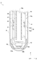
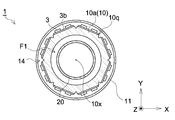
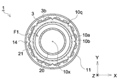
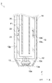
図3は、光照射装置1の一実施形態を模式的に示す断面図である。図4Aは、図3の光照射装置1の領域Aにおいて、Z方向に直交する平面で切断したときの断面図である。図4Bは、図3の光照射装置1の連結部22において、Z方向に直交する平面で切断したときの断面図である。図2~図4Bに示すように、光照射装置1は、光源支持体10と保護管11とを備え、光源支持体10は、軸方向(Z方向)に係る一端部側(-Z側)に貯留部12と、貯留部12の内側に検知部13とを備え、外壁面10q上には通流溝14が形成されている。
光源支持体10は、図3、図4A及び図4Bに示すように、筒状であって、外壁面10q上には、紫外光L1を出射する発光素子であるLED3が載置された基板3bが備えられている。基板3bは、図示はしていないが、LED3に電力を供給するための配線パターンが形成されており、給電部から供給された電力を、それぞれの基板3bを経由しながら分配するように、外壁面10q上、又は外壁面10qとは離間するように構成された導電板や配線によって接続されている。
保護管11は、例えば、図1に示すように、光照射装置1を処理対象液Q1に浸漬させて使用する場合に設けられる。保護管11は、図3、図4A及び図4Bに示すように、内側に光源支持体10が収容され、光源支持体10の外壁面10q上に載置されるLED3や基板3bに処理対象液Q1が付着し、配線のショート等が発生しないように光源支持体10を保護する。
また、保護管11は、光に対して透過性を有し、処理対象液Q1に浸漬可能な材料で形成されている。なお、本明細書における光に対して透過性を有するとは、少なくとも、処理対象物の処理に用いる波長帯の光に対して70%以上の透過率を有していればよく、必ずしも可視光に対して高い透過率を有していなくてもよい。保護管11を構成する具体的な材料は、例えば、石英ガラスや硼珪酸ガラス等を採用し得る。
貯留部12は、図3に示すように、光源支持体10のZ方向に係る一端部を覆い、有内底筒状を呈する受け部である。また、貯留部12は、保護管11の内側に貯留した液体が流入するように、液体を貯留する空間と、保護管11の内側の空間とを連絡する連絡孔12aが形成されている。
検知部13は、図3に示すように、二つの電極13aを備え、検知面13bが-Z側(鉛直下方側)に面するように配置されており、貯留部12に貯留した液体が双方の検知面13bに接触すると、液体を介して通電することで、貯留している液体を検知するように構成されている。
通流溝14は、図3、図4A及び図4Bに示すように、隣接する基板3bの間において、外壁面10q上に光源支持体10の軸10xに沿って貯留部12と連絡するように、光源支持体10の周方向に等間隔で複数形成されている。
光源支持体10の内側には、筒体20が配置されており、LED3を冷却するための冷却媒体が通流される流路F1が形成されている。流路F1は、図2及び図3に示すように、光源支持体10の軸10xと筒体20の軸とが一致するように配置され、+Z側の端部から-Z側の端部に向かって冷却媒体を通流させる筒体20の内側の往路と、-Z側の端部から+Z側の端部に向かって冷却媒体を通流させる筒体20の外壁面20qと光源支持体10の内壁面10pの間の復路を有している。なお、冷却媒体は、LED3を冷却するために、流路F1内を通流される液体であり、例えば、水等を採用し得る。
また、流路F1は、筒体20が光源支持体10の-Z側の端部から離間して配置されることで、-Z側の端部において、往路と復路とが連絡している。したがって、光源支持体10の+Z側の端部から筒体20の内側に注入された冷却媒体は、図3に示す矢印のように、筒体20の内側の往路を通流し、-Z側の端部において復路へと連絡し、筒体20の外壁面20qと光源支持体10の内壁面10pとの間の復路を通流され、+Z側から光源支持体10の外側へと排出される。
第一実施形態の光源支持体10は、複数の連結部材(10a,10b)が連結されて構成され、連結部22が形成される。第一実施形態の連結部22は、図3及び図4Bに示すように、一方の連結部材10aの凸部を、他方の連結部材10bの凹部に差し込むように連結される。
各連結部材(10a,10b)との間には、隙間を埋めるようにして、光源支持体10の内側を通流する冷却媒体が漏れ出ることを防止するためのOリング21が装着されている。なお、光源支持体10は、内側を通流する冷却媒体の漏れを抑制するために、連結部22を形成しないよう一つの部材で構成されていても構わない。
貯留部12に貯留した液体が少量でも検知できるように、検知面13bと貯留部12との距離はできる限り近くなるように配置される方がよく、当該距離は、5mm以内であることが好ましい。
第一実施形態の光源支持体10は、軸10xが鉛直方向に配置されているが、光源支持体10は、貯留部12が配置された光源支持体10の一端部が、他端部よりも鉛直下方側に配置されていれば、軸10xが鉛直方向とは非平行に配置されていてもよい。
ここで、漏液の発生と検知について図面を参照しながら説明する。
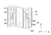
まず、連結部22において、光源支持体10の内側の流路F1を通流する冷却媒体が光源支持体10の外側に漏れ出た場合を説明する。図5Aは、図3の光照射装置1の連結部22の拡大図である。図5Aに示すように、光源支持体10が複数の連結部材(10a,10b)が連結されて構成されている場合、漏液防止のために設けられたOリング21の劣化や、欠損が発生すると、流路F1内を矢印の方向に向かって通流する冷却媒体が光源支持体10の外壁面10q上に漏液W1として漏れ出てくる。
光源支持体10の外壁面10q上に漏れ出てきた漏液W1は、光源支持体10の外壁面10q上に形成されている通流溝14に沿って、-Z方向(鉛直方向の下方)側に向かって通流する。
図5Bは、図3の光照射装置1の貯留部12の拡大図である。図5Bに示すように、通流溝14を通流し、-Z側に配置された貯留部12に達した漏液W1は、貯留部12の内側へと流れ込む。
漏液W1が貯留部12の内側に一定量貯留すると、検知部13が有する二つの電極13aの検知面13bに漏液W1が接触し、漏液W1を介して二つの電極13a間で通電が発生することで、漏液W1の貯留が検知される。
次に、領域Aにおいて、処理対象である液体が保護管11の内側に侵入した場合を説明する。図6Aは、図3の光照射装置1の領域Aの拡大図である。図6Aに示すように、光源支持体10を保護管11内に収容し、処理対象液Q1中に浸漬させて使用する場合、保護管11に亀裂等の破損が生じると、保護管11の外側にある液体が漏液W2として保護管11内に侵入する。
保護管11内に侵入した漏液W2は、保護管11の内壁面11pに沿って、-Z(鉛直方向の下方)側に向かって通流する。
図6Bは、図3の光照射装置1の貯留部12の拡大図である。図6Bに示すように、保護管11の内壁面11pに沿って通流し、-Z側に配置された貯留部12周辺に達した漏液W2は、連絡孔12aを通流して貯留部12の内側へと流れ込む。
漏液W2が貯留部12の内側に一定量貯留すると、検知部13が有する二つの電極13aの検知面13bに漏液W2が接触し、漏液W2を介して二つの電極13a間で通電が発生することで、漏液W2の貯留が検知される。
以上のようにして、第一実施形態の光照射装置1は、光源支持体10の内部を通流する冷却媒体による漏液W1と、保護管11の破損によって生じる漏液W2のいずれもが検知される。
以上の構成によれば、いずれの漏液(W1,W2)が発生した場合でも、光照射装置1は、発光素子であるLED3や、配線パターンが形成されている基板3bに付着することなく漏液(W1,W2)を貯留部12に通流させて、検知部13によって検知することができる。
また、検知部13が備える電極13aの検知面13bが鉛直方向の下方側に面するように配置されているため、貯留部12に貯留した漏液(W1,W2)を早期に検知することができる。
したがって、万が一、光照射装置1において、冷却媒体や処理対象液Q1の漏液(W1,W2)が発生した場合に、安全、かつ迅速に漏液(W1,W2)を検知することができ、光照射装置1の破損や、不具合が発生した場合に、電力供給の停止や、光照射装置1を容器2から撤去することができる。
また、図4A及び図4Bに示すように、光源支持体10の外壁面10qは、Z方向に見たときに、正八角形を呈し、各辺にLED3が載置された基板3bが配置されているが、光源支持体10の形状は、円形や楕円形、又は四角形や六角形等の他の多角形であっても構わない。
また、図3、に図示されている流路F1の構成は、一例であって、どのような形状の流路F1であってもよく、冷却媒体が通流する方向も図示された矢印の方向に限定されるものではない。なお、図3以降の図面において記載されている流路F1の構成や、冷却媒体の通流する方向に関しても同様である。
基板3bに搭載された発光素子は、LED3としたが、LD等の他の発光素子を配置してもよく、蛍光体が混在して載置されていても構わない。さらに、それぞれの発光素子は、可視光や赤外光等の紫外光以外の光を出射する発光素子であっても構わない。
第一実施形態の検知部13は、電極13aの検知面13bが、-Z方向(鉛直下方)に面しているが、+Z方向(鉛直上方)、又はX方向やY方向等、いずれの方向に面するように構成されていても構わない。
また、貯留部12に貯留した液体を検知する方法としては、例えば、光の屈折を利用した方法等も採用し得る。検知の方法によっては、検知部13は、貯留部12の外側に配置されていてもよく、検知面13bを有していなくても構わない。
第一実施形態の通流溝14は、光源支持体10の周方向において、等間隔に複数の通流溝14が形成されているが、通流溝14は、一つであってもよく、光源支持体10の周方向において等間隔に形成されていなくても構わない。
[第二実施形態]
本発明の光照射装置1の第二実施形態の構成につき、第一実施形態とは異なる箇所を中心に説明する。
本発明の光照射装置1の第二実施形態の構成につき、第一実施形態とは異なる箇所を中心に説明する。
図7Aは、光照射装置1の一実施形態を模式的に示す断面図である。図7Aに示すように、光照射装置1の貯留部12は、第一実施形態と比較して、光に対して透過性を有し、光源支持体10を覆う管体で構成されている。
管体である貯留部12を構成する具体的な材料は、光に対して透過性を有し、処理対象液Q1に浸漬可能な、例えば、石英ガラスや硼珪酸ガラス等を採用し得る。
また、第二実施形態の検知部13は、Z方向に変位可能に摺動する摺動部材13cで光源支持体10と接続されている。これにより、検知部13が備える電極13aの検知面13bが、貯留部12の底と当接するように構成しやすくなり、取り付けの際に貯留部12の底への負荷も軽減することができ、より早く貯留部12に貯留した漏液(W1,W2)を検知することができる。
なお、検知部13と光源支持体10とを接続する部材は、Z方向に変位可能な機構を構成できる部材であれば摺動部材13cでなくてもよく、例えば、バネやゴムといった弾性部材であっても構わない。
第一実施形態と同様に、漏液W1は、光源支持体10の外壁面10q上に形成されている通流溝14に沿って、-Z方向(鉛直方向の下方)側に向かって通流する。
通流溝14を通流し、下方に配置された貯留部12に達した漏液W1は、貯留部12の内側へと流れ込む。漏液W1が貯留部12の内側に一定量貯留すると、検知部13が有する二つの電極13aの検知面13bに漏液W1が接触し、二つの電極13a間で通電が発生することで、漏液W1の貯留が検知される。
第二実施形態の場合、漏液W2は、貯留部12の内壁面12pに沿って、-Z方向(鉛直方向の下方)側に向かって通流する。
漏液W2は、貯留部12の内壁面12pに沿って通流し、貯留部12の底に貯留する。貯留部12の底に一定量の漏液W2が貯留すると、検知部13が有する二つの電極13aの検知面13bに漏液W2が接触し、二つの電極13a間で通電が発生することで、漏液W2の貯留が検知される。
以上のようにして、第二実施形態の光照射装置1は、光源支持体10の内部を通流する冷却媒体による漏液W1と、保護管11の破損によって生じる漏液W2のいずれもが検知される。
また、第二実施形態における貯留部12は、光照射装置1全体を覆うように構成された管体であるため、別途、保護管11等を設けることなく、光照射装置1は、処理対象とする液に浸漬させて使用することができる。
図7Bは、光照射装置1の一実施形態を模式的に示す断面図である。第二実施形態の光照射装置1は、図7Bに示すように、光源支持体10と貯留部12全体を収容する保護管11を備えていても構わない。なお、保護管11の材料は、上述したように、例えば、石英ガラスや硼珪酸ガラス等を採用し得る。
上記構成とすることで、保護管11を有することで、第二実施形態における貯留部12を構成する材料によらず、光照射装置1を処理対象液Q1に浸漬させて使用することができる。
[別実施形態]
以下、別実施形態につき説明する。
以下、別実施形態につき説明する。
〈1〉 図8は、光照射装置1の別実施形態を模式的に示す断面図である。処理対象物に対して外側から光を照射する場合等では、図8に示すように、本発明の光照射装置1は、保護管11を備えていなくても構わない。また、貯留部12が光源支持体10の一端部を覆うことなく、光源支持体10の一端部から離間して配置されていても構わない。
〈2〉 上述した光照射装置1が備える構成は、あくまで一例であり、本発明は、図示された各構成に限定されない。
1 : 光照射装置
2 : 容器
3 : LED
3b : 基板
10 : 光源支持体
10a,10b : 連結部材
10p : 内壁面
10q : 外壁面
10x : 軸
11 : 保護管
11p : 内壁面
12 : 貯留部
12a : 連絡孔
12p : 内壁面
13 : 検知部
13a : 電極
13b : 検知面
13c : 摺動部材
14 : 通流溝
20 : 筒体
20q : 外壁面
21 : Oリング
22 : 連結部
F1 : 流路
L1 : 紫外光
Q1 : 処理対象液
W1,W2 : 漏液
2 : 容器
3 : LED
3b : 基板
10 : 光源支持体
10a,10b : 連結部材
10p : 内壁面
10q : 外壁面
10x : 軸
11 : 保護管
11p : 内壁面
12 : 貯留部
12a : 連絡孔
12p : 内壁面
13 : 検知部
13a : 電極
13b : 検知面
13c : 摺動部材
14 : 通流溝
20 : 筒体
20q : 外壁面
21 : Oリング
22 : 連結部
F1 : 流路
L1 : 紫外光
Q1 : 処理対象液
W1,W2 : 漏液
Claims (8)
- 発光素子と、
外壁面上に前記発光素子が載置され、内側に冷却媒体が通流される流路が形成された筒状の光源支持体と、
前記外壁面上に前記光源支持体の軸方向に沿って形成された通流溝と、
前記光源支持体の前記軸方向に係る一端部側において前記通流溝に連絡され、液体を貯留可能に形成された貯留部と、
前記貯留部に貯留する液体を検知可能とする検知部とを備え、
前記貯留部が設けられた前記光源支持体の前記軸方向に係る前記一端部側は、他端部側よりも鉛直下方側に配置されることを特徴とする光照射装置。 - 前記検知部は、前記液体と接触することで前記液体を検知する検知面を備え、
前記検知面は、鉛直下方側に面するように配置されていることを特徴とする請求項1に記載の光照射装置。 - 前記外壁面上に、前記発光素子が搭載された複数の基板を有し、
前記通流溝は、前記光源支持体の周方向において隣接する前記複数の基板の間に形成されていることを特徴とする請求項1又は2に記載の光照射装置。 - 前記通流溝は、前記光源支持体の前記軸方向に見たときの周方向に複数形成されていることを特徴とする請求項1~3のいずれか一項に記載の光照射装置。
- 前記貯留部は、前記光源支持体の前記軸方向に係る前記一端部を覆うように構成された、有内底筒状を呈する受け部からなることを特徴とする請求項1~4のいずれか一項に記載の光照射装置。
- 前記貯留部は、光に対して透過性を有し、前記光源支持体と前記検知部とを覆う管体からなることを特徴とする請求項1~4のいずれか一項に記載の光照射装置。
- 前記光源支持体は、前記検知部に対して、前記軸方向に変位可能な部材で接続されていることを特徴とする請求項6に記載の光照射装置。
- 光に対して透過性を有し、前記光源支持体と前記貯留部とを収容する保護管を備え、
前記貯留部は、液体が貯留する空間と、前記保護管の内側の空間とを連絡する連絡孔が形成されていることを特徴とする請求項1~7のいずれか一項に記載の光照射装置。
Priority Applications (1)
| Application Number | Priority Date | Filing Date | Title |
|---|---|---|---|
| US17/794,211 US12385800B2 (en) | 2020-01-24 | 2020-12-03 | Light irradiation device |
Applications Claiming Priority (2)
| Application Number | Priority Date | Filing Date | Title |
|---|---|---|---|
| JP2020009735A JP7331713B2 (ja) | 2020-01-24 | 2020-01-24 | 光照射装置 |
| JP2020-009735 | 2020-01-24 |
Publications (1)
| Publication Number | Publication Date |
|---|---|
| WO2021149367A1 true WO2021149367A1 (ja) | 2021-07-29 |
Family
ID=76992221
Family Applications (1)
| Application Number | Title | Priority Date | Filing Date |
|---|---|---|---|
| PCT/JP2020/045055 Ceased WO2021149367A1 (ja) | 2020-01-24 | 2020-12-03 | 光照射装置 |
Country Status (3)
| Country | Link |
|---|---|
| US (1) | US12385800B2 (ja) |
| JP (1) | JP7331713B2 (ja) |
| WO (1) | WO2021149367A1 (ja) |
Cited By (1)
| Publication number | Priority date | Publication date | Assignee | Title |
|---|---|---|---|---|
| CN117968989A (zh) * | 2024-04-02 | 2024-05-03 | 武汉武热研热处理科技有限公司 | 一种离子氮化炉故障检测装置 |
Families Citing this family (1)
| Publication number | Priority date | Publication date | Assignee | Title |
|---|---|---|---|---|
| CN120769724A (zh) * | 2023-03-14 | 2025-10-10 | 索高视觉有限公司 | 一种荧光成像设备的成像头的冷却系统 |
Citations (2)
| Publication number | Priority date | Publication date | Assignee | Title |
|---|---|---|---|---|
| JP2013200944A (ja) * | 2012-03-23 | 2013-10-03 | Harison Toshiba Lighting Corp | 光源装置 |
| JP2015216017A (ja) * | 2014-05-09 | 2015-12-03 | 東芝ライテック株式会社 | 照明装置 |
Family Cites Families (1)
| Publication number | Priority date | Publication date | Assignee | Title |
|---|---|---|---|---|
| JP2017143971A (ja) | 2016-02-16 | 2017-08-24 | 三菱重工メカトロシステムズ株式会社 | 容器の殺菌装置 |
-
2020
- 2020-01-24 JP JP2020009735A patent/JP7331713B2/ja active Active
- 2020-12-03 US US17/794,211 patent/US12385800B2/en active Active
- 2020-12-03 WO PCT/JP2020/045055 patent/WO2021149367A1/ja not_active Ceased
Patent Citations (2)
| Publication number | Priority date | Publication date | Assignee | Title |
|---|---|---|---|---|
| JP2013200944A (ja) * | 2012-03-23 | 2013-10-03 | Harison Toshiba Lighting Corp | 光源装置 |
| JP2015216017A (ja) * | 2014-05-09 | 2015-12-03 | 東芝ライテック株式会社 | 照明装置 |
Cited By (2)
| Publication number | Priority date | Publication date | Assignee | Title |
|---|---|---|---|---|
| CN117968989A (zh) * | 2024-04-02 | 2024-05-03 | 武汉武热研热处理科技有限公司 | 一种离子氮化炉故障检测装置 |
| CN117968989B (zh) * | 2024-04-02 | 2024-06-07 | 武汉武热研热处理科技有限公司 | 一种离子氮化炉故障检测装置 |
Also Published As
| Publication number | Publication date |
|---|---|
| JP7331713B2 (ja) | 2023-08-23 |
| JP2021118242A (ja) | 2021-08-10 |
| US20230052579A1 (en) | 2023-02-16 |
| US12385800B2 (en) | 2025-08-12 |
Similar Documents
| Publication | Publication Date | Title |
|---|---|---|
| JP6506741B2 (ja) | 殺生物性浄化デバイス | |
| US20160137528A1 (en) | Device for treating a medium using uv radiation | |
| JP6374403B2 (ja) | 発光ダイオードから放射された光による液体消毒方法及び装置 | |
| JP6710139B2 (ja) | 殺菌装置 | |
| JP7331713B2 (ja) | 光照射装置 | |
| JP6615893B2 (ja) | 紫外線発光ダイオードを用いた水処理用の紫外線照射装置、及び紫外線照射を利用した水処理方法 | |
| US20210276887A1 (en) | Ultraviolet irradiation device and method | |
| KR102667722B1 (ko) | 광 조사 장치 | |
| US11952293B2 (en) | Apparatus for disinfecting a fluid | |
| JP2013220126A (ja) | 紫外線殺菌装置 | |
| JP2021041382A (ja) | 流体殺菌装置 | |
| WO2016051664A1 (ja) | 固体レーザ装置 | |
| JP6312812B2 (ja) | 光学流体処理装置 | |
| JP5408499B2 (ja) | 光照射装置 | |
| KR20160011517A (ko) | 수처리 장치 | |
| KR102103976B1 (ko) | 자외선 살균 장치 | |
| KR20140084965A (ko) | 살균된 중화제 공급이 가능한 중화제 공급장치 및 이를 이용하는 밸러스트수 처리시스템 | |
| JP2019147114A (ja) | 流体殺菌装置 | |
| KR100444766B1 (ko) | 생수및물저장통내의살균장치 | |
| KR20180130822A (ko) | 살균 장치 | |
| KR102706693B1 (ko) | 살균 장치 | |
| KR20160056074A (ko) | 수처리 장치 | |
| JP2023047421A (ja) | 流体殺菌装置 | |
| JP2025180596A (ja) | 流体殺菌装置 | |
| JP2010027357A (ja) | 紫外線照射用光源および光照射器 |
Legal Events
| Date | Code | Title | Description |
|---|---|---|---|
| 121 | Ep: the epo has been informed by wipo that ep was designated in this application |
Ref document number: 20915717 Country of ref document: EP Kind code of ref document: A1 |
|
| NENP | Non-entry into the national phase |
Ref country code: DE |
|
| 122 | Ep: pct application non-entry in european phase |
Ref document number: 20915717 Country of ref document: EP Kind code of ref document: A1 |
|
| WWG | Wipo information: grant in national office |
Ref document number: 17794211 Country of ref document: US |