WO2021149142A1 - 空気調和機の室外機 - Google Patents
空気調和機の室外機 Download PDFInfo
- Publication number
- WO2021149142A1 WO2021149142A1 PCT/JP2020/001897 JP2020001897W WO2021149142A1 WO 2021149142 A1 WO2021149142 A1 WO 2021149142A1 JP 2020001897 W JP2020001897 W JP 2020001897W WO 2021149142 A1 WO2021149142 A1 WO 2021149142A1
- Authority
- WO
- WIPO (PCT)
- Prior art keywords
- hole
- fixed frame
- sheet metal
- protective sheet
- portion side
- Prior art date
- Legal status (The legal status is an assumption and is not a legal conclusion. Google has not performed a legal analysis and makes no representation as to the accuracy of the status listed.)
- Ceased
Links
Images




Classifications
-
- F—MECHANICAL ENGINEERING; LIGHTING; HEATING; WEAPONS; BLASTING
- F24—HEATING; RANGES; VENTILATING
- F24F—AIR-CONDITIONING; AIR-HUMIDIFICATION; VENTILATION; USE OF AIR CURRENTS FOR SCREENING
- F24F1/00—Room units for air-conditioning, e.g. separate or self-contained units or units receiving primary air from a central station
- F24F1/06—Separate outdoor units, e.g. outdoor unit to be linked to a separate room comprising a compressor and a heat exchanger
- F24F1/20—Electric components for separate outdoor units
- F24F1/24—Cooling of electric components
Definitions
- This disclosure relates to an outdoor unit of an air conditioner equipped with an electrical component unit having a ventilation path.
- Patent Document 1 discloses an outdoor unit of an air conditioner provided with a cooling device capable of efficiently cooling a heat generating element without enlarging the radiator.
- the outdoor unit of the air conditioner disclosed in Patent Document 1 is provided with a ventilation path for the purpose of exhausting heat generated from a compressor during operation, an element mounted on a control board, or the like. It is designed so that the wind flows from the machine room to the blower room.
- the present disclosure is for solving the above-mentioned problems, and provides an outdoor unit of an air conditioner capable of preventing water from entering the electrical component unit while maintaining the amount of ventilation in the electrical component unit.
- the purpose is for solving the above-mentioned problems, and provides an outdoor unit of an air conditioner capable of preventing water from entering the electrical component unit while maintaining the amount of ventilation in the electrical component unit.
- the outdoor unit of the air conditioner according to the present disclosure includes a blower room, a machine room separated from the blower room, a first portion provided in the blower room, and a second part provided in the machine room.
- the electrical component unit includes a product unit, and the electrical component unit includes a fixed frame in which an internal space is divided into the first portion side and the second portion side by a partition wall, and a control board fixed to the fixed frame.
- a heat radiating member assembled on the lower surface of the control board and fitted into a fixing hole formed by the fixing frame on the first portion side and the partition wall, in a direction intersecting the wall surface of the fixing frame.
- a protective sheet metal having an extending surface and protecting the heat radiating member is provided, and the protective sheet metal is on the outer peripheral side of the fixed frame on the first portion side so as to surround the fixed frame on the first portion side.
- a first through hole is formed in the wall surface of the fixed frame on the first portion side, and a second through hole is formed in the surface of the protective sheet metal. The second through hole is located below the first through hole and communicates with the first through hole.
- the wall surface of the fixed frame in which the first through hole of the electrical component unit is formed and the surface of the protective sheet metal in which the second through hole of the electrical component unit is formed are formed. , Extend in the direction of crossing each other. Therefore, it is possible to prevent water from entering the electrical component unit while maintaining the amount of ventilation in the electrical component unit.
- FIG. 9 is a bottom view showing a substrate fixing frame according to the present embodiment in FIG. 9. It is sectional drawing of the electrical component unit in this embodiment.
- the X direction indicates the left-right direction of the outdoor unit, and the arrow indicates the right-to-left direction.
- the Y direction indicates the front-rear direction of the outdoor unit, and the arrow indicates the front-to-back direction.
- the Z direction indicates the vertical direction of the outdoor unit, and the arrow indicates the upward direction from the bottom.
- FIG. 1 is a perspective view showing the appearance of the outdoor unit 100 of the air conditioner according to the present embodiment.
- the outdoor unit 100 of the air conditioner according to the present embodiment has a front plate 1, a side plate 2, a top plate 3, and a protective cover 4.
- FIG. 2 is a perspective view showing the inside of the outdoor unit 100 of the air conditioner according to the present embodiment.
- the outdoor unit 100 of the air conditioner according to the present embodiment is internally partitioned into a blower room 5 and a machine room 6 by a partition plate 7.
- An electrical component unit 16 is fixed to the upper end of the partition plate 7.
- Each component housed inside the outdoor unit 100 is held on a bottom plate 9 having legs 8.
- the protective cover 4 is attached to the side plate 2.
- a heat exchanger 10 is arranged in the blower room 5.
- a motor 12 to which a propeller fan 11 is attached is held and arranged on a motor mount 13 in front of the heat exchanger 10.
- the propeller fan 11 operates, the air that has passed through the heat exchanger 10 flows into the outdoor unit 100, passes through the propeller fan 11, and flows out in front of the outdoor unit 100.
- the machine room 6 is provided with a compressor 14 and a refrigerant pipe 15.
- the refrigerant sent from the indoor unit (not shown) is compressed by the compressor 14, passes through the refrigerant pipe 15, and is sent to the heat exchanger 10.
- the refrigerant in the heat exchanger 10 is cooled by air, and the air that has passed through the heat exchanger 10 is overheated by exchanging heat with the refrigerant.
- the electrical component unit 16 is composed of a first portion 16a arranged on the blower room 5 side and a second portion 16b arranged on the machine room 6 side.
- the electrical component unit 16 supplies electric power to each component.
- a terminal block 18 connected to the outdoor unit 100 and the indoor unit (not shown) is screw-fixed to the end of the electrical component unit 16 on the second portion 16b side.
- FIG. 3 is a top perspective view showing the electrical component unit 16 according to the present embodiment.
- FIG. 4 is a bottom perspective view showing the electrical component unit 16 according to the present embodiment.
- FIG. 5 is an exploded perspective view of the electrical component unit 16 according to the present embodiment as viewed from the lower surface.
- the electrical component unit 16 includes a substrate fixing frame 20 and a heat radiating member protective sheet metal 23. Further, a substrate protection sheet metal 21 is attached to the electrical component unit 16.
- the substrate fixing frame 20 has a rectangular frame shape in a plan view.
- the board fixing frame 20 is a frame in which a control board 19 on which electronic components such as heat generating elements are mounted is fitted and fixed.
- the substrate fixing frame 20 is an example of the fixing frame.
- a heat radiating member 22 is assembled on the lower surface of the control board 19 fixed to the board fixing frame 20.
- the heat radiating member 22 is provided to assist the exhaust heat from the electronic components mounted on the control board 19.
- the heat radiating member 22 has a plurality of fins made of a material having high thermal conductivity such as aluminum.
- the outer periphery of the heat radiating member 22 is surrounded by a rainwater intrusion prevention wall 25 extending from the substrate fixing frame 20.
- the substrate protection sheet metal 21 is a rectangular sheet metal in a plan view, and is attached to the upper surface side of the substrate fixing frame 20.
- the substrate protection sheet metal 21 covers the lower surface of the control substrate 19, that is, the back surface of the surface of the control substrate 19 to which the heat dissipation member 22 is assembled, and protects the control substrate 19.
- the heat radiating member protective sheet metal 23 is attached to the board fixing frame 20 from the surface side on which the heat radiating member 22 of the control board 19 is assembled. That is, the heat radiating member protective sheet metal 23 is attached to the substrate fixing frame 20 from the lower surface side of the control substrate 19. The heat radiating member protective sheet metal 23 is attached to the outer peripheral side of the rainwater intrusion prevention wall 25. The heat radiating member protection sheet metal 23 is provided to protect the heat radiating member 22.
- the heat radiating member protective sheet metal 23 is an example of the protective sheet metal.
- the first portion 16a is arranged on the blower chamber 5, so that the heat radiating member 22 is exposed in the blower chamber 5 and is cooled by the air flow generated by the propeller fan 11. Further, when the propeller fan 11 operates, an air flow is generated inside the electrical component unit 16, a ventilation path described later is formed, and the electronic components mounted on the control board 19 are cooled.
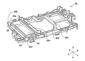
- FIG. 6 is a top perspective view showing the substrate fixing frame 20 according to the present embodiment.
- FIG. 7 is a bottom perspective view showing the substrate fixing frame 20 according to the present embodiment.
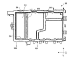
- FIG. 8 is a top view showing the substrate fixing frame 20 according to the present embodiment.
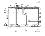
- FIG. 9 is a bottom view showing the substrate fixing frame 20 according to the present embodiment.
- the substrate fixing frame 20 is composed of a first substrate fixing frame 201 and a second substrate fixing frame 202.
- the space formed inside the substrate fixing frame 20 is partitioned by a partition wall 204, which is a wall extending in the front-rear direction.
- the first substrate fixing frame 201 constitutes one of the left and right sides of the substrate fixing frame 20
- the second substrate fixing frame 202 constitutes the other.
- the first substrate fixing frame 201 belongs to the first portion 16a of the electrical component unit 16
- the second substrate fixing frame 202 belongs to the second portion 16b of the electrical component unit 16.
- the second substrate fixing frame 202 is divided into a plurality of regions by a support member 203 for supporting the control substrate 19.
- the support member 203 is composed of a plate-shaped or rod-shaped member that connects the sides of the second substrate fixing frame 202.
- the control board 19 fixed to the board fixing frame 20 is supported by the partition wall 204 and the support member 203.
- the configuration of the support member 203 is not limited, and it is sufficient that the control board 19 can be supported.
- the first substrate fixing frame 201 is provided with a rainwater intrusion prevention wall 25 and a first through hole 26.
- the hole surrounded by the first substrate fixing frame 201 and the partition wall 204 is referred to as a heat radiating member fixing hole 24.
- the heat radiating member fixing hole 24 has a rectangular shape in a plan view.
- the heat radiating member 22 assembled to the control board 19 is fixed to the heat radiating member fixing hole 24.
- the heat radiating member fixing hole 24 is an example of the fixing hole.
- the rainwater intrusion prevention wall 25 is erected from the edges of the first substrate fixing frame 201 and the partition wall 204 forming the heat radiating member fixing hole 24.
- the heat radiating member 22 fixed to the heat radiating member fixing hole 24 is fitted into the rainwater intrusion prevention wall 25.
- the rainwater intrusion prevention wall 25 is in close contact with the heat radiating member 22 in a state where the heat radiating member 22 is inserted into the heat radiating member fixing hole 24. As a result, water intrusion from between the rainwater intrusion prevention wall 25 and the heat radiating member 22 is prevented.
- the dimensions of the rainwater intrusion prevention wall 25 are not limited.
- the rainwater intrusion prevention wall 25 may be erected from at least the edge of the first substrate fixing frame 201.
- the edges of the first substrate fixing frame 201 and the partition wall 204 may have a shape extending inward in the direction intersecting the first substrate fixing frame 201 and the partition wall 204.
- the edges of the first substrate fixing frame 201 and the partition wall 204 are formed with a step at the boundary between the first substrate fixing frame 201 and the partition wall 204 and the rainwater intrusion prevention wall 25, so that the heat radiating member protective sheet metal 23 can be easily attached. become.
- the first substrate fixing frame 201 has a double wall structure composed of a first wall surface 20a and a second wall surface 20b facing each other in a plan view.
- a groove is formed between the first wall surface 20a and the second wall surface 20b.
- a first through hole 26 is formed in the first wall surface 20a inside the second wall surface 20b.
- the first wall surface 20a is a wall extending from the edge of the heat radiating member fixing hole 24.
- the second wall surface 20b extends parallel to the first wall surface 20a at a position separated outward from the first wall surface 20a.
- the first wall surface 20a is an example of a wall surface.
- the first wall surface 20a of the present embodiment is composed of two walls adjacent to each other with the corner portion interposed therebetween, and constitutes the corner portion of the first substrate fixing frame 201.
- the second wall surface 20b may be connected at the corners.
- the first through hole 26 is a hole through which the air circulated through the electrical component unit 16 circulates.
- the first through hole 26 is formed in a shape in which a part of the first wall surface 20a of the first substrate fixing frame 201 is cut out in a rectangular shape.
- the shape of the first through hole 26 is not limited to the shape shown in FIGS. 6 to 9, and may be any shape that penetrates the first wall surface 20a of the first substrate fixing frame 201.
- At least one first through hole 26 may be formed on the first wall surface 20a.
- the first through hole 26 is formed in a pair of first wall surfaces 20a facing each other of the first substrate fixing frame 201. By doing so, the amount of ventilation in the substrate fixing frame 20 can be further improved.
- the second substrate fixing frame 202 may also have a double structure. Further, in the present embodiment, an example in which a double wall structure composed of the first wall surface 20a and the second wall surface 20b is provided below the heat radiating member fixing hole 24 is shown, but above the heat radiating member fixing hole 24. , A similar double wall structure may be provided.
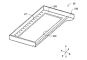
- FIG. 10 is a perspective view showing a heat radiating member protective sheet metal 23 according to the present embodiment.
- FIG. 11 is a top view showing the heat radiating member protective sheet metal 23 according to the present embodiment.
- the heat radiating member protective sheet metal 23 is a rectangular sheet metal having a main surface 231.
- a plurality of second through holes 27 and openings 232 are formed on the main surface 231 of the heat radiating member protective sheet metal 23.
- the opening 232 of the heat radiating member protective sheet metal 23 is formed in the center of the main surface 231 of the heat radiating member protective sheet metal 23.
- the heat radiating member 22 is inserted into the opening 232 of the heat radiating member protective sheet metal 23.
- the heat radiating member protective sheet metal 23 surrounds the outer peripheral side of the rainwater intrusion prevention wall 25 erected from the edge of the first substrate fixing frame 201 forming the heat radiating member fixing hole 24 and the partition wall 204.
- the heat radiating member protective sheet metal 23 is attached to the outer peripheral side of the first substrate fixing frame 201 and the partition wall 204.
- the main surface 231 of the heat radiating member protective sheet metal 23 is arranged in the electrical component unit 16 so as to extend in a direction intersecting the rainwater intrusion prevention wall 25.
- the heat radiating member protective sheet metal 23 is between the propeller fan 11 and the first wall surface 20a of the first substrate fixing frame 201 in which the first through hole 26 is formed, in a state where the electrical component unit 16 is attached to the outdoor unit 100. It is arranged so as to intervene in.
- the heat radiating member protection sheet metal 23 protects the heat radiating member 22 and prevents water from entering the electrical component unit 16.
- a plurality of second through holes 27 are formed along the longitudinal direction of the main surface 231 of the heat radiating member protective sheet metal 23.
- the second through hole 27 is a hole through which air passes through the first through hole 26.
- the main surface 231 of the heat radiating member protective sheet metal 23 in which the second through hole 27 is formed is formed with the first through hole 26 when the electrical component unit 16 is viewed from the side. It extends in a direction intersecting the first wall surface 20a of the first substrate fixing frame 201. Further, the second through hole 27 is located below the first through hole 26.
- the longitudinal direction of the main surface 231 of the heat radiating member protective sheet metal 23 in which the second through hole 27 is formed faces the first substrate fixing frame 201 in which the first through hole 26 is formed in a plan view of the electrical component unit 16. It is arranged so as to extend in a direction intersecting the pair of first wall surfaces 20a.
- a flange portion 233 extending in a direction intersecting the main surface 231 is formed on one outer peripheral edge in the longitudinal direction and both outer peripheral edges in the lateral direction. ..
- the flange portion 233 is arranged along the second wall surface 20b of the first substrate fixing frame 201.
- the flange portion 233 faces the first wall surface 20a of the first substrate fixing frame 201.
- the flange portion 233 in the longitudinal direction of the heat radiating member protective sheet metal 23 faces the first wall surface 20a extending in the longitudinal direction of the first substrate fixing frame 201.
- the flange portion 233 in the longitudinal direction of the heat radiating member protective sheet metal 23 is continuous with the main surface 231 in which the second through hole 27 is formed.
- the heat radiating member protective sheet metal 23 When the heat radiating member protective sheet metal 23 is attached to the first substrate fixing frame 201, a space is formed between the heat radiating member protective sheet metal 23 and the first wall surface 20a of the first substrate fixing frame 201. Then, the first substrate fixing frame 201 and the blower chamber 5 communicate with each other through the second through hole 27 of the heat radiating member protective sheet metal 23.
- the second through hole 27 is formed in the longitudinal direction of the heat radiating member protective sheet metal 23
- the arrangement of the second through hole 27 is not limited to this example.
- the surface of the heat-dissipating member protective sheet metal 23 in which the second through hole 27 is formed may intersect with the first wall surface 20a in which the first through hole 26 is formed.
- FIG. 12 is a bottom view showing the substrate fixing frame 20 according to the present embodiment in FIG.
- FIG. 13 is a cross-sectional perspective view of the electrical component unit 16 according to the present embodiment.
- FIG. 13 shows a cross section of the substrate fixing frame 20 shown in FIG. 12 along the position corresponding to the line AA.
- the air flow is conceptually indicated by arrows.
- the first through hole 26 of the first substrate fixing frame 201 communicates with the inside of the electrical component unit 16, and the second through hole 27 of the heat radiating member protective sheet metal 23 communicates with the blower chamber 5. do.
- the electrical component unit 16 and the blower chamber 5 communicate with each other via a ventilation path 28 formed between the first through hole 26 and the second through hole 27.
- the electrical component unit 16 When the propeller fan 11 is driven, the electrical component unit 16 becomes a negative pressure, and an air flow is generated in the ventilation path 28 communicating the first through hole 26 and the second through hole 27. In the electrical component unit 16, an air flow is generated from the second portion 16b to the first portion 16a. The air flowing in the electrical component unit 16 cools the electronic components mounted on the control board 19, becomes heated, and moves to the first portion 16a of the electrical component unit 16.
- the air flowing through the first portion 16a reaches the first through hole 26 formed in the first wall surface 20a of the first substrate fixing frame 201. Then, air flows from the first through hole 26 along the ventilation path 28 formed in the space between the first wall surface 20a of the first substrate fixing frame 201 and the flange portion 233 of the heat radiating member protective sheet metal 23.
- the ventilation path 28 bent.
- the air passing through the ventilation path 28 changes the direction of flow at this corner.
- the air bent at the corner changes direction toward the main surface 231 of the heat radiating member protective sheet metal 23 extending in the direction intersecting the first wall surface 20a on the downstream side of the corner. That is, the air changes its flow direction downward along the ventilation path 28.
- the air is discharged to the blower chamber 5 from the second through hole 27 formed in the main surface 231 of the heat radiating member protective sheet metal 23.
- the water wound up by the propeller fan 11 is scattered on the heat radiating member protective sheet metal 23 interposed between the propeller fan 11 and the first wall surface 20a of the first substrate fixing frame 201.
- Water may pass through the second through hole 27 communicating with the blower chamber 5, but the first through hole 26 communicating with the second through hole 27 is provided with the second through hole 27. It is provided on the surface that intersects the surface. That is, the main surface 231 of the heat radiating member protective sheet metal 23 in which the second through hole 27 is formed intersects with the first wall surface 20a of the first substrate fixing frame 201 in which the first through hole 26 is formed.
- first wall surface 20a in the lateral direction in which the first through hole 26 is formed intersects with the first wall surface 20a in the longitudinal direction in which the second through hole 27 is formed. Therefore, the space between the first substrate fixing frame 201 and the heat radiating member protective sheet metal 23 cuts off the path of water that has passed through the second through hole 27.
- the outdoor unit 100 of the air conditioner according to the present embodiment described above has the first wall surface 20a of the first substrate fixing frame 201 in which the first through hole 26 of the electrical component unit 16 is formed, and the second through hole. It extends in the direction in which the main surface 231 of the heat radiating member protective sheet metal 23 on which the 27 is formed intersects. Further, the first through hole 26 and the second through hole 27 communicate with each other, and a ventilation path 28 is formed between the first through hole 26 and the second through hole 27. Therefore, the air absorbed from the control board 19 is discharged from the electrical component unit 16 to the blower chamber 5 through the first through hole 26 and the second through hole 27.
- the water scattered from the blower chamber 5 can flow in from the second through hole 27, but the moving direction of the water through the second through hole 27 does not face the direction of the surface of the first through hole 26, so that the first The through hole 26 cannot be reached.
- the ventilation amount of the electrical component unit 16 can be maintained, and the infiltration of moisture from the blower chamber 5 into the electrical component unit 16 can be prevented.
- the ventilation amount can be improved.
- the first wall surface 20a closest to the second through hole 27 is adjacent to the first wall surface 20a in the lateral direction in which the first through hole 26 is formed so as to sandwich a corner portion. Therefore, the ventilation path 28 from the first through hole 26 to the second through hole 27 is changed from the direction along the first substrate fixing frame 201 to the direction in which the corner is bent, and further, the main of the heat dissipation member protective sheet metal 23. The direction is changed to the surface 231. That is, the ventilation path 28 is formed three-dimensionally. Since the movement of water is two-dimensional, it is possible to prevent the water from reaching the control board 19 even if it flows in from the second through hole 27.
- the ventilation path 28 is formed by the first substrate fixing frame 201 and the heat radiating member protective sheet metal 23, and the air absorbed from the substrate can flow.
Landscapes
- Engineering & Computer Science (AREA)
- Chemical & Material Sciences (AREA)
- Combustion & Propulsion (AREA)
- Mechanical Engineering (AREA)
- General Engineering & Computer Science (AREA)
- Cooling Or The Like Of Electrical Apparatus (AREA)
Priority Applications (2)
| Application Number | Priority Date | Filing Date | Title |
|---|---|---|---|
| PCT/JP2020/001897 WO2021149142A1 (ja) | 2020-01-21 | 2020-01-21 | 空気調和機の室外機 |
| JP2021572157A JP7275323B2 (ja) | 2020-01-21 | 2020-01-21 | 空気調和機の室外機 |
Applications Claiming Priority (1)
| Application Number | Priority Date | Filing Date | Title |
|---|---|---|---|
| PCT/JP2020/001897 WO2021149142A1 (ja) | 2020-01-21 | 2020-01-21 | 空気調和機の室外機 |
Publications (1)
| Publication Number | Publication Date |
|---|---|
| WO2021149142A1 true WO2021149142A1 (ja) | 2021-07-29 |
Family
ID=76992089
Family Applications (1)
| Application Number | Title | Priority Date | Filing Date |
|---|---|---|---|
| PCT/JP2020/001897 Ceased WO2021149142A1 (ja) | 2020-01-21 | 2020-01-21 | 空気調和機の室外機 |
Country Status (2)
| Country | Link |
|---|---|
| JP (1) | JP7275323B2 (https=) |
| WO (1) | WO2021149142A1 (https=) |
Citations (3)
| Publication number | Priority date | Publication date | Assignee | Title |
|---|---|---|---|---|
| JP2013133948A (ja) * | 2011-12-26 | 2013-07-08 | Fujitsu General Ltd | 空気調和機の室外機 |
| CN203375565U (zh) * | 2013-05-31 | 2014-01-01 | 广州华凌制冷设备有限公司 | 变频空调器室外机 |
| JP2016156563A (ja) * | 2015-02-25 | 2016-09-01 | シャープ株式会社 | 空気調和機の室外機 |
-
2020
- 2020-01-21 JP JP2021572157A patent/JP7275323B2/ja active Active
- 2020-01-21 WO PCT/JP2020/001897 patent/WO2021149142A1/ja not_active Ceased
Patent Citations (3)
| Publication number | Priority date | Publication date | Assignee | Title |
|---|---|---|---|---|
| JP2013133948A (ja) * | 2011-12-26 | 2013-07-08 | Fujitsu General Ltd | 空気調和機の室外機 |
| CN203375565U (zh) * | 2013-05-31 | 2014-01-01 | 广州华凌制冷设备有限公司 | 变频空调器室外机 |
| JP2016156563A (ja) * | 2015-02-25 | 2016-09-01 | シャープ株式会社 | 空気調和機の室外機 |
Also Published As
| Publication number | Publication date |
|---|---|
| JP7275323B2 (ja) | 2023-05-17 |
| JPWO2021149142A1 (https=) | 2021-07-29 |
Similar Documents
| Publication | Publication Date | Title |
|---|---|---|
| JP4859777B2 (ja) | 室外ユニット | |
| JP5532623B2 (ja) | 空気調和機の電装装置 | |
| JP6844131B2 (ja) | 空気調和機の室外機 | |
| JP5446786B2 (ja) | 空気調和機の室外機 | |
| JP2010054168A (ja) | 空気調和機の室外機 | |
| JP3665450B2 (ja) | 空気調和機の室外ユニット | |
| JP2000275372A (ja) | 空気調和機の室外ユニット | |
| JP6632733B2 (ja) | 空気調和機の室外機 | |
| JP4748144B2 (ja) | 空気調和機の室外機 | |
| JP4859776B2 (ja) | 室外ユニット | |
| WO2021149142A1 (ja) | 空気調和機の室外機 | |
| JP6452829B2 (ja) | 室外機 | |
| JPH0629194U (ja) | 電子機器の冷却装置 | |
| JP4614904B2 (ja) | エンジン駆動作業機の電装品収納箱 | |
| JP4735214B2 (ja) | 空気調和機用室外機 | |
| JP2004271168A (ja) | 空気調和機の室外機 | |
| JP4349896B2 (ja) | 空気調和機の室外機 | |
| JP2018207074A (ja) | 発熱機器を備えた装置 | |
| JP2017015279A (ja) | 空気調和機の室外機 | |
| JP3139365B2 (ja) | 空気調和機用室外機 | |
| WO2021166256A1 (ja) | 空気調和機の室外機 | |
| JP2002043783A (ja) | 電気部品収納盤 | |
| JP2004006769A (ja) | 電子機器用冷却装置 | |
| JP2000104951A (ja) | 空気調和機の室外ユニット | |
| WO2024154353A1 (ja) | 空気調和機の室外機 |
Legal Events
| Date | Code | Title | Description |
|---|---|---|---|
| 121 | Ep: the epo has been informed by wipo that ep was designated in this application |
Ref document number: 20914789 Country of ref document: EP Kind code of ref document: A1 |
|
| ENP | Entry into the national phase |
Ref document number: 2021572157 Country of ref document: JP Kind code of ref document: A |
|
| NENP | Non-entry into the national phase |
Ref country code: DE |
|
| 122 | Ep: pct application non-entry in european phase |
Ref document number: 20914789 Country of ref document: EP Kind code of ref document: A1 |