WO2021137278A1 - Dispositif de transmission de puissance - Google Patents
Dispositif de transmission de puissance Download PDFInfo
- Publication number
- WO2021137278A1 WO2021137278A1 PCT/JP2020/045420 JP2020045420W WO2021137278A1 WO 2021137278 A1 WO2021137278 A1 WO 2021137278A1 JP 2020045420 W JP2020045420 W JP 2020045420W WO 2021137278 A1 WO2021137278 A1 WO 2021137278A1
- Authority
- WO
- WIPO (PCT)
- Prior art keywords
- oil
- gear
- shaft
- case
- box
- Prior art date
Links
Images


Classifications
-
- F—MECHANICAL ENGINEERING; LIGHTING; HEATING; WEAPONS; BLASTING
- F16—ENGINEERING ELEMENTS AND UNITS; GENERAL MEASURES FOR PRODUCING AND MAINTAINING EFFECTIVE FUNCTIONING OF MACHINES OR INSTALLATIONS; THERMAL INSULATION IN GENERAL
- F16H—GEARING
- F16H57/00—General details of gearing
- F16H57/04—Features relating to lubrication or cooling or heating
- F16H57/0467—Elements of gearings to be lubricated, cooled or heated
- F16H57/0469—Bearings or seals
- F16H57/0471—Bearing
-
- F—MECHANICAL ENGINEERING; LIGHTING; HEATING; WEAPONS; BLASTING
- F16—ENGINEERING ELEMENTS AND UNITS; GENERAL MEASURES FOR PRODUCING AND MAINTAINING EFFECTIVE FUNCTIONING OF MACHINES OR INSTALLATIONS; THERMAL INSULATION IN GENERAL
- F16H—GEARING
- F16H57/00—General details of gearing
- F16H57/04—Features relating to lubrication or cooling or heating
- F16H57/042—Guidance of lubricant
- F16H57/0421—Guidance of lubricant on or within the casing, e.g. shields or baffles for collecting lubricant, tubes, pipes, grooves, channels or the like
- F16H57/0424—Lubricant guiding means in the wall of or integrated with the casing, e.g. grooves, channels, holes
-
- B—PERFORMING OPERATIONS; TRANSPORTING
- B60—VEHICLES IN GENERAL
- B60K—ARRANGEMENT OR MOUNTING OF PROPULSION UNITS OR OF TRANSMISSIONS IN VEHICLES; ARRANGEMENT OR MOUNTING OF PLURAL DIVERSE PRIME-MOVERS IN VEHICLES; AUXILIARY DRIVES FOR VEHICLES; INSTRUMENTATION OR DASHBOARDS FOR VEHICLES; ARRANGEMENTS IN CONNECTION WITH COOLING, AIR INTAKE, GAS EXHAUST OR FUEL SUPPLY OF PROPULSION UNITS IN VEHICLES
- B60K1/00—Arrangement or mounting of electrical propulsion units
-
- F—MECHANICAL ENGINEERING; LIGHTING; HEATING; WEAPONS; BLASTING
- F16—ENGINEERING ELEMENTS AND UNITS; GENERAL MEASURES FOR PRODUCING AND MAINTAINING EFFECTIVE FUNCTIONING OF MACHINES OR INSTALLATIONS; THERMAL INSULATION IN GENERAL
- F16H—GEARING
- F16H37/00—Combinations of mechanical gearings, not provided for in groups F16H1/00 - F16H35/00
- F16H37/02—Combinations of mechanical gearings, not provided for in groups F16H1/00 - F16H35/00 comprising essentially only toothed or friction gearings
- F16H37/06—Combinations of mechanical gearings, not provided for in groups F16H1/00 - F16H35/00 comprising essentially only toothed or friction gearings with a plurality of driving or driven shafts; with arrangements for dividing torque between two or more intermediate shafts
- F16H37/08—Combinations of mechanical gearings, not provided for in groups F16H1/00 - F16H35/00 comprising essentially only toothed or friction gearings with a plurality of driving or driven shafts; with arrangements for dividing torque between two or more intermediate shafts with differential gearing
- F16H37/0806—Combinations of mechanical gearings, not provided for in groups F16H1/00 - F16H35/00 comprising essentially only toothed or friction gearings with a plurality of driving or driven shafts; with arrangements for dividing torque between two or more intermediate shafts with differential gearing with a plurality of driving or driven shafts
- F16H37/0813—Combinations of mechanical gearings, not provided for in groups F16H1/00 - F16H35/00 comprising essentially only toothed or friction gearings with a plurality of driving or driven shafts; with arrangements for dividing torque between two or more intermediate shafts with differential gearing with a plurality of driving or driven shafts with only one input shaft
- F16H37/082—Combinations of mechanical gearings, not provided for in groups F16H1/00 - F16H35/00 comprising essentially only toothed or friction gearings with a plurality of driving or driven shafts; with arrangements for dividing torque between two or more intermediate shafts with differential gearing with a plurality of driving or driven shafts with only one input shaft and additional planetary reduction gears
-
- F—MECHANICAL ENGINEERING; LIGHTING; HEATING; WEAPONS; BLASTING
- F16—ENGINEERING ELEMENTS AND UNITS; GENERAL MEASURES FOR PRODUCING AND MAINTAINING EFFECTIVE FUNCTIONING OF MACHINES OR INSTALLATIONS; THERMAL INSULATION IN GENERAL
- F16H—GEARING
- F16H48/00—Differential gearings
- F16H48/38—Constructional details
- F16H48/40—Constructional details characterised by features of the rotating cases
-
- F—MECHANICAL ENGINEERING; LIGHTING; HEATING; WEAPONS; BLASTING
- F16—ENGINEERING ELEMENTS AND UNITS; GENERAL MEASURES FOR PRODUCING AND MAINTAINING EFFECTIVE FUNCTIONING OF MACHINES OR INSTALLATIONS; THERMAL INSULATION IN GENERAL
- F16H—GEARING
- F16H57/00—General details of gearing
- F16H57/02—Gearboxes; Mounting gearing therein
- F16H57/037—Gearboxes for accommodating differential gearings
-
- F—MECHANICAL ENGINEERING; LIGHTING; HEATING; WEAPONS; BLASTING
- F16—ENGINEERING ELEMENTS AND UNITS; GENERAL MEASURES FOR PRODUCING AND MAINTAINING EFFECTIVE FUNCTIONING OF MACHINES OR INSTALLATIONS; THERMAL INSULATION IN GENERAL
- F16H—GEARING
- F16H57/00—General details of gearing
- F16H57/04—Features relating to lubrication or cooling or heating
- F16H57/042—Guidance of lubricant
- F16H57/043—Guidance of lubricant within rotary parts, e.g. axial channels or radial openings in shafts
-
- F—MECHANICAL ENGINEERING; LIGHTING; HEATING; WEAPONS; BLASTING
- F16—ENGINEERING ELEMENTS AND UNITS; GENERAL MEASURES FOR PRODUCING AND MAINTAINING EFFECTIVE FUNCTIONING OF MACHINES OR INSTALLATIONS; THERMAL INSULATION IN GENERAL
- F16H—GEARING
- F16H57/00—General details of gearing
- F16H57/04—Features relating to lubrication or cooling or heating
- F16H57/0457—Splash lubrication
-
- F—MECHANICAL ENGINEERING; LIGHTING; HEATING; WEAPONS; BLASTING
- F16—ENGINEERING ELEMENTS AND UNITS; GENERAL MEASURES FOR PRODUCING AND MAINTAINING EFFECTIVE FUNCTIONING OF MACHINES OR INSTALLATIONS; THERMAL INSULATION IN GENERAL
- F16H—GEARING
- F16H57/00—General details of gearing
- F16H57/04—Features relating to lubrication or cooling or heating
- F16H57/0467—Elements of gearings to be lubricated, cooled or heated
- F16H57/0479—Gears or bearings on planet carriers
-
- F—MECHANICAL ENGINEERING; LIGHTING; HEATING; WEAPONS; BLASTING
- F16—ENGINEERING ELEMENTS AND UNITS; GENERAL MEASURES FOR PRODUCING AND MAINTAINING EFFECTIVE FUNCTIONING OF MACHINES OR INSTALLATIONS; THERMAL INSULATION IN GENERAL
- F16H—GEARING
- F16H57/00—General details of gearing
- F16H57/04—Features relating to lubrication or cooling or heating
- F16H57/048—Type of gearings to be lubricated, cooled or heated
- F16H57/0482—Gearings with gears having orbital motion
- F16H57/0483—Axle or inter-axle differentials
-
- F—MECHANICAL ENGINEERING; LIGHTING; HEATING; WEAPONS; BLASTING
- F16—ENGINEERING ELEMENTS AND UNITS; GENERAL MEASURES FOR PRODUCING AND MAINTAINING EFFECTIVE FUNCTIONING OF MACHINES OR INSTALLATIONS; THERMAL INSULATION IN GENERAL
- F16H—GEARING
- F16H57/00—General details of gearing
- F16H57/04—Features relating to lubrication or cooling or heating
- F16H57/048—Type of gearings to be lubricated, cooled or heated
- F16H57/0482—Gearings with gears having orbital motion
- F16H57/0486—Gearings with gears having orbital motion with fixed gear ratio
-
- F—MECHANICAL ENGINEERING; LIGHTING; HEATING; WEAPONS; BLASTING
- F16—ENGINEERING ELEMENTS AND UNITS; GENERAL MEASURES FOR PRODUCING AND MAINTAINING EFFECTIVE FUNCTIONING OF MACHINES OR INSTALLATIONS; THERMAL INSULATION IN GENERAL
- F16H—GEARING
- F16H57/00—General details of gearing
- F16H57/08—General details of gearing of gearings with members having orbital motion
- F16H57/082—Planet carriers
-
- B—PERFORMING OPERATIONS; TRANSPORTING
- B60—VEHICLES IN GENERAL
- B60K—ARRANGEMENT OR MOUNTING OF PROPULSION UNITS OR OF TRANSMISSIONS IN VEHICLES; ARRANGEMENT OR MOUNTING OF PLURAL DIVERSE PRIME-MOVERS IN VEHICLES; AUXILIARY DRIVES FOR VEHICLES; INSTRUMENTATION OR DASHBOARDS FOR VEHICLES; ARRANGEMENTS IN CONNECTION WITH COOLING, AIR INTAKE, GAS EXHAUST OR FUEL SUPPLY OF PROPULSION UNITS IN VEHICLES
- B60K1/00—Arrangement or mounting of electrical propulsion units
- B60K2001/001—Arrangement or mounting of electrical propulsion units one motor mounted on a propulsion axle for rotating right and left wheels of this axle
-
- F—MECHANICAL ENGINEERING; LIGHTING; HEATING; WEAPONS; BLASTING
- F16—ENGINEERING ELEMENTS AND UNITS; GENERAL MEASURES FOR PRODUCING AND MAINTAINING EFFECTIVE FUNCTIONING OF MACHINES OR INSTALLATIONS; THERMAL INSULATION IN GENERAL
- F16H—GEARING
- F16H48/00—Differential gearings
- F16H48/06—Differential gearings with gears having orbital motion
- F16H48/08—Differential gearings with gears having orbital motion comprising bevel gears
Definitions
- the present invention relates to a power transmission device.
- Patent Document 1 discloses a power transmission device for an electric vehicle having a bevel gear type differential mechanism and a planetary gear mechanism.
- This planetary gear mechanism includes a stepped pinion gear having a large pinion gear and a small pinion gear.
- the components of the power transmission device are densely arranged.
- various measures are required, and it is desired to increase the amount of lubrication in the power transmission device.
- the power transmission device in a certain aspect of the present invention includes a first drive shaft and The second drive shaft and A differential mechanism connected to the first drive shaft and the second drive shaft, A case accommodating the differential mechanism and The pinion shaft supported by the case and A pinion gear centered on the pinion shaft, It has a bearing located between the pinion shaft and the pinion gear and lubricated via the oil holes that open toward the outside of the case.
- FIG. 1 is a skeleton diagram illustrating a power transmission device 1 according to the present embodiment.
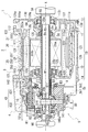
- FIG. 2 is a schematic cross-sectional view illustrating the power transmission device 1 according to the present embodiment.
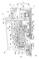
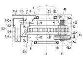
- FIG. 3 is an enlarged view around the planetary reduction gear 4 of the power transmission device 1.
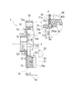
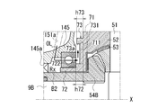
- FIG. 4 is an enlarged view of the power transmission device 1 around the differential mechanism 5.
- the power transmission device 1 includes a motor 2 and a planetary reduction gear 4 (reduction mechanism) that decelerates the output rotation of the motor 2 and inputs it to the differential mechanism 5.
- the power transmission device 1 also has a drive shaft 9 and a park lock mechanism 3.
- the drive shaft 9 has a drive shaft 9A (second drive shaft) and a drive shaft 9B (first drive shaft).
- the park lock mechanism 3, the planetary reduction gear 4, the differential mechanism 5, and the drive shafts 9 (9A, 9B) are arranged along the transmission path of the output rotation around the rotation axis X of the motor 2. , Are provided.
- the axis of the drive shaft 9 (9A, 9B) is coaxial with the rotation axis X of the motor 2.
- the power transmission device 1 After the output rotation of the motor 2 is decelerated by the planetary reduction gear 4 and input to the differential mechanism 5, the power transmission device 1 is mounted via the drive shafts 9 (9A, 9B). It is transmitted to the left and right drive wheels W and W of the vehicle.
- the planetary reduction gear 4 is connected downstream of the motor 2
- the differential mechanism 5 is connected downstream of the planetary reduction gear 4
- the drive shafts 9 (9A, 9B) are differential mechanisms. It is connected downstream of 5.
- the main body box 10 of the power transmission device 1 has a first box 11 that houses the motor 2 and a second box 12 that is externally inserted into the first box 11.
- the main body box 10 also has a third box 13 assembled to the first box 11 and a fourth box 14 assembled to the second box 12.
- the first box 11 has a cylindrical support wall portion 111 and a flange-shaped joint portion 112 provided at one end 111a of the support wall portion 111.
- the first box 11 is provided with the support wall portion 111 oriented along the rotation axis X of the motor 2.
- the motor 2 is housed inside the support wall portion 111.
- the joint portion 112 is provided in a direction orthogonal to the rotation axis X.
- the joint portion 112 is formed with an outer diameter larger than that of the support wall portion 111.
- the second box 12 includes a cylindrical peripheral wall portion 121, a flange-shaped joint portion 122 provided at one end 121a of the peripheral wall portion 121, and a flange-shaped joint portion 123 provided at the other end 121b of the peripheral wall portion 121. ,have.
- the peripheral wall portion 121 is formed with an inner diameter that can be extrapolated to the support wall portion 111 of the first box 11.
- the first box 11 and the second box 12 are assembled to each other by externally inserting the peripheral wall portion 121 of the second box 12 into the support wall portion 111 of the first box 11.
- the joint portion 122 on the one end 121a side of the peripheral wall portion 121 is in contact with the joint portion 112 of the first box 11 from the rotation axis X direction. These joints 122 and 112 are connected to each other by bolts (not shown).
- a plurality of concave grooves 111b are provided on the outer periphery of the support wall portion 111.
- the plurality of concave grooves 111b are provided at intervals in the rotation axis X direction.
- Each of the concave grooves 111b is provided over the entire circumference in the circumferential direction around the rotation axis X.
- the peripheral wall portion 121 of the second box 12 is externally inserted into the support wall portion 111 of the first box 11.
- the opening of the concave groove 111b is closed by the peripheral wall portion 121.
- a plurality of cooling passages CP through which cooling water flows are formed between the support wall portion 111 and the peripheral wall portion 121.
- ring grooves 111c and 111c are formed on both sides of the region where the concave groove 111b is provided.
- Seal rings 113 and 113 are fitted and attached to the ring grooves 111c and 111c. These seal rings 113 are pressed against the inner circumference of the peripheral wall portion 121 extrapolated to the support wall portion 111 to seal the gap between the outer circumference of the support wall portion 111 and the inner circumference of the peripheral wall portion 121.
- the other end 121b of the second box 12 is provided with a wall portion 120 extending toward the inner diameter side.
- the wall portion 120 is provided in a direction orthogonal to the rotation axis X.
- An opening 120a through which the drive shaft 9A is inserted is opened in a region of the wall portion 120 that intersects with the rotation axis X.
- a tubular motor support portion 125 surrounding the opening 120a is provided on the surface on the motor 2 side (right side in the drawing).
- the motor support portion 125 is inserted inside the coil end 253b described later.
- the motor support portion 125 faces the end portion 21b of the rotor core 21 with a gap in the rotation axis X direction.
- the peripheral wall portion 121 of the second box 12 is thicker in the radial direction than in the upper region in the lower region in the vertical direction with respect to the mounted state of the power transmission device 1 in the vehicle.
- An oil reservoir 128 is provided so as to penetrate in the rotation axis X direction in the thick region in the radial direction.
- the oil reservoir 128 communicates with the axial oil passage 138 provided at the joint 132 of the third box 13 via the communication hole 112a.
- the communication hole 112a is provided in the joint portion 112 of the first box 11.
- the third box 13 has a wall portion 130 orthogonal to the rotation axis X.
- a ring-shaped joint 132 is provided on the outer periphery of the wall 130 when viewed from the rotation axis X direction.
- the third box 13 is located on the opposite side (right side in the drawing) of the differential mechanism 5 when viewed from the first box 11.
- the joint portion 132 of the third box 13 is joined to the joint portion 112 of the first box 11 from the rotation axis X direction.
- the third box 13 and the first box 11 are connected to each other by bolts (not shown). In this state, in the first box 11, the opening of the support wall portion 111 on the joint portion 122 side (right side in the drawing) is closed by the third box 13.
- an insertion hole 130a for the drive shaft 9A is provided in the central portion of the wall portion 130.
- a lip seal RS is provided on the inner circumference of the insertion hole 130a.
- a lip portion (not shown) is elastically brought into contact with the outer circumference of the drive shaft 9A.
- the gap between the inner circumference of the insertion hole 130a and the outer circumference of the drive shaft 9A is sealed by the lip seal RS.
- a peripheral wall portion 131 surrounding the insertion hole 130a is provided on the surface of the wall portion 130 on the side of the first box 11 (left side in the drawing).
- a drive shaft 9A is supported on the inner circumference of the peripheral wall portion 131 via a bearing B4.
- a motor support portion 135 is provided on the motor 2 side (left side in the drawing) when viewed from the peripheral wall portion 131.
- the motor support portion 135 has a tubular shape that surrounds the rotation shaft X at intervals.
- a cylindrical connecting wall 136 is connected to the outer circumference of the motor support portion 135.
- the connecting wall 136 is formed with an outer diameter larger than that of the peripheral wall portion 131 on the wall portion 130 side (right side in the drawing).
- the connection wall 136 is provided in a direction along the rotation axis X, and extends in a direction away from the motor 2.
- the connection wall 136 connects the motor support portion 135 and the wall portion 130 of the third box 13.
- the motor support portion 135 is supported by the third box 13 via the connecting wall 136.
- One end 20a side of the motor shaft 20 penetrates the inside of the motor support portion 135 from the motor 2 side to the peripheral wall portion 131 side.
- a bearing B1 is supported on the inner circumference of the motor support portion 135.
- the outer circumference of the motor shaft 20 is supported by the motor support portion 135 via the bearing B1.
- a lip seal RS is provided at a position adjacent to the bearing B1.
- an oil hole 136a which will be described later, is opened on the inner circumference of the connecting wall 136.
- the oil OL flows into the space (internal space Sc) surrounded by the connecting wall 136 from the oil hole 136a.
- the lip seal RS is provided to prevent the oil OL in the connecting wall 136 from flowing into the motor 2 side.
- the fourth box 14 has a peripheral wall portion 141 surrounding the outer periphery of the planetary reduction gear 4 and the differential mechanism 5, and a flange-shaped joint portion 142 provided at the end portion of the peripheral wall portion 141 on the second box 12 side. doing.
- the fourth box 14 functions as a box for accommodating the planetary reduction gear 4 and the differential mechanism 5.
- the fourth box 14 is located on the differential mechanism 5 side (left side in the drawing) when viewed from the second box 12.
- the joint portion 142 of the fourth box 14 is joined to the joint portion 123 of the second box 12 from the rotation axis X direction.
- the fourth box 14 and the second box 12 are connected to each other by bolts (not shown).
- a motor chamber Sa accommodating the motor 2 and a gear chamber Sb accommodating the planetary reduction gear 4 and the differential mechanism 5 are formed inside the main body box 10 of the power transmission device 1.
- the motor chamber Sa is formed inside the first box 11 between the wall portion 120 of the second box 12 and the wall portion 130 of the third box 13.
- the gear chamber Sb is formed on the inner diameter side of the fourth box 14 between the wall portion 120 of the second box 12 and the peripheral wall portion 141 of the fourth box 14.
- a plate member 8 is provided inside the gear chamber Sb.
- the plate member 8 is fixed to the fourth box 14.
- the plate member 8 divides the gear chamber Sb into a first gear chamber Sb1 accommodating the planetary reduction gear 4 and the differential mechanism 5 and a second gear chamber Sb2 accommodating the park lock mechanism 3.
- the second gear chamber Sb2 is located between the first gear chamber Sb1 and the motor chamber Sa in the X direction of the rotation axis.
- the motor 2 has a cylindrical motor shaft 20, a cylindrical rotor core 21 extrapolated to the motor shaft 20, and a stator core 25 that surrounds the outer circumference of the rotor core 21 at intervals.
- bearings B1 and B1 are extrapolated and fixed on both sides of the rotor core 21.
- the bearing B1 located on one end 20a side (right side in the drawing) of the motor shaft 20 as viewed from the rotor core 21 is supported on the inner circumference of the motor support portion 135 of the third box 13.
- the bearing B1 located on the other end 20b side is supported on the inner circumference of the cylindrical motor support portion 125 of the second box 12.
- the motor support portions 135 and 125 are arranged on the inner diameter side of the coil ends 253a and 253b, which will be described later, with one end 21a and the other end 21b of the rotor core 21 facing each other with a gap in the rotation axis X direction. ing.
- the rotor core 21 is formed by laminating a plurality of silicon steel plates. Each of the silicon steel plates is extrapolated to the motor shaft 20 in a state where the relative rotation with the motor shaft 20 is restricted.
- the silicon steel plate has a ring shape when viewed from the rotation axis X direction of the motor shaft 20. On the outer peripheral side of the silicon steel plate, magnets of N pole and S pole (not shown) are alternately provided in the circumferential direction around the rotation axis X.
- the stator core 25 that surrounds the outer circumference of the rotor core 21 is formed by laminating a plurality of electromagnetic steel sheets.
- the stator core 25 is fixed to the inner circumference of the cylindrical support wall portion 111 of the first box 11.
- Each of the electrical steel sheets has a ring-shaped yoke portion 251 fixed to the inner circumference of the support wall portion 111, and a teeth portion 252 protruding from the inner circumference of the yoke portion 251 toward the rotor core 21.
- the stator core 25 having a configuration in which the winding 253 is distributed and wound across a plurality of teeth portions 252 is adopted.
- the stator core 25 is longer in the rotation axis X direction than the rotor core 21 by the amount of the coil ends 253a and 253b protruding in the rotation axis X direction.
- stator core having a configuration in which windings are centrally wound may be adopted for each of the plurality of tooth portions 252 protruding toward the rotor core 21 side.
- the wall portion 120 (motor support portion 125) of the second box 12 is provided with an opening 120a.
- the other end 20b side of the motor shaft 20 penetrates the opening 120a to the differential mechanism 5 side (left side in the drawing) and is located in the fourth box 14.
- the other end 20b of the motor shaft 20 faces the side gear 54A, which will be described later, with a gap in the rotation axis X direction inside the fourth box 14.
- a step portion 201 is provided in a region located in the fourth box 14.
- the step portion 201 is located in the vicinity of the motor support portion 125.
- a lip seal RS supported on the inner circumference of the motor support portion 125 is in contact with the outer periphery of the region between the step portion 201 and the bearing B1.
- the lip seal RS separates the motor chamber Sa accommodating the motor 2 and the gear chamber Sb in the fourth box 14.
- An oil OL for lubricating the planetary reduction gear 4 and the differential mechanism 5 is sealed in the inner diameter side of the fourth box 14 (see FIG. 2).
- the lip seal RS is provided to prevent the inflow of oil OL into the motor chamber Sa.
- the region from the step portion 201 to the vicinity of the other end 20b is a fitting portion 202 provided with a spline on the outer periphery.
- a park gear 30 and a sun gear 41 are spline-fitted on the outer circumference of the fitting portion 202.
- one side surface of the park gear 30 in the X direction of the rotation axis is in contact with the step portion 201 (right side in the drawing).
- One end 410a of the cylindrical base 410 of the sun gear 41 is in contact with the other side surface of the park gear 30 (left side in the figure).
- a nut N screwed into the other end 20b of the motor shaft 20 is in pressure contact with the other end 410b of the base portion 410 from the rotation axis X direction.
- the sun gear 41 and the park gear 30 are provided so as not to rotate relative to the motor shaft 20 in a state of being sandwiched between the nut N and the step portion 201.
- the sun gear 41 has a tooth portion 411 on the outer periphery of the motor shaft 20 on the other end 20b side.
- a large-diameter gear portion 431 of the stepped pinion gear 43 as a pinion gear meshes with the outer periphery of the tooth portion 411.
- the stepped pinion gear 43 has a large-diameter gear portion 431 that meshes with the sun gear 41 and a small-diameter gear portion 432 having a diameter smaller than that of the large-diameter gear portion 431.
- the stepped pinion gear 43 is a gear component in which a large-diameter gear portion 431 and a small-diameter gear portion 432 are integrally provided side by side in the direction of the axis X1 parallel to the rotation axis X.
- the large-diameter gear portion 431 is formed with an outer diameter R1 larger than the outer diameter R2 of the small-diameter gear portion 432.
- the stepped pinion gear 43 is provided in a direction along the axis X1. In this state, the large-diameter gear portion 431 is located on the motor 2 side (on the right side in the drawing).
- the outer circumference of the small diameter gear portion 432 meshes with the inner circumference of the ring gear 42.
- the ring gear 42 has a ring shape that surrounds the rotation shaft X at intervals.
- a plurality of engaging teeth 421 protruding outward in the radial direction are provided on the outer periphery of the ring gear 42.
- a plurality of engaging teeth 421 are provided at predetermined intervals in the circumferential direction around the rotation axis X.
- the engaging teeth 421 provided on the outer circumference are spline-fitted to the tooth portions 146a provided on the support wall portion 146 of the fourth box 14.
- the ring gear 42 is restricted from rotating around the rotation axis X.
- the stepped pinion gear 43 has a through hole 430 that penetrates the inner diameter side of the large-diameter gear portion 431 and the small-diameter gear portion 432 in the axis X1 direction.
- the stepped pinion gear 43 is rotatably supported on the outer periphery of the pinion shaft 44 penetrating the through hole 430 via needle bearings NB and NB as bearings.
- an intermediate spacer MS is interposed between the needle bearing NB that supports the inner circumference of the large-diameter gear portion 431 and the needle bearing NB that supports the inner circumference of the small-diameter gear portion 432. ..
- an in-shaft oil passage 440 is provided inside the pinion shaft 44.
- the in-shaft oil passage 440 penetrates from one end 44a of the pinion shaft 44 to the other end 44b along the axis X1.
- the pinion shaft 44 is provided with oil holes 442 and 443 that communicate the in-shaft oil passage 440 and the outer circumference of the pinion shaft 44.
- the oil hole 443 opens in the region where the needle bearing NB that supports the inner circumference of the large-diameter gear portion 431 is provided.
- the oil hole 442 is open in the region where the needle bearing NB that supports the inner circumference of the small diameter gear portion 432 is provided.
- the oil holes 443 and 442 are opened in the region where the stepped pinion gear 43 is extrapolated.
- the pinion shaft 44 is provided with an introduction path 441 for introducing the oil OL into the in-shaft oil passage 440.
- the introduction path 441 is open to a region located in the support hole 71a of the second case portion 7, which will be described later.
- the introduction path 441 communicates the in-shaft oil passage 440 with the outer circumference of the pinion shaft 44.
- An oil passage 781 in the case is opened on the inner circumference of the support hole 71a.
- the oil passage 781 in the case communicates the outer circumference of the guide portion 78 protruding from the base portion 71 of the second case portion 7 on the rotation axis X side with the inner circumference of the support hole 71a.
- the oil passage 781 in the case is inclined with respect to the axis X1.
- the oil passage 781 in the case is inclined toward the rotation axis X side toward the slit-shaped oil hole 710 provided in the base 71.
- the oil OL scraped up by the differential case 50 flows into the oil passage 781 in the case.
- the oil OL that moves to the outer diameter side due to the centrifugal force due to the rotation of the differential case 50 also flows into the oil passage 781 inside the case.
- the oil OL that has flowed from the oil passage 781 in the case into the introduction passage 441 flows into the in-shaft oil passage 440 of the pinion shaft 44.
- the oil OL that has flowed into the in-shaft oil passage 440 is discharged radially outward from the oil holes 442 and 443.
- the oil OL discharged from the oil holes 442 and 443 lubricates the needle bearing NB extrapolated to the pinion shaft 44.
- a through hole 444 is provided on the other end 44b side of the region where the introduction path 441 is provided.
- the through hole 444 penetrates the pinion shaft 44 in the diameter line direction.
- the pinion shaft 44 is provided so that the through hole 444 and the insertion hole 782 on the second case portion 7 side, which will be described later, are in phase with each other around the axis X1.
- the positioning pin P inserted into the insertion hole 782 penetrates the through hole 444 of the pinion shaft 44.
- the pinion shaft 44 is supported on the second case portion 7 side in a state where rotation around the axis X1 is restricted.
- the region protruding from the stepped pinion gear 43 is the first shaft portion 445.
- the first shaft portion 445 is supported by a support hole 61a provided in the first case portion 6 of the differential case 50.
- a region protruding from the stepped pinion gear 43 is the second shaft portion 446.
- the second shaft portion 446 is supported by a support hole 71a provided in the second case portion 7 of the differential case 50.
- the first shaft portion 445 means a region on the pinion shaft 44 on the one end 44a side where the stepped pinion gear 43 is not extrapolated.
- the second shaft portion 446 means a region on the other end 44b side of the pinion shaft 44 where the stepped pinion gear 43 is not extrapolated.
- the length of the second shaft portion 446 in the axis X1 direction is longer than that of the first shaft portion 445.
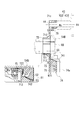
- FIG. 5 is a perspective view of the differential mechanism 5 around the differential case 50.
- FIG. 6 is an exploded perspective view of the differential mechanism 5 around the differential case 50.
- the differential case 50 as a case accommodates the differential mechanism 5.
- the differential case 50 is formed by assembling the first case portion 6 and the second case portion 7 in the rotation axis X direction.
- the first case portion 6 and the second case portion 7 of the differential case 50 have a function as a carrier for supporting the pinion shaft 44 of the planetary reduction gear 4.
- three pinion mate gears 52 and three pinion mate shafts 51 are provided between the first case portion 6 and the second case portion 7 of the differential case 50.
- the pinion mate shaft 51 functions as a support shaft for supporting the pinion mate gear 52.
- the pinion mate shafts 51 are provided at equal intervals in the circumferential direction around the rotation axis X (see FIG. 6). Each inner diameter end of the pinion mate shaft 51 is connected to a common connecting portion 510.
- One pinion mate gear 52 is extrapolated to each of the pinion mate shaft 51.
- Each of the pinion mate gears 52 is in contact with the connecting portion 510 from the radial outside of the rotating shaft X. In this state, each of the pinion mate gears 52 is rotatably supported by the pinion mate shaft 51.
- a spherical washer 53 is extrapolated to the pinion mate shaft 51.
- the spherical washer 53 is in contact with the spherical outer circumference of the pinion mate gear 52.
- the side gear 54A is located on one side of the connecting portion 510 in the rotation axis X direction, and the side gear 54B is located on the other side.
- the side gear 54A is rotatably supported by the first case portion 6.
- the side gear 54B is rotatably supported by the second case portion 7.
- the side gear 54A meshes with three pinion mate gears 52 from one side in the rotation axis X direction.
- the side gear 54B meshes with the three pinion mate gears 52 from the other side in the rotation axis X direction.
- FIG. 7 to 10 are views for explaining the first case portion 6.
- FIG. 7 is a perspective view of the first case portion 6 as viewed from the second case portion 7 side.
- FIG. 8 is a plan view of the first case portion 6 as viewed from the second case portion 7 side.
- FIG. 9 is a schematic view of a cross section taken along the line AA in FIG.
- FIG. 9 shows the arrangement of the pinion mate shaft 51 and the pinion mate gear 52 with virtual lines.
- FIG. 10 is a schematic view of a cross section taken along the line AA in FIG. In FIG. 10, the arrangement of the side gear 54A, the stepped pinion gear 43, and the drive shaft 9A is shown by a virtual line while omitting the illustration of the connecting beam 62 on the back side of the paper.
- the first case portion 6 has a ring-shaped base portion 61.
- the base portion 61 is a plate-shaped member having a thickness W61 in the rotation axis X direction.
- an opening 60 is provided in the central portion of the base portion 61.
- a tubular wall portion 611 surrounding the opening 60 is provided on the surface of the base portion 61 opposite to the second case portion 7 (on the right side in the drawing). The outer circumference of the tubular wall portion 611 is supported by a plate member 8 via a bearing B3 (see FIG. 2).
- Three connecting beams 62 extending to the second case portion 7 side are provided on the surface of the base portion 61 on the second case portion 7 side (left side in the drawing).
- the connecting beams 62 are provided at equal intervals in the circumferential direction around the rotation axis X (see FIGS. 7 and 8).
- the connecting beam 62 has a base portion 63 orthogonal to the base portion 61 and a connecting portion 64 wider than the base portion 63.
- the tip surface 64a of the connecting portion 64 is a flat surface orthogonal to the rotation axis X.
- the tip surface 64a is provided with a support groove 65 for supporting the pinion mate shaft 51.
- the support groove 65 is formed in a straight line along the radius line L of the ring-shaped base portion 61 when viewed from the rotation axis X direction.
- the support groove 65 crosses the central portion of the connecting portion 64 in the circumferential direction around the rotation axis X from the inner diameter side to the outer diameter side.
- the support groove 65 has a semicircular shape along the outer diameter of the pinion mate shaft 51.
- An arc portion 641 is formed on the inner diameter side (rotation shaft X side) of the connecting portion 64 in a shape along the outer circumference of the pinion mate gear 52.
- the outer circumference of the pinion mate gear 52 is supported via the spherical washer 53.
- an oil groove 642 is provided in a direction along the radius line L described above. The oil groove 642 is provided in a range from the support groove 65 of the pinion mate shaft 51 to the gear support portion 66 fixed to the inner circumference of the connecting portion 64.
- the gear support portion 66 is connected to a boundary portion between the base portion 63 and the connecting portion 64.
- the gear support portion 66 is provided in a direction orthogonal to the rotation axis X.
- the gear support portion 66 has a through hole 660 in the central portion. As shown in FIG. 8, the outer circumference of the gear support portion 66 is connected to the inner circumference of the three connecting portions 64. In this state, the center of the through hole 660 is located on the rotation axis X.
- the gear support portion 66 is provided with a recess 661 surrounding the through hole 660 on the surface opposite to the base portion 61 (left side in the drawing).
- a ring-shaped washer 55 that supports the back surface of the side gear 54A is housed in the recess 661.
- a cylindrical wall portion 541 is provided on the back surface of the side gear 54A. The washer 55 is extrapolated to the cylinder wall portion 541.
- Oil grooves 662 are provided on the surface of the gear support portion 66 on the recess 661 side when viewed from the rotation axis X direction. Oil grooves 662 are provided at predetermined intervals in the circumferential direction around the rotation axis X. The oil groove 662 extends from the inner circumference to the outer circumference of the gear support portion 66 along the radius line L described above. The oil groove 662 communicates with the oil groove 642 on the arc portion 641 side described above.
- a support hole 61a of the pinion shaft 44 is opened in the base portion 61.
- the support holes 61a are open in the region between the connecting beams 62, 62 arranged at intervals in the circumferential direction around the rotation axis X.
- the base portion 61 is provided with a boss portion 616 that surrounds the support hole 61a.
- a washer Wc (see FIG. 10) extrapolated to the pinion shaft 44 comes into contact with the boss portion 616 from the rotation axis X direction.
- an oil groove 617 is provided in a range from the central opening 60 to the boss portion 616.
- the oil groove 617 is formed in a tapered shape in which the width in the circumferential direction around the rotation axis X becomes narrower as it approaches the boss portion 616.
- the oil groove 617 is in contact with the oil groove 618 provided in the boss portion 616.
- bolt holes 67 and 67 are provided on both sides of the support groove 65.
- a connecting portion 74 on the side of the second case portion 7 is joined to the connecting portion 64 of the first case portion 6 from the rotation axis X direction.
- bolts B penetrating the connecting portion 74 on the second case portion 7 side are screwed into the bolt holes 67 and 67 and joined to each other.
- FIG. 11 to 20 are views for explaining the second case portion 7.
- FIG. 11 is a perspective view of the second case portion 7 as viewed from the first case portion 6 side.
- FIG. 12 is a plan view of the second case portion 7 as viewed from the first case portion 6 side.
- FIG. 13 is a schematic view of a cross section taken along the line AA in FIG.
- FIG. 13 shows the arrangement of the pinion mate shaft 51 and the pinion mate gear 52 by a virtual line.
- FIG. 14 is a schematic view of a cross section taken along the line AA in FIG. In FIG. 14, the arrangement of the side gear 54B, the stepped pinion gear 43, and the drive shaft 9B is shown by a virtual line while omitting the illustration of the connecting portion 74 on the back side of the paper.
- FIG. 14 is a schematic view of a cross section taken along the line AA in FIG. In FIG. 14, the arrangement of the side gear 54B, the stepped pinion gear 43, and the drive shaft 9B is shown
- FIG. 15 is a perspective view of the second case portion 7 as viewed from the side opposite to the first case portion 6.
- FIG. 16 is a plan view of the second case portion 7 as viewed from the side opposite to the first case portion 6.
- FIG. 17 is a schematic view of a cross section taken along the line AA in FIG.
- FIG. 18 is a schematic view of a cross section taken along the line BB in FIG.
- FIG. 19 is a schematic view of a CC cross section in FIG.
- FIG. 20 is a diagram illustrating the operation of the rib 711.
- the second case portion 7 has a ring-shaped base portion 71.
- the base portion 71 is a plate-shaped member having a thickness W71 in the rotation axis X direction.
- a through hole 70 that penetrates the base portion 71 in the thickness direction is provided in the central portion of the base portion 71.
- a step portion 722 is provided on the outer periphery of the cylinder wall portion 72.
- the outer diameter of the tubular wall portion 72 is larger on the base portion 71 side than on the tip end side.
- the height h72 from the base portion 71 to the step portion 722 is higher than the height h73 from the base portion 71 to the guide portion 73 (h73 ⁇ h72).
- a protrusion 73a protruding toward the rotation shaft X side is provided at the tip of the guide portion 73.
- the protrusion 73a is provided over the entire circumference in the circumferential direction around the rotation axis X.
- three support holes 71a of the pinion shaft 44 are opened on the outer diameter side of the guide portion 73.
- the support holes 71a are provided at intervals in the circumferential direction around the rotation axis X.
- On the inner diameter side of the guide portion 73 three oil holes 710 that penetrate the base portion 71 in the thickness direction are provided.
- the oil hole 710 opens toward the outside of the differential case 50 in the X direction of the rotation axis.
- the oil hole 710 is formed in an arc shape along the inner circumference of the guide portion 73 when viewed from the rotation axis X direction.
- the oil holes 710 are formed in a predetermined angle range in the circumferential direction around the rotation axis X. As shown in FIG. 13, the outer peripheral edge of the oil hole 710 is flush with the inner peripheral surface 731 of the guide portion 73.
- the oil holes 710 are provided at intervals in the circumferential direction around the rotation axis X.
- Each of the oil holes 710 is provided across the inner diameter side of the support hole 71a in the circumferential direction around the rotation axis X.
- a rib 711 protruding toward the front side of the paper surface is provided between the oil holes 710 and 710 adjacent to each other in the circumferential direction around the rotation axis X.
- the rib 711 extends linearly in the radial direction of the rotation axis X.
- the rib 711 is provided so as to straddle the guide portion 73 on the outer diameter side and the cylinder wall portion 72 on the inner diameter side.
- recessed grooves 711a and 711b are formed on one side and the other side of the rib 711 in the circumferential direction around the rotation axis X.
- These concave grooves 711a and 711b are formed in a range from the cylinder wall portion 72 on the inner diameter side to the protrusion 73a of the guide portion 73.
- the three ribs 711 are provided at intervals in the circumferential direction around the rotation axis X.
- the three ribs 711 are provided so as to be out of phase with respect to the oil hole 710 in the circumferential direction around the rotation axis X by approximately 45 degrees.
- bolt accommodating portions 76, 76 recessed on the inner side of the paper surface are provided between the support holes 71a, 71a adjacent to each other in the circumferential direction around the rotation axis X. These bolt accommodating portions 76, 76 are provided in a symmetrical positional relationship with a radius line L in between.
- the bolt accommodating portion 76 is open to the outer circumference 71c of the base portion 71.
- a bolt insertion hole 77 is opened inside the bolt accommodating portion 76. The insertion hole 77 penetrates the base 71 in the thickness direction (rotation axis X direction).
- three connecting portions 74 projecting to the first case portion 6 side are provided on the surface of the base portion 71 on the first case portion 6 side (right side in the drawing).
- the connecting portions 74 are provided at equal intervals in the circumferential direction around the rotation axis X.
- the connecting portion 74 is formed with a width W7 in the same circumferential direction as the connecting portion 64 on the first case portion 6 side.
- the tip surface 74a of the connecting portion 74 is a flat surface orthogonal to the rotation axis X.
- the tip surface 74a is provided with a support groove 75 for supporting the pinion mate shaft 51.
- the support groove 75 is formed linearly along the radius line L of the base 71 when viewed from the rotation axis X direction.
- the support groove 75 is formed so as to cross the connecting portion 74 from the inner diameter side to the outer diameter side.
- the support groove 75 has a semicircular shape along the outer diameter of the pinion mate shaft 51.
- An arc portion 741 along the outer circumference of the pinion mate gear 52 is provided on the inner diameter side (rotation shaft X side) of the connecting portion 74.
- the outer circumference of the pinion mate gear 52 is supported via the spherical washer 53 (see FIGS. 13 and 14).
- the oil groove 742 is provided in the direction along the radius line L described above.
- the oil groove 742 is provided in a range from the support groove 75 of the pinion mate shaft 51 to the base portion 71 located on the inner circumference of the connecting portion 74.
- the oil groove 742 communicates with the oil groove 712 provided on the surface 71b of the base 71.
- the oil groove 712 is provided along the radius line L when viewed from the rotation axis X direction, and is formed up to the through hole 70 provided in the base portion 71.
- a ring-shaped washer 55 that supports the back surface of the side gear 54B is placed on the surface 71b of the base portion 71.
- a cylindrical wall portion 540 is provided on the back surface of the side gear 54B. The washer 55 is extrapolated to the cylinder wall portion 540.
- An oil groove 721 is formed at a position intersecting the oil groove 712 on the inner circumference of the tubular wall portion 72 surrounding the through hole 70. On the inner circumference of the cylinder wall portion 72, an oil groove 721 is provided along the rotation axis X over the entire length of the cylinder wall portion 72 in the rotation axis X direction.
- a guide portion 78 is provided between the connecting portions 74 and 74 adjacent to each other in the circumferential direction around the rotation axis X.
- the guide portion 78 projects toward the first case portion 6 side (front side of the paper surface).
- the guide portion 78 has a tubular shape when viewed from the rotation axis X direction.
- the guide portion 78 surrounds the support hole 71a provided in the base portion 71.
- the outer peripheral portion of the guide portion 78 is cut along the outer peripheral portion 71c of the base portion 71.
- the pinion shaft 44 is inserted into the support hole 71a of the guide portion 78 from the side of the first case portion 6 in the cross-sectional view along the axis X1.
- the pinion shaft 44 is positioned in a state where rotation around the axis X1 is restricted by the positioning pin P. In this state, the small-diameter gear portion 432 of the stepped pinion gear 43 extrapolated to the pinion shaft 44 is in contact with the guide portion 78 from the axis X1 direction with the washer Wc sandwiched between them.
- the bearing B2 is extrapolated to the cylinder wall portion 72 of the second case portion 7.
- the bearing B2 has an inner race in contact with a step portion 722 provided on the outer periphery of the cylinder wall portion 72 from the rotation axis X direction.
- the bearing B2 extrapolated to the cylinder wall portion 72 is held by the support portion 145 of the fourth box 14.
- the tubular wall portion 72 of the differential case 50 is rotatably supported by the fourth box 14 via the bearing B2.
- a drive shaft 9B penetrating the opening 145a of the fourth box 14 is inserted into the support portion 145 from the rotation axis X direction.
- the drive shaft 9B is rotatably supported by the support portion 145.
- the cylinder wall portion 72 functions as a shaft support portion that supports the outer circumference of the drive shaft 9B.
- a lip seal RS is fixed to the inner circumference of the opening 145a.
- a lip portion (not shown) of the lip seal RS is elastically in contact with the outer circumference of the cylinder wall portion 540 of the side gear 54B extrapolated to the drive shaft 9B. As a result, the gap between the outer circumference of the cylinder wall portion 540 of the side gear 54B and the inner circumference of the opening 145a is sealed.
- the first case portion 6 of the differential case 50 is supported by the plate member 8 via the bearing B3 extrapolated to the cylinder wall portion 611 (see FIG. 2).
- a drive shaft 9A penetrating the insertion hole 130a of the third box 13 is inserted from the rotation axis X direction.
- the drive shaft 9A is provided across the motor shaft 20 of the motor 2 and the inner diameter side of the sun gear 41 of the planetary reduction gear 4 in the rotation axis X direction.
- side gears 54A and 54B are spline-fitted on the outer periphery of the tip of the drive shaft 9 (9A, 9B).
- the side gears 54A and 54B and the drive shafts 9 (9A and 9B) are integrally rotatably connected around the rotation shaft X.
- the side gears 54A and 54B are arranged to face each other at intervals in the rotation axis X direction.
- the connecting portion 510 of the pinion mate shaft 51 is located between the side gears 54A and 54B.
- a total of three pinion mate shafts 51 extend radially outward from the connecting portion 510.
- a pinion mate gear 52 is supported on each of the pinion mate shafts 51.
- the pinion mate gear 52 is assembled to the side gear 54A located on one side in the rotation axis X direction and the side gear 54B located on the other side in a state where the teeth are meshed with each other.
- the lubricating oil OL is stored inside the fourth box 14.
- the lower side of the differential case 50 is located in the stored oil OL.
- the oil OL is stored up to the height at which the connecting beam 62 is located in the oil OL.
- the stored oil OL is scraped up by the differential case 50 that rotates around the rotation axis X when the output rotation of the motor 2 is transmitted.
- FIG. 21 to 26 are views for explaining the oil catch portion 15.
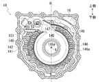
- FIG. 21 is a plan view of the fourth box 14 as viewed from the third box 13 side.
- FIG. 22 is a perspective view of the oil catch portion 15 shown in FIG. 21 as viewed from diagonally above.
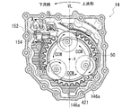
- FIG. 23 is a plan view of the fourth box 14 as viewed from the third box 13 side, and is a view showing a state in which the differential case 50 is arranged.
- FIG. 24 is a perspective view of the oil catch portion 15 shown in FIG. 23 as viewed from diagonally above.
- FIG. 25 is a schematic view of a cross section taken along the line AA in FIG. 23.
- 26 is a schematic view illustrating the positional relationship between the oil catch portion 15 and the differential case 50 (first case portion 6, second case portion 7) when the power transmission device 1 is viewed from above.
- hatching is added in order to clarify the positions of the joint portion 142 of the fourth box 14 and the support wall portion 146.
- the fourth box 14 when viewed from the rotation axis X direction is provided with support wall portions 146 that surround the central opening 145a at predetermined intervals.
- the inside (rotation axis X) side of the support wall portion 146 is the accommodating portion 140 of the differential case 50.
- a space for the oil catch portion 15 and a space for the breather chamber 16 are formed in the upper part of the fourth box 14.
- a communication port 147 for communicating the oil catch portion 15 and the accommodating portion 140 of the differential case 50 is provided in the region intersecting the vertical line VL.
- the oil catch portion 15 and the breather chamber 16 are located on one side (left side in the figure) and the other side (right side in the figure) of the vertical line VL orthogonal to the rotation axis X, respectively.
- the oil catch portion 15 is arranged at a position offset from the vertical line VL passing through the rotation center (rotation axis X) of the differential case 50.
- the vertical line VL is a vertical line VL based on the installation state of the power transmission device 1 in the vehicle.
- the vertical line VL when viewed from the rotation axis X direction is orthogonal to the rotation axis X.
- the oil catch portion 15 is formed so as to extend to the back side of the paper surface from the support wall portion 146.
- a support base portion 151 is provided on the lower edge of the oil catch portion 15 so as to project toward the front side of the paper surface.
- the support base portion 151 is provided on the front side of the paper surface of the support wall portion 146 and in the range from the joint portion 142 of the fourth box 14 to the back side of the paper surface.
- a communication port 147 is formed by cutting out a part of the support wall portion 146 on the vertical line VL side (right side in the drawing) of the oil catch portion 15 when viewed from the rotation axis X direction. Has been done.
- the communication port 147 communicates the oil catch portion 15 with the accommodating portion 140 of the differential case 50.
- the communication port 147 is provided in a range that crosses the vertical line VL from the breather chamber 16 side (right side in the figure) to the oil catch portion 15 side (left side in the figure) when viewed from the rotation axis X direction.
- the differential case 50 rotates in the counterclockwise direction CCW around the rotation axis X when viewed from the third box 13 side. .. Therefore, the oil catch portion 15 is located on the downstream side in the rotation direction of the differential case 50.
- the width of the communication port 147 in the circumferential direction is wider on the left side of the vertical line VL than on the right side.
- the left side of the vertical line VL is the downstream side in the rotation direction of the differential case 50, and the right side is the upstream side.
- the outer peripheral position of the rotary orbit of the second shaft portion 446 and the outer peripheral position of the rotary orbit of the large-diameter gear portion 431 are offset in the radial direction of the rotary shaft X.
- the outer peripheral position of the rotary orbit of the second shaft portion 446 is located on the inner diameter side of the outer peripheral position of the rotary orbit of the large-diameter gear portion 431. Therefore, there is a space margin on the outer diameter side of the second shaft portion 446, and by using this space to provide the oil catch portion 15, the space inside the main body box 10 can be effectively used. There is.
- the second shaft portion 446 projects toward the back side of the small diameter gear portion 432 when viewed from the motor 2.
- the peripheral member of the second shaft portion 446 (for example, the guide portion 73 of the differential case 50 that supports the second shaft portion 446) is located close to the oil catch portion 15. Therefore, the oil OL (lubricating oil) can be smoothly supplied from the peripheral member to the oil catch portion 15.
- the guide portion 73 and the oil hole 710 are located on the inner diameter side (rotating shaft X side) of the second shaft portion 446. .. Therefore, the drive shaft 9B is located on the inner diameter side (inner circumference) of the second shaft portion 446. The oil hole 710 is located on the outer diameter side (outer circumference) of the drive shaft 9B. Further, the drive shaft 9A is located on the inner diameter side (inner circumference) of the first shaft portion 445 and the stepped pinion gear 43.
- an end portion on the outer diameter side of the oil passage 151a is opened on the inner side of the support base portion 151.
- the oil passage 151a extends inside the fourth box 14 toward the inner diameter side as an oil passage in the box.
- the inner diameter side end of the oil passage 151a is open to the inner circumference of the support portion 145.
- the end of the oil passage 151a on the inner diameter side of the support portion 145 is open between the lip seal RS and the bearing B2.
- the oil guide 152 is mounted on the support base portion 151.
- the oil guide 152 has a catch portion 153 and a guide portion 154 extending from the catch portion 153 to the first box 11 side (the front side of the paper surface in FIG. 24).
- the support base portion 151 is stepped on the radial side of the rotation axis X at a position overlapping a part of the differential case 50 (first case portion 6, second case portion 7) when viewed from above. It is provided so as to avoid interference with the attached pinion gear 43 (large diameter gear portion 431).
- the catch portion 153 is provided at a position overlapping the second shaft portion 446 of the pinion shaft 44 when viewed from the radial direction of the rotation shaft X.
- the guide portion 154 is provided at a position where it overlaps the first shaft portion 445 of the pinion shaft 44 and the large diameter gear portion 431.
- a wall portion 153a extending in a direction away from the support base portion 151 (upward) is provided on the outer peripheral edge of the catch portion 153.
- a part of the oil OL scraped up by the differential case 50 that rotates around the rotation axis X by the wall portion 153a is stored in the oil guide 152.
- a notch portion 155 is provided in the wall portion 153a.
- the cutout portion 155 is provided in a region facing the oil passage 151a. A part of the oil OL stored in the catch portion 153 is discharged from the notch portion 155 toward the oil passage 151a.
- the guide portion 154 is inclined downward as the distance from the catch portion 153 increases.
- Wall portions 154a and 154a are provided on both sides of the guide portion 154 in the width direction.
- the wall portions 154a and 154a are provided over the entire length of the guide portion 154 in the longitudinal direction.
- the wall portions 154a and 154a are connected to the wall portion 153a surrounding the outer circumference of the catch portion 153. A part of the oil OL stored in the catch portion 153 is also discharged to the guide portion 154 side.
- the guide portion 154 extends toward the second box 12 at a position where it avoids interference with the differential case 50.
- the tip 154b of the guide portion 154 faces the through hole 126a provided in the wall portion 120 of the second box 12 with a gap in the rotation axis X direction.
- a boss portion 126 surrounding the through hole 126a is provided on the outer periphery of the wall portion 120.
- One end of the pipe 127 is fitted into the boss portion 126 from the rotation axis X direction.
- the pipe 127 passes through the outside of the second box 12 and extends to the third box 13.
- the other end of the pipe 127 communicates with an oil hole 136a (see FIG. 2) provided in the cylindrical connecting wall 136 of the third box 13.
- a part of the oil OL that has been scraped up by the differential case 50 that rotates around the rotation axis X and has reached the oil catch portion 15 is supplied to the internal space Sc of the connection wall 136 through the guide portion 154 and the pipe 127. ..
- the third box 13 is provided with a radial oil passage 137 communicating with the internal space Sc.
- the radial oil passage 137 extends radially downward from the internal space Sc.
- the radial oil passage 137 communicates with the axial oil passage 138 provided in the joint portion 132.
- the axial oil passage 138 communicates with the oil reservoir 128 provided at the lower part of the second box 12 via the communication hole 112a provided at the joint portion 112 of the first box 11.
- the oil sump portion 128 penetrates the inside of the peripheral wall portion 121 in the rotation axis X direction.
- the oil sump 128 is in contact with the second gear chamber Sb2 provided in the fourth box 14.
- the operation of the power transmission device 1 having such a configuration will be described.
- the planetary reduction gear 4, the differential mechanism 5, and the drive shafts 9 (9A, 9B) are provided along the transmission path of the output rotation of the motor 2. ing.
- the sun gear 41 is an input unit for the output rotation of the motor 2.
- the differential case 50 that supports the stepped pinion gear 43 serves as an output unit for the input rotation.
- the stepped pinion gear 43 (large diameter gear portion 431, small diameter gear portion 432) rotates around the axis X1 by the rotation input from the sun gear 41 side.
- the small-diameter gear portion 432 of the stepped pinion gear 43 meshes with the ring gear 42 fixed to the inner circumference of the fourth box 14. Therefore, the stepped pinion gear 43 revolves around the rotation axis X while rotating around the axis X1.
- the drive shaft 9B is located on the inner circumference of the revolution orbit of the stepped pinion gear 43.
- the outer diameter R2 of the small-diameter gear portion 432 of the stepped pinion gear 43 is smaller than the outer diameter R1 of the large-diameter gear portion 431 (see FIG. 3).
- the differential case 50 first case portion 6, second case portion 7) that supports the stepped pinion gear 43 rotates around the rotation axis X at a rotation speed lower than the rotation input from the motor 2 side. Therefore, the rotation input to the sun gear 41 of the planetary reduction gear 4 is greatly reduced by the stepped pinion gear 43. The reduced rotation is output to the differential case 50 (differential mechanism 5).
- the lubricating oil OL is stored inside the fourth box 14. Therefore, the stored oil OL is scraped up by the differential case 50 that rotates around the rotation axis X when the output rotation of the motor 2 is transmitted. Due to the oil OL scraped up, the meshing portion between the sun gear 41 and the large diameter gear portion 431, the meshing portion between the small diameter gear portion 432 and the ring gear 42, and the meshing portion between the pinion mate gear 52 and the side gears 54A and 54B. Is lubricated.
- the differential case 50 rotates in the counterclockwise direction CCW around the rotation axis X when viewed from the third box 13 side.
- An oil catch portion 15 is provided on the upper portion of the fourth box 14.
- the oil catch portion 15 is located on the downstream side in the rotation direction of the differential case 50. Most of the oil OL scraped up by the differential case 50 flows into the oil catch portion 15.
- an oil guide 152 mounted on the support base portion 151 is provided in the oil catch portion 15.
- the guide portion 154 and the catch portion 153 of the oil guide 152 are located on the radial outside of the first case portion 6 of the differential case 50 and on the radial outside of the second case portion 7 of the differential case 50. Therefore, most of the oil that has been scraped up by the differential case 50 and has flowed into the oil catch portion 15 is captured by the oil guide 152.
- a part of the oil OL captured by the oil guide 152 is discharged from the notch 155 provided in the wall portion 153a. The discharged oil OL flows into the oil passage 151a having one end opened on the upper surface of the support base portion 151.
- the end of the oil passage 151a on the inner diameter side is open to the inner circumference of the support portion 145 (see FIG. 2). Therefore, the oil OL that has flowed into the oil passage 151a is discharged into the gap Rx between the inner circumference of the support portion 145 of the fourth box 14 and the cylinder wall portion 540 of the side gear 54B.
- the oil OL that lubricates the bearing B2 moves on the outside of the differential case 50 (bearing B2 side) to the outer diameter side by the centrifugal force due to the rotation of the differential case 50 (see FIGS. 17 and 18).
- a guide portion 73 forming an annular shape when viewed from the rotation axis X direction is provided. Therefore, the oil OL that has moved to the outer diameter side is captured by the guide portion 73.
- an oil hole 710 is provided along the inner peripheral surface 731 of the guide portion 73.
- the guide portion 73 prevents the oil OL from further moving to the outer diameter side.
- the oil OL whose movement is hindered passes through the oil hole 710 that opens on the inner circumference of the guide portion 73 toward the first case portion 6 side.
- ribs 711 are provided between the oil holes 710 and 710 adjacent to each other in the circumferential direction around the rotation axis X (see FIG. 16).
- the differential case 50 (second case portion 7) rotates clockwise in the drawing when the vehicle equipped with the power transmission device 1 travels forward.
- the oil OL moves to the outer diameter side by the centrifugal force generated by the rotation of the differential case 50.
- the oil OL that did not directly flow into the oil hole 710 moves to the downstream side in the rotation direction of the differential case 50 while moving to the outer diameter side as shown by the broken line arrow in FIG. 20.
- the rib 711 is located on the downstream side in the rotation direction of the differential case 50. The flow of oil OL that has moved to the downstream side is dammed by the rib 711.
- the area of the oil OL dammed and retained by the rib 711 expands toward the upstream side in the rotation direction of the differential case 50.
- the oil OL that has spread toward the upstream side reaches the oil hole 710 and flows into the oil hole 710.
- recessed grooves 711a and 711b are provided on the side surface of the rib 711. Therefore, most of the oil OL that has reached the rib 711 stays at the rib 711 without getting over the rib 711.
- the concave groove 711a is a portion that contributes to the retention of oil OL when the vehicle equipped with the power transmission device 1 travels forward.
- the concave groove 711b is a portion that contributes to the retention of oil OL when the vehicle equipped with the power transmission device 1 travels backward.
- the guide portion 73 is provided with a protrusion 73a.
- the inner peripheral surface 731 of the protrusion 73a between the second case portion 7 and the base portion 71 functions as an oil groove.
- the oil OL reaches the guide portion 73 by the centrifugal force generated by the rotation of the differential case 50. Most of the oil OL that has reached the guide portion 73 flows into the oil hole 710 that opens in the rotation axis X direction on the side of the inner peripheral surface 731 without getting over the guide portion 73.
- an oil passage 781 in the case is opened on the inner circumference of the guide portion 78 on the side of the first case portion 6 of the oil hole 710.
- a part of the oil OL that has passed through the oil hole 710 flows into the oil passage 781 in the case due to the centrifugal force generated by the rotation of the differential case 50.
- the oil OL that has flowed into the oil passage 781 in the case flows into the in-shaft oil passage 440 of the pinion shaft 44 through the introduction passage 441.
- the oil OL that has flowed into the in-shaft oil passage 440 is discharged radially outward from the oil holes 442 and 443.
- the discharged oil OL lubricates the needle bearing NB extrapolated to the pinion shaft 44.
- the oil passage 781 in the case is inclined with respect to the axis X1 in a direction in which the separation distance Dc from the oil hole 710 becomes shorter toward the rotation axis X side (inner diameter side). ing. Therefore, most of the oil OL that has flowed into the inside of the differential case 50 through the oil hole 710 flows into the oil passage 781 in the case before being diffused by the centrifugal force due to the rotation of the differential case 50.
- a part of the oil OL discharged into the gap Rx passes through the oil groove 721 provided on the inner circumference of the cylinder wall portion 72 of the second case portion 7.
- the oil OL that has passed through the oil groove 721 is supplied to the washer 55 that supports the back surface of the side gear 54B to lubricate the washer 55.
- the oil OL passes through the oil groove 712 provided in the base portion 71 of the second case portion 7 and the oil groove 742 provided in the arc portion 741.
- the oil OL that has passed through the oil groove 742 is supplied to the spherical washer 53 that supports the back surface of the pinion mate gear 52, and lubricates the spherical washer 53.
- a boss portion 126 surrounding the through hole 126a is provided on the outer periphery of the wall portion 120.
- One end of the pipe 127 is fitted into the boss portion 126 from the rotation axis X direction.
- the pipe 127 passes through the outside of the second box 12 and extends to the third box 13.
- the other end of the pipe 127 communicates with an oil hole 136a (see FIG. 2) provided in the cylindrical connection wall 136 of the third box.
- a part of the oil OL that has reached the oil catch portion 15 is supplied to the internal space Sc of the connection wall 136 through the guide portion 154 and the pipe 127.
- the oil OL discharged from the oil hole 136a into the internal space Sc is stored in the internal space Sc.
- the oil OL also lubricates the bearing B4 supported by the peripheral wall portion 131 of the third box 13.
- a part of the oil OL discharged into the internal space Sc moves to the other end 20b side of the motor shaft 20 through the gap between the outer circumference of the drive shaft 9A and the inner circumference of the motor shaft 20.
- the other end 20b of the motor shaft 20 is inserted inside the tubular wall portion 541 of the side gear 54A.
- a connecting path 542 communicating with the back surface of the side gear 54A is provided on the inner circumference of the cylinder wall portion 541. Therefore, a part of the oil OL that has moved to the other end 20b side of the motor shaft 20 and has been discharged to the inside of the cylinder wall portion 541 passes through the connecting path 542.
- the oil OL that has passed through the connecting path 542 is supplied to the washer 55 on the back surface of the side gear 54A to lubricate the washer 55.
- the oil OL that lubricates the washer 55 on the back surface of the side gear 54A passes through the oil groove 662 provided in the gear support portion 66 of the first case portion 6 and the oil groove 642 provided in the arc portion 641.
- the oil OL that has passed through the oil groove 642 is supplied to the spherical washer 53 that supports the back surface of the pinion mate gear 52, and lubricates the spherical washer 53.
- the internal space Sc of the third box 13 includes a radial oil passage 137, an axial oil passage 138, a communication hole 112a, and an oil reservoir provided at the lower part of the second box 12. It communicates with the second gear chamber Sb2 provided in the fourth box 14 via 128. Therefore, the oil OL in the internal space Sc is held at the same height position as the oil OL stored in the fourth box 14.
- the oil OL in the fourth box 14 is scraped up when the drive wheels W and W rotate, and is used for lubrication of the bearing and the meshing portion between the gears.
- the oil OL used for lubrication is returned to the fourth box 14 so that it can be scraped up again.
- the power transmission device 1 has the following configuration.
- the power transmission device 1 is Drive shaft 9A (second drive shaft), drive shaft 9B (first drive shaft), The differential mechanism 5 connected to the drive shafts 9A and 9B, and A differential case 50 (case) accommodating the differential mechanism 5 and having an oil hole 710,
- the pinion shaft 44 supported by the differential case 50 and A stepped pinion gear 43 (pinion gear) centered on the pinion shaft 44, and It has a needle bearing NB (bearing) located between the pinion shaft 44 and the stepped pinion gear 43.
- the oil hole 710 opens toward the outside of the differential case 50, and the needle bearing NB is lubricated with the oil OL supplied via the oil hole 710.
- the oil OL (lubricating oil) on the outside of the differential case 50 is fed into the oil hole 710 that opens toward the outside of the differential case 50.
- the amount of lubrication of the needle bearing NB which is the bearing of the pinion shaft 44, can be increased. That is, by forming the oil hole 710 that opens toward the outside of the differential case 50, the oil OL (lubricating oil) on the outside of the differential case 50, which has not been used conventionally, can be effectively used, and the bearing of the pinion shaft 44 can be used. It becomes possible to increase the lubrication amount of the needle bearing NB.
- the power transmission device 1 has the following configuration. (2)
- the drive shaft 9B is located on the inner circumference of the revolution orbit of the stepped pinion gear 43.
- the oil hole 710 is located on the outer periphery of the drive shaft 9B.
- the oil OL lubricating oil
- the term "position on the outer circumference” in the present specification is synonymous with overlapping in the radial direction on the outside.
- “Position on the inner circumference” is synonymous with overlapping in the radial direction on the inside.
- the power transmission device 1 has the following configuration.
- the power transmission device 1 has a fourth box 14 (box) that houses a stepped pinion gear 43, a differential mechanism 5, and a differential case 50.
- An oil passage 151a oil passage in the box is formed in the fourth box 14 to guide the oil OL (lubricating oil) scooped up by the revolution and / or rotation of the stepped pinion gear 43 to the drive shaft 9B.
- the amount of oil OL (lubricating oil) that is scraped up around the drive shaft 9A is larger than that around the drive shaft 9B. Therefore, by forming the oil passage 151a (oil passage in the box) on the drive shaft 9B side of the fourth box 14, the amount of lubrication to the needle bearing NB that supports the stepped pinion gear 43 can be further increased.
- the power transmission device 1 has the following configuration.
- the oil hole 710 opens outward in the X direction of the rotation axis.
- the oil OL lubricating oil
- the opening surface does not have to be orthogonal to the axial direction. For example, even if the opening surface is slanted, it can be said that the opening surface is open toward the outside in the axial direction if the lubricating oil can be introduced from the axial direction side.
- the power transmission device 1 has the following configuration. (5) In the second case portion 7 of the differential case 50 that supports the drive shaft 9B (second drive shaft), a guide portion arranged on the outer circumference of the cylinder wall portion 72 (shaft support portion) that supports the outer circumference of the drive shaft 9B. 73. The inner peripheral surface 731 of the guide portion 73 is adjacent to the oil hole 710.
- the oil OL (lubricating oil) on the outside of the differential case 50 is moved toward the oil hole 710 and smoothly introduced into the oil hole 710. be able to.
- the guide portion 73 may be integrally formed with the differential case 50, or may be formed separately.
- the inner peripheral surface 731 of the guide portion 73 is adjacent to the oil hole 710.
- the oil OL (lubricating oil) is introduced into the oil hole 710 via the surface of the inner peripheral surface 731 of the guide portion 73.
- the power transmission device 1 has the following configuration. (6)
- the pinion shaft 44 is located on the outer periphery of the drive shafts 9A and 9B. By extending the pinion shaft 44 long in the rotation axis X direction, the distance from the oil hole 710 to the pinion shaft 44 can be shortened, and the oil passage resistance can be reduced.
- the power transmission device 1 has the following configuration. (7)
- the power transmission device 1 has a sun gear 41 that meshes with a stepped pinion gear 43.
- the motor 2 is located on the upstream side of the sun gear 41 on the power transmission path of the power transmission device 1.
- the drive shaft 9A penetrates the inner circumference of the sun gear 41 and the motor shaft 20 of the motor 2 in the direction of the rotation axis.
- Power transmission device 14 4th box (box) 151a oil passage (oil passage in the box) 2 Motor 20 Motor shaft 41 Sun gear 43 Stepped pinion gear (pinion gear) 44 Pinion shaft 5 Differential mechanism 50 Diff case (case) 7 Second case part 710 Oil hole 72 Cylinder wall part (shaft support part) 73 Guide section 731 Inner peripheral surface 9A drive shaft (second drive shaft) 9B drive shaft (first drive shaft) NB needle bearing (bearing) OL oil (lubricating oil) X rotation axis
Landscapes
- Engineering & Computer Science (AREA)
- General Engineering & Computer Science (AREA)
- Mechanical Engineering (AREA)
- Chemical & Material Sciences (AREA)
- Combustion & Propulsion (AREA)
- Transportation (AREA)
- General Details Of Gearings (AREA)
Abstract
[Problème] Augmenter une quantité de lubrification. [Solution] La présente invention concerne un dispositif de transmission de puissance qui comprend : un premier arbre d'entraînement ; un deuxième arbre d'entraînement ; un mécanisme différentiel qui est relié au premier arbre d'entraînement et au deuxième arbre d'entraînement ; un boîtier qui reçoit le mécanisme différentiel, et qui comporte un trou d'huile ; un arbre de pignon qui est soutenu par le boîtier ; un engrenage à pignons pour lequel l'arbre de pignon est le centre axial ; et un palier qui est positionné entre l'arbre de pignon et l'engrenage à pignons, et qui est lubrifié par l'intermédiaire du trou d'huile qui s'ouvre vers l'extérieur du boîtier.
Priority Applications (4)
| Application Number | Priority Date | Filing Date | Title |
|---|---|---|---|
| CN202080091115.XA CN114901969B (zh) | 2019-12-30 | 2020-12-07 | 动力传递装置 |
| US17/789,315 US11746885B2 (en) | 2019-12-30 | 2020-12-07 | Power transmission device |
| JP2021568456A JP7109874B2 (ja) | 2019-12-30 | 2020-12-07 | 動力伝達装置 |
| EP20908457.3A EP4086475A4 (fr) | 2019-12-30 | 2020-12-07 | Dispositif de transmission de puissance |
Applications Claiming Priority (2)
| Application Number | Priority Date | Filing Date | Title |
|---|---|---|---|
| JP2019240039 | 2019-12-30 | ||
| JP2019-240039 | 2019-12-30 |
Publications (1)
| Publication Number | Publication Date |
|---|---|
| WO2021137278A1 true WO2021137278A1 (fr) | 2021-07-08 |
Family
ID=76687439
Family Applications (1)
| Application Number | Title | Priority Date | Filing Date |
|---|---|---|---|
| PCT/JP2020/045420 WO2021137278A1 (fr) | 2019-12-30 | 2020-12-07 | Dispositif de transmission de puissance |
Country Status (5)
| Country | Link |
|---|---|
| US (1) | US11746885B2 (fr) |
| EP (1) | EP4086475A4 (fr) |
| JP (1) | JP7109874B2 (fr) |
| CN (1) | CN114901969B (fr) |
| WO (1) | WO2021137278A1 (fr) |
Cited By (1)
| Publication number | Priority date | Publication date | Assignee | Title |
|---|---|---|---|---|
| DE102022132675B3 (de) | 2022-12-08 | 2024-02-29 | Schaeffler Technologies AG & Co. KG | Nasslaufendes Kegelraddifferential und elektrisch betreibbarer Achsantriebsstrang |
Families Citing this family (1)
| Publication number | Priority date | Publication date | Assignee | Title |
|---|---|---|---|---|
| US20230008955A1 (en) * | 2021-07-09 | 2023-01-12 | Rivian Ip Holdings, Llc | Position-based lubrication control strategy for disconnect differential |
Citations (7)
| Publication number | Priority date | Publication date | Assignee | Title |
|---|---|---|---|---|
| JPH08240254A (ja) | 1995-03-06 | 1996-09-17 | Toyota Motor Corp | 電気自動車用動力伝達装置 |
| JPH08319810A (ja) * | 1995-05-25 | 1996-12-03 | Toyota Motor Corp | 動力伝達機構の潤滑装置 |
| JP2007120519A (ja) * | 2005-10-25 | 2007-05-17 | Honda Motor Co Ltd | 動力伝達装置の潤滑装置 |
| JP2011174583A (ja) * | 2010-02-25 | 2011-09-08 | Toyota Motor Corp | 車両用動力伝達装置 |
| JP2015048890A (ja) * | 2013-08-31 | 2015-03-16 | ダイハツ工業株式会社 | 車両用差動歯車装置における潤滑構造 |
| JP2016130585A (ja) * | 2016-03-17 | 2016-07-21 | 本田技研工業株式会社 | 車両用駆動装置 |
| JP2018189193A (ja) * | 2017-05-09 | 2018-11-29 | アイシン・エィ・ダブリュ株式会社 | 動力伝達装置 |
Family Cites Families (8)
| Publication number | Priority date | Publication date | Assignee | Title |
|---|---|---|---|---|
| US5643127A (en) | 1995-03-06 | 1997-07-01 | Toyota Jidosha Kabushiki Kaisha | Vehicle power transmission having fluid-tight enclosure accommodating lubricating points and storing lubricating oil delivered from mechanical oil pump |
| JP4815187B2 (ja) * | 2005-10-25 | 2011-11-16 | 本田技研工業株式会社 | 車両の動力伝達装置 |
| US8049384B2 (en) * | 2009-06-19 | 2011-11-01 | GM Global Technology Operations LLC | Electronic drive unit |
| JP4981152B2 (ja) * | 2010-04-20 | 2012-07-18 | トヨタ自動車株式会社 | 車両用オイルポンプ |
| JP2013029195A (ja) * | 2011-06-24 | 2013-02-07 | Jtekt Corp | モータ駆動力伝達装置 |
| JP5905737B2 (ja) * | 2012-02-27 | 2016-04-20 | 本田技研工業株式会社 | 車両用駆動装置 |
| WO2014054490A1 (fr) * | 2012-10-03 | 2014-04-10 | 本田技研工業株式会社 | Structure de lubrification d'un dispositif de transmission de force d'entraînement |
| WO2018060446A1 (fr) * | 2016-09-29 | 2018-04-05 | Borgwarner Sweden Ab | Système de lubrification pour entraînement d'essieu |
-
2020
- 2020-12-07 US US17/789,315 patent/US11746885B2/en active Active
- 2020-12-07 CN CN202080091115.XA patent/CN114901969B/zh active Active
- 2020-12-07 EP EP20908457.3A patent/EP4086475A4/fr active Pending
- 2020-12-07 WO PCT/JP2020/045420 patent/WO2021137278A1/fr unknown
- 2020-12-07 JP JP2021568456A patent/JP7109874B2/ja active Active
Patent Citations (7)
| Publication number | Priority date | Publication date | Assignee | Title |
|---|---|---|---|---|
| JPH08240254A (ja) | 1995-03-06 | 1996-09-17 | Toyota Motor Corp | 電気自動車用動力伝達装置 |
| JPH08319810A (ja) * | 1995-05-25 | 1996-12-03 | Toyota Motor Corp | 動力伝達機構の潤滑装置 |
| JP2007120519A (ja) * | 2005-10-25 | 2007-05-17 | Honda Motor Co Ltd | 動力伝達装置の潤滑装置 |
| JP2011174583A (ja) * | 2010-02-25 | 2011-09-08 | Toyota Motor Corp | 車両用動力伝達装置 |
| JP2015048890A (ja) * | 2013-08-31 | 2015-03-16 | ダイハツ工業株式会社 | 車両用差動歯車装置における潤滑構造 |
| JP2016130585A (ja) * | 2016-03-17 | 2016-07-21 | 本田技研工業株式会社 | 車両用駆動装置 |
| JP2018189193A (ja) * | 2017-05-09 | 2018-11-29 | アイシン・エィ・ダブリュ株式会社 | 動力伝達装置 |
Cited By (1)
| Publication number | Priority date | Publication date | Assignee | Title |
|---|---|---|---|---|
| DE102022132675B3 (de) | 2022-12-08 | 2024-02-29 | Schaeffler Technologies AG & Co. KG | Nasslaufendes Kegelraddifferential und elektrisch betreibbarer Achsantriebsstrang |
Also Published As
| Publication number | Publication date |
|---|---|
| CN114901969B (zh) | 2023-03-28 |
| JP7109874B2 (ja) | 2022-08-01 |
| EP4086475A4 (fr) | 2023-09-13 |
| US20230029562A1 (en) | 2023-02-02 |
| US11746885B2 (en) | 2023-09-05 |
| EP4086475A1 (fr) | 2022-11-09 |
| CN114901969A (zh) | 2022-08-12 |
| JPWO2021137278A1 (fr) | 2021-07-08 |
Similar Documents
| Publication | Publication Date | Title |
|---|---|---|
| WO2021137289A1 (fr) | Dispositif de transmission d'énergie | |
| WO2021137284A1 (fr) | Dispositif de transmission de puissance | |
| WO2021137278A1 (fr) | Dispositif de transmission de puissance | |
| JP2021107737A (ja) | 動力伝達装置 | |
| JP2023155466A (ja) | 動力伝達装置 | |
| JP7350450B2 (ja) | 動力伝達装置 | |
| WO2021137279A1 (fr) | Dispositif de transmission de puissance | |
| WO2021137280A1 (fr) | Dispositif de transmission de puissance | |
| WO2021137287A1 (fr) | Dispositif de transmission de puissance | |
| JP7371310B2 (ja) | 動力伝達装置 | |
| JP7375262B2 (ja) | 動力伝達装置 | |
| WO2021137290A1 (fr) | Dispositif de transmission de puissance | |
| JP7350452B2 (ja) | 動力伝達装置 | |
| WO2021137288A1 (fr) | Dispositif de transmission d'énergie | |
| JP7350451B2 (ja) | 動力伝達装置 |
Legal Events
| Date | Code | Title | Description |
|---|---|---|---|
| 121 | Ep: the epo has been informed by wipo that ep was designated in this application |
Ref document number: 20908457 Country of ref document: EP Kind code of ref document: A1 |
|
| ENP | Entry into the national phase |
Ref document number: 2021568456 Country of ref document: JP Kind code of ref document: A |
|
| NENP | Non-entry into the national phase |
Ref country code: DE |
|
| ENP | Entry into the national phase |
Ref document number: 2020908457 Country of ref document: EP Effective date: 20220801 |