WO2021132137A1 - 膜・触媒接合体の製造方法、及び製造装置 - Google Patents
膜・触媒接合体の製造方法、及び製造装置 Download PDFInfo
- Publication number
- WO2021132137A1 WO2021132137A1 PCT/JP2020/047640 JP2020047640W WO2021132137A1 WO 2021132137 A1 WO2021132137 A1 WO 2021132137A1 JP 2020047640 W JP2020047640 W JP 2020047640W WO 2021132137 A1 WO2021132137 A1 WO 2021132137A1
- Authority
- WO
- WIPO (PCT)
- Prior art keywords
- catalyst
- membrane
- electrolyte membrane
- catalyst layer
- liquid
- Prior art date
- Legal status (The legal status is an assumption and is not a legal conclusion. Google has not performed a legal analysis and makes no representation as to the accuracy of the status listed.)
- Ceased
Links
Images


Classifications
-
- H—ELECTRICITY
- H01—ELECTRIC ELEMENTS
- H01M—PROCESSES OR MEANS, e.g. BATTERIES, FOR THE DIRECT CONVERSION OF CHEMICAL ENERGY INTO ELECTRICAL ENERGY
- H01M4/00—Electrodes
- H01M4/86—Inert electrodes with catalytic activity, e.g. for fuel cells
- H01M4/88—Processes of manufacture
- H01M4/8817—Treatment of supports before application of the catalytic active composition
-
- H—ELECTRICITY
- H01—ELECTRIC ELEMENTS
- H01M—PROCESSES OR MEANS, e.g. BATTERIES, FOR THE DIRECT CONVERSION OF CHEMICAL ENERGY INTO ELECTRICAL ENERGY
- H01M4/00—Electrodes
- H01M4/86—Inert electrodes with catalytic activity, e.g. for fuel cells
- H01M4/88—Processes of manufacture
- H01M4/8803—Supports for the deposition of the catalytic active composition
- H01M4/881—Electrolytic membranes
-
- H—ELECTRICITY
- H01—ELECTRIC ELEMENTS
- H01M—PROCESSES OR MEANS, e.g. BATTERIES, FOR THE DIRECT CONVERSION OF CHEMICAL ENERGY INTO ELECTRICAL ENERGY
- H01M4/00—Electrodes
- H01M4/86—Inert electrodes with catalytic activity, e.g. for fuel cells
- H01M4/88—Processes of manufacture
- H01M4/8875—Methods for shaping the electrode into free-standing bodies, like sheets, films or grids, e.g. moulding, hot-pressing, casting without support, extrusion without support
-
- H—ELECTRICITY
- H01—ELECTRIC ELEMENTS
- H01M—PROCESSES OR MEANS, e.g. BATTERIES, FOR THE DIRECT CONVERSION OF CHEMICAL ENERGY INTO ELECTRICAL ENERGY
- H01M4/00—Electrodes
- H01M4/86—Inert electrodes with catalytic activity, e.g. for fuel cells
- H01M4/88—Processes of manufacture
- H01M4/8878—Treatment steps after deposition of the catalytic active composition or after shaping of the electrode being free-standing body
- H01M4/8882—Heat treatment, e.g. drying, baking
-
- H—ELECTRICITY
- H01—ELECTRIC ELEMENTS
- H01M—PROCESSES OR MEANS, e.g. BATTERIES, FOR THE DIRECT CONVERSION OF CHEMICAL ENERGY INTO ELECTRICAL ENERGY
- H01M4/00—Electrodes
- H01M4/86—Inert electrodes with catalytic activity, e.g. for fuel cells
- H01M4/88—Processes of manufacture
- H01M4/8878—Treatment steps after deposition of the catalytic active composition or after shaping of the electrode being free-standing body
- H01M4/8896—Pressing, rolling, calendering
-
- H—ELECTRICITY
- H01—ELECTRIC ELEMENTS
- H01M—PROCESSES OR MEANS, e.g. BATTERIES, FOR THE DIRECT CONVERSION OF CHEMICAL ENERGY INTO ELECTRICAL ENERGY
- H01M8/00—Fuel cells; Manufacture thereof
- H01M8/10—Fuel cells with solid electrolytes
- H01M8/1004—Fuel cells with solid electrolytes characterised by membrane-electrode assemblies [MEA]
-
- H—ELECTRICITY
- H01—ELECTRIC ELEMENTS
- H01M—PROCESSES OR MEANS, e.g. BATTERIES, FOR THE DIRECT CONVERSION OF CHEMICAL ENERGY INTO ELECTRICAL ENERGY
- H01M8/00—Fuel cells; Manufacture thereof
- H01M8/10—Fuel cells with solid electrolytes
- H01M8/1016—Fuel cells with solid electrolytes characterised by the electrolyte material
- H01M8/1018—Polymeric electrolyte materials
- H01M8/102—Polymeric electrolyte materials characterised by the chemical structure of the main chain of the ion-conducting polymer
- H01M8/1023—Polymeric electrolyte materials characterised by the chemical structure of the main chain of the ion-conducting polymer having only carbon, e.g. polyarylenes, polystyrenes or polybutadiene-styrenes
-
- H—ELECTRICITY
- H01—ELECTRIC ELEMENTS
- H01M—PROCESSES OR MEANS, e.g. BATTERIES, FOR THE DIRECT CONVERSION OF CHEMICAL ENERGY INTO ELECTRICAL ENERGY
- H01M8/00—Fuel cells; Manufacture thereof
- H01M8/10—Fuel cells with solid electrolytes
- H01M2008/1095—Fuel cells with polymeric electrolytes
-
- H—ELECTRICITY
- H01—ELECTRIC ELEMENTS
- H01M—PROCESSES OR MEANS, e.g. BATTERIES, FOR THE DIRECT CONVERSION OF CHEMICAL ENERGY INTO ELECTRICAL ENERGY
- H01M2300/00—Electrolytes
- H01M2300/0017—Non-aqueous electrolytes
- H01M2300/0065—Solid electrolytes
- H01M2300/0082—Organic polymers
-
- Y—GENERAL TAGGING OF NEW TECHNOLOGICAL DEVELOPMENTS; GENERAL TAGGING OF CROSS-SECTIONAL TECHNOLOGIES SPANNING OVER SEVERAL SECTIONS OF THE IPC; TECHNICAL SUBJECTS COVERED BY FORMER USPC CROSS-REFERENCE ART COLLECTIONS [XRACs] AND DIGESTS
- Y02—TECHNOLOGIES OR APPLICATIONS FOR MITIGATION OR ADAPTATION AGAINST CLIMATE CHANGE
- Y02E—REDUCTION OF GREENHOUSE GAS [GHG] EMISSIONS, RELATED TO ENERGY GENERATION, TRANSMISSION OR DISTRIBUTION
- Y02E60/00—Enabling technologies; Technologies with a potential or indirect contribution to GHG emissions mitigation
- Y02E60/30—Hydrogen technology
- Y02E60/50—Fuel cells
-
- Y—GENERAL TAGGING OF NEW TECHNOLOGICAL DEVELOPMENTS; GENERAL TAGGING OF CROSS-SECTIONAL TECHNOLOGIES SPANNING OVER SEVERAL SECTIONS OF THE IPC; TECHNICAL SUBJECTS COVERED BY FORMER USPC CROSS-REFERENCE ART COLLECTIONS [XRACs] AND DIGESTS
- Y02—TECHNOLOGIES OR APPLICATIONS FOR MITIGATION OR ADAPTATION AGAINST CLIMATE CHANGE
- Y02P—CLIMATE CHANGE MITIGATION TECHNOLOGIES IN THE PRODUCTION OR PROCESSING OF GOODS
- Y02P70/00—Climate change mitigation technologies in the production process for final industrial or consumer products
- Y02P70/50—Manufacturing or production processes characterised by the final manufactured product
Definitions
- the present invention relates to a member in which a polymer electrolyte membrane and a catalyst layer are bonded, that is, a method for manufacturing a membrane-catalyst bonded body, and a manufacturing apparatus, which are used in an electrochemical device such as a polymer electrolyte fuel cell.
- a fuel cell is a kind of power generation device that extracts electrical energy by electrochemically oxidizing fuels such as hydrogen and methanol, and has been attracting attention as a clean energy supply source in recent years.
- polymer electrolyte fuel cells have a low standard operating temperature of around 100 ° C and a high energy density, so they are relatively small-scale distributed power generation facilities and power generation devices for mobile objects such as automobiles and ships. It is expected to have a wide range of applications.
- Polymer electrolyte membranes (hereinafter sometimes referred to simply as “electrolyte membranes”) are key materials for polymer electrolyte fuel cells, and in recent years, they have been further referred to as solid polymer electrolyte membrane water electrolyzers and electrochemical hydrogen pumps. The application to hydrogen infrastructure related equipment is also under consideration.
- a member in which the electrolyte membrane and the catalyst layer are bonded is used.
- a typical example of such a member is an electrolyte membrane with a catalyst layer in which a catalyst layer is formed on the surface of the electrolyte membrane.
- the following method is known as a method for producing an electrolyte membrane with a catalyst layer.
- a sheet such as polytetrafluoroethylene (PTFE) having excellent mold releasability is used as a temporary base material, and a catalyst solution is applied to the surface of this sheet. Then, the solvent in the applied catalyst solution is evaporated to form a dry catalyst layer. Further, the dried catalyst layer and the electrolyte membrane are thermocompression bonded using a surface press or a roll press to transfer the catalyst layer to the polymer electrolyte membrane. Finally, the temporary base material is peeled off from the catalyst layer transferred to the polymer electrolyte membrane.
- PTFE polytetrafluoroethylene
- the method of transferring the catalyst layer to the electrolyte membrane after drying it is adopted because when the solvent in the catalyst solution adheres to the electrolyte membrane, the electrolyte membrane swells, wrinkles occur, and the shape collapses. This is because it will be stored.
- the adhesion between the catalyst layer and the electrolyte membrane may be insufficient unless it is pressed at high temperature and high pressure for a long time.
- the catalyst layer may be compressed and deformed, resulting in reduced gas diffusivity and poor power generation performance.
- the electrolyte membrane will be damaged by thermal stress and the durability will be reduced.
- the temperature and pressure of the press are simply lowered in order to reduce the damage to the catalyst layer and the electrolyte membrane, the press time needs to be extended by that amount, which greatly reduces the productivity.
- Patent Document 1 a method in which the catalyst solution is semi-dried and bonded to the electrolyte membrane in a state where a small amount of the solvent component remains in the catalyst layer, or as in Patent Document 2, on the surface of the dried catalyst layer.
- Patent Document 2 A method in which a solution containing a binder resin having proton conductivity is applied and bonded to an electrolyte membrane before the solution is completely dried.
- Patent Document 3 a laminate containing an electrolyte membrane and a catalyst layer is placed in a liquid. A method of crimping in a soaked state has been proposed.
- Patent No. 4240272 Japanese Unexamined Patent Publication No. 2013-69535 JP-A-2009-140652
- wrinkles are generated in the electrolyte membrane by leaving a solvent component in the catalyst layer that can soften only the bonding surface of the electrolyte membrane with the catalyst layer. It is possible to improve the adhesion between the electrolyte membrane and the catalyst layer under the relaxed thermocompression bonding conditions. However, it is difficult to control the drying so that the residual amount of the solvent is the same on the entire surface of the catalyst layer while partially removing the solvent in the catalyst solution by heating. There is a problem that the quality is not stable due to a mixture of those having a large interfacial resistance of the catalyst layer and those having wrinkles or cracks on the surface of the catalyst layer due to deformation of the electrolyte film.
- a solution of a binder resin having proton conductivity is applied to the bonding surface of the catalyst layer with the electrolyte membrane, and the solution is bonded before the solution is completely dried. Acts as an adhesive, and the adhesion between the electrolyte film and the catalyst layer can be improved even at low temperature and low pressure.
- a solution of a binder resin having proton conductivity is used for bonding the electrolyte membrane and the catalyst layer, the manufacturing cost is increased.
- the binder resin is a component similar to that of the electrolyte membrane, and the electric resistance is increased by substantially increasing the film thickness of the electrolyte membrane, and the organic solvent in the solution remains at the interface between the electrolyte membrane and the catalyst layer. By doing so, there is also a problem that the power generation performance may be deteriorated.
- the electrolyte in the electrolyte membrane and the catalyst layer is subjected to a crimping step in which the assembly including the electrolyte membrane and the assembly including the catalyst layer are pressure-bonded while being immersed in the liquid. Absorbs liquid sufficiently and is pressed in a softened state, and penetrates into the uneven parts of the bonding surface of the catalyst layer and gas diffusion layer that are the bonding partners to obtain strong bonding properties, and raises the temperature and pressure during pressing. It is possible to improve the bondability between the layers constituting the membrane-electrode assembly without doing so.
- An object of the present invention is the thermocompression bonding conditions (press pressure, press temperature, press time) in manufacturing a member (hereinafter referred to as "membrane / catalyst junction") in which a polymer electrolyte membrane and a catalyst layer are bonded. It is an object of the present invention to provide a manufacturing method capable of achieving both relaxation and improvement of adhesion between the catalyst layer and the electrolyte membrane with high productivity.
- the method for producing a membrane-catalyst conjugate of the present invention has the following constitution. That is, A method for producing a membrane-catalyst bonded body in which a catalyst layer is bonded to an electrolyte membrane, in which a liquid application step of applying a liquid in an air atmosphere and a liquid application are applied only to the surface of the electrolyte membrane before bonding.
- This is a method for producing a membrane-catalyst bonded body, which comprises a thermocompression bonding step of bonding an electrolyte membrane and a catalyst layer by thermocompression bonding.
- the membrane / catalyst junction manufacturing apparatus of the present invention has the following configuration. That is, A membrane / catalyst junction manufacturing device in which a catalyst layer is bonded to an electrolyte membrane. A liquid applying means for applying a liquid only to the surface of the electrolyte membrane before bonding in an atmospheric atmosphere, Thermocompression bonding means for joining the electrolyte membrane to which the liquid is applied and the catalyst layer by thermocompression bonding, It is a manufacturing apparatus for a membrane / catalyst conjugate having the above.
- the support is provided on a surface different from the surface on which the liquid is applied in the electrolyte membrane before bonding.
- the liquid to be applied in the liquid application step is a liquid containing water.
- the content ratio of water in the liquid containing water is preferably 90% by mass or more and 100% by mass or less.
- the liquid to be applied in the liquid application step is pure water.
- the liquid in the form of droplets only to the surface of the electrolyte membrane in the liquid application step.
- the amount of the liquid in the thermocompression bonding step is preferably 0.1 ⁇ L or more and 5 ⁇ L or less per 1 cm 2 of the surface of the electrolyte membrane.
- the method for producing a membrane-catalyst conjugate of the present invention preferably includes bonding a catalyst layer to the surface of the electrolyte membrane by any of the above methods.
- the catalyst layer is supported by a base material before bonding to the electrolyte membrane, and the base material has air permeability.
- the method for producing a film-catalyst conjugate of the present invention includes a step of applying and drying a catalyst solution on one surface of an electrolyte membrane to form a first catalyst layer, and any of the above on the other surface of the electrolyte membrane. It is preferable to have a step of joining the catalysts to form a second catalyst layer by the method of.
- the method for producing a film-catalyst conjugate of the present invention further comprises a step of coating the first catalyst layer with a cover film, and the first catalyst layer is subjected to a step of forming the second catalyst layer. It is preferable to carry out the process in a state of being covered with a cover film.
- the liquid applying means is a means for applying the liquid in droplet form only to the surface of the electrolyte membrane.
- the liquid applying means is a spray.
- a membrane-catalyst layer junction is manufactured while achieving both relaxation of thermocompression bonding conditions (press pressure, press temperature, press time) and improvement of adhesion between the catalyst layer and the electrolyte membrane with high productivity. can do.
- the electrolyte membrane and the catalyst layer are sandwiched with the liquid applied to the joint surface of the catalyst layer with the electrolyte membrane, so that the air existing at the interface is expelled and the electrolyte membrane and the catalyst layer are expelled. There is almost only liquid between the two.
- the liquid evaporates and the interface is evacuated, so that the adhesion between the catalyst layer and the electrolyte membrane is improved.
- the liquid is pushed into the electrolyte membrane by the pinching pressure and permeates, so that the electrolyte membrane is softened, so that the adhesion between the two is further improved.
- the electrolyte membrane Since the electrolyte membrane is held by the pinching pressure during thermocompression bonding shortly after the liquid permeates, it is possible to prevent the occurrence of swelling. Further, the liquid evaporated at the interface is discharged to the outside of the membrane-catalyst bonded body by passing through the pores of the catalyst layer having a porous structure.
- the "membrane / catalyst junction" in the present specification is not only a so-called electrolyte membrane with a catalyst layer in which a catalyst layer is formed on the surface of the electrolyte membrane, but also a laminate having a bonding surface between the electrolyte membrane and the catalyst layer. It shall be a term that implies general.
- a membrane / electrode assembly in which a so-called gas diffusion electrode and an electrolyte membrane are bonded, in which a catalyst layer is formed on one side of a base material made of gas-permeable carbon paper or the like is also one of the "membrane / catalyst assemblies". It is an aspect.
- the operation of joining the catalyst layer (only the catalyst layer or the gas diffusion electrode, etc.) to the other surface from the state where the catalyst layer is already formed on one surface of the electrolyte membrane is also "manufacturing a membrane / catalyst conjugate". It shall be included in.
- a method of forming the catalyst layer on one surface of the electrolyte membrane described above for example, a method of directly applying the catalyst layer or a method of transferring the catalyst layer using the catalyst layer transfer sheet can be adopted.
- the membrane-catalyst junction manufacturing method and the electrolyte membrane used in the manufacturing apparatus of the present invention have proton conductivity, and are a solid polymer fuel cell, a solid polymer electrolyte membrane type water electrolyzer, and an electrochemical hydrogen pump. As long as it operates as an electrolyte membrane used for the above, it is not particularly limited, and a known or commercially available one can be used. As such an electrolyte membrane, a polymer electrolyte membrane is preferable.
- a fluorine-based electrolyte membrane made of perfluorosulfonic acid or a hydrocarbon-based electrolyte membrane made of a hydrocarbon-based polymer imparting proton conductivity to a hydrocarbon-based skeleton is preferable. Can be used.
- hydrocarbon-based electrolyte membranes have a higher glass transition temperature and larger shrinkage deformation during heating than fluorine-based electrolyte membranes, so it is difficult to find transfer conditions with excellent productivity by ordinary thermocompression bonding methods.
- the manufacturing method and manufacturing apparatus of the present invention can be preferably applied.
- electrolyte membrane a composite electrolyte membrane in which a polymer electrolyte and a porous base material are composited can be used.
- the composite electrolyte membrane is a composite of a polymer electrolyte and a porous base material, and is obtained, for example, by filling (impregnating) the porous base material with a polymer electrolyte.
- the porous base material include a hydrocarbon-based porous base material containing a hydrocarbon-based polymer compound as a main component, a fluorine-based porous base material containing a fluorine-based polymer compound as a main component, and the like.
- hydrocarbon-based polymer compound examples include polyethylene (PE), polypropylene (PP), polystyrene (PS), polyacrylate, polymethacrylate, polyvinyl chloride (PVC), polyvinylene sulfide (PVdC), polyester, and polycarbonate (PC).
- PE polyethylene
- PP polypropylene
- PS polystyrene
- PVC polyvinyl chloride
- PVdC polyvinylene sulfide
- polyester examples of the hydrocarbonate (PC).
- PC polycarbonate
- Polysulfone PSU
- Polyethersulfone PES
- Polyphenylene oxide PPO
- Polyarylene ether polymer Polyphenylene sulfide (PPS)
- Polyphenylene sulfide sulfone Polyparaphenylene
- PPP Polyarylene polymer
- Polyarylene ketone Polyether ketone
- PEK Polyether ketone
- polyarylene sulfide polyether phosphin oxide
- polybenzoxazole PBO
- polybenzthiazole PBT
- polybenzimidazole PBI
- PA polyimide
- PI polyimide
- polyimide PEI
- PIS polyimide sulfone
- fluoropolymer compound examples include polytetrafluoroethylene (PTFE), polyhexafluoropropylene, tetrafluoroethylene-hexafluoropropylene copolymer (FEP), ethylene-tetrafluoroethylene copolymer (ETFE), and polyfluorovinylidene.
- PVdF polychlorotrifluoroethylene
- PCTFE polychlorotrifluoroethylene
- PFA perfluoroalkoxy alkane resin
- ECTFE ethylene-chlorotrifluoroethylene copolymer
- PE, PP, PPS, PEK, PBI, PTFE, polyhexafluoropropylene, FEP, and PFA are preferable from the viewpoint of water resistance, chemical resistance, and mechanical properties, and PTFE is further preferable from the viewpoint of chemical resistance and chemical durability.
- Polyhexafluoropropylene, FEP, PFA are more preferable, and PTFE is particularly preferable because it has high mechanical strength due to molecular orientation.
- the composite electrolyte membrane a composite of a hydrocarbon-based electrolyte and a fluorine-based porous substrate is particularly preferable.
- the hydrocarbon-based electrolyte can be easily filled (impregnated) in the fluorine-based porous substrate without gaps with high efficiency.
- the composite electrolyte membrane can be produced, for example, by impregnating the porous base material with a polymer electrolyte solution and then drying the porous base material to remove the solvent contained in the polymer electrolyte solution.
- impregnation method include the following methods.
- a method of controlling the film thickness by removing excess solution while pulling up a porous base material immersed in a polymer electrolyte solution (2) A method of casting and coating a polymer electrolyte solution on a porous substrate, (3) A method in which a porous base material is adhered and impregnated on a polymer electrolyte solution cast and coated on a support base material.
- the catalyst layer used in the method and apparatus for producing a membrane-catalyst conjugate of the present invention is used as a catalyst layer used in a polymer electrolyte fuel cell, a solid polymer electrolyte membrane type water electrolyzer, an electrochemical hydrogen pump, or the like. As long as it works, it is not particularly limited. Generally, a porous structure composed of conductive particles such as carbon particles, catalyst particles such as platinum particles or platinum alloy particles supported on the conductive particles, and an electrolyte component such as ionomer having proton conductivity. The provided catalyst layer can be used.
- the conductive particles carbon such as oil furnace black, gas furnace black, acetylene black, thermal black, graphite, carbon nanotubes and graphene, and metal oxides such as tin oxide and titanium oxide are preferably used.
- the catalyst particles include precious metals such as platinum, iridium, ruthenium, rhodium, and palladium, alloys of manganese, iron, cobalt, nickel, copper, zinc, etc. with platinum, platinum, ternary alloys of ruthenium, and iridium oxide. Etc. are preferably used.
- the perfluorocarbon sulfonic acid polymer "Nafion” (registered trademark, manufactured by Chemers), "Aquivion” (registered trademark, manufactured by Solvay), “Flemion” (registered trademark, manufactured by Asahi Glass Co., Ltd.) ), “Aciplex” (registered trademark, manufactured by Asahi Kasei Co., Ltd.), “Fumion” F (registered trademark, manufactured by FuMA-Tech), etc., and hydrocarbon-based polymers such as polysulfone sulfonic acid and polyaryl ether ketone sulfonic acid.
- Polybenzimidazole alkyl sulfonic acid, polybenzimidazole alkyl phosphonic acid, polystyrene sulfonic acid, polyether ether ketone sulfonic acid, polyphenyl sulfonic acid and the like are preferably used.
- the catalyst solution is not particularly limited as long as these catalyst layer materials are dispersed in a solvent that evaporates by drying and is sufficient for forming the catalyst layer on the electrolyte membrane.
- a solvent water, alcohols such as methanol, ethanol, 1-propanol, 2-propanol, tert-butanol, ethylene glycol, N, N-dimethylformamide, N-methyl-2-pyrrolidone and the like are preferable. Used for.
- the liquid application step is a step of applying a liquid to the surface of the electrolyte membrane before bonding, that is, the bonding surface with the catalyst layer.
- the application of the liquid means forming a state in which the liquid is attached to the surface of the electrolyte membrane in an exposed state.
- the liquid is applied in an air atmosphere. This is because if a large amount of liquid permeates into the electrolyte membrane, it may swell and lose its shape.
- the liquid is applied only to the surface of the electrolyte membrane in the air atmosphere.
- the number of process control parameters is reduced, so the manufacturing conditions are more stable and the liquid on the joint surface is easier to stabilize.
- the liquid in the air atmosphere it is possible to apply the liquid only to the surface of the electrolyte membrane, and it is possible to suppress the permeation of the liquid into the inside of the electrolyte membrane.
- the shape of the electrolyte membrane is suppressed from being deformed.
- the liquid that permeates the inside of the electrolyte membrane does not contribute to the improvement of the adhesion of the interface, but rather increases the energy consumption for evaporation. Therefore, it is possible to suppress the permeation of the liquid into the inside of the electrolyte membrane. It is also effective in terms of cost.
- the swelling of the electrolyte membrane in the liquid application step can be further reduced by holding the electrolyte membrane in advance with a support on a surface different from the surface to which the liquid is applied.
- a support examples include those used during the production of an electrolyte membrane and in which the electrolyte membrane is supported in advance, those newly applied to a surface different from the surface to which the liquid is applied, and the electrolyte membrane.
- a new catalyst layer can be used from the state where the catalyst layer is formed on one surface via the catalyst layer, but the support can be used as long as it does not interfere with the production of the membrane-catalyst conjugate in the present invention.
- the granting method is not particularly limited.
- the material of the support includes polyethylene terephthalate (PET), polybutylene terephthalate (PBT), polytrimethylene terephthalate, polyethylene naphthalate (PEN), polybutylene naphthalate, polycarbonate (PC), polyphenylene ether, and polyether monkey.
- PET polyethylene terephthalate
- PBT polybutylene terephthalate
- PEN polyethylene naphthalate
- PC polybutylene naphthalate
- PC polycarbonate
- PPS polyphenylene ether
- Polyether monkey polyether monkey.
- Films made of general-purpose plastics such as phon, polyarylate, polyetherimide, polyamideimide, polyether etherketone, polyphenylene terephthale (PPS), aromatic polyimide, and aromatic hydrocarbon-based polymers, and these materials were used.
- a porous film or a film composed of a combination of a plurality of materials such as having an adhesive layer on one of these surfaces can be used, but an appropriate thickness and flexibility that contribute to good process passability in each process,
- the material is not particularly limited as long as it is a material having strength and the like.
- the liquid is not particularly limited as long as it is a material that evaporates by heating in the thermocompression bonding step, which is a subsequent step, and is not toxic to the electrolyte film and the catalyst layer.
- water alcohols such as methanol, ethanol, 1-propanol, 2-propanol, and tert-butanol, or a mixture thereof can be used, but it is desirable to use a liquid containing at least water. If the liquid undergoes a sudden temperature change during heat crimping, wrinkles may occur in the electrolyte membrane. However, water has a higher boiling point and specific heat than the above alcohol, and the temperature rises slowly during heat crimping. Any liquid containing the above can suppress their damage.
- the present invention can be carried out at low cost, and the environmental load in manufacturing can be reduced. Even if the liquid remains in the membrane-catalyst bonded body bonded by the manufacturing method and the manufacturing apparatus of the present invention, if it is water, there is no effect on the performance of the equipment using the liquid.
- the content ratio of water is more preferably 50% by mass to 100% by mass, further preferably 90% by mass to 100% by mass, and even more preferably 100% by mass.
- pure water is high-purity water that does not contain impurities, and is of JIS K 0557 (1998) A4 level obtained by a commercially available pure water production device that collects water through a reverse osmosis membrane and an ion exchange resin. Refers to water or water of equivalent quality.
- the liquid may be contained in a state in which the solid content material is dissolved or dispersed as long as it has fluidity as a whole and the effect of the present invention can be obtained.
- the method of applying the liquid is not particularly limited, and a method of forming a uniform coating film on the surface of the electrolyte membrane using a gravure coater, a die coater, a comma coater, or the like, or a method of dropping the liquid on the surface of the electrolyte film in the form of droplets.
- a method of applying the liquid to the surface of the electrolyte membrane in the form of droplets is particularly preferable.
- the term “droplet-like” refers to a state in which innumerable droplets are attached to the surface of the electrolyte membrane.
- the droplet is a mass of liquid collected by surface tension, and its size is 1 cm 2 or less on the electrolyte membrane.
- the applied droplets are uniform means that the total amount of the applied liquid around 1 cm 2 of the joint surface is the same at any position. Further, even a liquid such as water, which easily repels the electrolyte film and makes it difficult to form a uniform coating film, can be easily applied if it is in the form of droplets. Further, if it is in the form of droplets, the contact area with the electrolyte membrane is small, so that it is possible to minimize the permeation of the liquid into the electrolyte membrane until thermocompression bonding. Since the droplets are spread at the interface and combined with the surrounding droplets due to the sandwiching pressure in the thermocompression bonding step, it is possible to soften the electrolyte membrane on all surfaces of the interface.
- the liquid application step it is preferable to apply the liquid so that the amount of liquid at the start of thermocompression bonding in the thermocompression bonding step is 0.1 ⁇ L or more and 5 ⁇ L or less per 1 cm 2 of the electrolyte membrane surface.
- the amount of liquid in the thermocompression bonding step is within the above-mentioned preferable range, the electrolyte membrane can be sufficiently softened, the adhesion is sufficient, and the droplets do not partially bond during the pressing force in the thermocompression bonding step, and the electrolyte membrane is formed.
- the amount of liquid is more preferably 0.1 ⁇ L or more and 0.8 ⁇ L or less per 1 cm 2 of the electrolyte membrane surface.
- the amount of liquid is determined by sticking a sample piece such as a PET film whose weight has been measured on the surface of the electrolyte film so as to be laminated with the electrolyte film, and after applying the liquid in the liquid application step, the sample piece in the thermal pressure bonding step.
- the size of the sample piece at this time can be a square with a side of 1 cm to 10 cm.
- the means for applying the liquid in the form of droplets is not particularly limited, and is a method of spraying the liquid droplets by spraying or inkjet, a method of dew condensation on the joint surface in a humidified atmosphere, and an ultrasonic transducer.
- a method of spraying a mist-ized liquid or the like can be used, but a method of spraying droplets by spraying is preferable in that the liquid can be efficiently applied while controlling the amount of the liquid.
- the spray for spraying droplets is not particularly limited, and a two-fluid spray nozzle or the like that atomizes and sprays a liquid by compressed air can be used.
- the means for applying the liquid in the form of droplets it is preferable to surround the liquid applying means such as a spray nozzle with a chamber in order to prevent the droplets from scattering to the surroundings.
- the liquid applying means such as a spray nozzle
- it is not necessary to reduce the pressure inside the chamber by slightly reducing the pressure to a negative pressure with respect to the atmospheric pressure, it is possible to prevent droplets from scattering to the surroundings from the gap between the chamber and the electrolyte membrane. preferable.
- thermocompression bonding process The electrolyte membrane that has undergone the liquid application step is then subjected to a thermocompression bonding step of thermocompression bonding with the catalyst layer.
- the thermocompression bonding step is a step of joining the electrolyte membrane and the catalyst layer by heating and pressing the catalyst layer in a laminated state in which the liquid-coated surface of the electrolyte membrane and the catalyst layer are in contact with each other.
- the heating temperature in the thermocompression bonding step is not particularly limited, but is preferably 220 ° C. or higher than the boiling point of the liquid applied to the electrolyte membrane (hereinafter referred to as “liquid boiling point”).
- the heating temperature is the maximum temperature reached at the joint surface between the electrolyte film and the catalyst layer during the thermocompression bonding step, and a thermocouple can be used for the measurement.
- the heating temperature in the thermocompression bonding step is more preferably liquid boiling point or higher and 160 ° C. or lower.
- the liquid boiling point is the boiling point when the external pressure is 1 atm.
- the evaporating liquid has a single composition, it means the boiling point of the liquid.
- it is the most single component of the mixture. It means the value of the one having a high boiling point.
- the pressure applied to the electrolyte membrane and the catalyst layer in the thermocompression bonding step can be appropriately set, but is preferably 1 MPa or more and 20 MPa or less. In the above preferable range, the electrolyte membrane and the catalyst layer can be sufficiently adhered to each other, but the structure of the catalyst layer is not destroyed because excessive pressure is not applied to the catalyst layer and the electrolyte membrane, and the mechanical damage to the electrolyte membrane is not increased. There is no risk of deterioration in durability or power generation performance.
- the pressure in the thermocompression bonding step is more preferably 1 MPa to 10 MPa.
- the form of pressing in the thermocompression bonding step is not particularly limited, and the mode of linear contact in which the electrolyte membrane and the catalyst layer are in single linear contact as in a thermal press roll, or the electrolyte membrane as in a double belt press mechanism. It can be a surface contact mode in which the catalyst layer and the catalyst layer come into contact with each other in a plane shape with a width in the transport direction.
- the method for producing a membrane-catalyst conjugate of the present invention is preferably a roll-to-roll method. That is, it is a method in which the liquid application process and the thermocompression bonding process are continuously performed by a roll-to-roll method.
- a long roll-shaped electrolyte membrane and a long roll-shaped catalyst layer are continuously unwound and conveyed.
- This is a manufacturing method in which the membrane-catalyst bonded body obtained by carrying out the liquid application step and the heat crimping step is wound into a roll.
- the membrane / catalyst junction manufacturing apparatus described later is an example of a manufacturing apparatus capable of carrying out a roll-to-roll manufacturing method.
- a membrane / catalyst junction manufacturing apparatus in which a catalyst layer is bonded to an electrolyte membrane, which is a liquid application means for applying a liquid only to the surface of the electrolyte membrane before bonding in an air atmosphere, and a liquid application means.
- An apparatus for manufacturing a membrane-catalyst bonded body which comprises a thermocompression bonding means for bonding the obtained electrolyte membrane and the catalyst layer by thermocompression bonding.
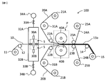
- FIG. 1 is a side view showing a schematic configuration of an apparatus for producing an electrolyte membrane with a catalyst layer, which is an embodiment of the membrane / catalyst junction manufacturing apparatus of the present invention.
- the production of the electrolyte membrane with a catalyst layer is carried out as follows.
- the electrolyte membrane 10 is unwound from the electrolyte membrane supply roll 11 and supplied to the thermocompression bonding portion P through the guide roll 12.
- the catalyst layer transfer sheet supply rolls 21A and 21B are installed above and below the unwound electrolyte membrane 10, respectively.
- the catalyst layer bonded to the upper surface of the electrolyte membrane 10 is formed by using the catalyst layer transfer sheet 20A.
- the catalyst layer transfer sheet 20A is prepared in advance on a sheet serving as a base material by, for example, applying a catalyst solution, and is unwound from the catalyst layer transfer sheet supply roll 21A with the base material supporting the catalyst layer, and the backup roll 31A.
- the catalyst layer transfer sheet 20B for forming the catalyst layer formed on the lower surface of the electrolyte membrane 10 is unwound from the catalyst layer transfer sheet supply roll 21B, and supports the base material side in this order of the backup roll 31B and the guide roll 22B. It is transported while being carried. In this way, the surfaces of the catalyst layer transfer sheets 20A and 20B on which the catalyst layers are formed are supplied to the thermocompression bonding portion P so as to face the electrolyte membrane 10.
- the material of the base material of the catalyst layer transfer sheets 20A and 20B is not particularly limited, and polyethylene terephthalate (PET), polyethylene naphthalate (PEN), polyethylene (PE), polypropylene (PP), polyimide, polyphenylene sulfide, etc.
- Hydrocarbon-based plastic films typified by, perfluoroalkoxy alkane (PFA), polytetrafluoroethylene (PTFE), ethylene tetrafluoroethylene copolymer (ETFE) and the like can be used.
- the base material has breathability. Having air permeability means having a property of allowing gas to permeate, and examples thereof include a case where it has pores communicating with each other in the thickness direction of the base material.
- a breathable base material By using a breathable base material, the liquid vapor generated during thermocompression bonding can be effectively discharged even when the base material is still bonded to the catalyst layer.
- a porous body formed from the above-mentioned material can be used as the base material having breathability.
- the membrane / catalyst junction manufacturing apparatus 100 is configured to transfer the catalyst layer to both sides of the electrolyte membrane 10, but the catalyst layer is transferred to only one side of the electrolyte membrane 10. It may be configured as.
- the spray nozzle 30A is provided between the guide roll 12 and the thermocompression bonding portion P.
- the spray nozzle 30A has a discharge port directed toward the electrolyte membrane surface, and is provided at a position separated from the electrolyte membrane surface by a predetermined distance.
- One or more spray nozzles 30A are provided in the width direction of the electrolyte membrane 10 according to the width of the electrolyte membrane 10.
- the spray nozzle 30A is supplied with water from a water supply tank (not shown), discharges the supplied water from the discharge port, and imparts droplets to the joint surface of the electrolyte membrane with the catalyst layer.
- the spray nozzle 30A and the space S in which the droplets from the discharge port of the spray nozzle 30A to the electrolyte membrane fly are surrounded by the nozzle chamber 32A, and the nozzle chamber 32A has a pressure reducing tank 34A for reducing the pressure in the space S. It is connected by a pipe via a valve 33A that switches the depressurization.
- the pressure reducing tank 34A By making the space S negative with respect to the environmental pressure of the manufacturing apparatus by the pressure reducing tank 34A, the outside air is slightly sucked from the gap provided between the nozzle chamber 32A and the electrolyte membrane 10 from the spray nozzle 30A. Prevents excess droplets from scattering around.
- the water collected in the nozzle chamber 32A is discharged from a drain (not shown) provided in the nozzle chamber 32A, returned to the water supply tank, and reused.
- the nozzle chambers 32A and 32B do not have to be depressurized, but it is preferable to depressurize the nozzle chambers 32A and 32B because it is possible to prevent the droplets from scattering around. In this case, if the degree of decompression is too large, the amount of outside air sucked into the nozzle chambers 32A and 32B becomes large, so that the air flow in the nozzle chambers 32A and 32B is turbulent, and the accuracy of applying droplets may decrease.
- the degree of decompression of the nozzle chambers 32A and 32B is preferably in the range of -50.0 kPa, preferably in the range of -10.0 kPa, with respect to the environmental pressure (atmospheric pressure) of the manufacturing apparatus, for example, -5.
- a range up to 0.0 kPa is more preferred.
- the electrolyte membrane 10 in which the liquid is applied to the bonding surface of the catalyst layer transfer sheets 20A and 20B with the catalyst layer is supplied to the thermocompression bonding portion P and passes between the thermal press rolls 40A and 40B.
- the heat shield plates 41A and 41B it is possible to prevent the liquid applied to the electrolyte membrane 10 from evaporating before the hot press due to the radiant heat radiated from the hot press rolls 40A and 40B.
- the thermal press rolls 40A and 40B are connected to a driving means (not shown) and can rotate while controlling the speed.
- the hot press rolls 40A and 40B rotate at a constant speed while applying heat and pressure to the electrolyte membrane 10 and the catalyst layer transfer sheets 20A and 20B, thereby synchronizing the transport speeds of the electrolyte membrane 10 and the catalyst layer transfer sheets 20A and 20B.
- the catalyst layer is thermally pressure-bonded to both sides of the electrolyte membrane 10 to form the membrane-catalyst layer junction 13a.
- the heating device, the pressurizing device, and the like are not shown.
- the materials of the hot press rolls 40A and 40B are not particularly limited, but one roll is made of a metal such as stainless steel, and the other roll is made of an elastic body such as a resin or an elastomer material typified by rubber as a surface layer. It is preferable to have a coated structure.
- the hot press rolls 40A and 40B as a metal, the electrolyte membrane and the catalyst layer can be sufficiently heated, and by using the surface layer of the other press roll as an elastic body, the press roll can be sufficiently heated. Is flexibly deformed with respect to the catalyst layer transfer sheets 20A and 20B, and by maintaining good line contact, it is possible to make the line pressure in the width direction of the base material uniform.
- the material of the elastic body for example, fluorine rubber, silicon rubber, EPDM (ethylene / propylene / diene rubber), neoprene, CSM (chlorosulfonated polyethylene rubber), urethane rubber, NBR (nitrile rubber) , Ebonite and the like can be used.
- the rubber hardness of the elastic body is preferably in the range of 70 to 97 ° according to the Shore A standard.
- the amount of deformation of the elastic body is appropriate, the sandwiching contact width between the catalyst layer transfer sheets 20A and 20B does not become too large, and it is necessary for joining the electrolyte membrane 10 and the catalyst layer.
- the pinching contact width does not become too small, and the pinching time required for joining can be secured.
- heating means for the heat press rolls 40A and 40B various heaters, steam, oil and other heat media can be used, but the heating means are not particularly limited. Further, the heating temperature may be the same temperature for the upper and lower rolls, or may be different temperatures.
- the method of controlling the pinching pressure in the hot press rolls 40A and 40B is not particularly limited, and the pinching pressure may be controlled by using a pressurizing means such as a hydraulic cylinder, or the hot pressing may be performed by position control using a servomotor or the like.
- a gap may be provided between the rolls 40A and 40B at regular intervals, and the pinching pressure may be controlled by the size of the gap.
- thermocompression bonding portions P use the thermal press rolls 40A and 40B, which are wire contact mechanisms, but the present invention is not limited to this.
- a mechanism for sandwiching the electrolyte membrane 10 and the catalyst layer transfer sheets 20A and 20B by a plurality of line contacts by a plurality of rolls may be used, or a double belt press mechanism for sandwiching the catalyst layer transfer sheets 20A and 20B may be used.
- the number of rolls installed is not particularly limited, but is preferably 2 to 10 sets.
- the catalyst layer is transferred to both sides of the electrolyte membrane 10 through the thermocompression bonding portion P to form a membrane-catalyst junction (electrolyte membrane with a catalyst layer) 13a.
- the temporary base materials 24A and 24B are peeled off from the membrane-catalyst bonded body 13a as the electrolyte membrane with the catalyst layer.
- the peeling method is not particularly limited. For example, it can be passed between the guide rolls 23A and 23B, and at this time, the temporary base materials 24A and 24B can be peeled off. Further, since the temporary base material supports the electrolyte membrane via the catalyst layer while the temporary base material is bonded, the effect of preventing the swelling of the electrolyte membrane can be obtained. Therefore, when it is difficult to evaporate almost the entire amount of the liquid only by the thermocompression bonding step, an additional drying step for drying the liquid is provided between the time when the liquid passes through the thermocompression bonding portion P and the time when the temporary base material is peeled off. You can also do it.
- the above-mentioned additional drying step can also serve as a heating step.
- the drying temperature (hot air temperature or surface temperature of the heating roll) is, for example, 120 ° C. to 250 ° C., preferably 150 ° C. to 230 ° C.
- the temporary base material 24A and 24B are non-breathable base materials
- the temporary base material 24A is held by the hot press roll 40A and the temporary base material 24B is held by the hot press roll 40B as shown in FIG. It is preferable to peel off from the catalyst bonding body 13a. By peeling off the temporary base material immediately after thermocompression bonding to expose the catalyst layer, the liquid vapor generated in the thermocompression bonding process can be effectively discharged.
- the temporary base material peeled off from the membrane / catalyst layer bonded body 13a passes through the guide rolls 23A and 23B, respectively, and is wound up by the temporary base material winding rolls 25A and 25B.
- the membrane-catalyst bonded body 13a from which the temporary base materials 24A and 24B have been peeled off is sent out by the sending roll 14 and wound into a roll by the winding roll 15.
- the delivery roll 14 can be connected to a driving means (not shown), and when the press rolls 40A and 40B do not sandwich the electrolyte membrane 10 and the catalyst layer transfer sheets 20A and 20B, the speed is controlled to control the speed of the electrolyte membrane 10. Can be transported.
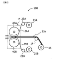
- FIG. 2 is a side view showing a schematic configuration of an apparatus for manufacturing a membrane electrode assembly, which is an embodiment of the membrane / catalyst assembly manufacturing apparatus of the present invention.
- the membrane electrode assembly is manufactured as follows. The description of the same parts as in the first embodiment will be omitted.
- the gas diffusion electrodes 80A and 80B are supplied from the gas diffusion electrode supply rolls 81A and 81B instead of the catalyst layer transfer sheet used in the first embodiment.
- Gas diffusion electrode supply rolls 81A and 81B are installed above and below the unwound electrolyte membrane 10, respectively.
- the gas diffusion electrode 80A bonded to the upper surface of the electrolyte film 10 is unwound from the gas diffusion electrode supply roll 81A, and the backup roll 31A and the guide roll 22A are in this order, respectively, on the opposite side of the gas diffusion electrode from the catalyst layer forming surface. It is conveyed while being supported on the base material side.
- the gas diffusion electrode 80B bonded to the lower surface of the electrolyte film 10 is unwound from the gas diffusion electrode supply roll 81B, and the backup roll 31B and the guide roll 22B are in this order, respectively, and the gas diffusion electrode group on the opposite side to the catalyst layer forming surface. It is conveyed while being supported on the material side. In this way, the surface of the gas diffusion electrodes 80A and 80B on which the catalyst layer is formed is supplied to the thermocompression bonding portion P so as to face the electrolyte membrane 10.
- the electrolyte membrane 10 to which the liquid is applied to the bonding surfaces of the gas diffusion electrodes 80A and 80B and the gas diffusion electrodes 80A and 80B is supplied to the thermocompression bonding portion P, passes between the thermocompression bonding portions 40A and 40B, and is bonded.
- Membrane / catalyst assembly membrane / electrode assembly 13b.
- the membrane-catalyst assembly 13b as the membrane electrode assembly is delivered by the delivery roll 14 and wound into a roll by the take-up roll 15.
- the membrane / catalyst junction manufacturing apparatus 101 is configured to transfer the gas diffusion electrodes 80A and 80B to both sides of the electrolyte membrane 10, but gas diffuses only to one side of the electrolyte membrane 10.
- the electrodes may be configured to transfer.
- the gas diffusion electrode is one in which the above-mentioned catalyst layer is laminated on the electrode base material.
- the electrode base material those operating as gas diffusion electrodes such as a polymer electrolyte fuel cell, a polymer electrolyte membrane type water electrolyzer, and an electrochemical hydrogen pump are used.
- the material include carbonaceous and conductive inorganic substances, and more specifically, a calcined product from polyacrylonitrile, a calcined product from pitch, a carbon material such as graphite and expanded graphite, stainless steel, molybdenum, and the like. Examples include titanium.
- conductive fibers such as carbon fibers are preferable from the viewpoint of fuel permeability.
- a woven fabric plain weave, twill weave, satin weave, crest weave, binding weave and the like are used without particular limitation.
- the non-woven fabric is not particularly limited, such as a papermaking method, a needle punching method, a spunbonding method, a water jet punching method, and a melt blowing method. It may also be a knit.
- a woven fabric obtained by carbonizing or graphiteizing a plain woven fabric using flame-resistant spun yarn, or a non-woven fabric processing of flame-resistant yarn by a needle punch method or a water jet punch method is then carbonized.
- a graphitized non-woven fabric, a flame-resistant yarn, a carbide yarn, or a matte non-woven fabric by a papermaking method using a graphite yarn is preferably used.
- Examples of the carbon fibers used for such an electrode base material include polyacrylonitrile (PAN) -based carbon fibers, phenol-based carbon fibers, pitch-based carbon fibers, rayon-based carbon fibers and the like.
- PAN polyacrylonitrile
- As such an electrode base material for example, carbon paper TGP series and SO series manufactured by Toray Industries, Inc., carbon cloth manufactured by E-TEK, etc. are used.
- the electrode base material has a water-repellent treatment for preventing a decrease in gas diffusion / permeability due to water retention, a partial water-repellent treatment for forming a water discharge path, a hydrophilic treatment, and a reduction in resistance. It is also possible to add carbon powder for this purpose, platinum plating for imparting potential corrosion resistance, and the like. Further, a conductive intermediate layer containing at least an inorganic conductive substance and a hydrophobic polymer can be provided between the electrode base material and the catalyst layer.
- the electrode base material is a carbon fiber woven fabric or a non-woven fabric having a large porosity
- the performance deterioration due to the catalyst solution permeating into the gas diffusion layer can be suppressed by providing the conductive intermediate layer.
- the catalyst layer forming apparatus 102 shown in FIG. 3 first forms the first catalyst layer on one side of the electrolyte membrane. The formation of the first catalyst layer is carried out as follows.
- the electrolyte membrane 10' is supplied to the catalyst layer forming apparatus 102 in a state of being supported on the support.
- the material of the support of the electrolyte membrane is not particularly limited, but for example, a PET film can be used.
- the electrolyte membrane 10'with the support is unwound from the electrolyte membrane supply roll 11 and supplied to the catalyst solution coating means 72 through the guide roll 12.
- the catalyst solution coating means 72 is provided so as to face the electrolyte membrane 10'supported on the backup roll 73.
- the catalyst solution coating means 72 forms a coating film by supplying a catalyst solution from the catalyst solution tank 70 using the catalyst solution feeding pump 71 and applying the supplied catalyst solution onto the electrolyte membrane.
- the method for applying the catalyst solution in the catalyst solution application means 72 is not particularly limited. Methods such as a gravure coater, a die coater, a comma coater, a roll coater, a spray coater, and a screen printing method can be used.
- the catalyst solution is applied to the electrolyte membrane 10'to form the catalyst layer, but the catalyst layer may be transferred and formed on the electrolyte membrane 10'using a catalyst layer transfer sheet. ..
- the coating film of the catalyst solution formed on the electrolyte membrane is dried by the drying means 74, and the solvent in the catalyst solution is evaporated to form the dried first catalyst layer.
- the method for drying the catalyst solution in the drying means 74 is not particularly limited. A method of blowing a heat medium such as hot air or a heat oven method using a heat heater can be used.
- the membrane in which the first catalyst layer is formed on the electrolyte membrane and the first catalyst layer junction 16 are sent out by the delivery roll 14 and wound into a roll by the winding roll 17 with the support attached. Taken.
- the membrane / catalyst conjugate manufacturing apparatus 103 forms a second catalyst layer on the back surface of the surface on which the first catalyst layer of the electrolyte membrane is formed.
- the formation of the second catalyst layer is carried out as follows.
- the membrane / first catalyst layer junction 16 is unwound from the supply roll 18, passes through the guide roll 12, and the support 51 is peeled off from the interface with the electrolyte membrane via the guide rolls 26A and 26B. At this time, the peeled support 51 is wound around the support winding roll 50.
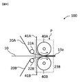
- the cover film 61 unwound from the cover film supply roll 60 is laminated on the first catalyst layer surface via the guide rolls 27A and 27B on the film / first catalyst layer joint 16 from which the support 51 has been peeled off. After that, it is supplied to the thermocompression bonding portion P.
- the cover film 61 may be laminated before the support 51 is peeled off.
- the cover film 61 is used to protect the first catalyst layer during the process of forming the second catalyst layer, and the material is particularly limited as long as it does not interfere with the function of the catalyst layer by attachment / detachment. It is not something that is done.
- sheets of natural fibers typified by paper, etc., and carbonized typified by polyethylene terephthalate (PET), polyethylene naphthalate (PEN), polyethylene (PE), polypropylene (PP), polyimide, polyphenylene sulfide, etc.
- Fluorine-based films such as hydrogen-based plastic films, perfluoroalkoxy alkanes (PFA), polytetrafluoroethylene (PTFE), and ethylene tetrafluoroethylene copolymers (ETFE), or acrylic adhesives and urethanes for these materials. It is possible to use a material to which an acrylate-based pressure-sensitive adhesive, a rubber-based pressure-sensitive adhesive, a silicone-based pressure-sensitive adhesive, or the like is applied to improve the adhesion to the adherend. If the material has improved adhesion, the electrolyte membrane can be supported while the electrolyte membrane is in contact with the liquid, so that the effect of preventing the swelling of the electrolyte membrane can be further obtained.
- PFA perfluoroalkoxy alkanes
- PTFE polytetrafluoroethylene
- ETFE ethylene tetrafluoroethylene copolymers
- the film / first catalyst layer bonded body 16 supplied to the thermocompression bonding portion P is in a state where the first catalyst layer is covered with a cover film by the same liquid application step and thermocompression bonding step as in the first embodiment.
- the second catalyst layer is thermocompression bonded to form a membrane-catalyst bonded body (electrolyte membrane with a catalyst layer) 13c.
- the film-catalyst bonding body 13c as an electrolyte membrane with a catalyst layer that has passed through the thermocompression bonding portion P passes between the guide rolls 23A and 23B, and at this time, the temporary base material 24A is peeled off from the film-catalyst layer bonding body 13c. It is wound by the temporary base material winding roll 25A.
- the membrane-catalyst bonded body 13c from which the temporary base material 24A has been peeled off is sent out by the feeding roll 14 and wound into a roll by the winding roll 15.
- the cover film 61 may be wound in a state of being bonded to the membrane-catalyst bonded body 13c, or may be peeled off from the membrane-catalyst bonded body 13c with a hot press roll 40B immediately after pressing.
- a hot press roll 40B By winding the cover film 61 in a state of being bonded to the membrane-catalyst bonded body 13c, wrinkles and elongation of the electrolyte membrane with the catalyst layer can be suppressed, and the catalyst layer can be protected from physical damage due to external factors.
- the cover film 61 immediately after the thermocompression bonding to expose the catalyst layer the liquid vapor generated in the thermocompression bonding step can be effectively discharged. In this case, the catalyst layer can be protected with a new cover film before winding.
- the first catalyst layer is formed on one side of the electrolyte membrane by the membrane / catalyst junction manufacturing apparatus 104 according to the embodiment shown in FIG.
- the formation of the first catalyst layer is carried out as follows.
- the electrolyte membrane 10' is supplied to the catalyst layer forming apparatus 104 in a state of being supported on the support.
- the electrolyte membrane 10'with a support is unwound from the electrolyte membrane supply roll 11 and supplied to the thermocompression bonding portion P.
- the electrolyte membrane 10'supplied to the thermocompression bonding portion P is thermocompression bonded to the first catalyst layer by the same liquid application step and thermocompression bonding step as in the first embodiment, and the membrane / first catalyst layer bonded body 16 '.
- the membrane / first catalyst layer joint 16' is sent out by the delivery roll 14 with the support and the temporary base material of the catalyst layer transfer sheet 20A attached, and is wound into a roll by the winding roll 17.
- the catalyst layer forming apparatus 105 forms a second catalyst layer on the back surface of the surface on which the first catalyst layer of the electrolyte membrane is formed.
- the formation of the second catalyst layer is carried out as follows.
- the membrane / first catalyst layer junction 16' is unwound from the supply roll 18, and the support 51 is peeled off from the interface with the electrolyte membrane via the guide rolls 26A and 26B. At this time, the peeled support 51 is wound around the support winding roll 50.
- the membrane / first catalyst layer junction 16'with the support 51 peeled off has a second catalyst layer formed by the catalyst solution coating means 72 and the drying means 74 as in the third embodiment, and the membrane / catalyst junction (Electrolyte membrane with catalyst layer) 13d.
- the membrane-catalyst junction 13d as the electrolyte membrane with the catalyst layer is sent out by the sending roll 14, and is wound into a roll by the winding roll 15 with the temporary base material attached.
- the catalyst layer transfer sheet is a catalyst composed of a Pt-supported carbon catalyst TEC10E50E manufactured by Tanaka Kikinzoku Kogyo Co., Ltd. and a "Nafion" (registered trademark) solution on a continuous band-shaped PTFE sheet as a base material.
- a catalyst layer transfer sheet roll (base material width 100 mm, thickness 8 ⁇ m) using a catalyst layer transfer sheet prepared by applying a coating solution and drying was used (platinum carrier amount: 0.3 mg / cm 2 ). ..
- electrolyte membranes in Examples 2 to 6 were produced with reference to the production method described in JP-A-2018-60789.
- Example 1 One of a commercially available "Nafion” (registered trademark) membrane, product name NR211 (thickness 25 ⁇ m), which was used as an electrolyte membrane according to the method described in the first embodiment described above using the apparatus having a schematic configuration shown in FIG. The catalyst layer was transferred from the above-mentioned catalyst layer transfer sheet to the surface of.
- Nafion registered trademark
- liquid application step 100% pure water was applied to the electrolyte membrane in the form of droplets in an amount of 0.5 ⁇ L per 1 cm 2 using a fan-shaped spray nozzle CBIMV 80055S manufactured by Ikeuchi Co., Ltd.
- thermocompression bonding step a pair of thermal press rolls having a diameter of 250 mm were used, and one of the rolls was a stainless steel roll and the other was a fluorine rubber roll having a hardness of 90 ° (shore A).
- the pressure of the hot press roll was 3.0 MPa.
- the pressure is a measured value using a prescale manufactured by FUJIFILM Corporation.
- the roll surface temperature was 160 ° C., and the heating temperature was measured with a thermocouple provided at the bonding interface and found to be 115 ° C.
- the transport speed of the electrolyte membrane and the catalyst layer transfer sheet was 4.0 m / min.
- Example 2 Using the apparatus having a schematic configuration shown in FIG. 1, according to the method described in the first embodiment described above, on one surface of a polyetherketone-based polymer electrolyte membrane made of a polymer represented by the following formula (G1). , The catalyst layer was transferred from the same catalyst layer transfer sheet used in Example 1 described above.
- thermocompression bonding step a pair of thermal press rolls having a diameter of 250 mm were used, and one of the rolls was a stainless steel roll and the other was a fluorine rubber roll having a hardness of 90 ° (shore A).
- the pressure of the hot press roll was 4.5 MPa.
- the pressure is a measured value using a prescale manufactured by FUJIFILM Corporation.
- the temperature of the roll surface was 160 ° C., and the heating temperature was measured by a thermocouple provided at the bonding interface and found to be 115 ° C.
- the transport speed of the electrolyte membrane and the catalyst layer transfer sheet was 4.0 m / min.
- Example 3 Using the apparatus having a schematic configuration shown in FIG. 1, according to the method described in the first embodiment described above, on one surface of a polyarylene-based polymer electrolyte membrane made of a polymer represented by the following formula (G2), The catalyst layer was transferred from the above-mentioned catalyst layer transfer sheet.
- Example 4 Using the apparatus having a schematic configuration shown in FIG. 1, a polyether composed of a segment represented by the following formula (G3) and a segment represented by the following formula (G4) according to the method described in the first embodiment described above.
- the catalyst layer was transferred from the above-mentioned catalyst layer transfer sheet to one surface of the sulfone-based polymer electrolyte membrane.
- thermocompression bonding step (In equations (G3) and (G4), p, q and r are integers, p is 170, q is 380, and r is 4.)
- the liquid application step and the thermocompression bonding step were carried out in the same manner as in Example 2.
- Example 5 An electrolyte membrane with a catalyst layer was produced according to the method described in the third embodiment described above.
- a catalyst solution was applied to one surface of a polyetherketone-based polymer electrolyte membrane made of a polymer represented by the formula (G1), dried, and the first catalyst was used. A layer was formed.
- a catalyst coating solution consisting of a Pt-supported carbon catalyst TEC10E50E manufactured by Tanaka Kikinzoku Kogyo Co., Ltd. and a "Nafion" (registered trademark) solution was used. Drying at 120 ° C. for 5 minutes gave a catalyst layer having a layer thickness of 5 ⁇ m.
- the catalyst layer transfer sheet described above was applied to the other surface of the polyetherketone-based polymer electrolyte membrane on which the first catalyst layer was formed.
- the catalyst layer was transferred from the catalyst layer to form a second catalyst layer.
- a PET film "Lumirror” (registered trademark) film thickness of 75 ⁇ m manufactured by Toray Industries, Inc. was used as the cover film to be laminated on the first catalyst layer surface.
- the same method as in Example 2 was used for the liquid application step and the thermocompression bonding step.
- Example 6 An electrolyte membrane with a catalyst layer was produced according to the method described in the fourth embodiment described above.
- the first catalyst layer from the above-mentioned catalyst layer transfer sheet was placed on one surface of the polyetherketone-based polymer electrolyte membrane made of the polymer represented by the above formula (G1) by using the apparatus having a schematic configuration shown in FIG. Was transcribed.
- the same method as in Example 2 was used for the liquid application step and the thermocompression bonding step.
- Example 6 using the apparatus having the schematic configuration shown in FIG. 6, the same catalyst solution as in Example 5 was applied to the other surface of the electrolyte membrane on which the first catalyst layer was formed, dried, and the second catalyst was formed. A layer was formed.
- Example 7 A membrane-catalyst conjugate was produced in the same manner as in Example 1 except that the following composite electrolyte membrane was used as the electrolyte membrane. As a result of visual evaluation of the obtained membrane-catalyst conjugate, there was no transfer failure of the catalyst layer, no swelling or wrinkles of the electrolyte membrane, and the quality was high.
- ⁇ Composite electrolyte membrane> A composite electrolyte membrane obtained by impregnating a 6 ⁇ m-thick PTFE porous substrate (registered trademark of “Tetra Latex” manufactured by Donaldson) with the following fluorine-based electrolyte solution.
- Example 8 A membrane-catalyst conjugate was produced in the same manner as in Example 5 except that the following composite electrolyte membrane was used as the electrolyte membrane. As a result of visual evaluation of the obtained membrane-catalyst conjugate, there was no transfer failure of the catalyst layer, no swelling or wrinkles of the electrolyte membrane, and the quality was high.
- ⁇ Composite electrolyte membrane> A composite electrolyte membrane obtained by impregnating a 6 ⁇ m-thick PTFE porous substrate (registered trademark of “Tetra Latex” manufactured by Donaldson) with the following hydrocarbon-based electrolyte solution.
- a nonionic fluorine-based surfactant (Neos (Neos (Neos)) is added to 100 parts by mass of an N-methylpyrrolidone (NMP) solution (electrolyte concentration: 13% by mass) in which a polyether ketone polymer electrolyte represented by the formula (G1) is dissolved.
- NMP N-methylpyrrolidone
- G1 polyether ketone polymer electrolyte represented by the formula (G1) is dissolved.
- Example 9 In the manufacturing apparatus of FIG. 1, a membrane-catalyst bonded body was manufactured in the same manner as in Example 1 except that the nozzle chambers 32A and 32B were not depressurized. As a result of visual evaluation of the obtained membrane-catalyst conjugate, there was no transfer failure of the catalyst layer, no swelling or wrinkles of the electrolyte membrane, and the quality was high.
- the catalyst layer was obtained by transferring the catalyst layer from the same catalyst layer transfer sheet as that used in Example 1 above to one surface of the electrolyte membrane in the same manner as in Example 2 except that the liquid application step was not carried out. As a result of visual evaluation of the membrane-catalyst bonded body, transfer failure of the catalyst layer was observed.
- the membrane-catalyst conjugate of the present invention is applied to, for example, an electrolyte membrane with a catalyst layer or a membrane-electrode junction, such as a polymer electrolyte fuel cell, a polymer electrolyte membrane water electrolyzer, and an electrochemical hydrogen pump.
- an electrolyte membrane with a catalyst layer or a membrane-electrode junction such as a polymer electrolyte fuel cell, a polymer electrolyte membrane water electrolyzer, and an electrochemical hydrogen pump.
- the membrane / catalyst assembly of the present invention is an electrolyte membrane with a catalyst layer, it is preferable to further laminate an electrode base material and apply it to the above application as a membrane / electrode assembly.
Landscapes
- Chemical & Material Sciences (AREA)
- Chemical Kinetics & Catalysis (AREA)
- Engineering & Computer Science (AREA)
- Manufacturing & Machinery (AREA)
- General Chemical & Material Sciences (AREA)
- Electrochemistry (AREA)
- Sustainable Energy (AREA)
- Life Sciences & Earth Sciences (AREA)
- Sustainable Development (AREA)
- Crystallography & Structural Chemistry (AREA)
- Physics & Mathematics (AREA)
- Thermal Sciences (AREA)
- Composite Materials (AREA)
- Fuel Cell (AREA)
- Inert Electrodes (AREA)
- Catalysts (AREA)
- Organic Low-Molecular-Weight Compounds And Preparation Thereof (AREA)
Priority Applications (7)
| Application Number | Priority Date | Filing Date | Title |
|---|---|---|---|
| JP2021512598A JP7586072B2 (ja) | 2019-12-23 | 2020-12-21 | 膜・触媒接合体の製造方法、及び製造装置 |
| EP20904552.5A EP4084158A4 (en) | 2019-12-23 | 2020-12-21 | Manufacturing method and manufacturing device for film/catalyst assembly |
| KR1020227014788A KR20220119001A (ko) | 2019-12-23 | 2020-12-21 | 막·촉매 접합체의 제조 방법 및 제조 장치 |
| US17/785,530 US11929511B2 (en) | 2019-12-23 | 2020-12-21 | Manufacturing method and manufacturing device for film/catalyst assembly |
| CN202080086139.6A CN114788058A (zh) | 2019-12-23 | 2020-12-21 | 膜·催化剂接合体的制造方法、及制造装置 |
| CA3163203A CA3163203A1 (en) | 2019-12-23 | 2020-12-21 | Manufacturing method and manufacturing device for film/catalyst assembly |
| AU2020413859A AU2020413859B2 (en) | 2019-12-23 | 2020-12-21 | Manufacturing method and manufacturing device for film/catalyst assembly |
Applications Claiming Priority (2)
| Application Number | Priority Date | Filing Date | Title |
|---|---|---|---|
| JP2019231591 | 2019-12-23 | ||
| JP2019-231591 | 2019-12-23 |
Publications (1)
| Publication Number | Publication Date |
|---|---|
| WO2021132137A1 true WO2021132137A1 (ja) | 2021-07-01 |
Family
ID=76574172
Family Applications (1)
| Application Number | Title | Priority Date | Filing Date |
|---|---|---|---|
| PCT/JP2020/047640 Ceased WO2021132137A1 (ja) | 2019-12-23 | 2020-12-21 | 膜・触媒接合体の製造方法、及び製造装置 |
Country Status (8)
| Country | Link |
|---|---|
| US (1) | US11929511B2 (https=) |
| EP (1) | EP4084158A4 (https=) |
| JP (1) | JP7586072B2 (https=) |
| KR (1) | KR20220119001A (https=) |
| CN (1) | CN114788058A (https=) |
| AU (1) | AU2020413859B2 (https=) |
| CA (1) | CA3163203A1 (https=) |
| WO (1) | WO2021132137A1 (https=) |
Cited By (1)
| Publication number | Priority date | Publication date | Assignee | Title |
|---|---|---|---|---|
| US20230332306A1 (en) * | 2022-04-15 | 2023-10-19 | Twelve Benefit Corporation | COx ELECTROLYZER CELL FLOW FIELDS AND GAS DIFFUSION LAYERS |
Families Citing this family (1)
| Publication number | Priority date | Publication date | Assignee | Title |
|---|---|---|---|---|
| CN119480936B (zh) * | 2024-10-31 | 2025-10-14 | 南京师范大学泰州学院 | 一种全固态电池的正极极片的制备装置 |
Citations (7)
| Publication number | Priority date | Publication date | Assignee | Title |
|---|---|---|---|---|
| JP2004253267A (ja) * | 2003-02-20 | 2004-09-09 | Jsr Corp | 電解膜−電極基板複合体の製造方法 |
| JP2005158518A (ja) * | 2003-11-26 | 2005-06-16 | Jsr Corp | 電解質膜と電極の接合体の製造方法 |
| JP2005222894A (ja) * | 2004-02-09 | 2005-08-18 | Aisin Seiki Co Ltd | 膜電極接合体の製造方法 |
| JP4240272B2 (ja) | 2002-05-14 | 2009-03-18 | トヨタ自動車株式会社 | 膜触媒層接合体の製造方法 |
| JP2009140652A (ja) | 2007-12-04 | 2009-06-25 | Toyota Motor Corp | 膜・電極接合体の製造方法 |
| JP2013069535A (ja) | 2011-09-22 | 2013-04-18 | Nitto Denko Corp | 高分子電解質型燃料電池用膜電極接合体の製造方法 |
| JP2018060789A (ja) | 2016-09-30 | 2018-04-12 | 東レ株式会社 | 高分子電解質組成物ならびにそれを用いた高分子電解質膜、触媒層付き電解質膜、膜電極複合体、固体高分子形燃料電池、電気化学式水素ポンプおよび水電解式水素発生装置 |
Family Cites Families (7)
| Publication number | Priority date | Publication date | Assignee | Title |
|---|---|---|---|---|
| JP2002289207A (ja) * | 2001-03-26 | 2002-10-04 | Matsushita Electric Ind Co Ltd | 燃料電池用触媒層付き水素イオン伝導性高分子膜の製造方法 |
| JP2007053064A (ja) * | 2005-08-19 | 2007-03-01 | Nissan Motor Co Ltd | 膜電極接合体とその製造方法および製造装置 |
| JP2007258022A (ja) * | 2006-03-23 | 2007-10-04 | Nissan Motor Co Ltd | 膜電極接合体の製造装置および製造方法 |
| US20120003572A1 (en) * | 2010-02-10 | 2012-01-05 | Jun Matsumura | Manufacturing method and manufacturing apparatus for catalyst-coated membrane assembly |
| KR101846039B1 (ko) * | 2010-09-13 | 2018-04-05 | 도판 인사츠 가부시키가이샤 | 막 전극 접합체, 막 전극 접합체의 제조 방법 및 연료 전지 |
| WO2012081169A1 (ja) * | 2010-12-16 | 2012-06-21 | パナソニック株式会社 | 膜-触媒層接合体の製造方法 |
| JP2018055945A (ja) * | 2016-09-28 | 2018-04-05 | 三菱自動車工業株式会社 | 燃料電池スタック |
-
2020
- 2020-12-21 KR KR1020227014788A patent/KR20220119001A/ko active Pending
- 2020-12-21 WO PCT/JP2020/047640 patent/WO2021132137A1/ja not_active Ceased
- 2020-12-21 CN CN202080086139.6A patent/CN114788058A/zh active Pending
- 2020-12-21 AU AU2020413859A patent/AU2020413859B2/en active Active
- 2020-12-21 US US17/785,530 patent/US11929511B2/en active Active
- 2020-12-21 EP EP20904552.5A patent/EP4084158A4/en active Pending
- 2020-12-21 CA CA3163203A patent/CA3163203A1/en active Pending
- 2020-12-21 JP JP2021512598A patent/JP7586072B2/ja active Active
Patent Citations (7)
| Publication number | Priority date | Publication date | Assignee | Title |
|---|---|---|---|---|
| JP4240272B2 (ja) | 2002-05-14 | 2009-03-18 | トヨタ自動車株式会社 | 膜触媒層接合体の製造方法 |
| JP2004253267A (ja) * | 2003-02-20 | 2004-09-09 | Jsr Corp | 電解膜−電極基板複合体の製造方法 |
| JP2005158518A (ja) * | 2003-11-26 | 2005-06-16 | Jsr Corp | 電解質膜と電極の接合体の製造方法 |
| JP2005222894A (ja) * | 2004-02-09 | 2005-08-18 | Aisin Seiki Co Ltd | 膜電極接合体の製造方法 |
| JP2009140652A (ja) | 2007-12-04 | 2009-06-25 | Toyota Motor Corp | 膜・電極接合体の製造方法 |
| JP2013069535A (ja) | 2011-09-22 | 2013-04-18 | Nitto Denko Corp | 高分子電解質型燃料電池用膜電極接合体の製造方法 |
| JP2018060789A (ja) | 2016-09-30 | 2018-04-12 | 東レ株式会社 | 高分子電解質組成物ならびにそれを用いた高分子電解質膜、触媒層付き電解質膜、膜電極複合体、固体高分子形燃料電池、電気化学式水素ポンプおよび水電解式水素発生装置 |
Non-Patent Citations (1)
| Title |
|---|
| See also references of EP4084158A4 |
Cited By (2)
| Publication number | Priority date | Publication date | Assignee | Title |
|---|---|---|---|---|
| US20230332306A1 (en) * | 2022-04-15 | 2023-10-19 | Twelve Benefit Corporation | COx ELECTROLYZER CELL FLOW FIELDS AND GAS DIFFUSION LAYERS |
| US12077874B2 (en) * | 2022-04-15 | 2024-09-03 | Twelve Benefit Corporation | COx electrolyzer cell flow fields and gas diffusion layers |
Also Published As
| Publication number | Publication date |
|---|---|
| KR20220119001A (ko) | 2022-08-26 |
| US20230058120A1 (en) | 2023-02-23 |
| CA3163203A1 (en) | 2021-07-01 |
| AU2020413859B2 (en) | 2026-03-12 |
| JP7586072B2 (ja) | 2024-11-19 |
| EP4084158A1 (en) | 2022-11-02 |
| EP4084158A4 (en) | 2024-12-18 |
| AU2020413859A1 (en) | 2022-08-11 |
| JPWO2021132137A1 (https=) | 2021-07-01 |
| CN114788058A (zh) | 2022-07-22 |
| US11929511B2 (en) | 2024-03-12 |
Similar Documents
| Publication | Publication Date | Title |
|---|---|---|
| CN101617424B (zh) | 固体高分子型燃料电池用膜电极接合体的制造方法及固体高分子型燃料电池的制造方法 | |
| JP6529982B2 (ja) | 触媒コーティング型の膜シールアセンブリを製造する方法 | |
| US20130045438A1 (en) | Producing method of fuel cell membrane electrode assembly and producing apparatus of the same | |
| JP5196717B2 (ja) | 触媒層転写シート、触媒層−電解質膜積層体の製造方法、電極−電解質膜接合体の製造方法、および燃料電池の製造方法 | |
| JP7567889B2 (ja) | 膜・触媒接合体の製造方法、及び製造装置 | |
| CN101395750A (zh) | 制备膜电极组件的方法 | |
| WO2021132137A1 (ja) | 膜・触媒接合体の製造方法、及び製造装置 | |
| JP7626064B2 (ja) | 膜・電極接合体の製造方法、及び製造装置 | |
| JP2007048701A (ja) | 転写シート、触媒層−電解質膜積層体、電極−電解質膜接合体及びこれらの製造方法 | |
| JP7110961B2 (ja) | 燃料電池用膜電極ガス拡散層接合体の製造方法 | |
| JP2008166117A (ja) | 燃料電池用膜・電極接合体の製造方法 | |
| TW201825276A (zh) | 用於將層轉印之轉印片及附有電極觸媒層之片材 |
Legal Events
| Date | Code | Title | Description |
|---|---|---|---|
| ENP | Entry into the national phase |
Ref document number: 2021512598 Country of ref document: JP Kind code of ref document: A |
|
| 121 | Ep: the epo has been informed by wipo that ep was designated in this application |
Ref document number: 20904552 Country of ref document: EP Kind code of ref document: A1 |
|
| ENP | Entry into the national phase |
Ref document number: 3163203 Country of ref document: CA |
|
| NENP | Non-entry into the national phase |
Ref country code: DE |
|
| ENP | Entry into the national phase |
Ref document number: 2020904552 Country of ref document: EP Effective date: 20220725 |
|
| ENP | Entry into the national phase |
Ref document number: 2020413859 Country of ref document: AU Date of ref document: 20201221 Kind code of ref document: A |