WO2021132089A1 - ヘッドアップディスプレイ装置 - Google Patents
ヘッドアップディスプレイ装置 Download PDFInfo
- Publication number
- WO2021132089A1 WO2021132089A1 PCT/JP2020/047469 JP2020047469W WO2021132089A1 WO 2021132089 A1 WO2021132089 A1 WO 2021132089A1 JP 2020047469 W JP2020047469 W JP 2020047469W WO 2021132089 A1 WO2021132089 A1 WO 2021132089A1
- Authority
- WO
- WIPO (PCT)
- Prior art keywords
- display
- light
- display light
- viewer
- angle
- Prior art date
- Legal status (The legal status is an assumption and is not a legal conclusion. Google has not performed a legal analysis and makes no representation as to the accuracy of the status listed.)
- Ceased
Links
Images


Classifications
-
- B—PERFORMING OPERATIONS; TRANSPORTING
- B60—VEHICLES IN GENERAL
- B60K—ARRANGEMENT OR MOUNTING OF PROPULSION UNITS OR OF TRANSMISSIONS IN VEHICLES; ARRANGEMENT OR MOUNTING OF PLURAL DIVERSE PRIME-MOVERS IN VEHICLES; AUXILIARY DRIVES FOR VEHICLES; INSTRUMENTATION OR DASHBOARDS FOR VEHICLES; ARRANGEMENTS IN CONNECTION WITH COOLING, AIR INTAKE, GAS EXHAUST OR FUEL SUPPLY OF PROPULSION UNITS IN VEHICLES
- B60K35/00—Instruments specially adapted for vehicles; Arrangement of instruments in or on vehicles
- B60K35/20—Output arrangements, i.e. from vehicle to user, associated with vehicle functions or specially adapted therefor
- B60K35/21—Output arrangements, i.e. from vehicle to user, associated with vehicle functions or specially adapted therefor using visual output, e.g. blinking lights or matrix displays
- B60K35/23—Head-up displays [HUD]
- B60K35/233—Head-up displays [HUD] controlling the size or position in display areas of virtual images depending on the condition of the vehicle or the driver
-
- B—PERFORMING OPERATIONS; TRANSPORTING
- B60—VEHICLES IN GENERAL
- B60K—ARRANGEMENT OR MOUNTING OF PROPULSION UNITS OR OF TRANSMISSIONS IN VEHICLES; ARRANGEMENT OR MOUNTING OF PLURAL DIVERSE PRIME-MOVERS IN VEHICLES; AUXILIARY DRIVES FOR VEHICLES; INSTRUMENTATION OR DASHBOARDS FOR VEHICLES; ARRANGEMENTS IN CONNECTION WITH COOLING, AIR INTAKE, GAS EXHAUST OR FUEL SUPPLY OF PROPULSION UNITS IN VEHICLES
- B60K35/00—Instruments specially adapted for vehicles; Arrangement of instruments in or on vehicles
- B60K35/20—Output arrangements, i.e. from vehicle to user, associated with vehicle functions or specially adapted therefor
- B60K35/21—Output arrangements, i.e. from vehicle to user, associated with vehicle functions or specially adapted therefor using visual output, e.g. blinking lights or matrix displays
- B60K35/22—Display screens
-
- B—PERFORMING OPERATIONS; TRANSPORTING
- B60—VEHICLES IN GENERAL
- B60K—ARRANGEMENT OR MOUNTING OF PROPULSION UNITS OR OF TRANSMISSIONS IN VEHICLES; ARRANGEMENT OR MOUNTING OF PLURAL DIVERSE PRIME-MOVERS IN VEHICLES; AUXILIARY DRIVES FOR VEHICLES; INSTRUMENTATION OR DASHBOARDS FOR VEHICLES; ARRANGEMENTS IN CONNECTION WITH COOLING, AIR INTAKE, GAS EXHAUST OR FUEL SUPPLY OF PROPULSION UNITS IN VEHICLES
- B60K35/00—Instruments specially adapted for vehicles; Arrangement of instruments in or on vehicles
- B60K35/80—Arrangements for controlling instruments
-
- B—PERFORMING OPERATIONS; TRANSPORTING
- B60—VEHICLES IN GENERAL
- B60R—VEHICLES, VEHICLE FITTINGS, OR VEHICLE PARTS, NOT OTHERWISE PROVIDED FOR
- B60R11/00—Arrangements for holding or mounting articles, not otherwise provided for
- B60R11/02—Arrangements for holding or mounting articles, not otherwise provided for for radio sets, television sets, telephones, or the like; Arrangement of controls thereof
-
- G—PHYSICS
- G02—OPTICS
- G02B—OPTICAL ELEMENTS, SYSTEMS OR APPARATUS
- G02B27/00—Optical systems or apparatus not provided for by any of the groups G02B1/00 - G02B26/00, G02B30/00
- G02B27/01—Head-up displays
Definitions
- This disclosure relates to a head-up display device.
- the head-up display device described in Patent Document 1 has a light emitting diode, a liquid crystal display panel that receives light from the light emitting diode and emits display light, and a virtual image by reflecting the display light toward the windshield. It includes a concave mirror to be visually recognized, and a stepping motor and gears for rotating the concave mirror in order to adjust the irradiation position of the display light on the front glass.
- the inventors of the present application change the angle of incidence of the display light on the windshield when the irradiation position of the display light on the windshield changes due to the rotation of the concave mirror, thereby visually recognizing. It was discovered that the position where the display light is applied to the person shifts. In this way, if the position where the display light is irradiated to the viewer shifts, it becomes difficult to irradiate the viewer with high-brightness display light, and the display quality of the virtual image deteriorates. Was discovered by.
- the present disclosure has been made in view of the above circumstances, and an object of the present disclosure is to provide a head-up display device capable of suppressing deterioration of display quality.
- the head-up display device is A head-up display device that allows a viewer to visually recognize a virtual image by irradiating a projected member with display light representing information.
- An indicator that receives the light from the light source and emits the display light
- a reflector that guides the display light from the display to the projected member
- a drive unit that adjusts the angle of the reflector in order to move the irradiation position of the display light to the viewer in the vertical direction.
- a control unit that controls the plurality of light sources is provided.
- the control unit An eyebox-corresponding range corresponding to the viewer's eyebox is set in a part of the display light-irradiable area in which the display light can be irradiated to the viewer by turning on the plurality of light sources.
- the viewpoint information was acquired, the viewpoint region located within the eye box correspondence range was determined in correspondence with the viewpoint of the viewer located in the eye box included in the viewpoint information, and the viewpoint region was determined among the plurality of light sources.
- One or more of the light sources corresponding to the viewpoint region are turned on, and the light sources are turned on. Based on the angle of the reflecting mirror adjusted by the driving unit, the position of the eyebox corresponding range in the display light irradiation area is set.
- deterioration of display quality can be suppressed.
- FIG. 1 It is a figure which shows the position of the eye box correspondence range occupying the display light irradiation possible area when the vehicle which concerns on one Embodiment of this disclosure is a right-hand drive vehicle. It is a figure which shows the windshield and the head-up display device. It is a cross-sectional view of the F15-F15 line of FIG. It is a cross-sectional view of the F16-F16 line of FIG. It is a figure which shows the windshield and the head-up display device. It is a vertical cross-sectional view of the F18-F18 line of FIG. It is a vertical cross-sectional view of the F19-F19 line of FIG.
- the direction T indicates the upward direction
- the direction B indicates the downward direction
- the direction R indicates the right direction
- the direction L indicates the left direction
- the direction F indicates the front of the vehicle
- the direction Rr indicates the rear of the vehicle. Is shown.
- the left-right direction indicates the direction seen from the driver, and is a direction along the vehicle width direction indicated by the direction Vw.
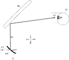
- the head-up display HUD is mounted on the instrument panel of the vehicle and emits the display light DL to the windshield WS of the vehicle.
- the head-up display HUD emits a display light DL to a windshield WS, for example, a portion of the windshield facing the driver's seat.
- the display light DL represents vehicle information such as the traveling speed of the vehicle, various vehicle warnings, and route guidance information.
- vehicle information such as the traveling speed of the vehicle, various vehicle warnings, and route guidance information.
- the head-up display HUD includes a display 1, a reflector 2, a control unit 3, and a reflector drive unit 4.
- the display 1 is controlled by the control unit 3 to display an image representing vehicle information, and emits a display light DL representing this image.
- the reflector 2 folds back the display light DL inside the housing of the head-up display HUD and reflects it toward the windshield WS.
- the reflector 2 is, for example, a concave mirror.
- the reflector drive unit 4 is controlled by the control unit 3 and rotates the reflector 2 around the rotation axis AX.
- the rotation axis AX is along the vehicle width direction, and in FIG. 1, it is along the paper vertical direction.
- the irradiation position of the display light DL with respect to the viewer Vr can be moved in the vertical direction (T direction and B direction).
- the display 1 includes a plurality of light sources 11, a lens group 12, and a liquid crystal panel 13.
- the lens group 12 includes a first field lens 12a and a second field lens 12b.
- the lens group 12 is a front-stage optical member (backlight optical member) designed so that the illumination light emitted from any of the reference light sources 11A among the plurality of light sources 11 transmits and illuminates the entire surface of the liquid crystal panel 13. Further, in the lens group 12, the display light DL emitted from the liquid crystal panel 13 is visually recognized at an arbitrary position in the eye box EB via the rear-stage optical member (HUD optical member composed of the reflecting mirror 2 and the windshield WS). It is designed to reach the eyes of the person Vr.
- HUD optical member composed of the reflecting mirror 2 and the windshield WS
- the plurality of light sources 11 are composed of 35 LED (Light Emitting Diode) light sources of 5 vertical x 7 horizontal lights arranged on a two-dimensional plane.
- This two-dimensional plane is a mounting surface of a substrate on which a plurality of light sources 11 are mounted.
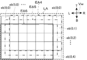
- Each of the light sources 11 (0,0) to 11 (6,4) corresponds to the constituent regions eb (0,0) to eb (6,4) constituting the display light irradiation capable region LA.
- the display light irradiation area LA is the maximum range in which the display light DL can irradiate the viewer Vr.
- the display light DL is irradiated over the entire area of the display light irradiation enable area LA.
- the display light irradiation area LA is divided into a grid pattern of vertical 5 ⁇ horizontal 7.
- the vertical direction is along the vertical direction (T direction and B direction)
- the horizontal direction is along the vehicle width direction (Vw direction).
- control unit 3 controls the display 1 and the reflector drive unit 4.
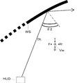
- control unit 3 adjusts the angle ⁇ of the reflector 2 according to the sitting height of the viewer Vr through the reflector drive unit 4 based on the operation of an operation switch (not shown) by the viewer Vr.
- the control unit 3 adjusts the angle ⁇ of the reflector 2 according to the sitting heights H1, H2, and H3 of the viewer Vr.
- the angle ⁇ of the reflecting mirror 2 is an angle in the tangential direction of the center point of the reflecting surface of the reflecting mirror 2 with respect to the vehicle front-rear direction (direction F and direction Rr). As the angle ⁇ of the reflector 2 increases, the irradiation position of the display light DL moves upward.
- the reflector 2 when the viewer Vr is the sitting height H1, the reflector 2 is set to the first angle ⁇ 1 so that the irradiation position of the display light DL suitable for the viewer Vr at the sitting height H1 is obtained.
- the reflector 2 when the viewer Vr has a sitting height H2 higher than the sitting height H1, the reflector 2 is set to a second angle ⁇ 2 which is an angle larger than the first angle ⁇ 1 so that the sitting height H2 can be visually recognized.
- the irradiation position of the display light DL suitable for the person Vr As shown in FIG.
- the reflector 2 is set to a third angle ⁇ 3 which is an angle larger than the second angle ⁇ 2, so that the sitting height H3 can be visually recognized.
- the irradiation position of the display light DL suitable for the person Vr.
- the control unit 3 changes the position of the eyebox compatible range EA occupying the display light irradiation range LA according to the angle ⁇ of the reflector 2, and then changes the position of the eyebox compatible range EA.
- the eye box correspondence range EA is set as a part of the display light irradiation enable area LA, and is a region corresponding to the eye box EB of the viewer Vr.
- the eyebox correspondence range EA is composed of, for example, a constituent area of 4 vertical ⁇ 6 horizontal.
- the control unit 3 acquires the viewpoints VrR and VrL in the eyebox EB based on the viewpoint information IE from the viewpoint detection device 9.
- control unit 3 determines the viewpoint region VA in the eye box correspondence range EA corresponding to the viewpoint VrR and VrL in the acquired eye box EB. Further, the control unit 3 lights a single or a plurality of light sources 11 corresponding to the determined viewpoint region VA among the plurality of light sources 11. The processing content of the control unit 3 will be described in detail later.
- the control unit 3 determines which of the first angle ⁇ 1, the second angle ⁇ 2, and the third angle ⁇ 3 is closer to the angle ⁇ of the reflector 2.
- the first angle ⁇ 1 is an angle smaller than the second angle ⁇ 2, and the second angle ⁇ 2 is an angle smaller than the third angle ⁇ 3.
- the eyebox correspondence range EA1 is set on the outside and the upper side of the vehicle away from the passenger seat when viewed from the driver's seat in the vehicle width direction.
- the eyebox correspondence range EA1 is composed of the upper left vertical 4 ⁇ horizontal 6 constituent areas of all the constituent areas eb (0,0) to eb (6,4).
- the eyebox correspondence range EA3 is set on the inside and the bottom of the vehicle approaching the passenger seat when viewed from the driver's seat in the vehicle width direction.
- the eyebox correspondence range EA3 is composed of a vertical 4 ⁇ horizontal 6 constituent area in the lower right of all the constituent areas eb (0,0) to eb (6,4).
- the control unit 3 determines that the angle ⁇ of the reflector 2 is the closest to the second angle ⁇ 2, as shown in FIG. 12, the eye box is located in the center of the display light irradiation area LA.
- the eyebox correspondence range EA2 is composed of a central vertical 4 ⁇ horizontal 6 constituent area of all the constituent areas eb (0,0) to eb (6,4).
- the control unit 3 moves upward as the angle ⁇ of the reflector 2 increases, in other words, as the irradiation position of the display light DL on the windshield WS moves upward. Slide the position of the eyebox compatible range EA in the display light irradiation area LA to the lower right.
- the control unit 3 determines that the angle ⁇ of the reflector 2 is the closest to the first angle ⁇ 1, as shown by the alternate long and short dash line in FIG. 13, the upper right (right) of the display light irradiation range LA.
- the eyebox correspondence range EA4 is set on the outside and the upper side of the vehicle away from the passenger seat when viewed from the driver's seat in the vehicle width direction.
- the eyebox correspondence range EA4 is composed of a vertical 4 ⁇ horizontal 6 constituent area in the upper right of all the constituent areas eb (0,0) to eb (6,4).
- the eyebox correspondence range EA6 is set on the inside and below of the vehicle approaching the passenger seat when viewed from the driver's seat in the vehicle width direction.
- the eyebox correspondence range EA6 is composed of a vertical 4 ⁇ horizontal 6 constituent area in the lower left of all the constituent areas eb (0,0) to eb (6,4).
- the eyebox correspondence range EA5 is composed of a central vertical 4 ⁇ horizontal 6 constituent area of all the constituent areas eb (0,0) to eb (6,4).
- the control unit 3 moves upward as the angle ⁇ of the reflector 2 increases, in other words, as the irradiation position of the display light DL on the windshield WS moves upward.
- the eyebox correspondence range EA occupying the display light irradiation area LA is set to be flipped horizontally.
- control unit 3 adjusts the angle ⁇ of the reflector 2 through the reflector drive unit 4 based on the switch operation by the viewer Vr (step S101). As a result, the irradiation position of the display light DL is adjusted according to the sitting height of the viewer Vr.
- control unit 3 sets the position of the eyebox corresponding range EA in the display light irradiation area LA based on the angle ⁇ of the reflector 2 (step S102).
- control unit 3 determines the viewpoints VrR and VrL of the viewer Vr in the eyebox EB based on the viewpoint information IE from the viewpoint detection device 9 (step S103).
- the control unit 3 associates the eyebox EB with the eyebox correspondence range EA to determine the viewpoint region VA which is a part of the eyebox correspondence range EA corresponding to the viewpoints VrR and VrL in the eyebox EB.
- the light source 11 corresponding to the determined viewpoint region VA is turned on (step S104), and the light source lighting process is completed.
- two viewpoint areas VA are determined in the eyebox correspondence range EA corresponding to the two viewpoints VrR and VrL.
- the positions of the two viewpoints VrR and VrL in the eyebox EB correspond to the positions of the two viewpoint areas VA in the eyebox correspondence range EA.
- each of the two viewpoint areas VA is a viewpoint. Determined to include VrR, VrL.
- the viewpoint VrR is located at the center of the eyebox EB.
- the control unit 3 is a left-hand steering wheel and the reflector 2 has a first angle ⁇ 1
- the viewpoint region VA1 including (4,2), eb (3,1), and eb (3,2) is determined.
- the control unit 3 displays the light sources 11 (4, 1), 11 (4, 2), 11 (3, 1), and 11 (3, 2) corresponding to the determined viewpoint region VA1 in FIGS. 2 and 3. It lights up as the reference light source 11A shown.
- control unit 3 is a left-hand steering wheel and the reflector 2 has a second angle ⁇ 2
- the control unit 3 is a viewpoint composed of a constituent area eb (3, 2) located at the center of the eye box correspondence range EA2 shown in FIG.
- the region VA2 is determined, and the light sources 11 (3, 2) corresponding to the determined viewpoint region VA2 are turned on as the reference light source 11A shown in FIGS. 2 and 3.
- the control unit 3 is a left-hand steering wheel and the reflector 2 has a third angle ⁇ 3
- the control units 3 have constituent regions eb (3, 1) and eb (3, 1) located at the center of the eye box correspondence range EA3 shown in FIG.
- the viewpoint region VA3 including 3,2), eb (2,1), and eb (2,2) is determined. Then, the control unit 3 shows the light sources 11 (3,1), 11 (3,2), (2,1), 11 (2,2) corresponding to the determined viewpoint region VA3 in FIGS. 2 and 3. It lights up as a reference light source 11A.
- the viewpoint VrR is located at the center of the eyebox EB, but the present invention is not limited to this, and when the viewpoint VrR is located outside the center of the eyebox EB, the viewpoint areas VA1, VA2, and VA3 are located at the center of the eyebox EB. Correspondence range It is located outside the center of EA1, EA2, and EA3.
- the viewpoint region VA is determined in the same manner as the viewpoint VrR.
- the control unit 3 has different viewpoint regions VA1, VA2, VA3 for each of the determined eyebox correspondence ranges EA1, EA2, and EA3 even if the light sources VrR and VrL exist at the same position in the eyebox EB. Is determined, and the light source 11 corresponding to the determined viewpoint regions VA1, VA2, and VA3 is turned on as the reference light source 11A. In this way, by turning on the reference light source 11A among the plurality of light sources 11, the brightness of the display light DL at the viewpoints VrR and VrL in the eyebox EB can be increased. Further, since the light sources other than the reference light source 11A among the plurality of light sources 11 are turned off, heat generation of the light source 11 can be suppressed and power saving can be achieved.
- the control unit 3 may turn on the light source corresponding to the periphery of the constituent area as well as the constituent area in which the viewpoints VrR and VrL exist.
- the brightness (lighting intensity) of the reference light source 11A corresponding to the constituent region in which the viewpoints VrR and VrL exist is a
- the brightness of the left and right light sources of the reference light source 11A is b
- the control unit 3 lights only the reference light source 11A or the reference light source 11A and the nearby light source corresponding to the constituent area where the viewpoint detected through the viewpoint information IE is located.
- a decrease in display quality such as a decrease in the brightness of the virtual image Vi seen from the viewer Vr due to a fine movement of the viewpoint of the viewer Vr.
- eight surrounding light sources are turned on as the vicinity of the reference light source 11A, but the present invention is not limited to this, and four light sources such as up, down, left, and right may be used. The smaller the number of lighting light sources, the more power is saved, and the heat generated by the light sources can be suppressed.
- the reference light source 11A is not limited to a single light source, and may be a plurality of reference light sources.
- the windshield WS is formed of a transparent plate material having a free curved surface curved so as to be recessed when viewed from the viewer Vr along the vertical direction and the vehicle width direction. Since the windshield WS has a free curved surface, the incident angle of the display light DL changes due to the change in the irradiation position of the display light DL on the windshield WS, and the position of the display light DL reaching the viewer Vr changes. In addition, the cross-sectional shape of the display light DL when reaching the viewer Vr may be distorted.
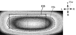
- the position of the high-luminance range Hb with respect to the eyebox EB shifts in the vertical direction (T direction and B direction) and the vehicle width direction (Vw direction).
- the brightness of the virtual image Vi seen from the viewer Vr may decrease due to the minute movement of the viewpoint of the viewer Vr, and the display quality may deteriorate.
- the windshield WS is formed in a shape in which the radius of curvature along the vehicle width direction (Vw direction) increases toward the lower side. Therefore, when the display light DL shown in FIG. 15 is irradiated to the lower side of the windshield WS, the incident angle ⁇ 1 seen from above is such that the display light DL shown in FIG. 16 is irradiated to the upper side of the windshield WS. It is larger than the incident angle ⁇ 2 seen from above in the case.
- the brightness of the virtual image Vi seen from the viewer Vr may decrease due to the minute movement of the viewpoint of the viewer Vr in the vehicle width direction, and the display quality may deteriorate.
- the display light DL is incident on the windshield WS at an incident angle ⁇ 2, as shown in FIG. 21, the position of the high luminance range Hb with respect to the eyebox EB in the vehicle width direction as compared with the case of FIG. Is not out of alignment.
- the display light DL is irradiated to the lower side of the windshield WS, that is, the angle of the reflector 2.
- ⁇ is small
- the position of the eyebox-corresponding range EA in the display light irradiation area LA is shifted to the outside of the vehicle away from the passenger seat when viewed from the viewer Vr in the driver's seat.
- the positional deviation of the high-luminance range Hb with respect to the eyebox EB in the vehicle width direction is eliminated as compared with the comparative example.
- the windshield WS is formed in a shape in which the radius of curvature along the vertical direction (T direction and B direction) becomes smaller toward the lower side.
- the difference in the radius of curvature along the vertical direction between the upper side and the lower side of the windshield WS is smaller than the difference in the radius of curvature along the vehicle width direction between the upper side and the lower side of the windshield WS described above. ..
- the incident angle ⁇ 1 seen from the vehicle width direction when the display light DL shown in FIG. 19 is irradiated to the lower side of the windshield WS is when the display light DL shown in FIG.
- the display light DL is incident on the windshield WS at the incident angle ⁇ 1
- the reflected light of the display light DL is directed downward as compared with the case where the display light DL is incident on the windshield WS at the incident angle ⁇ 2. Therefore, in the comparative example, when the display light DL is incident on the windshield WS at the incident angle ⁇ 1, the position of the high-luminance range Hb with respect to the eyebox EB may be shifted downward as shown in FIG. is there.
- the brightness of the virtual image Vi seen from the viewer Vr may decrease due to the minute movement of the viewpoint of the viewer Vr in the vertical direction, and the display quality may deteriorate.
- the display light DL is incident on the windshield WS at an incident angle ⁇ 2, as shown in FIG. 21, the position of the high luminance range Hb with respect to the eyebox EB in the vertical direction is higher than that in the case of FIG. It is not out of alignment.
- the display light DL is irradiated to the lower side of the windshield WS, that is, the angle ⁇ of the reflector 2.
- the position of the eyebox correspondence range EA in the display light irradiation area LA is shifted upward.
- the vertical positional deviation of the high-luminance range Hb with respect to the eye box EB is eliminated as compared with the comparative example.
- the head-up display device HUD causes the viewer Vr to visually recognize the virtual image Vi by irradiating the windshield WS, which is an example of the projected member, with the display light DL representing the vehicle information.
- the head-up display device HUD has a plurality of light sources 11 arranged on a two-dimensional plane, a display 1 that receives illumination light from the light source 11 and emits display light DL, and a display light DL from the display 1.
- a control unit 3 for the operation is provided.
- the control unit 3 corresponds to the eye box EB of the viewer Vr in a part of the display light irradiable region LA that can irradiate the display light DL to the viewer Vr by turning on all of the plurality of light sources 11.
- Set the eyebox compatible range EA Set the eyebox compatible range EA.
- control unit 3 acquires the viewpoint information Ie and determines the viewpoint area VA located in the eyebox correspondence range EA in correspondence with the viewpoint of the viewer Vr located in the eyebox EB included in the viewpoint information Ie. Then, one or a plurality of light sources 11 corresponding to the determined viewpoint region VA among the plurality of light sources 11 are turned on. Further, the control unit 3 sets the position of the eyebox correspondence range EA in the display light irradiation range LA based on the angle ⁇ of the reflector 2 adjusted by the reflector drive unit 4. According to this configuration, the misalignment of the high-luminance range Hb with respect to the eyebox EB is eliminated. Therefore, it is suppressed that the brightness of the virtual image Vi seen from the viewer Vr is lowered due to the minute movement of the viewpoint of the viewer Vr. As a result, deterioration of display quality is suppressed.
- the control unit 3 adjusts the angle ⁇ of the reflector 2 via the reflector drive unit 4, so that the irradiation position of the display light DL on the windshield WS is the lower side of the vehicle windshield where the windshield WS is the irradiation position.
- the position of the eyebox correspondence range EA in the display light irradiation area LA is set to the upper side. According to this configuration, the vertical positional deviation of the high-luminance range Hb with respect to the eyebox EB is eliminated. Therefore, it is possible to prevent the brightness of the virtual image Vi seen from the viewer Vr from being lowered due to the minute movement of the viewpoint in the vertical direction of the viewer Vr. As a result, deterioration of display quality is suppressed.
- the head-up display device HUD irradiates the display light DL on the portion of the windshield of the vehicle, which is the windshield WS, facing the driver's seat.
- the control unit 3 moves the irradiation position of the display light DL to the windshield WS to the lower side of the vehicle windshield which is the windshield WS.
- the position of the eyebox correspondence range EA in the display light irradiation area LA is set to the outside of the vehicle away from the passenger seat with respect to the driver's seat on which the viewer Vr sits.
- the displacement of the high-luminance range Hb with respect to the eyebox EB in the vehicle width direction is eliminated. Therefore, it is possible to prevent the brightness of the virtual image Vi seen from the viewer Vr from being lowered due to the minute movement of the viewpoint in the vehicle width direction of the viewer Vr. As a result, deterioration of display quality is suppressed.
- control unit 3 adjusts the angle ⁇ of the reflector 2 through the reflector drive unit 4 based on the operation of an operation switch (not shown) by the viewer Vr, but the present invention is not limited to this, and the viewpoint detection is not limited to this.
- the sitting height of the viewer Vr may be estimated based on other information such as the viewpoint information Ie from the device 9, and the angle ⁇ of the reflector 2 may be adjusted based on the estimated sitting height of the viewer Vr.
- the number of light sources 11 in the above embodiment can be changed as appropriate.
- the size, aspect ratio, and number of constituent areas of the display light irradiation area LA change according to the number of light sources 11.
- the control unit 3 may gradually slide the eyebox correspondence range EA according to the angle ⁇ of the reflector 2. Further, the size and aspect ratio of the eye box correspondence range EA and the viewpoint area VA can be changed as appropriate.
- the plurality of light sources 11 are arranged in a matrix, the arrangement mode of the light sources 11 is not limited to this. For example, a plurality of light sources are arranged along a first row arranged along the X direction and a second row adjacent to the first row in the Y direction and arranged along the X direction. The light sources in the second row may be provided at different positions in the X direction.
- the X and Y directions extend in directions orthogonal to each other along the two-dimensional plane in which the light source is arranged.
- one light source 11 is associated with one constituent area, but the present invention is not limited to this, and a plurality of light sources 11 may be associated with one constituent area.
- control unit 3 has set various lighting intensities for each of the light sources 11, but the present invention is not limited to this, and a constant lighting intensity may be set.
- the viewpoint information IE is not limited to the viewpoints VrR and VrL of both eyes of the viewer Vr.
- the control unit 3 may obtain the position between the eyebrows of the viewer Vr from the external viewpoint detection device 9 and estimate the viewpoints VrR and VrL of both eyes of the viewer Vr from the position between the eyebrows.
- the viewpoint detection device 9 may be built in the head-up display HUD.
- the number of reflectors 2 is one, but a reflector different from the reflector 2 may be provided between the reflector 2 and the display 1.
- the other reflector may be either a plane mirror or a concave mirror.
- control unit 3 has the same movement amount of the eyebox correspondence range EA due to the change of the angle ⁇ of the reflector 2 in the vertical direction and the vehicle width direction, but they may be different from each other.
Landscapes
- Engineering & Computer Science (AREA)
- Mechanical Engineering (AREA)
- Chemical & Material Sciences (AREA)
- Combustion & Propulsion (AREA)
- Transportation (AREA)
- Physics & Mathematics (AREA)
- General Physics & Mathematics (AREA)
- Optics & Photonics (AREA)
- Instrument Panels (AREA)
- Fittings On The Vehicle Exterior For Carrying Loads, And Devices For Holding Or Mounting Articles (AREA)
Priority Applications (1)
| Application Number | Priority Date | Filing Date | Title |
|---|---|---|---|
| JP2021567401A JP7586096B2 (ja) | 2019-12-25 | 2020-12-18 | ヘッドアップディスプレイ装置 |
Applications Claiming Priority (2)
| Application Number | Priority Date | Filing Date | Title |
|---|---|---|---|
| JP2019233992 | 2019-12-25 | ||
| JP2019-233992 | 2019-12-25 |
Publications (1)
| Publication Number | Publication Date |
|---|---|
| WO2021132089A1 true WO2021132089A1 (ja) | 2021-07-01 |
Family
ID=76574626
Family Applications (1)
| Application Number | Title | Priority Date | Filing Date |
|---|---|---|---|
| PCT/JP2020/047469 Ceased WO2021132089A1 (ja) | 2019-12-25 | 2020-12-18 | ヘッドアップディスプレイ装置 |
Country Status (2)
| Country | Link |
|---|---|
| JP (1) | JP7586096B2 (https=) |
| WO (1) | WO2021132089A1 (https=) |
Cited By (3)
| Publication number | Priority date | Publication date | Assignee | Title |
|---|---|---|---|---|
| US20220219533A1 (en) * | 2021-01-12 | 2022-07-14 | Yazaki Corporation | Vehicle display device |
| WO2023085230A1 (ja) * | 2021-11-12 | 2023-05-19 | 株式会社小糸製作所 | 画像生成装置及びヘッドアップディスプレイ |
| WO2023171550A1 (ja) * | 2022-03-07 | 2023-09-14 | 矢崎総業株式会社 | 車両用表示装置 |
Citations (6)
| Publication number | Priority date | Publication date | Assignee | Title |
|---|---|---|---|---|
| JP2007087792A (ja) * | 2005-09-22 | 2007-04-05 | Minebea Co Ltd | 照明装置及びそれを用いた光源ユニット |
| JP2018072686A (ja) * | 2016-11-01 | 2018-05-10 | 矢崎総業株式会社 | 車両用表示装置 |
| WO2018193708A1 (ja) * | 2017-04-19 | 2018-10-25 | マクセル株式会社 | ヘッドアップディスプレイ装置およびその表示制御方法 |
| JP2019015936A (ja) * | 2017-07-11 | 2019-01-31 | マクセル株式会社 | ヘッドアップディスプレイ装置 |
| WO2019123975A1 (ja) * | 2017-12-21 | 2019-06-27 | 日本精機株式会社 | 表示制御ユニット及びヘッドアップディスプレイ装置 |
| WO2019159572A1 (ja) * | 2018-02-14 | 2019-08-22 | 矢崎総業株式会社 | 投影表示装置 |
Family Cites Families (3)
| Publication number | Priority date | Publication date | Assignee | Title |
|---|---|---|---|---|
| JP6551730B2 (ja) | 2015-04-28 | 2019-07-31 | 株式会社リコー | 画像表示装置及び移動体 |
| JP2018045143A (ja) * | 2016-09-15 | 2018-03-22 | 株式会社デンソー | ヘッドアップディスプレイ装置 |
| JP2020109453A (ja) | 2019-01-07 | 2020-07-16 | 矢崎総業株式会社 | ヘッドアップディスプレイ装置 |
-
2020
- 2020-12-18 WO PCT/JP2020/047469 patent/WO2021132089A1/ja not_active Ceased
- 2020-12-18 JP JP2021567401A patent/JP7586096B2/ja active Active
Patent Citations (6)
| Publication number | Priority date | Publication date | Assignee | Title |
|---|---|---|---|---|
| JP2007087792A (ja) * | 2005-09-22 | 2007-04-05 | Minebea Co Ltd | 照明装置及びそれを用いた光源ユニット |
| JP2018072686A (ja) * | 2016-11-01 | 2018-05-10 | 矢崎総業株式会社 | 車両用表示装置 |
| WO2018193708A1 (ja) * | 2017-04-19 | 2018-10-25 | マクセル株式会社 | ヘッドアップディスプレイ装置およびその表示制御方法 |
| JP2019015936A (ja) * | 2017-07-11 | 2019-01-31 | マクセル株式会社 | ヘッドアップディスプレイ装置 |
| WO2019123975A1 (ja) * | 2017-12-21 | 2019-06-27 | 日本精機株式会社 | 表示制御ユニット及びヘッドアップディスプレイ装置 |
| WO2019159572A1 (ja) * | 2018-02-14 | 2019-08-22 | 矢崎総業株式会社 | 投影表示装置 |
Cited By (7)
| Publication number | Priority date | Publication date | Assignee | Title |
|---|---|---|---|---|
| US20220219533A1 (en) * | 2021-01-12 | 2022-07-14 | Yazaki Corporation | Vehicle display device |
| US12474774B2 (en) | 2021-01-12 | 2025-11-18 | Yazaki Corporation | Vehicle display device |
| WO2023085230A1 (ja) * | 2021-11-12 | 2023-05-19 | 株式会社小糸製作所 | 画像生成装置及びヘッドアップディスプレイ |
| US20250013040A1 (en) * | 2021-11-12 | 2025-01-09 | Koito Manufacturing Co., Ltd. | Image generation apparatus and head-up display |
| WO2023171550A1 (ja) * | 2022-03-07 | 2023-09-14 | 矢崎総業株式会社 | 車両用表示装置 |
| JP2023130073A (ja) * | 2022-03-07 | 2023-09-20 | 矢崎総業株式会社 | 車両用表示装置 |
| JP7538165B2 (ja) | 2022-03-07 | 2024-08-21 | 矢崎総業株式会社 | 車両用表示装置 |
Also Published As
| Publication number | Publication date |
|---|---|
| JPWO2021132089A1 (https=) | 2021-07-01 |
| JP7586096B2 (ja) | 2024-11-19 |
Similar Documents
| Publication | Publication Date | Title |
|---|---|---|
| CN112904558B (zh) | 平视显示器校准 | |
| JP6499632B2 (ja) | 車両用灯具 | |
| JP6140700B2 (ja) | 車両用灯具およびその制御方法 | |
| JP6214389B2 (ja) | 車両用灯具 | |
| JP6524541B2 (ja) | 表示装置 | |
| EP3048362B1 (en) | Vehicle lighting fixture | |
| JP7586096B2 (ja) | ヘッドアップディスプレイ装置 | |
| JP5907384B2 (ja) | 車両用前照灯 | |
| JP6921619B2 (ja) | 車両用灯具および路面描画システム | |
| JP7298069B2 (ja) | 車両用前照灯 | |
| JP2014053184A (ja) | 車両用灯具 | |
| JP2011249183A (ja) | 車両用前照灯システム、制御装置および車両用前照灯装置 | |
| WO2020067497A1 (ja) | 車両用前照灯 | |
| WO2016093154A1 (ja) | 車両用照明装置 | |
| JP2013180713A (ja) | 車載表示装置 | |
| US20230358382A1 (en) | Lamp for vehicle | |
| CN117006434A (zh) | 车灯 | |
| JP2020131922A (ja) | 車両用灯具 | |
| JP2016224077A (ja) | ヘッドアップディスプレイ装置 | |
| JP6978988B2 (ja) | 表示装置、表示制御方法、およびプログラム | |
| JP2020144326A (ja) | 光走査装置、表示システムおよび移動体 | |
| JP2020067461A (ja) | 表示装置 | |
| JP6581442B2 (ja) | 車両用灯具 | |
| JP2018040842A (ja) | ヘッドアップディスプレイ装置 | |
| WO2022019048A1 (ja) | 画像生成装置及びヘッドアップディスプレイ |
Legal Events
| Date | Code | Title | Description |
|---|---|---|---|
| 121 | Ep: the epo has been informed by wipo that ep was designated in this application |
Ref document number: 20907634 Country of ref document: EP Kind code of ref document: A1 |
|
| ENP | Entry into the national phase |
Ref document number: 2021567401 Country of ref document: JP Kind code of ref document: A |
|
| NENP | Non-entry into the national phase |
Ref country code: DE |
|
| 122 | Ep: pct application non-entry in european phase |
Ref document number: 20907634 Country of ref document: EP Kind code of ref document: A1 |